VL2000 Spot Luminaire User Guide - Vari-Lite
VL2000 Spot Luminaire User Guide - Vari-Lite
VL2000 Spot Luminaire User Guide - Vari-Lite

Create successful ePaper yourself
Turn your PDF publications into a flip-book with our unique Google optimized e-Paper software.
VARI❋LITE ® is a trademark owned by Genlyte Thomas Group LLC and is registered in the United States and other countries.<br />
VL1000, <strong>VL2000</strong>, VL2201, VL2202, VL2400 (and the individual product designations), VL3000, Series 1000 , Series 2000 ,<br />
Series 3000 , DICHRO❋TUNE , VARI❋IMAGE , and the <strong>Vari</strong>-<strong>Lite</strong> Asterisk are also trademarks owned by Genlyte Thomas Group LLC.<br />
VARI❋LITE® products are protected by one or more of the following patents, and other pending patent applications worldwide:<br />
U. S. Patents No. 6,123,436; 6,113,252; 6,046,861; 6,031,749; 6,011,640; 5,969,868; 5,959,768; 5,934,794; 5,882,107; 5,829,868; 5,825,548; 5,798,619;<br />
5,774,273; 5,769,527; 5,758,956; 5,728,994; 5,640,061; 5,590,954; 5,454,477; 5,432,691; 5,367,444; 5,329,431; 5,307,295; 5,282,121; 5,278,742; 5,209,560;<br />
5,186,536; 5,073,847; 5,010,459; 4,980,806; 4,972,306; 4,800,474; 4,779,176; 4,701,833; 4,602,321;<br />
U. S. Design Patents No. 439,356; 420,332; 417,300; 415,301; 413,995; 377,338; 366,712; 359,574; 350,408; 347,113;<br />
Australia Patents No. 693,691; 683,695; 667,109; 649,264; 646,588; 586,095; 576,400; 546,433;<br />
Australia Design Patents No. 128,796; 128,795;<br />
Canada Patents No. 2,070,670; 2,050,375; 1,270,675; 1,259,058; 1,181,795;<br />
Canada Design Patents No. 81,234; 81,233; 76,046;<br />
European (UK) Patents No. 0 652 400; 0 586 049; 0 565 218; 0 547 732; 0 534 710; 0 495 305; 0 474 202; 0 379 970; 0 253 082; 0 253 081; 0 248 974; 0 192<br />
882; 0 140 994; 0 060 068;<br />
Germany Patents No. 694 25 943.8; 693 14 122.0; 692 08 615.3; 692 07 692.1; 691 31 478.0; 691 21 029.2; 690 33 385.4; 37 89 166.9; 37 68 727.1; 37 51<br />
804.6; 37 50 201.8; 35 87 270.5; 32 79 888.1; 32 74 291.6;<br />
Germany Design Patents No. M 98 01 745.4; M 96 04 515.9; M 96 04 514.0; M 94 07 689.8; M 94 02 951.2; M 499 03 583.6; M 498 11 203.9; G 93 12 884.3;<br />
Spain Patents No. 2 090 191; 2 084 289; 2 020 960; 0 548 328;<br />
Spain Utility Model Patent No. 2.031.748;<br />
Spain Design Patents No. 0.137.502; 0.137.501; 0.133.573;<br />
Greece Patent No. 910.400.544;<br />
Hong Kong Patents No. 965/1990; 285/1987;<br />
Japan Patents No. 2,843,696; 2,059,669; 2,055,324; 2,002,168; 1,966,525; 1,889,481; 1,792,721; 1,770,241; 1,723,825; 1,683,007; 1,533,011;<br />
Japan Design Patents No. 985,985-1; 985,985; 947,552; 945,436-1; 945,436; 1,106,089; 1,077,598; 1,072,598; 1,060,414; 1,002,123;<br />
Korea Patents No. 76,310; 42,639; 283,770; 181,180;<br />
Korea Design Patents No. 209,896; 209,895;<br />
Mexico Patent No. 180,148;<br />
Singapore Patents No. 663/90; 134/87;<br />
Taiwan Patents No. 78,726; 66,975; 65,380; 28,275;<br />
United Kingdom Design Registrations No. 2082526; 2072562; 2056387; 2056386; 2042174; 2038212; 2033108; 2029499.<br />
All other brand or product names which may be mentioned in this manual are trademarks or registered trademarks of their respective companies or<br />
organizations.<br />
<strong>VL2000</strong> <strong>Spot</strong> <strong>Luminaire</strong> <strong>User</strong>’s Manual<br />
The information furnished in this manual is for informational use only and is subject to change without notice. Please check www.vari-lite.com for latest<br />
version. <strong>Vari</strong>-<strong>Lite</strong> assumes no responsibility or liability for any errors or inaccuracies that may appear in this manual. All information and graphics are<br />
property of Genlyte Thomas Group LLC, 10911 Petal St. Dallas, TX 75238.<br />
Version as of: 02-May-03<br />
Part number: 02.9673.0001 D<br />
<strong>VL2000</strong> <strong>Spot</strong> <strong>Luminaire</strong> <strong>User</strong>’s Manual<br />
©2000-2003 Genlyte Thomas Group LLC. All Rights Reserved.
FOREWORD<br />
How To Obtain Warranty Service<br />
A copy of the <strong>Vari</strong>-<strong>Lite</strong> Limited Warranty was included in the shipping package for this<br />
VARI❋LITE® product.<br />
To obtain warranty service, please contact customer service at 1-877-VARI-LITE (1-877-827-4548) or<br />
customerservice@vari-lite.com and request a Return Material Authorization (RMA) for warranty<br />
service. You will need to provide the model and serial number of the item being returned, a<br />
description of the problem or failure and the name of the registered user or organization. If available,<br />
you should have your sales invoice to establish the date of sale as the beginning of the warranty period.<br />
Once you obtain the RMA, pack the unit in a secure shipping container or in its original packing box.<br />
Fill out the RMA form included at the end of this manual and place in shipping container along with a<br />
copy of your invoice (if available). Write the RMA number legibly on or near the shipping address<br />
label and return the unit, freight prepaid to:<br />
<strong>Vari</strong>-<strong>Lite</strong><br />
10911 Petal St.<br />
Dallas, TX 75238<br />
Attention: Warranty Service<br />
As stated in the warranty, it is required that the shipment be insured and FOB our service center.<br />
02.9673.0001 D 02-May-03 i
VARI❋LITE® - <strong>VL2000</strong> SPOT LUMINAIRE USER’S MANUAL<br />
Compliance Notice<br />
FCC<br />
This equipment has been tested and found to comply with the limits for a Class A digital device<br />
pursuant to Part 15 of FCC Rules. These limits are designed to provide reasonable protection against<br />
harmful interference when this equipment is operated in a commercial environment. This equipment<br />
generates, uses, and can radiate radio frequency energy and, if not installed and used in accordance<br />
with <strong>Vari</strong>-<strong>Lite</strong> system, service, and safety guidelines, may cause harmful interference to radio<br />
communications. Operation of this equipment in a residential area is likely to cause harmful<br />
interference, in which case the user will be required to correct the interference at his/her own expense.<br />
Declaration of Conformity<br />
We declare, under our sole responsibility, that this product complies with the relevant clauses of the<br />
following standards and harmonized documents:<br />
Safety<br />
EN 60598-1:1997 <strong>Luminaire</strong> Safety Standard, General Requirements<br />
EN 60598-2 17:1989 Specification for <strong>Luminaire</strong>s for Stage and Studio Lighting<br />
EMC<br />
EN 55022A:1994 Radiated and Conducted Emissions<br />
EN 50082-1:1997 Generic Immunity Standard<br />
We certify that the product conforms to the protection requirements of council directives: 73/23/EEC<br />
(LVD) and 89/336/EEC (EMC)<br />
ii 02-May-03 02.9673.0001 D
FOREWORD<br />
Safety Notice<br />
It is extremely important to read ALL safety information and instructions provided in this manual and<br />
any accompanying documentation before installing and operating the products described herein. Heed<br />
all cautions and warnings during installation and use of this product.<br />
Safety symbols used throughout this manual are as follows:<br />
CAUTION advising of potential damage to product.<br />
WARNING advising of potential injury or death to persons.<br />
GENERAL INFORMATION PERTAINING TO PROTECTION AGAINST ELECTRICAL SHOCK,<br />
FIRE, EXPOSURE TO EXCESSIVE UV RADIATION, AND INJURY TO PERSONS CAN BE<br />
FOUND BELOW.<br />
WARNING:<br />
INSTRUCTIONS FOR CONTINUED PROTECTION AGAINST FIRE<br />
1. VARI❋LITE® luminaires have been designed for use with specific lamp types. The <strong>VL2000</strong> spot<br />
luminaire requires a certain Philips or Osram HID lamp. Installing another type of lamp may be<br />
hazardous.<br />
2. <strong>Luminaire</strong>s may be mounted on any type of surface as long as mounting instructions are followed.<br />
See instructions detailed in this manual.<br />
3. Note distance requirement from combustible materials or illuminated objects for VARI❋LITE®<br />
luminaires.<br />
WARNING:<br />
INSTRUCTIONS FOR CONTINUED PROTECTION AGAINST ELECTRICAL SHOCK<br />
1. VARI❋LITE® luminaires are designed for dry locations only. Exposure to rain or moisture may<br />
damage luminaire.<br />
2. Disconnect power before servicing any VARI❋LITE® equipment.<br />
3. Servicing to be performed by qualified personnel only.<br />
02.9673.0001 D 02-May-03 iii
VARI❋LITE® - <strong>VL2000</strong> SPOT LUMINAIRE USER’S MANUAL<br />
WARNING:<br />
INSTRUCTIONS FOR CONTINUED PROTECTION AGAINST EXCESSIVE EXPOSURE<br />
TO UV RADIATION<br />
1. Many VARI❋LITE® luminaires use a lamp that produces UV radiation. DO NOT look directly at<br />
lamp.<br />
2. It is hazardous to operate luminaires without lens or shield. Shields, lenses, or ultraviolet screens<br />
shall be changed if they have become visibly damaged to such an extent that their effectiveness is<br />
impaired. For example, by cracks or deep scratches.<br />
WARNING:<br />
INSTRUCTIONS FOR PROTECTION AGAINST INJURY TO PERSONS<br />
1. Exterior surfaces of the luminaire will be hot during operation. Use appropriate safety equipment<br />
(gloves, eye protection, etc.) when handling and adjusting hot equipment and components.<br />
2. <strong>Luminaire</strong>s will have a hot lamp when operating. Disconnect power and allow lamp to cool before<br />
replacing.<br />
3. Arc lamps emit ultraviolet radiation which can cause serious skin burn and eye inflammation.<br />
Additionally, arc lamps operate under high pressure at very high temperatures. Should the lamp<br />
break, there can exist a danger of personal injury and/or fire from broken lamp particles being<br />
discharged.<br />
4. Wear eye protection when relamping.<br />
5. Appropriate safety equipment (gloves, eye protection) should be used when handling damaged<br />
lamps.<br />
6. If lamp is touched with bare hands, clean lamp with denatured alcohol and wipe with lint-free<br />
cloth before installing or powering up the luminaire.<br />
7. The lamp shall be changed if it has become damaged or thermally deformed.<br />
WARNING:<br />
RF INTERFERENCE<br />
1. This is a Class A product. In a domestic environment this product may cause radio interference, in<br />
which case, the user may be required to take adequate measures.<br />
ARC LAMP CHARACTERISTIC CONSIDERATIONS<br />
1. Arc lamps require a period of time to relight after a power interruption or a severe voltage dip. In<br />
some cases, lamp will automatically relight after it has cooled depending on Lamp Power-Up State<br />
configuration setting.<br />
2. Burning position is Universal.<br />
iv 02-May-03 02.9673.0001 D
FOREWORD<br />
Sicherheitshinweise<br />
Es ist äußerst wichtig, ALLE Sicherheitsinformationen und -hinweise in diesem Handbuch und dem<br />
beiliegenden Informationsmaterial zu lesen, bevor Sie die hierin beschriebenen Produkte installieren<br />
bzw. bedienen. Halten Sie bei der Installation und dem Einsatz dieses Produkts alle Warnhinweise und<br />
Vorsichtsmaßnahmen ein.<br />
Folgende Sicherheitssymbole werden in diesem Handbuch verwendet:<br />
VORSICHT - weist auf möglichen Produktschaden hin.<br />
WARNUNG - weist auf mögliche Körperverletzung und Lebensbedrohung hin.<br />
NACHSTEHEND FINDEN SIE ALLGEMEINE HINWEISE ÜBER<br />
SICHERHEITSVORKEHRUNGEN GEGEN ELEKTROSCHOCK, FEUER, ÜBERHÖHTE UV-<br />
STRAHLUNG UND KÖRPERVERLETZUNGEN.<br />
WARNUNG:<br />
HINWEISE ZUM FEUERSCHUTZ<br />
1. VARI❋LITE®-Scheinwerfer sind ausschließlich für den Einsatz mit bestimmten Lampentyps.<br />
Achten Sie auf den Lampentyp (Philips or Osram HID lamp), bevor Sie die jeweiligen Lampen<br />
ersetzen. Die Installation eines anderen Lampentyps kann gefährlich sein.<br />
2. Scheinwerfer können auf jeder beliebigen Oberfläche montiert werden, solange Sie die<br />
Montageanweisungen befolgen. Detaillierte Hinweise finden Sie in diesem Handbuch.<br />
3. Beachten Sie die Einhaltung des erforderlichen Sicherheitsabstandes der VARI❋LITE®-<br />
Scheinwerfer von brennbarem Material oder beleuchteten Objekten.<br />
WARNUNG:<br />
HINWEISE ZUM SCHUTZ GEGEN ELEKTROSCHOCK<br />
1. VARI❋LITE®-Scheinwerfer eignen sich ausschließlich für trockene Standorte. Regen oder<br />
Feuchtigkeit können die Scheinwerfer beschädigen.<br />
2. Unterbrechen Sie die Stromzufuhr, bevor Sie mit der Arbeit an VARI❋LITE®-Geräten beginnen.<br />
3. Die Geräte sollten nur von qualifiziertem Personal gewartet werden.<br />
02.9673.0001 D 02-May-03 v
VARI❋LITE® - <strong>VL2000</strong> SPOT LUMINAIRE USER’S MANUAL<br />
WARNUNG:<br />
HINWEISE ZUM SCHUTZ GEGEN ÜBERHÖHTE UV-STRAHLUNG<br />
1. Viele VARI❋LITE®-Scheinwerfer verwenden die Lampentyp, der UV-Strahlen abgibt.<br />
SCHAUEN SIE NICHT direkt in die Lampe.<br />
2. Es ist gefährlich, Leuchten ohne Linsen oder Blenden zu bedienen. Blenden, Linsen oder<br />
Ultraviolettschirme müssen ausgetauscht werden, sofern deren Schutzwirkung durch sichtbare<br />
Beschädigung (z. B. Sprünge oder Schrammen) eingeschränkt ist.<br />
WARNUNG:<br />
HINWEISE ZUM SCHUTZ GEGEN KÖRPERVERLETZUNGEN<br />
1. Bei Betrieb sind die Außenflächen der Scheinwerfer heiß. Verwenden Sie bei der Bedienung von<br />
aufgeheizter Apparatur die jeweils geeignete Sicherheitsausrüstung (Handschuhe, Augenschutz<br />
etc.).<br />
2. Bei Betrieb der Scheinwerfer ist die Lampe heiß. Unterbrechen Sie die Stromzufuhr und lassen Sie<br />
die Lampe abkühlen, wenn Sie diese austauschen.<br />
3. Bogenlampen senden ultraviolette Strahlen aus, die Hautverbrennungen und Augenentzündungen<br />
verursachen können. Der Betrieb von Bogenlampen erfolgt unter Hochdruck und bei hohen<br />
Temperaturen. Sollte die Lampe zerbrechen, besteht die Gefahr von Körperverletzung bzw. von<br />
Feuer, das von Lampenteilen ausgelöst werden kann.<br />
4. Tragen Sie beim Austausch der Lampen einen Augenschutz.<br />
5. Die geeignete Sicherheitsausrüstung (Handschuhe, Augenschutz) sollte beim Umgang mit<br />
beschädigten Lampen verwendet werden.<br />
6. Wenn die Lampe mit bloßen Händen berührt wird, reinigen Sie sie mit denaturiertem Alkohol und<br />
einem flusenfreien Tuch, bevor Sie die Scheinwerfer installieren oder in Betrieb nehmen.<br />
7. Wenn die Lampe beschädigt oder durch Hitzeeinwirkung deformiert ist, muß diese ausgetauscht<br />
werden.<br />
WARNUNG:<br />
HF-INTERFERENZ<br />
1. Es handelt sich um ein Produkt der Klasse A. In einer Wohnumgebung kann das Produkt Hochfrequenzstörungen<br />
verursachen. In diesem Fall müssen eventuell geeignete Maßnahmen getroffen<br />
werden.<br />
BESONDERHEITEN VON BOGENLAMPEN<br />
1. Bogenlampen benötigen eine gewisse Zeitdauer, um nach einem Stromausfall oder einem<br />
Spannungsgefälle wieder aufzuleuchten. In einigen Fällen wird die Lampe nach Abkühlung<br />
automatisch wieder aufleuchten, je nach der Systemkonfigurationseinstellung des Lampeneinschaltungsstatus.<br />
2. Die Brennposition ist Universal.<br />
vi 02-May-03 02.9673.0001 D
FOREWORD<br />
Notes de sécurité<br />
Avant de procéder à l’installation des produits décrits dans ce guide et de les mettre en marche, il est<br />
extrêmement important de lire TOUS les renseignements et TOUTES les directives de sécurité<br />
contenues dans ce guide ainsi que toute documentation jointe. Tenir compte de tous les avertissements<br />
et suivre toutes les précautions pendant l’installation et l’utilisation de cet appareil.<br />
Les symboles de sécurité utilisés dans ce guide sont les suivants :<br />
ATTENTION Ce symbole annonce que l’appareil risque d’être endommagé.<br />
AVERTISSEMENT Ce symbole annonce qu’il y a risque d’accident grave ou même fatal.<br />
CETTE SECTION CONTIENT DES INFORMATIONS GÉNÉRALES POUR SE PROTÉGER<br />
CONTRE LES DÉCHARGES ÉLECTRIQUES , LES INCENDIES, L’EXPOSITION EXCESSIVE<br />
AUX RAYONS UV ET TOUT AUTRE ACCIDENT POUVANT ENTRAÎNER DES BLESSURES.<br />
AVERTISSEMENT:<br />
DIRECTIVES POUR SE PROTÉGER CONTRE LES INCENDIES<br />
1. Les luminaires VARI❋LITE® ont été conçus pour être utilisés uniquement avec certaines type de<br />
lampes. Vérifier le type de lampe (Philips or Osram HID lamp) avant de remplacer les lampes.<br />
L’installation d’un autre type de lampe peut poser un danger.<br />
2. Les luminaires peuvent être fixés sur tout type de surface tant que les directives de montage sont<br />
respectées. Voir les explications détaillées dans ce guide.<br />
3. Vérifier la distance à respecter entre les matériaux combustibles ou les objets illuminés et les<br />
luminaires VARI❋LITE®.<br />
AVERTISSEMENT:<br />
DIRECTIVES POUR SE PROTÉGER CONTRE LES DÉCHARGES ÉLECTRIQUES<br />
1. Les luminaires VARI❋LITE® sont conçus pour une utilisation au sec uniquement. Une<br />
exposition à la pluie et à l’humidité risque d’endommager le luminaire.<br />
2. Débrancher l’appareil avant de procéder à la révision de tout matériel VARI❋LITE®.<br />
3. Les révisions doivent être effectuées uniquement par des personnes qualifiées.<br />
02.9673.0001 D 02-May-03 vii
VARI❋LITE® - <strong>VL2000</strong> SPOT LUMINAIRE USER’S MANUAL<br />
AVERTISSEMENT:<br />
DIRECTIVES POUR SE PROTÉGER CONTRE UNE EXPOSITION EXCESSIVE AUX<br />
RAYONS UV<br />
1. Plusieurs luminaires VARI❋LITE® utilisent une lampe qui produit des rayons UV. NE PAS fixer<br />
son regard sur la lampe.<br />
2. L’utilisation des luminaires sans lentille ou blindage pose des risques. Tous blindages, lentilles ou<br />
écrans ultraviolet visiblement endommagés au point que leur efficacité en est affectée doivent être<br />
remplacés, par exemple s’il y a des fissures ou de profondes rayures.<br />
AVERTISSEMENT:<br />
DIRECTIVES POUR SE PROTÉGER CONTRE LES ACCIDENTS POUVANT ENTRAÎNER<br />
DES BLESSURES<br />
1. Les surfaces externes du luminaire deviennent brûlantes quand l’appareil est en marche. Pour<br />
manœuvrer ou ajuster des appareils brûlants et leurs composants, se protéger suffisamment (gants,<br />
protection pour les yeux, etc.).<br />
2. La lampe du luminaire est brûlante lorqu’il est en marche. Débrancher le courant et attendre que la<br />
lampe ait refroidi avant de la remplacer.<br />
3. Les lampes à arc émettent des rayons ultraviolets pouvant causer de graves brûlures sur la peau et<br />
une inflammation des yeux. De plus, les lampes à arc fonctionnent sous haute tension à de très<br />
hautes températures. Si la lampe se casse, les particules de la lampe cassée peuvent causer<br />
blessures et/ou incendie en s’éparpillant.<br />
4. Se protéger les yeux pour remplacer la lampe.<br />
5. Utiliser des appareils de protection appropriés (gants, protection des yeux) pour manier des lampes<br />
endommagées.<br />
6. Si la lampe a été touchée avec des mains nues, la nettoyer avec de l’alcool dénaturé et l’essuyer<br />
avec un chiffon non-pelucheux avant d’installer ou de brancher le luminaire.<br />
7. Si la lampe a été endommagée ou a reçu une déformation thermique, elle doit être remplacée.<br />
AVERTISSEMENT:<br />
INTERFÉRENCE RF<br />
1. Cet appareil est de Classe A. Dans un environnement domestique, cet appareil peut causer des<br />
interférences radio, et si c’est le cas, l’utilisateur peut avoir à prendre des mesures adéquates.<br />
CONSIDÉRATIONS DES CARACTÉRISTIQUES DE LAMPES À ARC<br />
1. Après une interruption de courant ou une baisse importante de voltage, les lampes à arc mettent du<br />
temps avant de se rallumer. Dans certains cas, la lampe se rallumera automatiquemet après s’être<br />
refroidie. Cela dépend de la manière dont le système est réglé pour le statut de mise en marche de<br />
la lampe.<br />
2. La position Brûler est Universelle.<br />
viii 02-May-03 02.9673.0001 D
FOREWORD<br />
Aviso sobre Seguridad<br />
Es muy importante leer TODA la información e instrucciones sobre seguridad que se indica en este<br />
manual así como en los documentos adjuntos antes de instalar y operar los productos descritos. Se<br />
debe prestar atención a todos los avisos y advertencias durante la instalación y uso de este producto.<br />
Los símbolos de seguridad usados en este manual son los siguientes:<br />
CUIDADO, indica posibles daños al producto.<br />
ADVERTENCIA, indica posibles lesiones o muerte a las personas.<br />
LA INFORMACIÓN GENERAL RELACIONADA A LA PROTECCIÓN CONTRAGOLPES DE<br />
CORRIENTE ELÉCTRICA, INCENDIO, EXPOSICIÓN EXCESIVA A RADIACIÓN ULTRA<br />
VIOLETA Y LESIONES A LAS PERSONAS SE PUEDE ENCONTRAR SEGUIDAMENTE:<br />
ADVERTENCIA:<br />
INSTRUCCIONES PARA PROTECCIÓN CONTINUA CONTRA INCENDIO<br />
1. Las luminarias VARI❋LITE® han sido diseñadas para ser usadas solamente con algunas<br />
lámparas. Tome nota del tipo de lámpara (Philips or Osram HID lamp) antes de reemplazarla.<br />
Instalación de otro tipo de lámpara puede ser peligroso.<br />
2. Las luminarias se pueden instalar en cualquier tipo de superficie siempre que se sigan las<br />
instrucciones de instalación. Vea las instrucciones detalladas en este manual.<br />
3. Tome nota de los requerimientos de distancia de materiales combustibles u objetos iluminados<br />
para las luminarias VARI❋LITE®.<br />
ADVERTENCIA:<br />
INSTRUCCIONES PARA PROTECCIÓN CONTINUA CONTRA CHOQUE ELÉCTRICO<br />
1. Las luminarias VARI❋LITE® están diseñadas solamente para lugares secos. La exposición a la<br />
lluvia o humedad pueden dañar la luminaria.<br />
2. Desconecte la energía antes de dar servicio a cualquier equipo de VARI❋LITE®.<br />
3. El servicio debe ser realizado solamente por personal calificado.<br />
02.9673.0001 D 02-May-03 ix
VARI❋LITE® - <strong>VL2000</strong> SPOT LUMINAIRE USER’S MANUAL<br />
ADVERTENCIA:<br />
INSTRUCCIONES PARA PROTECCIÓN CONTINUA CONTRA LA EXPOSICIÓN<br />
EXCESIVA DE RADIACIÓN ULTRA VIOLETA<br />
1. Muchas luminarias VARI❋LITE® usan un tipo de lámpara que produce radiación UV. NO mire<br />
directamente a la lámpara.<br />
2. Es peligroso operar luminarias sin lentes o protectores. Debe cambiar los protectores, lentes o<br />
pantallas ultravioletas si se aprecia que han sido dañadas, y que su efectividad pudiera estar<br />
deteriorada. Por ejemplo, si tuvieran rajaduras o raspaduras profundas.<br />
ADVERTENCIA:<br />
INSTRUCCIONES PARA PROTECCIÓN CONTRA LESIONES DE PERSONAS<br />
1. Las superficies exteriores de las luminarias están calientes durante su operación. Use un equipo de<br />
seguridad apropiado (guantes, protección para los ojos, etc.) cuando haga ajustes en el equipo y<br />
componentes que están calientes.<br />
2. Cuando las luminarias están en operación la lámpara estará muy caliente. Desconecte la energía y<br />
deje que la lámpara se enfríe antes de reemplazarla.<br />
3. Las lámparas de arco emiten radiaciones ultravioletas que pueden ocasionar serias quemaduras a la<br />
piel e inflamación a los ojos. Además, las lámparas de arco operan a alta presión y muy alta<br />
temperatura. Si la lámpara se rompe, puede existir el peligro de lesiones al personal o un incendio<br />
ocasionado por las partículas de la lámpara rota que se caen.<br />
4. Use protección para los ojos cuando vuelve a colocar una lámpara nueva.<br />
5. Use un equipo de seguridad apropiado (guantes, protección para los ojos, etc.) cuando trabaje con<br />
lámparas dañadas.<br />
6. Si toca la lámpara con las manos, limpie la lámpara con alcohol desnaturalizado y con tela sin<br />
pelusas antes de instalar o volver a conectar la luminaria.<br />
7. Cambie la lámpara si está dañada o deformada termicamente.<br />
ADVERTENCIA:<br />
INTERFERENCIA RF<br />
1. Este es un producto de Clase A. En el ambiente de la casa este producto puede ocasionar<br />
radiointerferencia, en cuyo caso, el usuario debe tomar las medidas adecuadas.<br />
CONSIDERACIONES SOBRE LAS CARACTERÍSTICAS DE LA LÁMPARA DE ARCO<br />
1. Las lámparas de arco requieren un período de tiempo para volver a iluminarse después de una<br />
interrupción de energía o de una severa caída de voltaje. En algunos casos, la lámpara se volverá a<br />
iluminar en forma automática después que se ha enfriado dependiendo de la configuración del<br />
sistema de energía de la lámpara.<br />
2. La posición de encendido es universal.<br />
x 02-May-03 02.9673.0001 D
FOREWORD<br />
02.9673.0001 D 02-May-03 xi
VARI❋LITE® - <strong>VL2000</strong> SPOT LUMINAIRE USER’S MANUAL<br />
xii 02-May-03 02.9673.0001 D
TABLE OF CONTENTS<br />
Table of Contents<br />
Introduction<br />
About This Manual ...................................................................................................... 1<br />
Additional Documentation........................................................................................... 1<br />
Text Conventions ......................................................................................................... 2<br />
Customer Service ......................................................................................................... 2<br />
Chapter 1. Description<br />
Features<br />
Overview...................................................................................................................... 4<br />
Components<br />
Included Items.............................................................................................................. 5<br />
Replacement Items/Accessories................................................................................... 5<br />
<strong>VL2000</strong> <strong>Spot</strong> <strong>Luminaire</strong> .............................................................................................. 6<br />
LED Indicators............................................................................................................. 7<br />
Chapter 2. Installation<br />
Power and Data Cabling Requirements<br />
Power ......................................................................................................................... 10<br />
Current vs. Voltage.............................................................................................. 11<br />
Data Cables ................................................................................................................ 12<br />
Recommended Cable Types/Manufacturers........................................................ 13<br />
Male Termination Connector .............................................................................. 14<br />
Loopback Connector ........................................................................................... 14<br />
Installation Procedures<br />
Installing Lamp .......................................................................................................... 15<br />
Hanging the <strong>Luminaire</strong> .............................................................................................. 16<br />
Floor Mounting the <strong>Luminaire</strong>................................................................................... 19<br />
Connecting Data and Power....................................................................................... 19<br />
Powering Up<br />
Power-Up Procedure.................................................................................................. 20<br />
Align Lamp for Flat Field .......................................................................................... 21<br />
Set DMX Mode.......................................................................................................... 22<br />
Addressing<br />
Program Starting Address .......................................................................................... 23<br />
Program Starting Address Without Calibrating the <strong>Luminaire</strong>.................................. 23<br />
02.9673.0001 D 02-May-03 xiii
VARI❋LITE® - <strong>VL2000</strong> SPOT LUMINAIRE USER’S MANUAL<br />
Chapter 3. Operation<br />
Color/Gobo Control<br />
Color/Gobo Wheel Positions ..................................................................................... 26<br />
Standard Colors and Gobos........................................................................................ 26<br />
DMX Modes<br />
8-Bit and 16-Bit Modes.............................................................................................. 28<br />
DMX Mapping<br />
Color and Gobo Control............................................................................................. 29<br />
Beam Control ............................................................................................................. 33<br />
<strong>Luminaire</strong> Timing<br />
<strong>Luminaire</strong> Timing Channel Information.................................................................... 34<br />
Control Channel Functions ........................................................................................ 41<br />
Updating Software<br />
Reprogramming <strong>Luminaire</strong>s ...................................................................................... 42<br />
Components Overview ........................................................................................ 42<br />
Reprogramming Procedure.................................................................................. 43<br />
Transferring Software From <strong>Luminaire</strong> to <strong>Luminaire</strong> ............................................... 45<br />
Chapter 4. Menu System<br />
Operation<br />
What Is the Menu System ........................................................................................ 48<br />
Controls Operation..................................................................................................... 48<br />
Display Orientation ............................................................................................. 49<br />
Default State ........................................................................................................ 50<br />
Decimal Placement.............................................................................................. 50<br />
Display Test......................................................................................................... 50<br />
Shortcuts.............................................................................................................. 51<br />
Menu System Overview............................................................................................. 52<br />
Menu System Functions............................................................................................. 53<br />
Function Definitions .................................................................................................. 57<br />
Cues and Sequences<br />
Overview.................................................................................................................... 61<br />
Storing ................................................................................................................. 61<br />
Playback .............................................................................................................. 61<br />
Hardware Requirements ...................................................................................... 61<br />
Cue Operations........................................................................................................... 62<br />
Self Tests<br />
Running Parameter Tests ........................................................................................... 65<br />
Diagnostic Tests ......................................................................................................... 67<br />
Test Descriptions................................................................................................. 67<br />
xiv 02-May-03 02.9673.0001 D
TABLE OF CONTENTS<br />
Appendix A. Troubleshooting and Maintenance<br />
Troubleshooting<br />
Error Messages........................................................................................................... 78<br />
Troubleshooting <strong>Guide</strong>............................................................................................... 79<br />
Routine Maintenance<br />
Lamp Replacement .................................................................................................... 83<br />
Color Filter Replacement........................................................................................... 85<br />
Fixed Gobo Replacement........................................................................................... 87<br />
Rotating Gobo Replacement ...................................................................................... 89<br />
Cleaning Optical Lenses and Filters .......................................................................... 91<br />
Appendix B. Technical Specifications<br />
Mechanical................................................................................................................. 93<br />
Optical........................................................................................................................ 94<br />
Operational................................................................................................................. 94<br />
Photometric ................................................................................................................ 94<br />
02.9673.0001 D 02-May-03 xv
VARI❋LITE® - <strong>VL2000</strong> SPOT LUMINAIRE USER’S MANUAL<br />
Notes<br />
xvi 02-May-03 02.9673.0001 D
INTRODUCTION : ABOUT THIS MANUAL<br />
Introduction<br />
About This Manual<br />
This manual provides necessary information regarding safety, installation, operation and routine<br />
maintenance for the VARI❋LITE® <strong>VL2000</strong> <strong>Spot</strong> <strong>Luminaire</strong>. Familiarizing yourself with this<br />
information will help you to get the most out of your product.<br />
WARNING: It is important to read ALL accompanying safety and installation instructions to avoid<br />
damage to the product and potential injury to yourself or others.<br />
This manual covers the following models:<br />
Model Part Number Source<br />
<strong>VL2000</strong> <strong>Spot</strong> <strong>Luminaire</strong> 20.9673.0001 Arc<br />
Additional Documentation<br />
A service manual for extended maintenance of the <strong>VL2000</strong> spot luminaire is available in both printed<br />
and electronic (PDF) formats:<br />
• <strong>VL2000</strong> <strong>Spot</strong> <strong>Luminaire</strong> Service Manual (02.9673.0010)<br />
- Testing, Troubleshooting, Component Replacement and Illustrated Parts Breakdown.<br />
Note: Performing maintenance procedures may void the product warranty. Refer to the <strong>Vari</strong>-<strong>Lite</strong><br />
Limited Warranty card included in the product shipping package for more information.<br />
For more information regarding DMX512 systems, refer to the following document available from<br />
United States Institute for Theatre Technology, Inc. (USITT):<br />
• Digital Data Transmission Standard for Dimmers & Controllers plus AMX 192 Analog Multiplex<br />
Data Transmission Standard for Dimmers & Controllers. (A copy of Recommended Practice for<br />
DMX512 is included.)<br />
USITT Inc.<br />
10 West 19th St. / Suite 5A<br />
New York, NY 10011-4206 USA<br />
Tel: (212) 924 - 9088 Fax: (212) 924 - 9343 / www.usitt.org<br />
02.9673.0001 D 02-May-03 1
VARI❋LITE® - <strong>VL2000</strong> SPOT LUMINAIRE USER’S MANUAL<br />
Text Conventions<br />
The following styles and meanings are used throughout this manual:<br />
Style<br />
[Button]<br />
[Up] / [Down] arrows<br />
MENU<br />
Meaning<br />
Front panel button. Example: Press [Menu].<br />
Press either [Up] or [Down] arrow button at Menu<br />
Display.<br />
LCD Menu Display read-out. Example: Press [Up] / [Down]<br />
arrows until LAMP appears.<br />
Customer Service<br />
Our Goal<br />
At <strong>Vari</strong>-<strong>Lite</strong>, we are committed to providing you the highest quality in customer service. Our<br />
comprehensive resources are available to help your business succeed and ensure you get the full<br />
benefit of being a <strong>Vari</strong>-<strong>Lite</strong> customer. Whether your needs are telephone troubleshooting assistance,<br />
product training or technical service, our full-time staff of experienced professionals are on-hand to<br />
provide support.<br />
How to Reach Us<br />
For assistance in your area, call the dealer from which your product was purchased.<br />
or<br />
Contact an Authorized Service Center.<br />
or<br />
Contact the <strong>Vari</strong>-<strong>Lite</strong> Customer Service Department, 9am -6pm CST Monday through Friday, at the<br />
following:<br />
phone: 1-877-VARI-LITE (1-877-827-4548)<br />
email: customerservice@vari-lite.com<br />
Additional Resources<br />
For additional resources and documentation, please visit our website at www.vari-lite.com and follow<br />
the Support link.<br />
2 02-May-03 02.9673.0001 D
CHAPTER 1.<br />
Description<br />
This chapter contains descriptions of luminaire features and components, along with a list of<br />
accessories which are available.<br />
• Features<br />
• Components<br />
02.9673.0001 D 02-May-03 3
VARI❋LITE® - <strong>VL2000</strong> SPOT LUMINAIRE USER’S MANUAL<br />
Features<br />
Overview<br />
The <strong>VL2000</strong> spot luminaire contains the following standard<br />
features:<br />
• <strong>Vari</strong>able beam focus to soften the edges of gobos or spots and<br />
enable gobo morphing.<br />
• Full field dimmer to allow smooth timed fades and fast<br />
blackouts.<br />
• A mechanical iris which provides continuous beam size<br />
control for both rapid beam size changes and smooth timed<br />
beam angle changes.<br />
• Rotatable gobo wheel which contains five individually<br />
rotatable, indexable gobos.<br />
• Two, 12-position wheels, each providing 11 easily loaded<br />
positions (and 1 open) for interchangeable dichroic color and gobo selections.<br />
• Zoom optics system with a zoom angle of 2.8 to 1.<br />
• Power factor corrected arc power supply for a Philips arc lamp.<br />
• 700 watt arc source.<br />
• Faceted reflector designed for an optimal flat field.<br />
• Control by DMX512 protocol.<br />
• Two truss hook brackets for versatile hanging configurations.<br />
4 02-May-03 02.9673.0001 D
DESCRIPTION : COMPONENTS<br />
1<br />
Components<br />
Included Items<br />
The following illustration shows all items included with the luminaire:<br />
Quick Start Sheet<br />
Warranty Card<br />
<strong>User</strong>’s Manual<br />
Mounting Brackets<br />
<strong>VL2000</strong> <strong>Spot</strong> <strong>Luminaire</strong><br />
Figure 1-1: <strong>VL2000</strong> <strong>Spot</strong> <strong>Luminaire</strong> Packing List<br />
Replacement Items/Accessories<br />
The following optional and/or replacement items can be ordered directly from <strong>Vari</strong>-<strong>Lite</strong>. (Please order<br />
by <strong>Vari</strong>-<strong>Lite</strong> part number.)<br />
<strong>Vari</strong>-<strong>Lite</strong> Part No.<br />
Accessory<br />
20.9625.0132 Plastic Road Case (Two Hole)<br />
22.9620.0194 Safety Cable Assembly<br />
23.9623.0177 DMX Termination Male Connector Assembly<br />
25.9661.0056 Loopback Connector Assembly<br />
25.9661.0057 DMX Termination Female Connector Assembly<br />
28.9661.054 <strong>Luminaire</strong> Programming (XLR5) Kit<br />
55.6841.0001 Mega Claw Truss Hook, 2" Round<br />
55.6840.0001 Mega Clamp Truss Hook, Round and Square<br />
71.2528.0700 700 Watt Short-Arc Lamp<br />
02.9673.0001 D 02-May-03 5
VARI❋LITE® - <strong>VL2000</strong> SPOT LUMINAIRE USER’S MANUAL<br />
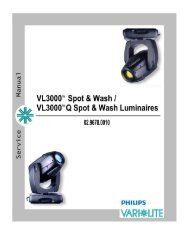
<strong>VL2000</strong> <strong>Spot</strong> <strong>Luminaire</strong><br />
The following illustration shows the major luminaire components and controls.<br />
Truss Hook<br />
Bracket Assembly<br />
Upper Enclosure<br />
Assembly<br />
Removable Lamp Assembly<br />
(to access lamp for replacement)<br />
AC Input Cable<br />
Yoke<br />
Assembly<br />
Head Assembly<br />
Beam Adjustment Controls<br />
Vertical<br />
Horizontal<br />
Focus<br />
Captive Knob<br />
for lamp access<br />
(does not adjust<br />
beam)<br />
Input Panel Components<br />
Product Label ID<br />
Main Power<br />
Switch<br />
Power and Data<br />
LED Indicators<br />
Menu Display<br />
AC Input Cable<br />
Data In<br />
Data Thru<br />
Figure 1-2: External Components and Controls<br />
6 02-May-03 02.9673.0001 D
DESCRIPTION : COMPONENTS<br />
1<br />
LED Indicators<br />
The LED indicators report the status of power and data to the luminaire.<br />
Indicates DC power is being<br />
supplied via AC Input when lit<br />
Indicates data is being<br />
transmitted when flashing<br />
Indicates data is being<br />
received when flashing fast;<br />
when flashing in 2 sec. heartbeat,<br />
indicates luminaire is idle<br />
Figure 1-3: LED Indicator Overview<br />
02.9673.0001 D 02-May-03 7
VARI❋LITE® - <strong>VL2000</strong> SPOT LUMINAIRE USER’S MANUAL<br />
Notes<br />
8 02-May-03 02.9673.0001 D
CHAPTER 2.<br />
Installation<br />
This chapter contains instructions for installation of the luminaire. It includes connecting power<br />
and data, along with instructions for powering up the luminaire for the first time and addressing<br />
it within your system.<br />
• Power and Data Cabling Requirements<br />
• Installation Procedures<br />
• Powering Up<br />
• Addressing<br />
02.9673.0001 D 02-May-03 9
VARI❋LITE® - <strong>VL2000</strong> SPOT LUMINAIRE USER’S MANUAL<br />
Power and Data Cabling Requirements<br />
Power<br />
The luminaire requires standard AC power distribution from 100-240 VAC, 50/60 Hz. Three amps to<br />
twelve amps will be required depending on the AC supply voltage and product model.<br />
Depending on the application, the luminaire’s AC input cable may require a different connector. If<br />
required, install a new connector meeting your requirements using the following wire color code<br />
reference:<br />
Wire*<br />
Green/Yellow<br />
Blue<br />
Brown<br />
Connection<br />
AC Ground<br />
AC Neutral<br />
AC Line<br />
* International (Harmonized) Standard<br />
WARNING: DO NOT connect to three-phase service in countries with 240 volt power.<br />
For single-phase power at 100 to 240 volts RMS:<br />
Connection<br />
AC Neutral<br />
AC Line<br />
Pin<br />
X<br />
Y<br />
X<br />
G<br />
Ground (Earth)<br />
G<br />
Y<br />
For three-phase power at 208 volts RMS:<br />
Connection<br />
Phase 1<br />
Phase 2<br />
Pin<br />
X<br />
Y<br />
X<br />
G<br />
Ground (Earth)<br />
G<br />
Y<br />
10 02-May-03 02.9673.0001 D
INSTALLATION : POWER AND DATA CABLING REQUIREMENTS<br />
2<br />
Current vs. Voltage<br />
The following table provides the luminaire’s current draw at specific voltages. Current is calculated<br />
with the lamp on and all motors sequencing.<br />
Table 2-1: Current vs. Voltage<br />
Voltage @ 60Hz Current<br />
90.0 11.8<br />
100.0 10.6<br />
110.0 9.5<br />
120.0 8.5<br />
130.0 7.9<br />
140.0 7.2<br />
180.0 5.5<br />
190.0 5.2<br />
200.0 4.9<br />
210.0 4.7<br />
220.0 4.5<br />
230.0 4.3<br />
240.0 4.1<br />
250.0 3.9<br />
02.9673.0001 D 02-May-03 11
VARI❋LITE® - <strong>VL2000</strong> SPOT LUMINAIRE USER’S MANUAL<br />
Data Cables<br />
The luminaire is equipped with two, 5-pin XLR connectors for DATA IN and DATA THRU (out)<br />
applications. DATA IN requires a 5-pin, female XLR connector and DATA THRU requires a 5-pin,<br />
male XLR connector. When purchasing or constructing data cables, it is important that not only the<br />
correct cable type be used, but also quality cable to ensure a reliable DMX512 system. Your cabling<br />
should meet the following USITT DMX specification requirements:<br />
• Suitable for use with EIA485 (RS485) operation at 250k baud.<br />
• Characteristic impedance 85-150 ohms, nominally 120 ohms.<br />
• Low capacitance.<br />
• Two twisted pairs.<br />
• Foil and braid shielded.<br />
• 24 AWG min. gauge for runs up to 1000 feet (300m).<br />
• 22 AWG min. gauge for runs up to 1640 feet (500m).<br />
Note: Microphone type cables and other general purpose, two-core audio or signal cables are not<br />
suitable for use with DMX512.<br />
Refer to the USITT Recommended Practice for DMX512 guide for additional information regarding<br />
DMX512 systems. How to obtain a copy is detailed in “Additional Documentation” on page 1.<br />
The XLR 5-pin connectors should be wired as follows:<br />
Data Thru<br />
Cable Pinout<br />
1<br />
2 4<br />
3<br />
Male Conn<br />
Pin 1<br />
Foil &<br />
Braided<br />
Shield<br />
Pin/Wire Code to XLR Connectors<br />
Pin 2<br />
1st<br />
conductor<br />
of 1st<br />
twisted<br />
pair<br />
Data (-)<br />
Pin 3<br />
2nd<br />
conductor<br />
of 1st<br />
twisted<br />
pair<br />
Data (+)<br />
Pin 4<br />
1st<br />
conductor<br />
of 2nd<br />
twisted<br />
pair<br />
Data (-)<br />
Pin 5<br />
2nd<br />
conductor<br />
of 2nd<br />
twisted<br />
pair<br />
Data (+)<br />
Data In<br />
Cable Pinout<br />
5 5<br />
1<br />
4 2<br />
3<br />
Female Conn<br />
12 02-May-03 02.9673.0001 D
INSTALLATION : POWER AND DATA CABLING REQUIREMENTS<br />
2<br />
Recommended Cable Types/Manufacturers<br />
These are only a few of the suitable cable types. Any quality EIA485, twisted pair, 120 ohm, shielded<br />
cable will also work.<br />
Type Pairs ZΩ ∗ Jacket AWG Use Temp (F)<br />
Belden Cables<br />
1215A 2 150 PVC 26 IBM Type 6 75<br />
Office cable<br />
1269A 2 100 PTFE 22 (Solid) High Temp, Plenum<br />
200<br />
cable<br />
8102 2 100 PVC 24 UL2919 80<br />
8132 2 120 PVC 28 UL2919 80<br />
8162 2 100 PVC 24 UL2493 60<br />
82729 2 100 PTFE 24 High Temp, Plenum<br />
200<br />
cable<br />
88102 2 100 PTFE 24 High Temp, Plenum<br />
200<br />
cable<br />
89696 2 100 PTFE 22 High Temp, Plenum<br />
200<br />
cable<br />
89729 2 100 PTFE 24 High Temp, Plenum<br />
200<br />
cable<br />
89855 2 100 PTFE 22 High Temp, Plenum<br />
200<br />
cable<br />
9729 2 100 PVC 24 UL2493 60<br />
9804 2 100 PVC 28 UL2960 60<br />
9829 2 100 PVC 24 UL2919 80<br />
9842 2 120 PVC 24 UL2919 80<br />
PC224P 2 110 Polyurethane<br />
Proplex Cables<br />
22 Heavy Duty and<br />
Portable<br />
PC224T 2 110 PVC 22 UL2464 105<br />
PC226T 3 110 PVC 22 UL2464<br />
105<br />
* Characteristic Impedance<br />
02.9673.0001 D 02-May-03 13
VARI❋LITE® - <strong>VL2000</strong> SPOT LUMINAIRE USER’S MANUAL<br />
Male Termination Connector<br />
A male XLR termination connector is required at the last luminaire (or "far<br />
end of the line") to prevent signal reflections. Signal reflections may cancel<br />
out the signal at certain line lengths, resulting in errors. The terminator is also<br />
necessary for software downloads and running tests on multiple luminaires.<br />
To construct your own connector, you will need the following components:<br />
• 5-pin, male XLR connector.<br />
• Two 1/4W 5% 120 ohm resistors.<br />
1<br />
2 4<br />
3<br />
Solder resistors across<br />
pins 2 & 3, and 4 & 5<br />
5<br />
Note: A male termination connector is available as an accessory from <strong>Vari</strong>-<strong>Lite</strong>. See “Replacement<br />
Items/Accessories” on page 5.<br />
Loopback Connector<br />
When transferring software versions from luminaire to luminaire, a<br />
loopback connector is required at the first luminaire in the data link.<br />
To construct your own connector, you will need the following<br />
components:<br />
• 5-pin, female XLR connector.<br />
• Two small segments of 22AWG wire.<br />
5<br />
4<br />
3<br />
Solder wires across<br />
pins 2 & 4, and 3 & 5<br />
2<br />
1<br />
Note: A loopback connector is available as an accessory from <strong>Vari</strong>-<strong>Lite</strong>. See “Replacement Items/<br />
Accessories” on page 5.<br />
14 02-May-03 02.9673.0001 D
INSTALLATION : INSTALLATION PROCEDURES<br />
2<br />
Installation Procedures<br />
Installing Lamp<br />
In the event the lamp was packed separately during shipment, it will be necessary to install in the<br />
luminaire before use.<br />
WARNING: Ensure that power is removed from luminaire when installing lamp.<br />
CAUTION: Wear cotton gloves or other covering while installing lamp. Touching lamp glass with<br />
bare fingers will leave oil and may cause the lamp to explode or reduce lamp life. If touched, use<br />
alcohol and cotton cloth to thoroughly clean glass portion of lamp.<br />
To install lamp:<br />
Step 1. Ensure power is removed from luminaire.<br />
Step 2. Remove lamp from shipping box.<br />
Step 3. At backcap, using slotted screwdriver (or fingers) turn<br />
captive knob until loose.<br />
Step 4. Slide backcap away from head assembly (it will remain<br />
attached by tether and lamp wires.).<br />
CAUTION:<br />
Ensure lamp is seated<br />
straight in socket before<br />
re-installing backcap.<br />
Backcap Assembly<br />
Captive Knob<br />
Lamp<br />
<strong>Guide</strong> Rod<br />
Step<br />
Step<br />
Figure 2-1: Installing Lamp<br />
5. Install lamp by pressing into socket. Ensure lamp is fully seated in socket and parallel to<br />
guide rods. (Lamp can be damaged when inserted through reflector if not parallel to guide<br />
rods.)<br />
6. Align guide rods in guide holes and slide backcap into head assembly. Re-tighten captive<br />
knob.<br />
Note: After installing a new lamp, it is necessary to adjust the beam for optimum performance. This<br />
procedure is covered in “Powering Up” on page 20.<br />
02.9673.0001 D 02-May-03 15
VARI❋LITE® - <strong>VL2000</strong> SPOT LUMINAIRE USER’S MANUAL<br />
Hanging the <strong>Luminaire</strong><br />
The <strong>VL2000</strong> spot luminaire can be hung horizontally or vertically from any structure designed to work<br />
with the type of load created by this moving luminaire. Two mounting bracket assemblies (provided)<br />
are used to attach truss hooks or other mounting hardware as required. Many compatible truss hooks<br />
are available from different manufacturers for your particular needs.<br />
A minimum of one hook per truss hook bracket is required. If mounting method does not use truss<br />
hooks, two attachment points per truss hook bracket are required. When attaching more than one point<br />
on a single bracket, the attach points must be spaced as far apart as possible using the supplied<br />
mounting holes.<br />
Install mounting hardware and brackets:<br />
Step 1. Install truss hooks on two provided truss hook brackets as required.<br />
Bracket<br />
Mega Claw Truss Hook<br />
(not provided)<br />
Example Truss<br />
Hook Installation<br />
Truss Hook Hardware<br />
(not provided)<br />
Figure 2-2: Installing Truss Hooks<br />
Note: <strong>Vari</strong>ous types of truss hooks can be used. The Mega Claw truss hook (as shown in the example<br />
above) as well as many other standard hooks, can be ordered separately.<br />
Step<br />
2. Determine required configuration of bracket installation. Brackets may be installed in either<br />
orientation as shown.<br />
Bracket<br />
Figure 2-3: Bracket Orientation Options<br />
16 02-May-03 02.9673.0001 D
INSTALLATION : INSTALLATION PROCEDURES<br />
2<br />
Step<br />
3. While pulling up on locking mechanism release, fit keyed holes onto raised mounting<br />
buttons at bottom of enclosure. Slide forward and release locking mechanism to lock in<br />
place. Ensure brackets are locked securely. (Always face brackets in same direction as<br />
shown.)<br />
WARNING: Ensure that the bracket locking mechanism is fully seated after the bracket is installed<br />
on the luminaire.<br />
Locking Mechanism<br />
Truss Hook Bracket<br />
Keyed Hole<br />
Press up when<br />
installing or releasing<br />
Face brackets in<br />
same direction for<br />
all configurations<br />
Raised Mounting Button<br />
Once fitted over buttons,<br />
slide forward to lock<br />
in place<br />
Locked<br />
Figure 2-4: Installing Brackets on <strong>Luminaire</strong> Enclosure<br />
02.9673.0001 D 02-May-03 17
VARI❋LITE® - <strong>VL2000</strong> SPOT LUMINAIRE USER’S MANUAL<br />
Installing in Truss:<br />
Step 1. Using two people, lift luminaire into mounting position.<br />
Step 2. Secure in place with truss hook. Ensure truss hook hardware that locks hook in place (e.g.<br />
wing bolt) is properly tightened and that luminaire is fully supported.<br />
Step 3. Attach safety cable (as required) as follows:<br />
a. Connect one end of cable to luminaire handle.<br />
b. Loop at least once around truss/pipe and attach other end of cable to other handle.<br />
Step 4. Connect power and data cables according to procedure given in “Connecting Data and<br />
Power” on page 19.<br />
Safety Cable:<br />
Recommended for hanging installations.<br />
May be required by local codes.<br />
19”<br />
(48.3cm)<br />
**<br />
25.375”<br />
(64.5cm)<br />
17.25”<br />
(43.8cm)<br />
Handles are<br />
approved for<br />
safety cable<br />
anchor points<br />
*<br />
27.125”<br />
(68.9cm)<br />
* From lens to top of bracket<br />
**<br />
From lens to base of enclosure<br />
***<br />
18.5”<br />
(47cm)<br />
Figure 2-5: Hanging Dimensions and Clearances<br />
***<br />
Head Swing<br />
Diameter<br />
18 02-May-03 02.9673.0001 D
INSTALLATION : INSTALLATION PROCEDURES<br />
2<br />
Floor Mounting the <strong>Luminaire</strong><br />
The luminaire enclosure is sufficient to stabilize the luminaire in a floor installation, provided that the<br />
mounting surface is flat and sturdy.<br />
Connecting Data and Power<br />
A maximum of 32 luminaires may be connected in any one DMX data link.<br />
Note: This maximum limit applies to the luminaire "daisy chain" only. Your system or console may<br />
require fewer luminaires on a single data link path. Consult your console documentation for more<br />
information.<br />
To connect power and data:<br />
Step 1. Connect data cable from console to first luminaire in chain at DATA IN connector.<br />
Step 2. If required, connect additional data cables from DATA THRU connectors to DATA IN<br />
connectors of remaining luminaires in link.<br />
Step 3. At last luminaire in link, install male termination connector at DATA THRU connector.<br />
(<strong>Luminaire</strong>s and other devices on the same DMX chain may not function properly without<br />
termination.)<br />
Data Thru<br />
Data Thru<br />
Data In<br />
from console<br />
Termination<br />
Step<br />
Step<br />
Figure 2-6: Data Link<br />
4. Connect AC Input Cable connector to power input source.<br />
5. Dress AC input and data cables and secure them so that they will not interfere with<br />
luminaire head and yoke movement.<br />
02.9673.0001 D 02-May-03 19
VARI❋LITE® - <strong>VL2000</strong> SPOT LUMINAIRE USER’S MANUAL<br />
Powering Up<br />
Power-Up Procedure<br />
Since Lamp On is the default state, the lamp will strike when the luminaire is powered up for the first<br />
time. When AC power is applied, the luminaire will immediately begin a calibration sequence that<br />
steps it through full pan and tilt movements. The internal color, gobo, and beam mechanisms will also<br />
move through a full range of motion. After calibration, the luminaire head will either stop at its "home"<br />
position (which positions the pan axis at mid-rotation and the head parallel to the yoke with the lens<br />
pointing away from the luminaire upper enclosure) or move to its current DMX-defined position if<br />
DMX data is present. All internal mechanisms also move to their "home" or DMX-defined positions.<br />
Subsequently, depending on the luminaire’s setting for Lamp Power-Up State (refer to “Menu System<br />
Functions” on page 53), when power is applied, the arc lamp will either a) "strike" or ignite - Lamp On<br />
(default), b) await calibration and then strike - Cal On, or c) await manual command to strike - Lamp<br />
Off.<br />
CAUTION: Before applying power, be sure the luminaire is hung or positioned so that the head and<br />
yoke can move freely without restriction.<br />
To power up:<br />
Step 1. At each luminaire, apply power by switching power switch to "I" (ON) position. <strong>Luminaire</strong><br />
will automatically step through following procedure:<br />
a. If Lamp Power-Up State is set to Lamp On, lamp will strike (ignite).<br />
b. <strong>Luminaire</strong> will cycle through calibration and stop at "home" position.<br />
c. If Lamp Power-Up State is set to Cal On, lamp will strike (ignite) at end of calibration<br />
sequence.<br />
20 02-May-03 02.9673.0001 D
INSTALLATION : POWERING UP<br />
2<br />
Align Lamp for Flat Field<br />
The design of the <strong>VL2000</strong> spot luminaire optical system is based on a flat field. A flat field is one<br />
where there is no detectable hot spot.<br />
After a new lamp is installed, it will be necessary to align the lamp to optimize the beam for the flat<br />
field. Knobs located at the luminaire’s backcap will allow adjustment.<br />
WARNING: Backcap and adjustment knobs will be HOT during lamp operation. Wear gloves and/or<br />
use tools to prevent burns.<br />
To align lamp:<br />
Step 1. Using internal menus select Lamp test to set beam. See “Menu System Functions” on<br />
page 53 for more information. (If using console, set intensity to 100%, open beam size iris<br />
and focus for hard edge.)<br />
Step 2. Position beam on a white wall at a distance of 10' to 20'.<br />
Step 3. At backcap, using Vertical and Horizontal knobs, adjust hot spot to center of beam.<br />
Step 4. Using Focus knob, adjust beam for best spot.<br />
Vertical<br />
Horizontal<br />
Focus<br />
Captive Knob for lamp access<br />
(does not adjust beam)<br />
Figure 2-7: Lamp Alignment Controls<br />
02.9673.0001 D 02-May-03 21
VARI❋LITE® - <strong>VL2000</strong> SPOT LUMINAIRE USER’S MANUAL<br />
Set DMX Mode<br />
The luminaire provide four modes for DMX operation. The mode is set using the Menu Display.<br />
• 8-bit Standard - provides one 8-bit DMX channel for control of each luminaire function.<br />
• 8-bit Enhanced - provides additional channels for timing control.<br />
• 16-bit Standard - provides 16-bit control for pan/tilt.<br />
• 16-bit Enhanced (default) - provides 16-bit control for pan/tilt and additional channels for timing<br />
control.<br />
To set the mode:<br />
Step 1. Press [Menu].<br />
Step 2. Press [Up] or [Down] button until DMX appears. Press [Enter].<br />
Step 3. Press [Up] or [Down] to until desired mode is reached (8, 16, E 8, or E 16). Press [Enter]<br />
to set mode.<br />
See “DMX Modes” on page 28 for more information.<br />
Note: Which mode is used may also be determined by the profile available in the DMX control<br />
console. For best control, response, smoothest movement and transitions, the 16-bit Enhanced mode is<br />
recommended. The 8-bit modes are supported for older style consoles with a limited number of DMX<br />
channels available, and if profiles are not supported. The 16-bit mode is supported for DMX consoles<br />
that do not provide access to the timing channels through either their architecture or their profiles. For<br />
more information see “<strong>Luminaire</strong> Timing Channel Information” on page 34.<br />
22 02-May-03 02.9673.0001 D
INSTALLATION : ADDRESSING<br />
2<br />
Addressing<br />
Program Starting Address<br />
The address setting for DMX console or Virtuoso console controlled systems is entered using the<br />
Menu Display. (Refer to “Menu System” chapter on page 47 for detailed instructions.)<br />
The luminaire retains the DMX and Virtuoso addresses that are stored even if power is removed.<br />
Note: Refer to your console operating instructions for specific information regarding its addressing<br />
requirements.<br />
Program a DMX or Virtuoso starting address:<br />
Step 1. Press [Menu].<br />
Step 2. Press [Up] / [Down] arrows until ADDR (Address) appears. Press [Enter].<br />
Step 3. Press [Up] / [Down] arrows to access DMX (DMX console control) or VIRT (Virtuoso<br />
console control). Press [Enter].<br />
Step 4. Press [Up] / [Down] arrows to enter starting address.<br />
Step 5. Press [Enter] to set.<br />
Program Starting Address Without Calibrating the<br />
<strong>Luminaire</strong><br />
It is possible to bypass the calibration sequence and go directly to the Menu Display programming in<br />
order to pre-program an address setting.<br />
Program starting address without calibrating luminaire:<br />
• While powering up luminaire, press and hold [Menu]. Program address as in Program Starting<br />
Address above.<br />
Note: The luminaire will require a reset to restore control.<br />
02.9673.0001 D 02-May-03 23
VARI❋LITE® - <strong>VL2000</strong> SPOT LUMINAIRE USER’S MANUAL<br />
Notes<br />
24 02-May-03 02.9673.0001 D
CHAPTER 3.<br />
Operation<br />
This chapter contains instructions for operating the luminaire using DMX control and for<br />
updating the internal software.<br />
• Color/Gobo Control<br />
• DMX Modes<br />
• DMX Mapping<br />
• <strong>Luminaire</strong> Timing<br />
• Updating Software<br />
02.9673.0001 D 02-May-03 25
VARI❋LITE® - <strong>VL2000</strong> SPOT LUMINAIRE USER’S MANUAL<br />
Color/Gobo Control<br />
Color/Gobo Wheel Positions<br />
The standard configurations for color and fixed gobo wheels<br />
are: all color filters installed on Wheel 1 (wheel nearest lamp)<br />
and all gobos installed on Wheel 2 (wheel nearer to front lens).<br />
These wheels each have 12 positions, one being open.<br />
All rotating gobos are installed on the Rotating Gobo Wheel<br />
(nearest to front lens). This wheel has six positions, one being<br />
open.<br />
Color and gobo wheels offer partial frame control and various<br />
spin rates in either direction.<br />
Front Lens<br />
Wheel 1 - Colors<br />
(Behind plate)<br />
Color/Gobo/Iris<br />
Bulkhead<br />
Wheel 2 - Gobos<br />
Figure 3-1: Color/Gobo Bulkhead<br />
Standard Colors and Gobos<br />
The following illustrations show the color and gobo standard configurations.<br />
Standard Colors - Wheel 1 (Color Wheel)<br />
Light Red Blue Yellow Light Blue Pink<br />
3<br />
4<br />
5<br />
2<br />
6<br />
1<br />
7<br />
12<br />
8<br />
11<br />
10<br />
9<br />
UV Orange Amber Lavender Magenta<br />
Figure 3-2: Standard Colors - Wheel 1 (Color Wheel)<br />
Green<br />
26 02-May-03 02.9673.0001 D
OPERATION : COLOR/GOBO CONTROL<br />
3<br />
Standard Gobos - Wheel 2 (Fixed Gobo Wheel)<br />
Pebbles<br />
Dust<br />
Breakup<br />
Medium<br />
Circles<br />
Night Sky<br />
Leaves<br />
3<br />
4<br />
5<br />
2<br />
6<br />
1<br />
7<br />
12<br />
8<br />
11<br />
10<br />
9<br />
Alpha Liquid Tribal Block Wave Vertical<br />
Rays Breakup Breakup Breakup Bars<br />
Figure 3-3: Standard Gobos - Wheel 2 (Fixed Gobo Wheel)<br />
Standard Rotating Gobos<br />
open<br />
5 Facet Prism<br />
Pinwheel<br />
1<br />
6<br />
2<br />
5<br />
3<br />
4<br />
Spiral Stones<br />
Circle of Ovals<br />
Hypnospiral<br />
Figure 3-4: Standard Rotating Gobos<br />
02.9673.0001 D 02-May-03 27
VARI❋LITE® - <strong>VL2000</strong> SPOT LUMINAIRE USER’S MANUAL<br />
DMX Modes<br />
8-Bit and 16-Bit Modes<br />
These tables assume a DMX start address of 1. When a different starting address is used, this address<br />
becomes channel 1 function and other functions follow in sequence.<br />
Standard 8-Bit (8) Standard 16-Bit (16)<br />
Function DMX Channel Function DMX Channel<br />
Intensity 1 Intensity 1<br />
Pan 2 Pan 2 - 3<br />
Tilt 3 Tilt 4 - 5<br />
Fixed Gobo 4 Fixed Gobo 6<br />
Color 5 Color 7<br />
Iris 6 Iris 8<br />
Edge 7 Edge 9<br />
Strobe 8 Strobe 10<br />
Zoom 9 Zoom 11<br />
Rot Wheel 10 Rot Wheel 12<br />
Gobo Index 11 Gobo Index 13<br />
Control 12 Control 14<br />
Enhanced 8-Bit (E 8)<br />
Enhanced 16-Bit (E 16) - Default<br />
Function DMX Channel Function DMX Channel<br />
Intensity 1 Intensity 1<br />
Pan 2 Pan 2 - 3<br />
Tilt 3 Tilt 4 - 5<br />
Fixed Gobo 4 Fixed Gobo 6<br />
Color 5 Color 7<br />
Iris 6 Iris 8<br />
Edge 7 Edge 9<br />
Strobe 8 Strobe 10<br />
Zoom 9 Zoom 11<br />
Rot Wheel 10 Rot Wheel 12<br />
Gobo Index 11 Gobo Index 13<br />
Focus Timing 12 Focus Timing 14<br />
Color Timing 13 Color Timing 15<br />
Beam Timing 14 Beam Timing 16<br />
Control 15 Control 17<br />
28 02-May-03 02.9673.0001 D
OPERATION : DMX MAPPING<br />
3<br />
DMX Mapping<br />
Color and Gobo Control<br />
Color/Gobo Wheels<br />
Table 3-1: DMX Map For Color/Gobo Wheels<br />
% Value DMX (0-255) Wheel Position<br />
0 0 Open Frame 1<br />
1<br />
2<br />
1 3<br />
4<br />
2 5<br />
6<br />
7<br />
3 8<br />
9 Half Frame<br />
4 10<br />
11<br />
12<br />
5 13<br />
14<br />
6 15<br />
16<br />
17<br />
7 18 Full Frame 2<br />
19<br />
8 20<br />
21<br />
22<br />
9 23<br />
24<br />
10 25<br />
26 Half Frame<br />
27<br />
11 28<br />
29<br />
30<br />
12 31<br />
32<br />
13 33<br />
02.9673.0001 D 02-May-03 29
VARI❋LITE® - <strong>VL2000</strong> SPOT LUMINAIRE USER’S MANUAL<br />
Table 3-1: DMX Map For Color/Gobo Wheels (Continued)<br />
% Value DMX (0-255) Wheel Position<br />
34<br />
35<br />
14 36 Full Frame 3<br />
37<br />
15 38<br />
39<br />
40<br />
16 41<br />
42<br />
17 43<br />
44 Half Frame<br />
45<br />
18 46<br />
47<br />
19 48<br />
49<br />
50<br />
20 51<br />
52<br />
53<br />
21 54 Full Frame 4<br />
55<br />
22 56<br />
57<br />
58<br />
23 59<br />
60<br />
24 61<br />
62 Half Frame<br />
63<br />
25 64<br />
65<br />
26 66<br />
67<br />
68<br />
27 69<br />
70<br />
28 71<br />
72 Full Frame 5<br />
73<br />
29 74<br />
75<br />
30 02-May-03 02.9673.0001 D
OPERATION : DMX MAPPING<br />
3<br />
Table 3-1: DMX Map For Color/Gobo Wheels (Continued)<br />
% Value DMX (0-255) Wheel Position<br />
30 76<br />
77<br />
78<br />
31 79<br />
80 Half Frame<br />
81<br />
32 82<br />
83<br />
33 84<br />
85<br />
86<br />
34 87<br />
88<br />
35 89<br />
90 Full Frame 6<br />
91<br />
36 92<br />
93<br />
37 94<br />
96<br />
38 97<br />
98 Half Frame<br />
39 99<br />
100<br />
101<br />
40 102<br />
103<br />
104<br />
41 105<br />
106<br />
42 107<br />
108 Full Frame 7<br />
109<br />
43 110<br />
111<br />
44 112<br />
113<br />
114<br />
45 115<br />
116 Half Frame<br />
46 117<br />
118<br />
02.9673.0001 D 02-May-03 31
VARI❋LITE® - <strong>VL2000</strong> SPOT LUMINAIRE USER’S MANUAL<br />
Table 3-1: DMX Map For Color/Gobo Wheels (Continued)<br />
% Value DMX (0-255) Wheel Position<br />
119<br />
47 120<br />
121<br />
48 122<br />
123<br />
124<br />
49 125<br />
126 Full Frame 8<br />
127<br />
50 128<br />
129<br />
51 130<br />
131<br />
132<br />
52 133<br />
134 Half Frame<br />
53 135<br />
136<br />
137<br />
54 138<br />
139<br />
55 140<br />
141<br />
142<br />
56 143<br />
144 Full Frame 9<br />
57 145<br />
146<br />
147<br />
58 148<br />
149<br />
59 150<br />
151<br />
152 Half Frame<br />
60 153<br />
154<br />
155<br />
61 156<br />
157<br />
62 158<br />
159<br />
160<br />
32 02-May-03 02.9673.0001 D
OPERATION : DMX MAPPING<br />
3<br />
Table 3-1: DMX Map For Color/Gobo Wheels (Continued)<br />
% Value DMX (0-255) Wheel Position<br />
63 161<br />
162 Full Frame 10<br />
64 163<br />
164<br />
165<br />
65 166<br />
167<br />
66 168<br />
169<br />
170 Half Frame<br />
67 171<br />
172<br />
68 173<br />
174<br />
175<br />
69 176<br />
177<br />
178<br />
70 179<br />
180 Full Frame 11<br />
71 181<br />
182<br />
183<br />
72 184<br />
185<br />
73 186<br />
187<br />
188 Half Frame<br />
74 189<br />
190<br />
75 191<br />
192<br />
193<br />
76 194<br />
195<br />
77 196<br />
197 Full Frame 12<br />
198<br />
78 199<br />
200<br />
79 201<br />
202<br />
02.9673.0001 D 02-May-03 33
VARI❋LITE® - <strong>VL2000</strong> SPOT LUMINAIRE USER’S MANUAL<br />
Table 3-1: DMX Map For Color/Gobo Wheels (Continued)<br />
% Value DMX (0-255) Wheel Position<br />
203<br />
80 204<br />
205<br />
206 Half Frame<br />
81 207<br />
208<br />
82 209<br />
210<br />
211<br />
83 212<br />
213<br />
84 214<br />
215<br />
216 Spin F CCW<br />
85 217<br />
218<br />
86 219<br />
220<br />
221<br />
87 222<br />
223<br />
88 224<br />
225 Spin M CCW<br />
226<br />
89 227<br />
228<br />
229<br />
90 230<br />
231<br />
91 232<br />
233 Spin S CCW<br />
234 Stop<br />
92 235 Stop<br />
236 Stop<br />
93 237 Spin S CW<br />
238<br />
239<br />
94 240<br />
241<br />
95 242<br />
243<br />
244<br />
34 02-May-03 02.9673.0001 D
OPERATION : DMX MAPPING<br />
3<br />
Table 3-1: DMX Map For Color/Gobo Wheels (Continued)<br />
% Value DMX (0-255) Wheel Position<br />
96 245<br />
246 Spin M CW<br />
97 247<br />
248<br />
249<br />
98 250<br />
251<br />
99 252<br />
253<br />
254<br />
100 255 Spin F CW<br />
Rotating Gobo Index/Rotation<br />
Table 3-2: DMX Map for Gobo Index/Rotation<br />
% Value DMX (0-255) Wheel Position<br />
0-84 0-215 Index Position<br />
85 216 Fast Spin CW<br />
86-90 217-232 <strong>Vari</strong>able Rates<br />
91 233 Slow Spin CW<br />
92 234-237 Stop<br />
93 238 Slow Spin CCW<br />
94-99 239-254 <strong>Vari</strong>able Rates<br />
100 255 Fast Spin CCW<br />
Rotating Gobo Wheel<br />
Table 3-3: DMX Map for Rotating Gobo Wheel<br />
% Value DMX (0-255) Action<br />
0 0 Position 1 (Open)<br />
20 51 Position 2<br />
40 102 Position 3<br />
60 153 Position 4<br />
80 204 Position 5<br />
100 255 Position 6<br />
02.9673.0001 D 02-May-03 35
VARI❋LITE® - <strong>VL2000</strong> SPOT LUMINAIRE USER’S MANUAL<br />
Beam Control<br />
Beam Iris<br />
Table 3-4: DMX Map For Beam Iris<br />
% Value DMX Value Action<br />
0 0 Closed<br />
100 255 Open<br />
Edge<br />
Table 3-5: DMX Map For Edge<br />
% Value DMX Value Action<br />
0 0 Blooms In<br />
100 255 Blooms Out<br />
Strobe<br />
Table 3-6: DMX Map For Strobe<br />
% Value DMX Value Action<br />
0 0-2 Open<br />
1 3-5 Closed<br />
2 6-7 Slow Random<br />
3 8-10 Med Random<br />
4 11-12 Fast Random<br />
5-100 13-255 Speed Range<br />
Zoom<br />
Table 3-7: DMX Map For Zoom<br />
% Value DMX Value Action<br />
0 0 Narrow<br />
100 255 Wide<br />
36 02-May-03 02.9673.0001 D
OPERATION : LUMINAIRE TIMING<br />
3<br />
<strong>Luminaire</strong> Timing<br />
<strong>Luminaire</strong> Timing Channel Information<br />
Timing channel control improves the timed moves of certain groups of parameters. We provide three<br />
timing channels, one for Focus (Pan and Tilt), one for color parameters and one for beam parameters.<br />
Timing channels support time values of up to six minutes.<br />
Table 3-8: Channel Function / Timing Channel Relationship<br />
Channel Function<br />
Pan (Hi Byte/Lo Byte)<br />
Tilt (Hi Byte/Lo Byte)<br />
Color<br />
Gobo<br />
Rotating Gobo<br />
Index<br />
Iris<br />
Edge<br />
Zoom<br />
Timing Channel<br />
Focus Time Color Time Beam Time<br />
<br />
<br />
<br />
<br />
<br />
<br />
<br />
<br />
<br />
A timing value of zero is full speed. A time value of 100% (or 255 in DMX) causes the associated<br />
parameter(s) to follow cue fade time (console time) rather than the timing channel.<br />
Note: The particular storing syntax for your console, as well as instructions on how to write part cues,<br />
can be found in the operation manual for that console.<br />
To use these channels, you must:<br />
Step 1. Create the cue, including color, gobo, edge and diffusion as required.<br />
Step 2. Decide which fixtures and which parameter groups will use timing channels.<br />
Step 3. Assign a value to the particular timing channel(s) you wish to use (for timing information<br />
see chart on next page).<br />
Step 4. Set console timing (or cue fade time) for parameters and timing channels to zero seconds.<br />
Step 5. Store cue.<br />
Note: Avoid changing timing channel values in a fading cue. This can cause unexpected behavior in<br />
the luminaire as the timing channel value is updated over time. Timing channel values and the final<br />
destination of the parameters affected by the timing channel should always be sent in a zero count.<br />
Timing channels can be set in either % or 0-255 (DMX) modes, with the following values assigned:<br />
02.9673.0001 D 02-May-03 37
VARI❋LITE® - <strong>VL2000</strong> SPOT LUMINAIRE USER’S MANUAL<br />
Table 3-9: Timing Channels Map<br />
% Value DMX = Seconds<br />
0 Full Speed<br />
1 0.2<br />
2 0.4<br />
1 3 0.6<br />
4 0.8<br />
2 5 1<br />
6 1.2<br />
7 1.4<br />
3 8 1.6<br />
9 1.8<br />
4 10 2<br />
11 2.2<br />
12 2.4<br />
5 13 2.6<br />
14 2.8<br />
6 15 3<br />
16 3.2<br />
17 3.4<br />
7 18 3.6<br />
19 3.8<br />
8 20 4<br />
21 4.2<br />
22 4.4<br />
9 23 4.6<br />
24 4.8<br />
10 25 5<br />
26 5.2<br />
27 5.4<br />
11 28 5.6<br />
29 5.8<br />
30 6<br />
12 31 6.2<br />
32 6.4<br />
13 33 6.6<br />
34 6.8<br />
35 7.0<br />
14 36 7.2<br />
37 7.4<br />
15 38 7.6<br />
39 7.8<br />
38 02-May-03 02.9673.0001 D
OPERATION : LUMINAIRE TIMING<br />
3<br />
Table 3-9: Timing Channels Map (Continued)<br />
% Value DMX = Seconds<br />
40 8<br />
16 41 8.2<br />
42 8.4<br />
17 43 8.6<br />
44 8.8<br />
45 9<br />
18 46 9.2<br />
47 9.4<br />
19 48 9.6<br />
49 9.8<br />
50 10<br />
20 51 10.2<br />
52 10.4<br />
53 10.6<br />
21 54 11<br />
55 11<br />
22 56 12<br />
57 12<br />
58 13<br />
23 59 13<br />
60 14<br />
24 61 14<br />
62 14<br />
63 15<br />
25 64 15<br />
65 16<br />
26 66 16<br />
67 16<br />
68 17<br />
27 69 17<br />
70 18<br />
28 71 18<br />
72 18<br />
73 19<br />
29 74 19<br />
75 20<br />
30 76 20<br />
77 20<br />
78 21<br />
31 79 21<br />
80 21<br />
81 22<br />
02.9673.0001 D 02-May-03 39
VARI❋LITE® - <strong>VL2000</strong> SPOT LUMINAIRE USER’S MANUAL<br />
Table 3-9: Timing Channels Map (Continued)<br />
% Value DMX = Seconds<br />
32 82 22<br />
83 23<br />
33 84 23<br />
85 23<br />
86 24<br />
34 87 24<br />
88 25<br />
35 89 25<br />
90 25<br />
91 26<br />
36 92 26<br />
93 27<br />
37 94 27<br />
95 27<br />
96 28<br />
38 97 28<br />
98 29<br />
39 99 29<br />
100 29<br />
101 30<br />
40 102 30<br />
103 30<br />
104 31<br />
41 105 31<br />
106 32<br />
42 107 32<br />
108 32<br />
109 33<br />
43 110 33<br />
111 34<br />
44 112 34<br />
113 34<br />
114 35<br />
45 115 35<br />
116 36<br />
46 117 36<br />
118 36<br />
119 37<br />
47 120 37<br />
121 38<br />
48 122 38<br />
123 38<br />
40 02-May-03 02.9673.0001 D
OPERATION : LUMINAIRE TIMING<br />
3<br />
Table 3-9: Timing Channels Map (Continued)<br />
% Value DMX = Seconds<br />
124 39<br />
49 125 39<br />
126 39<br />
127 40<br />
50 128 40<br />
129 41<br />
51 130 41<br />
131 41<br />
132 42<br />
52 133 42<br />
134 43<br />
53 135 43<br />
136 43<br />
137 44<br />
54 138 44<br />
139 45<br />
55 140 45<br />
141 45<br />
142 46<br />
56 143 46<br />
144 47<br />
57 145 47<br />
146 47<br />
147 48<br />
58 148 48<br />
149 49<br />
59 150 49<br />
151 49<br />
152 50<br />
60 153 50<br />
154 50<br />
155 51<br />
61 156 51<br />
157 52<br />
62 158 52<br />
159 52<br />
160 53<br />
63 161 53<br />
162 54<br />
64 163 54<br />
164 54<br />
165 55<br />
02.9673.0001 D 02-May-03 41
VARI❋LITE® - <strong>VL2000</strong> SPOT LUMINAIRE USER’S MANUAL<br />
Table 3-9: Timing Channels Map (Continued)<br />
% Value DMX = Seconds<br />
65 166 55<br />
167 56<br />
66 168 56<br />
169 56<br />
170 57<br />
67 171 57<br />
172 58<br />
68 173 58<br />
174 58<br />
175 59<br />
69 176 59<br />
177 59<br />
178 60<br />
70 179 60<br />
180 65<br />
71 181 65<br />
182 65<br />
183 70<br />
72 184 70<br />
185 75<br />
73 186 75<br />
187 75<br />
188 80<br />
74 189 80<br />
190 85<br />
75 191 85<br />
192 85<br />
193 90<br />
76 194 90<br />
195 95<br />
77 196 95<br />
197 95<br />
198 100<br />
78 199 100<br />
200 110<br />
79 201 110<br />
202 110<br />
203 120<br />
80 204 120<br />
205 120<br />
81 206 130<br />
207 130<br />
42 02-May-03 02.9673.0001 D
OPERATION : LUMINAIRE TIMING<br />
3<br />
Table 3-9: Timing Channels Map (Continued)<br />
% Value DMX = Seconds<br />
208 140<br />
82 209 140<br />
210 140<br />
211 150<br />
83 212 150<br />
213 160<br />
84 214 160<br />
215 160<br />
216 170<br />
85 217 170<br />
218 180<br />
86 219 180<br />
220 180<br />
221 190<br />
87 222 190<br />
223 200<br />
88 224 200<br />
225 200<br />
226 210<br />
89 227 210<br />
228 210<br />
229 220<br />
90 230 220<br />
231 230<br />
91 232 230<br />
233 230<br />
234 240<br />
92 235 240<br />
236 250<br />
93 237 250<br />
238 250<br />
239 260<br />
94 240 260<br />
241 270<br />
95 242 270<br />
243 270<br />
244 280<br />
96 245 280<br />
246 290<br />
97 247 290<br />
248 290<br />
249 300<br />
02.9673.0001 D 02-May-03 43
VARI❋LITE® - <strong>VL2000</strong> SPOT LUMINAIRE USER’S MANUAL<br />
Table 3-9: Timing Channels Map (Continued)<br />
% Value DMX = Seconds<br />
98 250 300<br />
251 310<br />
99 252 310<br />
253 310<br />
254 310<br />
100 255 Follows Cue Data<br />
Control Channel Functions<br />
The following control actions must be accomplished with zero time transition or with timing disabled.<br />
Discrete values must be used and not manual controls such as faders or encoders.<br />
Table 3-10: Control Channel Functions<br />
Control<br />
Channel<br />
Function<br />
% Value<br />
Control Channel Value<br />
For 3 Secs<br />
or Greater<br />
After<br />
3 Secs<br />
Display On 1 1-4 0<br />
<strong>Luminaire</strong> Reset 33 81 - 87 0<br />
Lamp Off 66 165 - 171 0<br />
Lamp On 99 249 - 255 0<br />
To use control channel functions:<br />
Step 1. Select an action to be sent.<br />
Step 2. Set control channel value for desired action (for example, 84 for reset). Hold value for 3<br />
seconds.<br />
Note: A numerical keypad is required for sending values. An encoder or fader does not allow for a<br />
“snap” value change, which is required to affect the control functions.<br />
Step<br />
3. Set control channel value to zero. (This must occur without any scaling values. Action will<br />
be voided if other values are detected between action value and zero.)<br />
44 02-May-03 02.9673.0001 D
OPERATION : UPDATING SOFTWARE<br />
3<br />
Updating Software<br />
Reprogramming <strong>Luminaire</strong>s<br />
In some cases, it may be desirable to upgrade the luminaire’s operating software. This process requires<br />
a PC, VLDownload.exe, .bin files and the <strong>Luminaire</strong> Programming Kit (28.9661.0054).<br />
Components Overview<br />
Computer Requirements<br />
• PC running Windows 95/98, Windows NT (4.0 or higher), or Windows 2000. (Program is not<br />
compatible with Macintosh computers.)<br />
• Serial communication port. (RS-232 only, USB not supported.)<br />
VL Download Program<br />
The VL Download.exe program allows you to transfer new versions of the operating software (.bin<br />
files) to the luminaires via the PC. The VL Download.exe and current .bin files are available from the<br />
Product Downloads page at www.vari-lite.com. Instructions for installing the program on your PC are<br />
also available on the Product Downloads page.<br />
<strong>Luminaire</strong> Programming Kit<br />
The luminaire programming kit allows you to connect your PC to the luminaire chain in order to<br />
update software.<br />
<strong>Luminaire</strong> Programming Kit (28.9661.0054) components:<br />
• 6-Ft. Serial Straight Thru DB9M-F Cable (46.6033.0006)<br />
• RS-232 to RS-485 Interface Converter (46.6036.0001)<br />
• 6-Ft. RJ45 to 5-Pin Female XLR Cable (25.9661.0055)<br />
02.9673.0001 D 02-May-03 45
VARI❋LITE® - <strong>VL2000</strong> SPOT LUMINAIRE USER’S MANUAL<br />
Reprogramming Procedure<br />
Note: Up to 32 luminaires can be programmed at the same time if they are data linked together. Refer<br />
to “Connecting Data and Power” on page 19. (Programming more than 32 luminaires will require<br />
programming in batches of 32 or less.)<br />
To update luminaire software:<br />
Step 1. From Product Downloads page at www.vari-lite.com, download and install the<br />
VLDownload.exe program and required .bin files onto your PC (following instructions at the<br />
website).<br />
Step 2. Assemble <strong>Luminaire</strong> Programming Kit components by connecting Serial Straight Thru<br />
Cable and RJ45-to-XLR cable to Interface Converter.<br />
Step<br />
Step<br />
Step<br />
Step<br />
PC<br />
Serial Straight<br />
Thru Cable<br />
Interface Converter<br />
RJ45-to-XLR Cable<br />
<strong>Luminaire</strong><br />
(DMX In)<br />
Figure 3-5: Hardware Setup<br />
3. Connect Serial Straight Thru cable to serial Comm Port of PC and connect RJ45-to-XLR<br />
cable to DMX In connector of luminaire.<br />
4. Apply power to PC and luminaire(s).<br />
5. Run VLDownload.exe program by selecting from Start menu Programs list or by selecting<br />
from C:\ProgramFiles\<strong>Vari</strong>-<strong>Lite</strong>\VLDownload Program directory. (<strong>Luminaire</strong> Software<br />
Download window will open.)<br />
6. At Select Comm Port section of window (refer to Figure 3-6 on next page), select serial<br />
Comm Port (Comm Port 1, Comm Port 2, Comm Port 3, or Comm Port 4) where Serial<br />
Straight Thru Cable is connected.<br />
Note: DMX Data must be disconnected before downloading software to luminaires. (Do not merge<br />
with DMX signal.)<br />
Step<br />
7. At Select Software to Download section of window, select required luminaire<br />
software version to download by clicking its button or select Download All. (Software<br />
version is identified by the date and time: MM/DD/YY and HH:MM.) The buttons function<br />
as follows:<br />
<strong>VL2000</strong><strong>Spot</strong> button downloads the software to all <strong>VL2000</strong> spot luminaires.<br />
Download All button is the equivalent of executing all of the specific software version<br />
buttons shown in the window (if applicable). They will be executed one at a time in the order<br />
they appear in the window. This button can be used when any combination of VARI❋LITE<br />
luminaires are connected to the PC.<br />
46 02-May-03 02.9673.0001 D
OPERATION : UPDATING SOFTWARE<br />
3<br />
Note: Version dates shown in this graphic are for illustration purposes only and may not correspond to<br />
the version you are downloading.<br />
Click to download all<br />
listed software versions<br />
to connected luminaire(s)<br />
Click to download specific software<br />
version to connected luminaire(s)<br />
Lists the specific versions<br />
of software that have been<br />
downloaded<br />
Select PC serial<br />
port where cable<br />
is connected.<br />
Will show current<br />
progress of download<br />
Step<br />
Correct<br />
Trouble<br />
Step<br />
Figure 3-6: Download Interface Window<br />
8. Download will proceed. One of the following will occur:<br />
<strong>Luminaire</strong>’s green Rx LED will blink rapidly and its menu will display number of blocks<br />
received (this number will vary depending on software version being downloaded). This<br />
indicates that data is being sent from PC to luminaire. However, if display does not show<br />
blocks as they are received, this indicates that the version being downloaded matches the<br />
one already installed or that the luminaire type does not match.<br />
If luminaire’s green Rx LED does not blink rapidly and its menu does not display blocks,<br />
this indicates that no data is being received. (Check cable connections, port selection, etc.<br />
and try again.)<br />
9. Click Close to exit.<br />
Note: The History section of the window shows what specific types of luminaire software have been<br />
downloaded since the beginning of the session (window will reset once the program is closed and reopened).<br />
02.9673.0001 D 02-May-03 47
VARI❋LITE® - <strong>VL2000</strong> SPOT LUMINAIRE USER’S MANUAL<br />
Verify software version at luminaire:<br />
Step<br />
Step<br />
Step<br />
1. At Menu Display, press [Menu].<br />
2. Press [Up] / [Down] arrows until Fixt appears. Press [Enter].<br />
3. Press [Up] / [Down] arrows until Ver appears. Press [Enter].<br />
The first half of the version date will be displayed as MM/DD/YY (month/day/year): For<br />
example, 07/21/02 = July 21, 2002<br />
Press [Up] / [Down] arrows to display second half of version date.<br />
The second half of the version date will be displayed as XXX (time in 6 minute intervals):<br />
For example, 36.0 = 36 minutes<br />
Transferring Software From <strong>Luminaire</strong> to <strong>Luminaire</strong><br />
It is possible to transfer specific software versions between luminaires. As in the case of installing new<br />
software versions, multiple luminaires can be programmed at the same time if they are data linked<br />
together (refer to “Connecting Data and Power” on page 19), however a maximum of 32 luminaires<br />
can be updated at once.<br />
The transfer process can be used to download an earlier or later version of the <strong>Luminaire</strong> Software to<br />
other connected luminaires.<br />
Hardware Requirements<br />
Data cables used in this process must have two twisted pairs and a shield. It is also recommended that<br />
cables meet all other USITT DMX specification requirements. Refer to “Data Cables” on page 12.<br />
Loopback and termination connectors are used in this process. Refer to “Male Termination<br />
Connector” on page 14 for more information regarding the construction of these connectors.<br />
Transfer Procedure<br />
This procedure is used to transfer software versions between luminaires.<br />
Step 1. At master luminaire (first in link), install loopback connector into DATA IN XLR<br />
connector.<br />
Step 2. At last luminaire, install male termination connector into DATA THRU XLR connector.<br />
Master luminaire containing<br />
software version to download<br />
<strong>Luminaire</strong> 1<br />
requiring update<br />
<strong>Luminaire</strong> 2<br />
requiring update<br />
Loopback Connector<br />
Data Thru<br />
Data Thru<br />
Termination Connector<br />
Figure 3-7: Software Transfer Setup<br />
48 02-May-03 02.9673.0001 D
OPERATION : UPDATING SOFTWARE<br />
3<br />
Step<br />
Step<br />
Step<br />
Step<br />
Step<br />
Correct<br />
Trouble<br />
3. At master luminaire Menu Display, press [Menu].<br />
4. Press [Up] / [Down] arrows until Fixture appears.<br />
5. Press [Up] / [Down] arrows until Download appears. Press [Enter].<br />
6. OK will be displayed. Press [Enter] to accept.<br />
7. Download will proceed. (Download will take 1-2 seconds.) One of the following will occur:<br />
The receiving luminaire’s green Rx LED will blink rapidly and its menu will display<br />
number of blocks received (this number will vary depending on software version being<br />
downloaded). This indicates that data is being sent from luminaire to luminaire. However, if<br />
display does not show blocks as they are received, this indicates that the version being<br />
downloaded matches the one already installed or that the luminaire type does not match.<br />
If the receiving luminaire’s green Rx LED does not blink rapidly and its menu does not<br />
display blocks, this indicates that no data is being received. (Check cable connections,<br />
Loopback Connector, etc. and ensure ALL cabling is the 5-conductor type.)<br />
Note: Without any data connected, the normal standby cycle of the Rx LED is 2 sec on, 2 sec off.<br />
Note: The number of blocks displayed will be less in a luminaire-to-luminaire download than in a PCto-luminaire<br />
download for the same software version.<br />
Step 8. Once download is complete, luminaire will automatically recalibrate. Once recalibration is<br />
complete, luminaire is ready for operation with its new software version.<br />
Verify software version at luminaire:<br />
Step 1. At Menu Display, press [Menu].<br />
Step 2. Press [Up] / [Down] arrows until Fixt appears. Press [Enter].<br />
Step 3. Press [Up] / [Down] arrows until Ver appears. Press [Enter].<br />
The first half of the version date will be displayed as MM/DD/YY (month/day/year): For<br />
example, 07/21/02 = July 21, 2002<br />
Press [Up] / [Down] arrows to display second half of version date.<br />
The second half of the version date will be displayed as XXX (time in 6 minute intervals):<br />
For example, 36.0 = 36 minutes<br />
02.9673.0001 D 02-May-03 49
VARI❋LITE® - <strong>VL2000</strong> SPOT LUMINAIRE USER’S MANUAL<br />
Notes<br />
50 02-May-03 02.9673.0001 D
CHAPTER 4.<br />
Menu System<br />
This chapter contains instructions for operating the luminaire using the Menu Display feature.<br />
• Operation<br />
• Display TestMapping<br />
• Cues and Sequences<br />
• Self Tests<br />
02.9673.0001 D 02-May-03 47
VARI❋LITE® - <strong>VL2000</strong> SPOT LUMINAIRE USER’S MANUAL<br />
Operation<br />
What Is the Menu System<br />
The menu system is a programmable set of commands used to configure, address, operate, and test the<br />
luminaire. The menu system is controlled at the Menu Display available at the enclosure input panel.<br />
Menu Display<br />
Figure 4-1: Menu Display Location<br />
The menu system has seven main functions which are referred to as “1st level.” Within these main<br />
functions, there can be up to four additional sub-functions (levels 2 thru 5), making five total levels.<br />
Controls Operation<br />
The menu system is controlled by four buttons. These buttons function as follows:<br />
[Menu] button. Displays the menu, or if at first level, the current address.<br />
[Enter] button. Selects the current menu option or stores current data value.<br />
[Up] arrow. Scrolls menu options upward or increases current data value.*<br />
[Down] arrow. Scrolls menu options downward or decreases current data value.*<br />
Multi-Segment<br />
Display<br />
Displays the menu,<br />
or if at first level, the<br />
current address<br />
Up / Increase *<br />
Down / Decrease *<br />
Selects the current menu option<br />
or stores current data value<br />
* The arrows will have opposite functions if luminaire is hung upside down in a hanging orientation and the Display Direction<br />
Orientation is “flipped.” Refer to “Display Orientation” on page 49.<br />
48 02-May-03 02.9673.0001 D
MENU SYSTEM : OPERATION<br />
4<br />
To enter the menu system, first press [Menu]. The functions displayed will be 1st level functions.<br />
Scroll through the 1st level functions by pressing [Up] / [Down] arrows. Once the desired function<br />
appears in the display, press [Enter]. You are now at the 2nd level. Once again, press the [Up] /<br />
[Down] arrows to scroll through 2nd level functions. Press [Enter] to access 3rd level functions and so<br />
forth. When the highest level for the function is reached, [Up] / [Down] arrows can be pressed to select<br />
a value or select a toggle activation such as ON/OFF. Press [Enter] to store the value or select an<br />
action.<br />
For example, the Addr (Address) function has two sub-levels: DMX and VIRT (Virtuoso). Both of<br />
these 2nd level menus allow access to a 3rd level, which is a value in both of these functions. The<br />
Address function is a 3-level menu.<br />
1st Level 2nd Level 3rd Level<br />
Addr<br />
Display Orientation<br />
DMX<br />
VIRT<br />
XXX<br />
XXXX<br />
To assist in reading the Menu System if the luminaire is installed in a hanging position, the display<br />
read-out orientation can be changed so that it still reads from left-to-right. Keep in mind that when the<br />
display read-out orientation is switched, the function of the [Up] / [Down] arrows are also switched<br />
respectively. In any case, when the display is in its readable orientation, the lower arrow button<br />
functions as down/decrease and the upper arrow button functions as up/increase.<br />
Floor Installation<br />
Up /<br />
Increase<br />
Hanging Installation<br />
Up /<br />
Increase<br />
Down /<br />
Decrease<br />
Down /<br />
Decrease<br />
Figure 4-2: Display Orientation<br />
The default setting for the display orientation is Auto, which will automatically detect the orientation<br />
of the luminaire and adjust the display accordingly. However, a fixed orientation can also be<br />
programmed.<br />
To program a fixed display read-out orientation:<br />
Step 1. Press [Menu].<br />
Step 2. Press [Up] / [Down] arrows until CFG (Configuration) appears. Press [Enter].<br />
Step 3. Press [Up]/ [Down] arrows to access DDir. Press [Enter].<br />
Step 4. Press [Up] / [Down] arrows to select ⇑⇑ or ⇓⇓. When desired direction is reached, press<br />
[Enter].<br />
02.9673.0001 D 02-May-03 49
VARI❋LITE® - <strong>VL2000</strong> SPOT LUMINAIRE USER’S MANUAL<br />
Default State<br />
The menu display’s default state during normal operation is to display the address (Virtuoso or DMX).<br />
After 10 seconds of inactivity at the display, it will change to the default state.<br />
After longer periods of inactivity, the menu display will switch to its off state. The default state for<br />
this feature is 5 minutes, however, different time lengths can also be programmed.<br />
To program a different time length for menu off feature:<br />
Step 1. Press [Menu].<br />
Step 2. Press [Up] / [Down] arrows until CFG (Configuration) appears. Press [Enter].<br />
Step 3. Press [Up] / [Down] arrows to access DisP (Display). Press [Enter].<br />
Step 4. Press [Up] / [Down] arrows to select either 30s (30 sec.), 5M (5 minutes), 10M (10<br />
minutes), or ON (on indefinitely). Press [Enter] to set.<br />
Decimal Placement<br />
A decimal to the right of a menu display readout can indicate two things:<br />
• Virtuoso address - for example, XXXX.<br />
• One of two pages - for example, the eight-digit luminaire ID number page 1: XXXX. and page 2:<br />
XXXX<br />
Decimal Indicator<br />
Display Test<br />
Figure 4-3: Decimal Indicator Location<br />
The Display Test will display every character on the menu display to check for missing characters.<br />
The following procedure is used to test the display.<br />
Step 1. Press [Menu].<br />
Step 2. Press [Up]/[Down] until Test appears. Press [Enter].<br />
Step 3. Press [Up]/[Down] until DISP appears. Press [Enter]. All segments in the alpha-numeric<br />
display should be lit.<br />
Figure 4-4: Display TestMapping<br />
50 02-May-03 02.9673.0001 D
MENU SYSTEM : OPERATION<br />
4<br />
Shortcuts<br />
A few button combinations are provided as shortcuts for frequently used menu functions. These<br />
shortcuts are as follows:<br />
• Pressing [Enter] and [Up] at the same time = Lamp On<br />
• Pressing [Enter] and [Down] at the same time = Lamp Off<br />
• Pressing [Menu] and [Up] at the same time = Recalibrate<br />
• Pressing [Menu] at Power up interrupts calibration. See “Program Starting Address Without<br />
Calibrating the <strong>Luminaire</strong>” on page 23 for more information.<br />
Keep in mind that [Up] and [Down] arrows are dependent on the Display Orientation. Refer to<br />
“Display Orientation” on page 49.<br />
02.9673.0001 D 02-May-03 51
VARI❋LITE® - <strong>VL2000</strong> SPOT LUMINAIRE USER’S MANUAL<br />
Menu System Overview<br />
The following is a graphic representation of the entire menu system.<br />
Addr<br />
DMX<br />
VIRT<br />
value<br />
value<br />
CFG LAMP POWR<br />
ON<br />
OFF<br />
P UP L ON<br />
LOFF<br />
C ON<br />
LHrs # of hours<br />
Strk # of Strikes<br />
RHrs OK<br />
P/T Move Enab<br />
Dis<br />
DDir Auto<br />
DisP<br />
RDef<br />
⇓⇓<br />
⇑⇑<br />
5M<br />
10M<br />
ON<br />
30s<br />
OK<br />
Man<br />
Cue<br />
Pan<br />
Tilt<br />
Whl1<br />
Whl2<br />
Iris<br />
Dimm<br />
Strb<br />
Gobo<br />
IndX<br />
Edge<br />
Zoom<br />
Time<br />
FLTM<br />
Stor<br />
Mod<br />
Del<br />
PCue<br />
PSEQ<br />
DSEQ<br />
SEQ<br />
Auto<br />
value<br />
value<br />
value<br />
value<br />
value<br />
value<br />
value<br />
value<br />
value<br />
value<br />
value<br />
ITim<br />
FTim<br />
CTim<br />
BTim<br />
value<br />
value<br />
value<br />
value<br />
value<br />
cXX cue #<br />
cXX cue #<br />
cXX cue #<br />
cXX cue #<br />
[Enter] = start<br />
ScXX<br />
[Menu] = stop<br />
OK<br />
ISEQ<br />
MSEQ<br />
OFF<br />
ON<br />
DMX MODE 8<br />
16<br />
E 8<br />
E 16<br />
Fixt<br />
DATA cXXX data<br />
P/T SWAP<br />
InvP<br />
ON<br />
OFF<br />
ON<br />
OFF<br />
InvT ON<br />
OFF<br />
STAT scrolls errors or displays OK<br />
Cal<br />
Modl<br />
OK<br />
model<br />
LId pg. 1 pg. 2<br />
Ver pg. 1 pg. 2<br />
FHrs<br />
Dnld<br />
pg. 1<br />
OK<br />
pg. 2<br />
Test<br />
MOVE<br />
ALL<br />
P/T<br />
Dimm<br />
Cwhl<br />
FGob<br />
RGob<br />
Iris<br />
EDGE<br />
Zoom<br />
LAMP<br />
Encr<br />
Sens<br />
DISP<br />
Dis<br />
Enab<br />
ALL1/ALL2<br />
PT1/PT2/Pan1/Pan2/Pan3/Tlt1/Tlt2/Tlt3<br />
Dim1/Dim2/Dim3/Str<br />
Cwl1/Cwl2/Cwl3<br />
FG 1/FG 2/FG 3<br />
RG 1/RG 2<br />
Irs1/Irs2<br />
EDG1/EDG2<br />
Zm 1/Zm 2/Zm 3<br />
RTST<br />
Pan value<br />
Tilt value<br />
Pan STST<br />
Tilt STST<br />
Whl1 STST<br />
Whl2 STST<br />
Dimm STST<br />
Gobo STST<br />
IndX STST<br />
Lights all segments<br />
52 02-May-03 02.9673.0001 D
MENU SYSTEM : OPERATION<br />
4<br />
Menu System Functions<br />
Table 4-1: Menu System Chart<br />
1st Level 2nd Level 3rd Level 4th Level 5thLevel<br />
Addr<br />
Address<br />
CFG<br />
System<br />
Configuration<br />
DMX<br />
DMX Mode<br />
and Data<br />
DMX DMX Address<br />
VIRT Virtuoso Address<br />
XXX Address value<br />
XXXX. Address value<br />
LAMP Lamp Options POWR Lamp Power ON (default)<br />
OFF<br />
P UP Lamp Power-up State L ON Lamp On<br />
(default)<br />
LOFF Lamp Off<br />
C ON On after<br />
Calibration<br />
LHrs Lamp Hours Used XXXX Cumulative #<br />
of Operation Hours<br />
(Not editable)<br />
Strk # of Lamp Strikes XXXX # of Strikes<br />
(not editable)<br />
RHrs Reset Lamp Hour and<br />
Lamp Strike Counters<br />
OK<br />
P/T Pan and Tilt Options Move Position Recovery Enab Enable<br />
Dis Disable<br />
DDir Display Orientation Auto (default)<br />
⇓⇓<br />
⇑⇑<br />
DisP Display Illumination 30s OFF in 30 seconds<br />
5M OFF in 5 minutes<br />
(default)<br />
10M OFF in 10 minutes<br />
ON ON indefinitely<br />
RDef Reset Default Values OK<br />
MODE<br />
8 Standard 8 bit<br />
16 Standard 16 bit (default)<br />
E 8 Enhanced 8 bit<br />
E16 Enhanced 16 bit<br />
DATA cXXX DMX Channel XXXX Data<br />
P/T Pan/Tilt Options SWAP Swap Pan & Tilt ON<br />
OFF (default)<br />
InvP Invert Pan<br />
ON<br />
OFF (default)<br />
InvT Invert Tilt<br />
ON<br />
OFF (default)<br />
02.9673.0001 D 02-May-03 53
VARI❋LITE® - <strong>VL2000</strong> SPOT LUMINAIRE USER’S MANUAL<br />
Table 4-1: Menu System Chart (Continued)<br />
1st Level 2nd Level 3rd Level 4th Level 5thLevel<br />
Fixt STAT Status/Error Display Scrolls error messages *<br />
or displays OK<br />
Man<br />
Manual<br />
Commands<br />
Cal Recalibrate<br />
Modl <strong>Luminaire</strong> Model Type<br />
LId <strong>Luminaire</strong> ID<br />
OK<br />
XXXX Model Type<br />
XXXX. <strong>Luminaire</strong> ID Number<br />
(Page 1)<br />
XXXX <strong>Luminaire</strong> ID<br />
Number (Page 2)<br />
Ver Version XX.XX. Version (Page 1) XX.XX Version<br />
(Page 2)<br />
FHrs Fixture Hours On XXXX Hours<br />
Dnld Download Program to<br />
<strong>Luminaire</strong>s<br />
OK<br />
Pan Pan Motor<br />
XXXX Data<br />
Tilt Tilt Motor<br />
XXXX Data<br />
Whl1 Wheel 1 (Color) XXX Data<br />
Whl2 Wheel 2 (Gobo) XXX Data<br />
Iris Iris<br />
XXX Data<br />
Dimm Dimmer<br />
XXX Data<br />
Strb Strobe<br />
XXX Data<br />
Gobo Rotating Gobo Select XXX Data<br />
Indx Rotating Gobo Index XXX Data<br />
Edge Edge<br />
XXX Data<br />
Zoom Zoom<br />
XXX Data<br />
Time Timing Data ITim Dimmer/Intensity Time XXX.X Data<br />
FTim Focus Time<br />
XXX.X Data<br />
CTim Color Time<br />
XXX.X Data<br />
BTim Beam Time<br />
XXX.X Data<br />
54 02-May-03 02.9673.0001 D
MENU SYSTEM : OPERATION<br />
4<br />
Table 4-1: Menu System Chart (Continued)<br />
1st Level 2nd Level 3rd Level 4th Level 5thLevel<br />
Cue<br />
Cue<br />
Processing<br />
Test<br />
System Test<br />
FLTM Follow Time<br />
Stor Store Cue<br />
Mod Modify Cue<br />
Del Delete Cue<br />
PCue Play Cue<br />
PSEQ Play Sequence<br />
DSEQ Delete Sequence<br />
SEQ<br />
Sequence Playback Mode<br />
Auto Autoplay at Power-Up<br />
XXX.X Data<br />
XX Cue # to Store<br />
(Not editable – given next<br />
cue ID in list)<br />
XX List of Cues<br />
XX Cue # to Delete<br />
(Not editable – given last cue<br />
ID in list)<br />
XX List of Cues<br />
Press [Enter] to start<br />
Press [Menu] to stop<br />
OK<br />
ISEQ Individual Sequence<br />
(default)<br />
MSEQ Master Sequence<br />
OFF (default)<br />
ON<br />
MOVE Pan/Tilt Control Dis Disable Press [Menu] to<br />
Enab Enable<br />
stop tests<br />
ALL Test All Motors<br />
ALL1 All Synchronized Test<br />
ALL2 All Test<br />
P/T Pan/Tilt<br />
Dimm Dimmer/Strobe<br />
Cwhl Color Wheel<br />
PT 1 Min/Max Fast Pan/TIlt<br />
test<br />
PT 2 Min/Max SlowPan/Tilt<br />
test<br />
Pan1 Min/Max Fast Pan<br />
Test<br />
Pan2 Min/Max Slow Pan<br />
Test<br />
Pan3 Pan Test<br />
Tlt1 Min/Max Fast Tilt Test<br />
Tlt2 Min/Max Slow Tilt Test<br />
Tlt3 Tilt Test<br />
Dim1 Min/Max Dimmer Test<br />
Dim2 Min/Max Dimmer Test<br />
Dim3 Dimmer Test<br />
Str Strobe Test<br />
Cwl1 Color Wheel Test<br />
Cwl2 Color Wheel Test<br />
Cwl3 Color Wheel Test<br />
02.9673.0001 D 02-May-03 55
VARI❋LITE® - <strong>VL2000</strong> SPOT LUMINAIRE USER’S MANUAL<br />
Table 4-1: Menu System Chart (Continued)<br />
1st Level 2nd Level 3rd Level 4th Level 5thLevel<br />
Test (cont.) FGob Fixed Gobo Wheel FG 1 Fixed Gobo Wheel<br />
Test<br />
FG 2 Fixed Gobo Wheel<br />
Test<br />
FG 3 Fixed Gobo Wheel<br />
Test<br />
Press [Menu] to<br />
stop tests<br />
RGob Rotating Gobo Wheel RG 1 Rotating Gobo Wheel<br />
Test<br />
RG 2 Rotating Gobo Wheel<br />
Test<br />
Iris Iris<br />
Irs1 Iris Test<br />
Irs2 Iris Test<br />
EDGE Egde<br />
EDG1 Edge Test<br />
EDG2 Edge Test<br />
Zoom Zoom<br />
Zm 1 Zoom Test<br />
Zm 2 Zoom Test<br />
Zm 3 Zoom Test<br />
LAMP Lamp<br />
RTST<br />
Encr Encoders Pan Pan Encoder XXXX Data<br />
Tilt Tilt Encoder<br />
XXXX Data<br />
Sens Sensors Pan EOT Sensor STST Sensor Test<br />
in Progress<br />
PASS<br />
Tilt EOT Sensor<br />
Whl1 Wheel 1 EOT Sensor<br />
Whl2 Wheel 2 EOT Sensor<br />
Dimm Dimmer/Strobe EOT<br />
Sensor<br />
Gobo Gobo Select EOT<br />
Sensor<br />
Indx Gobo Index EOT<br />
Sensor<br />
DISP Display Test X.X.X.X. Ignites all 14<br />
segments of each of the 4<br />
characters and all 4 decimal<br />
points.<br />
*Refer to “Diagnostic Tests” on page 67 for more information.<br />
STST Sensor Test<br />
in Progress<br />
STST Sensor Test<br />
in Progress<br />
STST Sensor Test<br />
in Progress<br />
STST Sensor Test<br />
in Progress<br />
STST Sensor Test<br />
in Progress<br />
STST Sensor Test<br />
in Progress<br />
PASS<br />
FAIL<br />
PASS<br />
FAIL<br />
PASS<br />
FAIL<br />
PASS<br />
FAIL<br />
PASS<br />
FAIL<br />
PASS<br />
FAIL<br />
56 02-May-03 02.9673.0001 D
MENU SYSTEM : OPERATION<br />
4<br />
Function Definitions<br />
Each menu item is listed in the first column by its display abbreviation. The abbreviations appear in<br />
alphabetical order as opposed to their position in the menu display sequence for easy reference.<br />
Table 4-2: Menu Fuction Definitions<br />
Display Definition Purpose<br />
8 Standard 8-bit Configures luminaire for operation in standard DMX 8-bit mode.<br />
16 Standard 16-bit Configures luminaire for operation in standard DMX 16-bit mode.<br />
10M 10 Minutes Sets Menu Display to automatically shut off after 10 minutes of non-use.<br />
30s 30 Seconds Sets Menu Display to automatically shut off after 30 seconds of non-use.<br />
5M 5 Minutes Sets Menu Display to automatically shut off after 5 minutes of non-use.<br />
Addr Address Accesses functions for setting luminaire starting address in either Virtuoso<br />
(VIRT) or DMX (DMX) controlled systems.<br />
ALL All Motors Tests all internal motors.<br />
Auto Auto Detect or<br />
Auto Playback<br />
Automatically detects required Menu Display orientation when selected<br />
(DDir) or initiates automatic playback of a cue sequence at power-up<br />
(CUE).<br />
BTim Beam Time Accepts timing value for beam time.<br />
C ON<br />
On after Calibration<br />
Configures arc luminaire so that lamp will strike after calibration procedure<br />
is complete.<br />
Cal Recalibrate Recalibrates luminaire.<br />
CFG<br />
System<br />
Configuration<br />
Accesses functions for setting lamp start up, pan/tilt, and Menu Display<br />
configurations. Also accesses lamp information such as number of strikes,<br />
and hours used, along with their respective reset function.<br />
CTim Color Time Sets color time.<br />
Cue Cue Processing Accesses cue store, modify, delete, and playback commands.<br />
Cwhl Color Wheel Specifies Color wheel for testing.<br />
cXXX DMX Channel Specifies DMX channel for display of current data value.<br />
DATA DMX Data Accesses function for displaying DMX data by channel number.<br />
DDir Display Orientation Accesses option to orient Menu display for reading correctly in either hanging<br />
or floor mounting installations.<br />
Del Delete Cue Deletes cues by number. Cue number deleted is dependent on last cue ID<br />
in cue list since this field is not editable.<br />
Dimm Dimmer Specifies dimmer mechanism for manual control (Man) or tests dimmer/<br />
strobe functions (Test).<br />
Dis Disable Disables a function.<br />
DISP Display Test Tests all 14 segments in the Display.<br />
DisP<br />
Display Illumination<br />
Accesses options for Menu Display on and off times.<br />
02.9673.0001 D 02-May-03 57
VARI❋LITE® - <strong>VL2000</strong> SPOT LUMINAIRE USER’S MANUAL<br />
Table 4-2: Menu Fuction Definitions (Continued)<br />
Display Definition Purpose<br />
DMX DMX Accesses functions for setting DMX mode or pan/tilt options (1st level<br />
menu) or sets starting address for luminaire in DMX systems (Addr).<br />
Dnld Download Downloads program to luminaires.<br />
DSEQ Delete Sequence Deletes cue sequence.<br />
E 16 Enhanced 16-bit Configures luminaire for operation in enhanced DMX 16-bit mode.<br />
E 8 Enhanced 8-bit Configures luminaire for operation in enhanced DMX 8-bit mode.<br />
Edge/ Edge Motor Specifies edge function for manual control or testing.<br />
EDGE<br />
Enab Enable Enables a function.<br />
Encr Encoders Accesses encoder choices for diagnostic testing.<br />
FAIL Test Fail Indicates that sensor test has failed.<br />
FGob Fixed Gobo Tests fixed wheel gobo function.<br />
FHrs Fixture Hours Displays total number of hours luminaire has been powered on.<br />
Fixt Fixture Access luminaire specification information such as model, serial number,<br />
software version, along with status information and download function.<br />
FLTM Follow Time Accepts value for cue follow feature.<br />
FTim Focus Time Accepts timing value for focus time.<br />
Gobo Gobo Select Specifies rotating gobo select for manual control (Man) or gobo select EOT<br />
sensor for testing (Test).<br />
Indx Gobo Index Specifies rotating gobo index for manual control (Man) or gobo index EOT<br />
sensor for testing (Test).<br />
InvP Invert Pan Reverses pan action for special focus requirements.<br />
InvT Invert Tilt Reverses tilt action for special focus requirements.<br />
Iris Iris Motor Specifies iris mechanism for manual control or testing.<br />
ISEQ<br />
Individual<br />
Sequence<br />
A sequence playback mode which will play the cues from each individual<br />
luminaire, if any. (In ISEQ, if the number of cues is different, it will only play<br />
as many as each luminaire has stored. The follow time is taken from the<br />
master luminaire.)<br />
ITim Intensity Time Accepts timing value for intensity fade time.<br />
L ON Lamp is On Configures arc luminaire so that lamp will strike upon power up.<br />
LAMP Lamp Accesses lamp power up options and information (CFG) or sets beam for<br />
lamp alignment adjustment (TEST).<br />
LHrs Lamp Hours Displays total number of lamp operating hours.<br />
LId <strong>Luminaire</strong> ID Displays unique ID number for the luminaire which is used by Virtuoso consoles<br />
to identify the unit (in two pages).<br />
LOFF Lamp is Off Configures arc luminaire so that lamp will await manual command before<br />
striking.<br />
Man Manual Commands<br />
Accesses functions for controlling luminaire mechanisms and timing by<br />
entry of an absolute data value.<br />
Mod Modify Cue Accepts cue number of cue to modify from cue list.<br />
58 02-May-03 02.9673.0001 D
MENU SYSTEM : OPERATION<br />
4<br />
Table 4-2: Menu Fuction Definitions (Continued)<br />
Display Definition Purpose<br />
MODE DMX Mode Accesses functions for setting DMX mode to standard or enhanced 8-bit or<br />
16-bit.<br />
Modl Model Displays model number of luminaire. For example, 2413 (VL2413).<br />
Move Move Enables and disables pan and tilt movement and auto-correction.<br />
MSEQ Master Sequence A sequence playback mode which will replay the cues from the master<br />
luminaire.<br />
NoPg No Program Indicates that there is no software present in the luminaire.<br />
OFF Off Turns off a function.<br />
OK Okay Indicates that luminaire is ready to accept commands.<br />
OK Okay Prompt for pressing [Enter] before an action is executed.<br />
ON On Indefinitely Sets Menu Display to stay on until programmed otherwise (DisP), turns on<br />
a function, or turns on a menu item.<br />
P UP Lamp Power Up Accesses options for lamp power up: on, off, or after calibration.<br />
P/T Pan/Tilt Accesses pan and tilt options for DMX function, system configuration, and<br />
testing.<br />
Pan Pan Specifies pan function for manual control (Man) or pan encoder for testing<br />
(Test).<br />
PASS Test Pass Indicates that sensor test has passed.<br />
PCue Play Cue Accesses cue list for play back of cues by number.<br />
POWR Lamp Power Accesses function to turn lamp on or off.<br />
PSEQ Play Sequence Plays back cue sequence. Press [Enter] to start and [Menu] to stop.<br />
RDef Reset Default Resets default system configuration values.<br />
RGob Rotating Gobo Tests rotating gobo wheel.<br />
RHrs Reset Lamp Info Resets lamp hour and lamp strike counters. For use when new lamp is<br />
installed.<br />
RTST Run-Test Indicates that a system mechanism test is in progress.<br />
Sens Sensors Accesses sensor choices for diagnostic testing.<br />
SEQ<br />
Sequence Playback<br />
Sets sequence playback mode to Individual (plays cues from each luminaire)<br />
or Master (all luminaires play same cue).<br />
STAT Status/Error Display<br />
Allows scrolling through error list or displays OK if no errors.<br />
Stor Store Cue Stores cue by number. Cue number stored is dependent on next cue ID in<br />
cue list since this field is not editable.<br />
Str Strobe Specifies strobe function for manual control.<br />
Strk Strike Displays total number of lamp strikes.<br />
STST Sensor Test Indicates that a system sensor test is in progress.<br />
SWAP Swap Swaps pan and tilt functions for special focus requirements such as moving<br />
mirror mechanisms.<br />
Test System Tests Accesses diagnostic tests for internal mechanisms.<br />
02.9673.0001 D 02-May-03 59
VARI❋LITE® - <strong>VL2000</strong> SPOT LUMINAIRE USER’S MANUAL<br />
Table 4-2: Menu Fuction Definitions (Continued)<br />
Display Definition Purpose<br />
Tilt Tilt Specifies tilt function for manual control (Man) or tilt encoder for testing<br />
(Test).<br />
Time Timing Data Allows manual setting of timing values for dimmer/intensity, focus, color,<br />
and beam.<br />
Ver Version Displays current software version (in two pages).<br />
VIRT Virtuoso console Sets starting address for luminaire in Virtuoso systems.<br />
Whl1 Wheel 1 (Color) Specifies wheel 1 for manual control or testing.<br />
Whl2 Wheel 2 (Fixed Specifies wheel 2 for manual control or testing.<br />
Gobo)<br />
Zoom Zoom Specifies zoom function for manual control or testing.<br />
60 02-May-03 02.9673.0001 D
MENU SYSTEM : CUES AND SEQUENCES<br />
4<br />
Cues and Sequences<br />
Overview<br />
The luminaire has the ability to store and playback cues independent of a console. Cues are stored as<br />
numbers from 1 to 99 by using the Cue (Cue Processing) functions available in the menu system. This<br />
also allows you to create your own test sequences to be played back on a group of luminaires.<br />
Refer to “Menu System Functions” on page 53 for a complete breakdown of Cue and Man (Manual<br />
Commands) functions.<br />
Storing<br />
The luminaire is able to store its current position into a cue; this information can be set via a console or<br />
by using the menu system Man (Manual Commands) function.<br />
Playback<br />
Cues can be joined into a sequence to be played back without a console. However, only one sequence<br />
can run at a time.<br />
A sequence can either replay the cues stored in each luminaire or replay the cues stored in a master<br />
luminaire. Playing a cue sequence for all luminaires in the data link is triggered by a “master”<br />
luminaire using the PSEQ (Play Sequence) command. The cue follow time (FLTM) is taken from the<br />
luminaire that is running the sequence (it is possible to view the follow time of each cue by playing the<br />
cue PCUE and then viewing the cue follow time FLTM). A playback sequence can be set to start<br />
automatically after power up by setting the Auto (AutoPlay) feature to ON.<br />
Note: Up to 32 luminaires can be linked together to run a sequence if they are data linked together.<br />
Refer to “Connecting Data and Power” on page 19.<br />
Hardware Requirements<br />
Data cables used in the multi-luminaire playback feature must have two twisted pairs and a shield. It is<br />
also recommended that cables meet all other USITT DMX specification requirements. Refer to “Data<br />
Cables” on page 12.<br />
Loopback and termination connectors are used in this process. Refer to page 14 for more information<br />
regarding the construction of these connectors.<br />
02.9673.0001 D 02-May-03 61
VARI❋LITE® - <strong>VL2000</strong> SPOT LUMINAIRE USER’S MANUAL<br />
Cue Operations<br />
The following section provides instructions for performing cue, sequence, and playback operations.<br />
Note: The Mod, Del, PCue, PSEQ commands will all display "---" if no cues have been stored.<br />
Note: After 10 seconds of inactivity at the display, it will change to the default state showing the<br />
address.<br />
To use the menus:<br />
The data stored by the luminaire is “last takes precedence.” This means the last command received by<br />
the luminaire will be the basis of the cue to be stored.<br />
To clear all input data and timing values from previous tests or cues, cycle power to the luminaire with<br />
DMX data cables disconnected. This will reset parameter’s data and timing values to defaults.<br />
Set position:<br />
Step 1. Press [Menu].<br />
Step 2. Press [Up]/ [Down] arrows until Man appears. Press [Enter].<br />
Step 3. Press [Up]/ [Down] arrows until desired parameter appears. Press [Enter].<br />
Step 4. Press [Up] / [Down] arrows to adjust value. (The values wrap from 0 to 255 in either<br />
direction. Pan and Tilt values operate in a range of 0-4095, and wrap also.) Press [Enter] to<br />
set value.<br />
Step 5. Parameter timing can be set using the Time sub-functions. This allows timing to be added<br />
to Intensity, Pan & Tilt, Color, and Beam parameters.<br />
Set follow time between cues:<br />
The following procedure is used to set the follow time between each cue. The value can be different for<br />
each cue. The range is 0.0 to 365.9 seconds.<br />
Step 1. Press [Menu].<br />
Step 2. Press [Up] / [Down] arrows until Cue appears. Press [Enter].<br />
Step 3. Press [Up] / [Down] arrows until FLTM appears. Press [Enter].<br />
Step 4. Press [Up] / [Down] arrows to set value. Once the value is set press [Enter] button. The<br />
display will return to FLTM.<br />
62 02-May-03 02.9673.0001 D
MENU SYSTEM : CUES AND SEQUENCES<br />
4<br />
To store a cue:<br />
Step 1. Press [Menu].<br />
Step 2. Press [Up] / [Down] arrows until Cue appears. Press [Enter].<br />
Step 3. Press [Up] / [Down] arrows until Stor appears. Press [Enter]. The number displayed is the<br />
cue number to be stored.<br />
Step 4. Press [Enter] to store cue. (Number will increase by one for next cue to be stored.)<br />
Step 5. Repeat for remaining cues.<br />
To delete a cue:<br />
Step 1. Press [Menu].<br />
Step 2. Press [Up] / [Down] arrows until Cue appears. Press [Enter].<br />
Step 3. Press [Up] / [Down] arrows until Del appears. Press [Enter]. The last cue number stored will<br />
be displayed and only the last cue will be deleted.<br />
Step 4. Press [Enter] to delete cue. (There is no “undo” function.)<br />
To play a cue:<br />
Step 1. Press [Menu].<br />
Step 2. Press [Up] / [Down] arrows until Cue appears. Press [Enter].<br />
Step 3. Press [Up] / [Down] arrows until PCue appears. Press [Enter]. This allows the stored cues<br />
to be selected by using [Up] / [Down] arrows and then played by pressing [Enter]. (If there<br />
are no stored cues, “C --” will be displayed. If there is one or more cues, “C xx” will be<br />
displayed - where xx is the cue number from 1 to 99. Only cues in one luminaire will play.)<br />
To edit or modify a cue:<br />
Step 1. Recall cue to be changed from PCue.<br />
Step 2. Change luminaire data to desired levels using Man (Manual Command) functions.<br />
Step 3. Press [Up] / [Down] arrows until Cue appears. Press [Enter].<br />
Step 4. Press [Up] / [Down] arrows until Mod appears. Press [Enter]. The number displayed is the<br />
same as the selected cue.<br />
Step 5. Press [Enter] and changes will be saved.<br />
To play cues as a sequence:<br />
Step 1. Press [Menu].<br />
Step 2. Press [Up] / [Down] arrows until Cue appears. Press [Enter].<br />
Step 3. Press [Up] / [Down] arrows until PSEQ appears. Press [Enter] and the sequence will play.<br />
The active cue will be shown in the display. [Enter] to start, [Menu] to stop.<br />
02.9673.0001 D 02-May-03 63
VARI❋LITE® - <strong>VL2000</strong> SPOT LUMINAIRE USER’S MANUAL<br />
To change the follow time in a sequence:<br />
The follow time is stored for each cue individually.<br />
Step 1. Select cue to be changed from PCue.<br />
Step 2. Go to Mod to modify active cue and press [Enter] to save the change.<br />
Step 3. Set FLTM (Follow Time) to desired value (refer to “Set follow time between cues:” on<br />
page 62).<br />
To delete a sequence and all cues:<br />
Step 1. Press [Menu].<br />
Step 2. Press [Up] / [Down] arrows until Cue appears. Press [Enter].<br />
Step 3. Press [Up] / [Down] arrows until DSEQ appears. Press [Enter].<br />
Step 4. OK prompt will appear. Press [Enter] to delete stored sequence.<br />
Choose Sequence Mode:<br />
MSEQ will replay the cues from the master luminaire.<br />
ISEQ will play the cues from each individual luminaire, if any. In ISEQ, if the number of cues is<br />
different, it will only play as many as each luminaire has stored. The follow time is taken from the<br />
master luminaire.<br />
Step 1. Press [Menu].<br />
Step 2. Press [Up] / [Down] arrows until Cue appears. Press [Enter].<br />
Step 3. Press [Up] / [Down] arrows until SEQ appears. Press [Enter].<br />
Step 4. Press [Up] / [Down] arrows to toggle between ISEQ and MSEQ. Press [Enter] to select<br />
mode.<br />
To make a sequence AutoPlay at power up:<br />
Step 1. Press [Menu].<br />
Step 2. Press [Up] / [Down] arrows until Cue appears. Press [Enter].<br />
Step 3. Press [Up] / [Down] arrows until Auto appears. Press [Enter].<br />
Step 4. Use [Up] / [Down] arrows to toggle between OFF (the default) and ON. Press [Enter] to<br />
select the mode.<br />
To store cues from a console:<br />
Step 1. Clear memory by deleting cues or sequence, if required.<br />
Step 2. Recall cue at the console.<br />
Step 3. From Cue menu, set FLTM, then at Stor store cue. If each luminaire has separate data then<br />
store each cue into each luminaire. The sequence mode to use in this case would be ISEQ.<br />
64 02-May-03 02.9673.0001 D
MENU SYSTEM : SELF TESTS<br />
4<br />
Self Tests<br />
Running Parameter Tests<br />
The luminaire is capable of running self tests by using the TEST menu functions. For complete<br />
details and values for each test refer to “Diagnostic Tests” on page 67.<br />
Note: After 10 seconds of inactivity, the menu display will change to the default state showing the<br />
address.<br />
When running tests on multiple luminaires, a loopback connector is required at the master luminaire<br />
(first in link) and a male termination connector is required at the last luminaire in the link. (Refer to<br />
page 14 for more information regarding the construction of these connectors.)<br />
Master luminaire containing<br />
software version to download<br />
<strong>Luminaire</strong> 1<br />
requiring update<br />
<strong>Luminaire</strong> 2<br />
requiring update<br />
Loopback Connector<br />
Data Thru<br />
Data Thru<br />
Termination Connector<br />
Figure 4-5: Test Setup<br />
To run tests:<br />
Step 1. Press [Menu].<br />
Step 2. Press [Up] / [Down] arrows until Test appears. Press [Enter].<br />
Step 3. Use [Up] / [Down] arrows to select a parameter to test. Refer to “Menu System Functions”<br />
on page 53 for a complete list of test parameters which can be chosen.<br />
Step 4. Press [Enter] to run test.<br />
Step 5. Press [Menu] to stop test at any time.<br />
02.9673.0001 D 02-May-03 65
VARI❋LITE® - <strong>VL2000</strong> SPOT LUMINAIRE USER’S MANUAL<br />
Movement Disable<br />
The Movement option allows pan and tilt to be disabled so that the luminaire can be placed in any<br />
position for testing without movement occurring. In order to regain full control of the luminaire,<br />
Movement will need to be enabled after testing.<br />
Note: When using the Movement option, pan and tilt will be disabled for all the luminaires that are<br />
linked.<br />
To set movement option:<br />
Step<br />
Step<br />
Step<br />
Step<br />
Step<br />
1. Press [Menu].<br />
2. Press [Up] / [Down] arrows until Config appears. Press [Enter].<br />
3. Press [Up] / [Down] arrows until Pan/Tilt appears. Press [Enter].<br />
4. Movement will be displayed. Press [Enter].<br />
5. Use [Up] / [Down] arrows to select Enable or Disable. Press [Enter] to select.<br />
66 02-May-03 02.9673.0001 D
MENU SYSTEM : SELF TESTS<br />
4<br />
Diagnostic Tests<br />
The following diagnostic tests are available in the test menu. Time is specified for each action in the<br />
test, and the total time equals the time it takes to complete each action. If the time is zero the luminaire<br />
will perform the test at full speed.<br />
Test Descriptions<br />
ALL1.................... Tests low voltage power supplies by moving all motors at once.<br />
ALL2.................... Tests all functions and provides a burn in or soak test.<br />
Cwl1 .................... Steps through each position of color wheel to verify order. The test then<br />
performs a Max forward spin, stops, and performs a Max reverse spin.<br />
Cwl2 .................... Tests color wheel stabilizers. Performs Max reverse spin, stops on a color,<br />
and then stops on the sensor.<br />
Cwl3 .................... Test color wheel stabilizers. Steps through selected colors.<br />
Dim1.................... Fast dimmer test from full to closed.<br />
Dim2.................... Slow dimmer test from full to closed.<br />
Dim3.................... Tests different dimmer moves.<br />
EDG1 .................. Fast edge test from min to max.<br />
EDG2 .................. Slow edge test from min to max.<br />
FG1 ..................... Fixed gobo test. Steps through every gobo, performs a max forward spin<br />
and a max reverse spin.<br />
FG2 ..................... Fixed gobo test. Performs a max reverse spin, stops on a gobo, and then<br />
stops on the sensor.<br />
FG3 ..................... Fixed gobo test. Steps through selected gobos.<br />
Irs1 ...................... Fast iris test. Goes from min to max.<br />
Irs2 ...................... Slow iris test. Goes from min to max.<br />
PT1...................... Fast pan and tilt from stop to stop.<br />
PT2...................... Slow pan and tilt from stop to stop.<br />
Pan1.................... Fast pan only test from stop to stop.<br />
Pan2.................... Slow pan only test from stop to stop.<br />
Pan3.................... Tests different pan movements.<br />
RG1..................... Rotating gobo test. Goes through wheel positions.<br />
RG2..................... Rotating gobo test. Goes through index and rotation positions.<br />
Tlt1 ...................... Fast tilt only test from stop to stop.<br />
Tlt2 ...................... Slow tilt only test from stop to stop.<br />
Tlt3 ...................... Tests different tilt movements.<br />
Str........................ Strobe test that tests 0-Open, 4-Closed, 11-Fast Random, 255-Max Strobe<br />
actions.<br />
Zm 1 .................... Slow zoom test.<br />
Zm 2 .................... Fast zoom test.<br />
Zm 3 .................... Tests different zoom movements.<br />
The chart on the following page shows the 16-bit DMX values used in each test.<br />
02.9673.0001 D 02-May-03 67
VARI❋LITE® - <strong>VL2000</strong> SPOT LUMINAIRE USER’S MANUAL<br />
Table 4-3: Diagnostic DMX Values<br />
Test<br />
Name<br />
Pan* Tilt* Dim<br />
CWh<br />
l<br />
F.<br />
Gob<br />
o<br />
Parameters<br />
Iris<br />
R.<br />
Gob<br />
o<br />
Inde<br />
x<br />
Edge<br />
Zoo<br />
m<br />
Str<br />
time/total time<br />
ALL1 0 0 0 0 0 0 0 0 0 0 0 0/5<br />
65535 65535 255 255 255 255 255 255 255 255 255 0/5<br />
ALL2 0 0 0 0 255 0 0 0 0 0 0 0/5<br />
65535 65535 0 0 0 0 0 0 0 0 0 0/5<br />
0 0 0 0 0 0 0 0 255 255 0 0/5<br />
65535 65535 0 0 0 0 0 0 255 255 0 0/5<br />
0 0 0 0 0 0 0 0 0 0 0 7/7 (P/T only)<br />
65535 65535 0 0 0 0 0 0 0 0 0 7/7 (P/T only)<br />
0 0 0 0 0 0 0 0 255 255 0 7/7 (P/T only)<br />
65535 65535 0 0 0 0 0 0 255 255 0 7/7 (P/T only)<br />
45167 27000 255 35 35 255 0 0 85 0 0 0/2<br />
45167 27000 255 143 143 255 0 0 85 0 11 0/2<br />
45167 27000 255 53 53 255 0 0 85 0 0 0/2<br />
45167 27000 255 179 179 255 0 0 85 0 255 0/3<br />
45167 27000 255 71 71 255 0 0 85 0 0 0/2<br />
45167 27000 255 161 161 255 0 0 85 0 0 0/2<br />
45167 27000 255 179 179 255 0 0 85 0 0 0/2<br />
45167 27000 255 53 53 255 0 0 85 0 0 0/2<br />
45167 27000 255 143 143 255 0 0 85 0 0 0/2<br />
45167 27000 255 0 0 255 102 0 215 0 0 0/2<br />
45167 27000 255 0 0 255 102 216 215 128 0 0/3<br />
45167 27000 255 0 0 255 102 0 215 255 0 0/2<br />
45167 27000 255 0 0 255 102 255 215 128 0 0/3<br />
68 02-May-03 02.9673.0001 D
MENU SYSTEM : SELF TESTS<br />
4<br />
Table 4-3: Diagnostic DMX Values (Continued)<br />
Test<br />
Name<br />
Pan* Tilt* Dim<br />
CWh<br />
l<br />
F.<br />
Gob<br />
o<br />
Parameters<br />
Iris<br />
R.<br />
Gob<br />
o<br />
Inde<br />
x<br />
Edge<br />
Zoo<br />
m<br />
Str<br />
time/total time<br />
ALL2<br />
(cont.)<br />
45167 27000 255 0 0 255 153 107 215 128 0 0/2<br />
45167 27000 255 0 0 255 153 50 215 0 0 0/2<br />
45167 27000 255 0 0 255 153 120 215 255 0 0/3<br />
45167 27000 255 143 0 0 0 0 53 0 0 0/3<br />
45167 27000 255 0 0 255 0 0 53 0 0 0/2<br />
45167 27000 255 71 0 0 0 0 53 0 0 0/2<br />
45167 27000 255 0 0 255 255 0 255 0 0 0/3<br />
45167 27000 255 0 35 255 255 0 0 0 0 0/3<br />
45167 27000 255 0 35 255 255 0 255 0 0 0/4<br />
45167 27000 100 161 255 255 0 0 85 0 0 0/3<br />
45167 27000 200 216 161 255 0 0 85 0 0 0/3<br />
45167 27000 100 71 216 255 0 0 85 0 0 0/3<br />
45167 27000 200 255 71 255 0 0 85 0 0 0/2<br />
PT 1 0 0 0 0 0 0 0 0 0 0 0 0/4.5<br />
65535 65535 0 0 0 0 0 0 0 0 0 0/4.5<br />
PT 2 0 0 0 0 0 0 0 0 0 0 0 7/7<br />
65535 65535 0 0 0 0 0 0 0 0 0 7/7<br />
Pan1 0 54957 0 0 0 0 0 0 0 0 0 0/4.5<br />
65535 54957 0 0 0 0 0 0 0 0 0 0/4.5<br />
Pan2 0 54957 0 0 0 0 0 0 0 0 0 6.5/6.5<br />
65535 54957 0 0 0 0 0 0 0 0 0 6.5/6.5<br />
02.9673.0001 D 02-May-03 69
VARI❋LITE® - <strong>VL2000</strong> SPOT LUMINAIRE USER’S MANUAL<br />
Table 4-3: Diagnostic DMX Values (Continued)<br />
Test<br />
Name<br />
Pan* Tilt* Dim<br />
CWh<br />
l<br />
F.<br />
Gob<br />
o<br />
Parameters<br />
Iris<br />
R.<br />
Gob<br />
o<br />
Inde<br />
x<br />
Edge<br />
Zoo<br />
m<br />
Str<br />
time/total time<br />
Pan3 33511 54957 0 0 0 0 0 0 0 0 0 0/2<br />
22227 54957 0 0 0 0 0 0 0 0 0 0/2<br />
35511 54957 0 0 0 0 0 0 0 0 0 0/2<br />
22227 54957 0 0 0 0 0 0 0 0 0 0/2<br />
44423 54957 0 0 0 0 0 0 0 0 0 0/3<br />
39401 54957 0 0 0 0 0 0 0 0 0 0/2<br />
44423 54957 0 0 0 0 0 0 0 0 0 0/2<br />
34901 54957 0 0 0 0 0 0 0 0 0 0/2<br />
65535 54957 0 0 0 0 0 0 0 0 0 0/4<br />
0 54957 0 0 0 0 0 0 0 0 0 0/4<br />
Tlt1 45167 0 0 0 0 0 0 0 0 0 0 0/2.2<br />
45167 65535 0 0 0 0 0 0 0 0 0 0/2.2<br />
Tlt2 45167 0 0 0 0 0 0 0 0 0 0 4.5/4.5<br />
45167 65535 0 0 0 0 0 0 0 0 0 4.5/4.5<br />
Tlt3 45167 32767 0 0 0 0 0 0 0 0 0 0/1.2<br />
45167 11207 0 0 0 0 0 0 0 0 0 0/1<br />
45167 4487 0 0 0 0 0 0 0 0 0 0/1<br />
45167 11207 0 0 0 0 0 0 0 0 0 0/1<br />
45167 4487 0 0 0 0 0 0 0 0 0 0/1<br />
45167 64555 0 0 0 0 0 0 0 0 0 0/1.5<br />
45167 54957 0 0 0 0 0 0 0 0 0 0/1.1<br />
45167 47677 0 0 0 0 0 0 0 0 0 0/1<br />
45167 54957 0 0 0 0 0 0 0 0 0 0/1<br />
45167 65535 0 0 0 0 0 0 0 0 0 0/1<br />
Dim1 45167 27000 255 0 0 0 0 0 0 0 0 0/0.5<br />
45167 27000 0 0 0 0 0 0 0 0 0 0/0.5<br />
Dim2 45167 27000 255 0 0 0 0 0 0 0 0 4.5/4.5<br />
45167 27000 0 0 0 0 0 0 0 0 0 4.5/4.5<br />
70 02-May-03 02.9673.0001 D
MENU SYSTEM : SELF TESTS<br />
4<br />
Table 4-3: Diagnostic DMX Values (Continued)<br />
Test<br />
Name<br />
Pan* Tilt* Dim<br />
CWh<br />
l<br />
F.<br />
Gob<br />
o<br />
Parameters<br />
Iris<br />
R.<br />
Gob<br />
o<br />
Inde<br />
x<br />
Edge<br />
Zoo<br />
m<br />
Str<br />
time/total time<br />
Dim3 45167 27000 255 0 0 0 0 0 0 0 0 0/0.5<br />
45167 27000 128 0 0 0 0 0 0 0 0 0/0.5<br />
45167 27000 80 0 0 0 0 0 0 0 0 0/0.5<br />
45167 27000 100 0 0 0 0 0 0 0 0 0/0.5<br />
45167 27000 40 0 0 0 0 0 0 0 0 0/0.5<br />
45167 27000 50 0 0 0 0 0 0 0 0 0/0.5<br />
45167 27000 40 0 0 0 0 0 0 0 0 0/0.5<br />
45167 27000 60 0 0 0 0 0 0 0 0 0/0.5<br />
45167 27000 0 0 0 0 0 0 0 0 0 0/0.5<br />
Str 45167 27000 0 0 0 0 0 0 0 0 0 0/1<br />
45167 27000 0 0 0 0 0 0 0 0 4 0/1<br />
45167 27000 0 0 0 0 0 0 0 0 0 0/1<br />
45167 27000 0 0 0 0 0 0 0 0 4 0/1<br />
45167 27000 0 0 0 0 0 0 0 0 11 0/4<br />
45167 27000 0 0 0 0 0 0 0 0 0 0/1<br />
45167 27000 0 0 0 0 0 0 0 0 255 0/3<br />
45167 27000 0 0 0 0 0 0 0 0 4 0/1<br />
45167 27000 0 0 0 0 0 0 0 0 255 0/3<br />
02.9673.0001 D 02-May-03 71
VARI❋LITE® - <strong>VL2000</strong> SPOT LUMINAIRE USER’S MANUAL<br />
Table 4-3: Diagnostic DMX Values (Continued)<br />
Test<br />
Name<br />
Pan* Tilt* Dim<br />
CWh<br />
l<br />
F.<br />
Gob<br />
o<br />
Parameters<br />
Iris<br />
R.<br />
Gob<br />
o<br />
Inde<br />
x<br />
Edge<br />
Zoo<br />
m<br />
Str<br />
time/total time<br />
Cwl1 45167 27000 0 0 0 0 0 0 0 0 0 0/1<br />
45167 27000 0 17 0 0 0 0 0 0 0 0/1<br />
45167 27000 0 35 0 0 0 0 0 0 0 0/1<br />
45167 27000 0 53 0 0 0 0 0 0 0 0/1<br />
45167 27000 0 71 0 0 0 0 0 0 0 0/1<br />
45167 27000 0 89 0 0 0 0 0 0 0 0/1<br />
45167 27000 0 107 0 0 0 0 0 0 0 0/1<br />
45167 27000 0 125 0 0 0 0 0 0 0 0/1<br />
45167 27000 0 143 0 0 0 0 0 0 0 0/1<br />
45167 27000 0 161 0 0 0 0 0 0 0 0/1<br />
45167 27000 0 179 0 0 0 0 0 0 0 0/1<br />
45167 27000 0 197 0 0 0 0 0 0 0 0/1<br />
45167 27000 0 216 0 0 0 0 0 0 0 0/1.65<br />
45167 27000 0 179 0 0 0 0 0 0 0 0/1<br />
45167 27000 0 255 0 0 0 0 0 0 0 0/1.9<br />
Cwl2 45167 27000 0 255 0 0 0 0 0 0 0 0/1.9<br />
45167 27000 0 35 0 0 0 0 0 0 0 0/1<br />
45167 27000 0 0 0 0 0 0 0 0 0 0/1<br />
Cwl3 45167 27000 0 125 0 0 0 0 0 0 0 0/0.4<br />
45167 27000 0 71 0 0 0 0 0 0 0 0/0.4<br />
45167 27000 0 197 0 0 0 0 0 0 0 0/0.4<br />
45167 27000 0 107 0 0 0 0 0 0 0 0/0.4<br />
45167 27000 0 89 0 0 0 0 0 0 0 0/0.4<br />
45167 27000 0 179 0 0 0 0 0 0 0 0/0.4<br />
45167 27000 0 0 0 0 0 0 0 0 0 0/0.4<br />
72 02-May-03 02.9673.0001 D
MENU SYSTEM : SELF TESTS<br />
4<br />
Table 4-3: Diagnostic DMX Values (Continued)<br />
Test<br />
Name<br />
Pan* Tilt* Dim<br />
CWh<br />
l<br />
F.<br />
Gob<br />
o<br />
Parameters<br />
Iris<br />
R.<br />
Gob<br />
o<br />
Inde<br />
x<br />
Edge<br />
Zoo<br />
m<br />
Str<br />
time/total time<br />
FG 1 45167 27000 0 0 0 255 0 0 85 0 0 0/1<br />
45167 27000 0 0 17 255 0 0 85 0 0 0/1<br />
45167 27000 0 0 35 255 0 0 85 0 0 0/1<br />
45167 27000 0 0 53 255 0 0 85 0 0 0/1<br />
45167 27000 0 0 71 255 0 0 85 0 0 0/1<br />
45167 27000 0 0 89 255 0 0 85 0 0 0/1<br />
45167 27000 0 0 107 255 0 0 85 0 0 0/1<br />
45167 27000 0 0 125 255 0 0 85 0 0 0/1<br />
45167 27000 0 0 143 255 0 0 85 0 0 0/1<br />
45167 27000 0 0 161 255 0 0 85 0 0 0/1<br />
45167 27000 0 0 179 255 0 0 85 0 0 0/1<br />
45167 27000 0 0 197 255 0 0 85 0 0 0/1<br />
45167 27000 0 0 216 255 0 0 85 0 0 0/1.65<br />
45167 27000 0 0 179 255 0 0 85 0 0 0/1<br />
45167 27000 0 0 255 255 0 0 85 0 0 0/1.9<br />
FG 2 45167 27000 0 0 255 255 0 0 85 0 0 0/1.9<br />
45167 27000 0 0 35 255 0 0 85 0 0 0/1<br />
45167 27000 0 0 161 255 0 0 85 0 0 0/1<br />
FG 3 45167 27000 0 0 125 255 0 0 85 0 0 0/0.4<br />
45167 27000 0 0 71 255 0 0 85 0 0 0/0.4<br />
45167 27000 0 0 197 255 0 0 85 0 0 0/0.4<br />
45167 27000 0 0 107 255 0 0 85 0 0 0/0.4<br />
45167 27000 0 0 89 255 0 0 85 0 0 0/0.4<br />
45167 27000 0 0 179 255 0 0 85 0 0 0/0.4<br />
45167 27000 0 0 0 255 0 0 85 0 0 0/0.4<br />
02.9673.0001 D 02-May-03 73
VARI❋LITE® - <strong>VL2000</strong> SPOT LUMINAIRE USER’S MANUAL<br />
Table 4-3: Diagnostic DMX Values (Continued)<br />
Test<br />
Name<br />
Pan* Tilt* Dim<br />
CWh<br />
l<br />
F.<br />
Gob<br />
o<br />
Parameters<br />
Iris<br />
R.<br />
Gob<br />
o<br />
Inde<br />
x<br />
Edge<br />
Zoo<br />
m<br />
Str<br />
time/total time<br />
RG 1 45167 27000 0 0 0 255 0 0 212 0 0 0/1<br />
45167 27000 0 0 0 255 51 0 212 0 0 0/1<br />
45167 27000 0 0 0 255 102 0 212 0 0 0/1<br />
45167 27000 0 0 0 255 153 0 212 0 0 0/1<br />
45167 27000 0 0 0 255 204 0 212 0 0 0/1<br />
45167 27000 0 0 0 255 255 0 212 0 0 0/1<br />
RG 2 45167 27000 0 0 0 0 153 0 0 0 0 0/1<br />
45167 27000 0 0 0 0 153 107 0 0 0 0/1<br />
45167 27000 0 0 0 0 153 50 0 0 0 0/1<br />
45167 27000 0 0 0 0 153 204 0 0 0 0/1<br />
45167 27000 0 0 0 0 153 255 0 0 0 0/3<br />
45167 27000 0 0 0 0 153 175 0 0 0 0/2<br />
45167 27000 0 0 0 0 153 216 0 0 0 0/4<br />
45167 27000 0 0 0 0 153 232 0 0 0 0/1<br />
45167 27000 0 0 0 0 153 230 0 0 0 0/4<br />
45167 27000 0 0 0 0 153 234 0 0 0 0/4<br />
45167 27000 0 0 0 0 153 240 0 0 0 0/4<br />
Irs1 45167 27000 0 0 0 0 0 0 30 0 0 0/1<br />
45167 27000 0 0 0 255 0 0 30 0 0 0/1<br />
Irs2 45167 27000 0 0 0 0 0 0 30 0 0 4/4<br />
45167 27000 0 0 0 255 0 0 30 0 0 4/4<br />
EDG1 45167 27000 0 0 0 255 0 0 0 0 0 0/1<br />
45167 27000 0 0 0 255 0 0 255 0 0 0/1<br />
EDG2 45167 27000 0 0 0 255 0 0 0 0 0 7/7<br />
45167 27000 0 0 0 255 0 0 255 0 0 7/7<br />
74 02-May-03 02.9673.0001 D
MENU SYSTEM : SELF TESTS<br />
4<br />
Table 4-3: Diagnostic DMX Values (Continued)<br />
Test<br />
Name<br />
Pan* Tilt* Dim<br />
CWh<br />
l<br />
F.<br />
Gob<br />
o<br />
Parameters<br />
Iris<br />
R.<br />
Gob<br />
o<br />
Inde<br />
x<br />
Edge<br />
Zoo<br />
m<br />
Str<br />
time/total time<br />
Zm 1 45167 27000 0 0 17 0 0 0 85 0 0 0/1<br />
45167 27000 0 0 17 0 0 0 85 255 0 0/1<br />
45167 27000 0 0 17 0 0 0 85 0 0 7/7<br />
45167 27000 0 0 17 0 0 0 85 255 0 7/7<br />
Zm 3 45167 27000 0 0 17 0 0 0 85 0 0 0/3<br />
45167 27000 0 0 17 0 0 0 85 128 0 0/2<br />
45167 27000 0 0 17 0 0 0 85 0 0 0/2<br />
45167 27000 0 0 17 0 0 0 85 255 0 0/3<br />
45167 27000 0 0 17 0 0 0 85 128 0 0/2<br />
45167 27000 0 0 17 0 0 0 85 255 0 0/3<br />
*Pan and Tilt values are 16-bit DMX and will be different from the values in the Man control display.<br />
02.9673.0001 D 02-May-03 75
VARI❋LITE® - <strong>VL2000</strong> SPOT LUMINAIRE USER’S MANUAL<br />
Notes<br />
76 02-May-03 02.9673.0001 D
APPENDIX A.<br />
Troubleshooting and<br />
Maintenance<br />
This appendix provides instructions for troubleshooting and performing routine maintenance<br />
which may be necessary during the life of the luminaire.<br />
• Troubleshooting<br />
• Routine Maintenance<br />
WARNING: All maintenance procedures are to be performed with power removed from the<br />
luminaire. Never open removable cover while lamp is in operation.<br />
02.9673.0001 D 02-May-03 77
VARI❋LITE® - <strong>VL2000</strong> SPOT LUMINAIRE USER’S MANUAL<br />
Troubleshooting<br />
Error Messages<br />
If a problem occurs during luminaire calibration, at the end of the calibration sequence the Menu<br />
Display will cycle through any applicable error message(s), one a time until the end of the list is<br />
reached. To review the error messages again, it will be necessary to access them using the Status<br />
function.<br />
Refer to next page for a list of possible causes and remedies associated with the error messages.<br />
To access error messages:<br />
Step 1. Press [Menu].<br />
Step 2. Press [Up] / [Down] arrows until Fixt (Fixture) appears. Press [Enter].<br />
Step 3. Press [Up]/ [Down] arrows to access STAT. Press [Enter]. (Display will now scroll through<br />
any error messages or display OK if no errors.)<br />
Table A-1: Error Messages<br />
Display<br />
Message...<br />
OK<br />
No Errors Found<br />
B1M1 / Whl2 / NoSn<br />
Aux Board 1, Motor 1 / Wheel 2 / Sensor Not Found<br />
B1M1 / Whl2 / SAct<br />
Aux Board 1, Motor 1 / Wheel 2 / Sensor Always Active<br />
B1M2 / Dimm / NoSn<br />
Aux Board 1, Motor 2 / Dimmer / Sensor Not Found<br />
B1M2 / Dimm / SAct<br />
Aux Board 1, Motor 2 / Dimmer / Sensor Always Active<br />
B1M3 / Whl1 / NoSn<br />
Aux Board 1, Motor 3 / Wheel 1 / Sensor Not Found<br />
B1M3 / Whl1 / SAct<br />
Aux Board 1, Motor 3 / Wheel 1 / Sensor Always Active<br />
B2M1 / Gobo / NoSn Aux Board 2, Motor 1 / Rotating Gobo Wheel / Sensor Not Found<br />
B2M1 / Gobo / SAct Aux Board 2, Motor 1 / Rotating Gobo Wheel / Sensor Always Active<br />
B2M2 / Indx / NoSn Aux Board 2, Motor 2 / Rotating Gobo Index / Sensor Not Found<br />
B2M2 / Indx / SAct Aux Board 2, Motor 2 / Rotating Gobo Index / Sensor Always Active<br />
BRD1 / NO / COMM<br />
Aux Board 1 Communication Failure<br />
BRD2 / NO / COMM<br />
Aux Board 2 Communication Failure<br />
LAMP / STRK / FAIL<br />
Lamp Strike Failure<br />
PAN / ENCR / FAIL<br />
Pan Encoder Failure<br />
PAN / NO / SENS<br />
Pan Sensor Not Found<br />
PAN / SENS / ACTV<br />
Pan Sensor Always Active<br />
SRCH/FOR/BRD1 Attempting to communicate with Board 1<br />
SRCH/FOR/BRD2 Attempting to communicate with Board 2<br />
TILT / ENCR / FAIL<br />
Tilt Encoder Failure<br />
TILT / NO / SENS<br />
Tilt Sensor Not Found<br />
TILT / SENS / ACTV<br />
Tilt Sensor Always Active<br />
WAIT<br />
Retrieving Current Status<br />
WRNG / SW / PROG<br />
Wrong Software Program<br />
78 02-May-03 02.9673.0001 D
TROUBLESHOOTING AND MAINTENANCE<br />
A<br />
Troubleshooting <strong>Guide</strong><br />
If a problem is suspected, first try recalibrating the luminaire to prompt an error message. The chart<br />
below provides possible causes and remedies for various error messages and/or symptoms.<br />
CAUTION: Some troubleshooting is included for reference only. Performing remedies marked by<br />
gray areas will void product warranty. Refer to the <strong>Vari</strong>-<strong>Lite</strong> Limited Warranty card included with the<br />
product.<br />
Table A-2: Troubleshooting <strong>Guide</strong><br />
Error Display Description Possible Cause and Remedy<br />
B1M1<br />
Whl2<br />
NoSn<br />
B1M1<br />
Whl2<br />
SAct<br />
B1M2<br />
Dimm<br />
NoSn<br />
B1M2<br />
Dimm<br />
SAct<br />
Aux Board 1, Motor 1,<br />
Wheel 2,<br />
Sensor Not Found<br />
Aux Board 1, Motor 1,<br />
Wheel 2,<br />
Sensor Always Active<br />
Aux Board 1, Motor 2,<br />
Dimmer,<br />
Sensor Not Found<br />
Aux Board 1, Motor 2,<br />
Dimmer,<br />
Sensor Always Active<br />
Wheel 2 power not connected, motor not moving<br />
- Connect wheel 2 motor power at motor<br />
Wheel 2 sensor not connected<br />
- Connect wheel 2 sensor<br />
Wheel 2 movement restricted or impeded<br />
- Remove obstruction<br />
Wheel 2 sensor is faulty<br />
- Replace wheel 2 sensor assembly<br />
Aux Board 1 is faulty<br />
- Replace aux board<br />
Wheel 2 power not connected and wheel 2 aligned<br />
with sensor<br />
- Connect wheel 2 power at motor<br />
Wheel 2 not installed on motor shaft<br />
- Install wheel 2 on motor shaft<br />
Wheel 2 not installed at correct height on motor shaft<br />
- Fully seat wheel 2 as far down the motor shaft as<br />
possible<br />
Dimmer power not connected, motor not moving<br />
- Connect dimmer power at motor<br />
Dimmer sensor not connected<br />
- Connect dimmer sensor<br />
Dimmer movement restricted or impeded<br />
- Remove obstruction<br />
Dimmer sensor is faulty<br />
- Replace dimmer sensor assembly<br />
Aux Board 1 is faulty<br />
- Replace aux board<br />
Dimmer power not connected and dimmer aligned<br />
with sensor<br />
- Connect dimmer power at motor<br />
Dimmer blade not installed on motor shaft<br />
- Install dimmer blade on motor shaft<br />
02.9673.0001 D 02-May-03 79
VARI❋LITE® - <strong>VL2000</strong> SPOT LUMINAIRE USER’S MANUAL<br />
Table A-2: Troubleshooting <strong>Guide</strong> (Continued)<br />
Error Display Description Possible Cause and Remedy<br />
B1M3<br />
Whl1<br />
NoSn<br />
B1M3<br />
Whl1<br />
SAct<br />
B2M1<br />
Gobo<br />
NoSn<br />
B2M1<br />
Gobo<br />
SAct<br />
B2M2<br />
Indx<br />
NoSn<br />
B2M2<br />
Indx<br />
SAct<br />
Aux Board 1, Motor 3,<br />
Wheel 1,<br />
Sensor Not Found<br />
Aux Board 1, Motor 3,<br />
Wheel 1,<br />
Sensor Always Active<br />
Aux Board 2, Motor 1,<br />
Rotating Gobo Wheel,<br />
Sensor Not Found<br />
Aux Board 2, Motor 1,<br />
Rotating Gobo Wheel,<br />
Sensor Always Active<br />
Aux Board 2, Motor 2,<br />
Rotating Gobo Index,<br />
Sensor Not Found<br />
Aux Board 2, Motor 2,<br />
Rotating Gobo Index,<br />
Sensor Always Active<br />
Wheel 1 power not connected, motor not moving<br />
- Connect wheel 1 power at motor<br />
Wheel 1 sensor not connected<br />
- Connect wheel 1 sensor<br />
Wheel 1 movement restricted or impeded<br />
- Remove obstruction<br />
Wheel 1 sensor is faulty<br />
- Replace wheel 1 sensor assembly<br />
Aux Board 1 is faulty<br />
Replace aux board<br />
Wheel 1 power not connected and wheel 1 aligned<br />
with sensor<br />
- Connect wheel 1 power at motor<br />
Wheel 1 not installed on motor shaft<br />
- Install wheel 1 on motor shaft<br />
Rotating gobo wheel power not connected, motor not<br />
moving<br />
- Connect rotating gobo wheel power at motor<br />
Rotating gobo wheel sensor not connected<br />
- Connect rotating gobo wheel sensor<br />
Rotating gobo wheel movement restricted or impeded<br />
- Remove obstruction<br />
Rotating gobo wheel sensor is faulty<br />
- Replace rotating gobo wheel sensor assembly<br />
Aux Board 2 is faulty<br />
- Replace aux board<br />
Rotating gobo wheel power not connected and<br />
rotating gobo wheel aligned with sensor<br />
- Connect rotating gobo wheel power at motor<br />
Rotating gobo index power not connected, motor not<br />
moving<br />
- Connect rotating gobo index power at motor<br />
Rotating gobo index sensor not connected<br />
- Connect rotating gobo index sensor<br />
Rotating gobo index movement restricted or impeded<br />
- Remove obstruction<br />
Rotating gobo index sensor is faulty<br />
- Replace rotating gobo wheel sensor assembly<br />
Rotating gobo wheel has error preventing index to<br />
calibrate properly<br />
- Ensure rotating gobo wheel is functioning properly<br />
Aux Board 2 is faulty<br />
- Replace aux board<br />
Rotating gobo index power not connected, rotating<br />
gobo wheel power not connected and both wheel and<br />
index aligned with sensor<br />
- Connect rotating gobo wheel and index power at<br />
motors<br />
80 02-May-03 02.9673.0001 D
TROUBLESHOOTING AND MAINTENANCE<br />
A<br />
Table A-2: Troubleshooting <strong>Guide</strong> (Continued)<br />
Error Display Description Possible Cause and Remedy<br />
BRD1<br />
NO<br />
COMM<br />
BRD2<br />
NO<br />
COMM<br />
LAMP<br />
STRK<br />
FAIL<br />
PAN<br />
ENCR<br />
FAIL<br />
PAN<br />
NO<br />
SENS<br />
PAN<br />
SENS<br />
ACTV<br />
SRCH/FOR/<br />
BRD1<br />
BRD2<br />
TILT<br />
ENCR<br />
FAIL<br />
Aux Board 1 Communication<br />
Failure<br />
Aux Board 2 Communication<br />
Failure<br />
Lamp Strike Failure<br />
Aux input connector (J5) not connected to either aux<br />
board<br />
- Connect aux input connector (J5) to either aux<br />
board<br />
Jumper/bridge connector (J1) between aux boards<br />
not connected<br />
- Install jumper/bridge connector (J1) between aux<br />
boards<br />
Aux input connector (J5) not connected to either aux<br />
board<br />
- Connect aux input connector (J5) to either aux<br />
board<br />
Jumper/bridge connector (J1) between aux boards<br />
not connected<br />
- Install jumper/bridge connector (J1) between aux<br />
boards<br />
Lamp failed to strike after repeated attempts<br />
- Replace lamp<br />
Pan Encoder Failure Main board pan/tilt connector (J9) disconnected<br />
- Connect main board pan/tilt connector (J9)<br />
Pan motor disconnected<br />
- Connect pan motor power<br />
Encoder faulty<br />
- Replace pan end-of-travel/encoder sensor<br />
assembly<br />
Pan Sensor Not Found EOT flag attached to large pulley is not engaging the<br />
EOT sensor<br />
- Ensure flag is attached to the large pulley<br />
- Ensure that flag passes through the sensor at a<br />
depth sufficient to engage the sensor beam<br />
Pan belt disconnected, extremely loose or not<br />
installed properly<br />
- Properly install belt between pan motor and large<br />
pulley<br />
Pan Sensor Always Active Main board pan/tilt connector (J9) disconnected<br />
- Connect main board pan/tilt connector (J9)<br />
End-of-travel sensor connector (J2) disconnected<br />
- Connect end-of-travel sensor connector (J2)<br />
Searching for Board 1 or 2 Attempting to communicate with Board 1 or Board 2.<br />
System will return either OK or an error code.<br />
Tilt Encoder Failure<br />
Main board pan/tilt connector (J9) disconnected<br />
- Connect main board pan/tilt connector (J9)<br />
Tilt motor disconnected<br />
- Connect tilt motor power<br />
Encoder faulty<br />
- Replace tilt end-of-travel/encoder sensor<br />
assembly<br />
02.9673.0001 D 02-May-03 81
VARI❋LITE® - <strong>VL2000</strong> SPOT LUMINAIRE USER’S MANUAL<br />
Table A-2: Troubleshooting <strong>Guide</strong> (Continued)<br />
Error Display Description Possible Cause and Remedy<br />
TILT<br />
NO<br />
SENS<br />
TILT<br />
SENS<br />
ACTV<br />
Tilt Sensor Not Found<br />
Tilt Sensor Always Active<br />
EOT flag attached to large pulley is not engaging the<br />
EOT sensor<br />
- Ensure flag is attached to the large pulley<br />
- Ensure that flag passes through the sensor at a<br />
depth sufficient to engage the sensor beam<br />
Tilt belt disconnected, extremely loose or not installed<br />
properly<br />
- Properly install belt between tilt motor and large<br />
pulley<br />
Main board pan/tilt connector (J9) disconnected<br />
- Connect main board pan/tilt connector (J9)<br />
End-of-travel sensor connector (J2) disconnected<br />
- Connect end-of-travel sensor connector (J2)<br />
WAIT Retrieving Current Status System displays wait while getting status.<br />
WRNG<br />
SW<br />
PROG<br />
Wrong Software Program Software installed does not match luminaire type<br />
- Download the correct software for the luminaire<br />
82 02-May-03 02.9673.0001 D
TROUBLESHOOTING AND MAINTENANCE<br />
A<br />
Routine Maintenance<br />
Lamp Replacement<br />
WARNING: Remove power from luminaire before performing maintenance.<br />
Tools:<br />
Screwdriver, slotted<br />
Cotton gloves<br />
To replace lamp:<br />
Step 1. Remove power from luminaire.<br />
WARNING: Lamps will be extremely HOT after operation. Allow lamp to cool before replacing.<br />
Step<br />
Step<br />
2. At backcap, using slotted screwdriver (or fingers) turn<br />
captive knob until loose.<br />
3. Slide backcap away from head assembly (it will remain<br />
attached by tether and lamp wires).<br />
Head Assembly<br />
Captive Knob<br />
Backcap Assembly<br />
Lamp<br />
<strong>Guide</strong> Rod<br />
Figure A-1: Replacing Lamp<br />
02.9673.0001 D 02-May-03 83
VARI❋LITE® - <strong>VL2000</strong> SPOT LUMINAIRE USER’S MANUAL<br />
CAUTION: Wear cotton gloves or other covering while servicing lamp. Touching lamp glass with<br />
bare fingers will leave oil and may cause the lamp to explode or reduce lamp life. If required, use<br />
alcohol and cotton cloth to thoroughly clean glass portion of lamp.<br />
Step 4. Remove lamp by pulling straight out of socket.<br />
Step 5. Install new lamp by pressing into socket. Ensure lamp is fully seated in socket and parallel<br />
to guide rods. (Lamp can be damaged when inserted through reflector if not parallel to<br />
guide rods.)<br />
Step 6. Align guide rods in guide holes and slide backcap into head assembly. Re-tighten captive<br />
knob.<br />
Step 7. If required, reset lamp hour and strike counters as follows. (Refer to “Menu System” chapter<br />
on page 47 for more information.)<br />
a. Power up luminaire.<br />
b. At Menu Display, press [Menu].<br />
c. Press [Up] / [Down] arrows until CFG (Configuration) appears. Press [Enter].<br />
d. Press [Up] / [Down] arrows until LAMP appears. Press [Enter].<br />
e. Press [Up] / [Down] arrows to access RHrs. Press [Enter] to reset lamp hour and strike<br />
counters.<br />
Step 8. Align lamp. Refer to “Align Lamp for Flat Field” on page 21.<br />
84 02-May-03 02.9673.0001 D
TROUBLESHOOTING AND MAINTENANCE<br />
A<br />
Color Filter Replacement<br />
WARNING: Remove power from luminaire before performing maintenance.<br />
Tools:<br />
Screwdriver, Phillips #2<br />
Cotton gloves<br />
To remove and replace a color filter:<br />
Step 1. Remove power from luminaire.<br />
Step 2. At removable cover, using #2 Phillips screwdriver, turn two captive screws one-quarter turn<br />
and remove cover. (It will remain attached by tether and lamp wires.)<br />
Captive Screws<br />
Finger Access<br />
Cutout<br />
Color Wheel<br />
(behind plate)<br />
Bulkhead Captive Screw<br />
Color/Gobo/Link<br />
Iris Bulkhead<br />
Removable<br />
Cover<br />
Figure A-2: Replacing a Color Filter<br />
CAUTION: Do not touch color filters with bare fingers. Wear cotton gloves or other covering while<br />
replacing. Clean with glass cleaner and soft cloth if required.<br />
02.9673.0001 D 02-May-03 85
VARI❋LITE® - <strong>VL2000</strong> SPOT LUMINAIRE USER’S MANUAL<br />
Note: In some cases it is easier to slide bulkhead partially out of head assembly to access color filters.<br />
To do this, use #2 Phillips screwdriver to turn captive screw one-quarter turn and slide bulkhead<br />
upward. Disconnect motor connections as necessary.<br />
Step<br />
3. Rotate wheel until required color filter is accessible at finger access cutout.<br />
Finger Access<br />
Cutout<br />
Color Filter<br />
Figure A-3: Filter Access<br />
CAUTION: Do not touch color filters with bare fingers. Wear cotton gloves or other covering while<br />
replacing. Clean with glass cleaner and soft cloth if touched.<br />
Step<br />
Step<br />
Step<br />
4. Using fingers, pull color filter out of wheel.<br />
5. Noting proper orientation of carrier slot, insert<br />
new color filter into position and push fully into<br />
place.<br />
6. Re-install bulkhead (if applicable) and re-install<br />
removable cover.<br />
Color Filter<br />
Carrier Slot<br />
Color<br />
Filter Wheel<br />
Figure A-4: Color Filter Removal<br />
86 02-May-03 02.9673.0001 D
TROUBLESHOOTING AND MAINTENANCE<br />
A<br />
Fixed Gobo Replacement<br />
WARNING: Remove power from luminaire before performing maintenance.<br />
Tools:<br />
Screwdriver, Phillips #2<br />
Cotton gloves<br />
To remove and replace a fixed wheel gobo:<br />
Step 1. Remove power from luminaire.<br />
Step 2. At removable cover, using #2 Phillips screwdriver, turn two captive screws one-quarter turn<br />
and remove cover. (It will remain attached by tether and lamp wires.)<br />
Captive Screws<br />
Bulkhead Captive Screw<br />
Color/Gobo/Link<br />
Iris Bulkhead<br />
Finger Access<br />
Cutout<br />
Fixed<br />
Gobo Wheel<br />
Removable<br />
Cover<br />
Figure A-5: Replacing a Fixed Gobo<br />
02.9673.0001 D 02-May-03 87
VARI❋LITE® - <strong>VL2000</strong> SPOT LUMINAIRE USER’S MANUAL<br />
CAUTION: Do not touch gobos with bare fingers. Wear cotton gloves or other covering while<br />
replacing. Clean with glass cleaner and soft cloth if required.<br />
Note: In some cases it is easier to slide bulkhead partially out of head assembly to access gobos. To do<br />
this, use #2 Phillips screwdriver to turn captive screw one-quarter turn and slide bulkhead upward.<br />
Disconnect motor connections as necessary.<br />
Step<br />
3. Rotate wheel until required gobo is accessible at finger access cutout.<br />
Finger Access<br />
Cutout<br />
Gobo<br />
Figure A-6: Gobo Access<br />
CAUTION: Do not touch gobos with bare fingers. Wear cotton gloves or other covering while<br />
replacing. Clean with glass cleaner and soft cloth if required.<br />
Step<br />
Step<br />
Step<br />
4. Using fingers, pull gobo out of wheel.<br />
5. Noting proper orientation of carrier slot and<br />
orienting “black” side of gobo toward front lens,<br />
insert new gobo into position and push fully into<br />
place.<br />
6. Re-install bulkhead (if applicable) and re-install<br />
removable cover.<br />
Gobo<br />
Carrier Slot<br />
Gobo Wheel<br />
Figure A-7: Fixed Gobo Removal<br />
88 02-May-03 02.9673.0001 D
TROUBLESHOOTING AND MAINTENANCE<br />
A<br />
Rotating Gobo Replacement<br />
WARNING: Remove power from luminaire before performing maintenance.<br />
Tools:<br />
Screwdriver, Phillips #2<br />
Hook and Pick tool (or small slotted screwdriver)<br />
Cotton gloves<br />
To remove and replace a rotating gobo:<br />
Step 1. Remove power from luminaire.<br />
Step 2. At removable cover, using #2 Phillips screwdriver, turn two captive screws one-quarter turn<br />
and remove cover. (It will remain attached by tether and lamp wires.)<br />
Captive Screws<br />
Rotating<br />
Gobo Wheel<br />
Removable<br />
Cover<br />
Figure A-8: Replacing a Rotating Gobo<br />
CAUTION: Do not touch gobos with bare fingers. Wear cotton gloves or other covering while<br />
replacing. Clean with glass cleaner and soft cloth if required.<br />
02.9673.0001 D 02-May-03 89
VARI❋LITE® - <strong>VL2000</strong> SPOT LUMINAIRE USER’S MANUAL<br />
Step<br />
Step<br />
3. At rotating gobo wheel, rotate until required gobo/filter is accessible.<br />
4. Locate end of coiled spring which is fitted under carrier tab. Using hook and pick tool or<br />
small slotted screwdriver, push end of spring from under tab until it is free. Once free,<br />
remove entire coiled spring.<br />
Carrier<br />
Spring<br />
Gobo<br />
Tab<br />
Flat side<br />
Orient flat side to<br />
flat side of carrier<br />
Flat Locator<br />
Markers<br />
Free end of spring<br />
and then remove<br />
Spring<br />
Figure A-9: Rotating Gobo Removal<br />
CAUTION: Do not touch gobos with bare fingers. Wear cotton gloves or other covering while<br />
replacing. Clean with glass cleaner and soft cloth if required.<br />
Step<br />
Step<br />
Step<br />
Step<br />
5. Remove gobo.<br />
6. Aligning flat side correctly and orienting “black” side of gobo toward front lens, install new<br />
gobo.<br />
7. Re-install spring, ensuring it is fully secured under carrier tabs.<br />
8. Re-install removable cover.<br />
90 02-May-03 02.9673.0001 D
TROUBLESHOOTING AND MAINTENANCE<br />
A<br />
Cleaning Optical Lenses and Filters<br />
WARNING: Remove power from luminaire before performing maintenance.<br />
The front lens, color filters, and gobos may require cleaning after extended use. A common glass<br />
cleaner can be used along with a soft, lint-free cloth to clean these components.<br />
CAUTION: Do not continuously rub filters or it may damage or remove the optical coating.<br />
02.9673.0001 D 02-May-03 91
VARI❋LITE® - <strong>VL2000</strong> SPOT LUMINAIRE USER’S MANUAL<br />
Notes<br />
92 02-May-03 02.9673.0001 D
APPENDIX B.<br />
Technical Specifications<br />
Mechanical<br />
Intensity Control<br />
Full-field dimming designed for both smooth timed fades and strobe effects.<br />
Color/Fixed Gobo Wheels<br />
Two, 12-position wheels, each providing 11 easily loaded positions (and 1 open) for userselectable<br />
color and gobo choices.<br />
Rotating Gobo Wheel<br />
Six-position rotating gobo wheel with five rotatable, indexable gobo positions and one<br />
open position.<br />
Zoom Optics<br />
Zoom angle of 2.8 to one. Continuously variable field angle from 19° to 43°.<br />
Programmable over a timed range of 2 seconds to 20 minutes.<br />
Edge and Pattern Focus<br />
<strong>Vari</strong>able beam focus to soften edges of gobos or spots.<br />
Beam Size<br />
A mechanical iris provides continuous beam size control for both rapid changes and<br />
smooth timed beam angle changes in addition to the zoom optics.<br />
Pan/Tilt<br />
Smooth, time-controlled continuous motion by way of a three-phase stepper motor<br />
system. Range: Pan - 540° , Tilt - 270°.<br />
Pan/Tilt Accuracy<br />
0.3° resolution.<br />
Weight<br />
50 lbs (22.7 kg)<br />
Spacing<br />
Refer to illustration on page 18.<br />
02.9673.0001 D 02-May-03 93
VARI❋LITE® - <strong>VL2000</strong> SPOT LUMINAIRE USER’S MANUAL<br />
Optical<br />
Source<br />
700 Watt Short-Arc Lamp, 5600°K, 80CRI<br />
Reflector<br />
Precision glass reflector with dichroic cold mirror coating. Flat field design.<br />
Operational<br />
Power Requirements<br />
All <strong>VL2000</strong> models are powered through standard AC power distribution and require three<br />
amps to twelve amps depending on the AC supply voltage and product model.<br />
All <strong>VL2000</strong> models operate from 100-240 +/- 10% VAC, 50/60 Hz<br />
Operational Temperature<br />
-20° to 120°F (50°C) at voltages above 100 VAC.<br />
Cooling<br />
Forced air cooling.<br />
Control<br />
Compatible with the VARI❋LITE Virtuoso control system and a wide variety of DMX<br />
consoles.<br />
Mounting Position<br />
The luminaire can be mounted and operated in any orientation.<br />
Photometric<br />
<strong>VL2000</strong> <strong>Spot</strong> <strong>Luminaire</strong> - 700W Metal Halide<br />
(All data taken with a seasoned light source at 20 hours of life.)<br />
LENS<br />
CANDELA<br />
(cd)<br />
BEAM<br />
ANGLE<br />
(degrees)<br />
BEAM<br />
DIAMETER<br />
TN*<br />
FIELD<br />
ANGLE<br />
(degrees)<br />
FIELD<br />
DIAMETER<br />
TN*<br />
NFOV 297,000 15.0 .263 18.5 .326<br />
MFOV 104,000 25.0 .443 30.5 .545<br />
WFOV 50,000 34.5 .621 42.5 .777<br />
* Multiply throw distance by Tn to determine coverage.<br />
To calculate Illuminance (I) at a specific distance (D):<br />
I =<br />
cd<br />
D 2<br />
94 02-May-03 02.9673.0001 D
- - - - - - - - - - - - - - - - - - - - - - - - - - - - - - - - - - - - - - - - - - - - - - - - - - - - - - - - - - - - - - - - - - - - - - - - - - - - - - - - - - - - - - - - - - - - - - - - - - - - - - - - - - - - - - - - - -<br />
Returning Parts for Service<br />
Obtaining RMA Number and Returning Parts<br />
1. Contact Service Center.<br />
2. Request Return Material Authorization (RMA) number.<br />
3. Do not remove glass color discs from luminaire subassemblies.<br />
4. Package all parts being shipped. Please take great care in packing your items.<br />
Wrap all subassemblies and loose parts in bubble wrap or specialty packing<br />
material (if required) before shipping.<br />
5. Fill in the form below and pack in box with parts.<br />
6. Return parts and form to the following address:<br />
<strong>Vari</strong>-<strong>Lite</strong><br />
RMA# _________<br />
10911 Petal St.<br />
Dallas, TX 75238<br />
RMA Number: _________________________________________________________________<br />
Customer Name: _______________________________________________________________<br />
Fixture Serial Number:___________________________________________________________<br />
Equipment Type: _______________________________________________________________<br />
Assembly: ____________________________________________________________________<br />
Project: ______________________________________________________________________<br />
Symptoms:____________________________________________________________________<br />
_______________________________________________________________________<br />
Suspected Fault: _______________________________________________________________<br />
_______________________________________________________________________<br />
_______________________________________________________________________<br />
Comments: ___________________________________________________________________<br />
_______________________________________________________________________<br />
_______________________________________________________________________<br />
Reported<br />
Repaired<br />
Logged<br />
Repairs Completed<br />
For Office Use Only<br />
Technician<br />
Date