Dyno Graph Overview - Penske Racing Shocks
Dyno Graph Overview - Penske Racing Shocks
Dyno Graph Overview - Penske Racing Shocks

You also want an ePaper? Increase the reach of your titles
YUMPU automatically turns print PDFs into web optimized ePapers that Google loves.
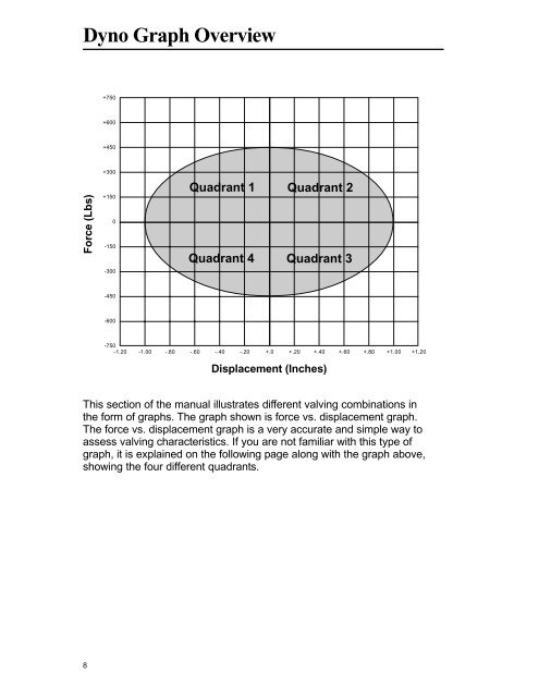
<strong>Dyno</strong> <strong>Graph</strong> <strong>Overview</strong><br />
Force (Lbs)<br />
8<br />
+750<br />
+600<br />
+450<br />
+300<br />
+150<br />
0<br />
-150<br />
-300<br />
-450<br />
-600<br />
Quadrant 1<br />
Quadrant 4<br />
Quadrant 2<br />
Quadrant 3<br />
-750<br />
-1.20 -1.00 -.80 -.60 -.40 -.20 +.0 +.20 +.40 +.60 +.80 +1.00 +1.20<br />
Displacement (Inches)<br />
This section of the manual illustrates different valving combinations in<br />
the form of graphs. The graph shown is force vs. displacement graph.<br />
The force vs. displacement graph is a very accurate and simple way to<br />
assess valving characteristics. If you are not familiar with this type of<br />
graph, it is explained on the following page along with the graph above,<br />
showing the four different quadrants.