Dyno Graph Overview - Penske Racing Shocks
Dyno Graph Overview - Penske Racing Shocks
Dyno Graph Overview - Penske Racing Shocks

Create successful ePaper yourself
Turn your PDF publications into a flip-book with our unique Google optimized e-Paper software.
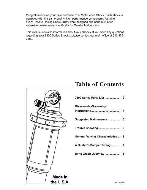
Congratulations on your new purchase of a 7800 Series Shock. Each shock is<br />
equipped with the same quality, high performance components found in<br />
every <strong>Penske</strong> <strong>Racing</strong> Shock. They were designed and hand built after<br />
extensive development specifically for Quarter Midget cars.<br />
This manual contains information about your shocks. If you have any questions<br />
regarding your 7800 Series <strong>Shocks</strong>, please contact our main office at 610-375-<br />
6180.<br />
Made in<br />
the U.S.A.<br />
Table of Contents<br />
7800 Series Parts List ................... 2<br />
Disassembly/Assembly<br />
Instructions .................................... 4<br />
Suggested Maintenance ............... 5<br />
Trouble Shooting ........................... 5<br />
General Valving Characteristics .. 6<br />
A Guide To Damper Tuning ........... 7<br />
<strong>Dyno</strong> <strong>Graph</strong> <strong>Overview</strong> ................... 8<br />
1<br />
REV: 8/10/06
7800 Series Parts List<br />
2<br />
3<br />
1<br />
2<br />
4<br />
5<br />
9<br />
10<br />
12<br />
13<br />
11<br />
6<br />
7<br />
8<br />
7<br />
8<br />
15<br />
18<br />
17<br />
21<br />
14<br />
16<br />
15<br />
19<br />
20<br />
26<br />
22<br />
23<br />
24<br />
25<br />
28<br />
27
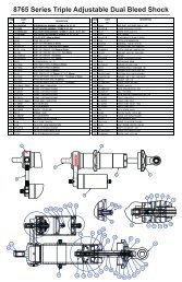
7800 Series Parts List<br />
ITEM NO. PART NO. DESCRIPTION<br />
1 SC-50 Screw, Ball Plunger<br />
2 RH-78175 Ride Height Adjuster, 7800, 1.75"<br />
3 IU-06 Valve Cap, High Temperature<br />
4 IU-04 Valve Core, 2000 psi<br />
5 IU-22-S Air Valve, Port O-Ring, S.S.<br />
6 OR-2010-B O-Ring, 2-010, Buna 70 Duro<br />
7 MO-5 Mono Ball, .312" ID X .375" W<br />
8 RR-75 Retaining Ring, .783" OD, VH-75<br />
9 BC-78 Body Cap, 7800<br />
10 OR-2117-B O-Ring, 2-117, Buna 70 Duro<br />
11 PI-78 Floating Piston, 7800 SERIES<br />
12 OR-2122-B O Ring, 2-122, Buna 70 Duro<br />
13 BD-78250 Body, 7800, 2 1/2" Stroke<br />
14 NT-375R Ring Nut, .375" X 16<br />
15 VW- Valve Shims<br />
16 PI-110025 Piston, 1°/1°, 0 Bld, 25mm<br />
17 PB-25 Piston Band, 25mm (1.00")<br />
18 VW-7800 Top Out Plate, 7800<br />
19 RR-37 Wire Ring, .043" Wire Dia. X .375" ID<br />
20 BU-06DU06 Bushing, DU .375" X .375"<br />
21 OR-2110-V O-Ring, 2-110, Viton 90 Duro<br />
22 OR-2206-B O-Ring, 2-206, Buna 70 Duro<br />
23 SB-78 Shaft Bearing, 7800<br />
24 SL-375 Shaft Wiper, 3/8" Shaft Bearing<br />
25 SH-78NA250 Shaft, 7800 Non-Adj., 2 1/2" Stroke<br />
26 SR-78175 Spring Retainer, 7800, 1.75"<br />
27 RR-46 Retaining Pin, 7800 Spring Retainer<br />
28 EY-78NA Eyelet, 7800, Non-Adjustable<br />
TOOLS AND ACCESSORIES<br />
KT-78SHIMS Shim Kit, 7800 Series<br />
TL-78SC 7800 Shaft Clamp<br />
TL-78W 7800 Bearing Wrench<br />
3
Disassembly / Assembly Instructions<br />
Disassembly Instructions<br />
1. Depressurize the shock.<br />
2. Clamp the body cap eyelet in the vise with the shaft eyelet pointing up.<br />
3. Unscrew the shaft bearing assembly from the shock body and remove the shaft<br />
assembly using a <strong>Penske</strong> bearing wrench (Part number TL-78W)<br />
4. Drain the oil, when needed. Please dispose of properly.<br />
5. Clamp the shaft eyelet in the vise with the piston pointing up.<br />
6. Remove the 1/2" ring nut to access valving.<br />
Assembly Instructions<br />
1. Install shaft bearing. Be sure to grease seals and o-rings to prevent any damage.<br />
2. Reinstall eyelet. Use Red Loctite on eyelet threads and tighten securely.<br />
3. Reassemble the shaft, be sure that the piston is properly positioned. With the<br />
shaft still in the vise, the compression valve stack is on the bottom of the piston<br />
and the rebound on the top. Bleed holes are on the rebound side (facing �)<br />
4. Torque 1/2" ring nut to 150 in•lbs.<br />
5. Pressurize body to 50 psi. Fill body with oil*, stopping at lower threads.<br />
*<strong>Penske</strong> Suspension Fluid (Silkolene Pro RSF 2.5 wt.) is recommended. Use of alternate<br />
fluids may have an adverse effect on the damper's internal sealing components.<br />
6. Insert shaft assembly with piston band into body. Move piston assembly up and down<br />
slowly (1"-2" strokes) to extract all air. DO NOT pull piston assembly out of the oil at<br />
this time.<br />
NOTE: this step is very important; take your time, repeat as needed. When all air<br />
is bled out, slide the shaft bearing down and screw it into the body until it is snug.<br />
Let the pressure out of the shock and finish tightening the bearing.<br />
(DO NOT OVER TIGHTEN).<br />
7. With the shaft fully extended, charge shock with desired pressure.<br />
(DO NOT EXCEED 150 PSI)<br />
Replacing the Shaft Bearing Seals / Eyelet<br />
1. Remove eyelet from shaft using a shaft clamp (Part number TL-78SC)<br />
2. ONLY REMOVE SHAFT BEARING OVER EYELET THREADS.<br />
3. Replace seals and wiper if needed.<br />
Continue following steps 1 through 7 in the Assembly instructions above.<br />
Specifications<br />
Ring nut, 150 in•lbs<br />
Eyelet to Shaft, (Red Loctite)<br />
4<br />
Shaft Eyelet<br />
Shaft Bearing<br />
Nitrogen Pressure Valve<br />
Body Cap Eyelet
Suggested Maintenance<br />
<strong>Shocks</strong> should be serviced yearly by <strong>Penske</strong> <strong>Racing</strong> <strong>Shocks</strong> or an<br />
authorized dealer.<br />
Trouble Shooting<br />
LOSS OF NITROGEN PRESSURE ............. Valve core (Part number<br />
IU-04) is not tight or needs<br />
to be replaced, o-ring (Part<br />
number OR-2010-B) on air<br />
valve needs to be replaced.<br />
OIL LEAK AROUND SHAFT ........................ Shaft seal o-ring (Part<br />
number OR-2110-V) or<br />
wiper (Part number SL-375)<br />
needs to be replaced.<br />
Note: minimal oil seepage<br />
is normal.<br />
OIL LEAK BETWEEN<br />
SHAFT BEARING AND BODY ..................... Shaft bearing o-ring (Part<br />
number OR-2206-B) needs<br />
to be replaced.<br />
5
General Valving Characteristics<br />
The damping characteristics of your shock are determined by the<br />
compression and rebound valve stacks located on the main piston.<br />
The valve stacks are made up of a series of high quality shims, which are<br />
made to flex under the force of oil flowing through the piston ports and<br />
then return to their original state.<br />
The thickness of the individual shims determines the amount of damping<br />
force the shock will produce. By changing the thickness of the individual<br />
shims, damping forces will be altered. For example, if you are running an<br />
“3” compression valving, where all the shims in the stack are .XXX thick<br />
and you replace them with a “4” compression valving, which consists of all<br />
.XXX thick shims, the compression damping will increase.<br />
* When the shaft is moving very slowly oil passes through the bleed<br />
hole(s), if there is one, before it passes to the shims.<br />
6<br />
High Speed Low Speed* High Speed<br />
Rebound Compression and Rebound Compression
A Guide To Damper Tuning<br />
The ultimate purpose of a shock is to work together with the spring to keep<br />
the tire on the track. In compression (bump) to help control the movement<br />
of the wheel and in rebound to help absorb the stored energy of the compressed<br />
spring.<br />
Usually in low grip situations, allowing more bleed or less low speed damping<br />
is desirable to delay tire loading upon initial roll.<br />
In dry high grip conditions, adding damping or restricting bleed will load the<br />
tire sooner upon initial roll increasing platform stability.<br />
A car with too much low speed damping will usually lack grip in change of<br />
directions, cannot put power down in slower corners (wheel spin) and lack<br />
overall grip after initial turn in.<br />
If traction is a problem coming off slow corners, reducing low speed damping<br />
or adding more bleed will help weight transfer at the rear thus increasing<br />
traction.<br />
Also, the amount of rebound can have a great influence on weight<br />
transfer. Less front rebound allows weight transfer to the rear under<br />
acceleration. Less rebound in the rear allows for a greater amount of<br />
weight transfer to the front under braking and turn in.<br />
When a shock is over damped in rebound, it can pack down in a series<br />
of bumps and a driver will recognize this as too stiff and usually will think<br />
it is compression damping. Too much rebound can cause lack of grip<br />
on cornering.<br />
7
<strong>Dyno</strong> <strong>Graph</strong> <strong>Overview</strong><br />
Force (Lbs)<br />
8<br />
+750<br />
+600<br />
+450<br />
+300<br />
+150<br />
0<br />
-150<br />
-300<br />
-450<br />
-600<br />
Quadrant 1<br />
Quadrant 4<br />
Quadrant 2<br />
Quadrant 3<br />
-750<br />
-1.20 -1.00 -.80 -.60 -.40 -.20 +.0 +.20 +.40 +.60 +.80 +1.00 +1.20<br />
Displacement (Inches)<br />
This section of the manual illustrates different valving combinations in<br />
the form of graphs. The graph shown is force vs. displacement graph.<br />
The force vs. displacement graph is a very accurate and simple way to<br />
assess valving characteristics. If you are not familiar with this type of<br />
graph, it is explained on the following page along with the graph above,<br />
showing the four different quadrants.
<strong>Dyno</strong> <strong>Graph</strong> <strong>Overview</strong><br />
REBOUND SHIMS<br />
CLOSE AND<br />
COMPRESSION SHIMS<br />
BEGIN TO REACT<br />
Low Speed<br />
Bleed Holes<br />
Through<br />
Piston<br />
QUADRANT #1<br />
This is the beginning of<br />
the compression stroke.<br />
Where the graph crosses<br />
the zero line (pounds) in<br />
quadrant #1 begins the<br />
compression stroke.<br />
Approximately the first<br />
1/2" of displacement is<br />
formed with relation to the<br />
low speed bleed holes.<br />
When the shaft reaches<br />
a certain velocity, the<br />
low speed bleed holes<br />
shut off and the compression<br />
valve stack begins<br />
to react.<br />
COMPRESSION SHIMS<br />
REACT<br />
QUADRANT #2<br />
This quadrant begins with<br />
the compression valve<br />
stack open. Where the<br />
graph crosses the zero<br />
line (inches) in quadrant<br />
#2 is the maximum force<br />
produced by the compression<br />
valving. As the<br />
shock approaches the full<br />
compression point, the<br />
compression valve stack<br />
begins to close as it approaches<br />
the rebound<br />
movement.<br />
�����<br />
Low Speed<br />
Bleed Holes<br />
Through<br />
Piston<br />
COMPRESSION SHIMS<br />
CLOSE AND<br />
REBOUND SHIMS<br />
BEGIN TO REACT<br />
QUADRANT #3<br />
This quadrant begins with<br />
the shock at full compression<br />
and the compression<br />
valve stack closed.<br />
Where the graph crosses<br />
the zero line (pounds) in<br />
quadrant #3 begins the<br />
rebound stroke. Approximately<br />
the first 1/2" of<br />
displacement is formed<br />
with relation to the rebound<br />
bleed through the<br />
piston. When the shaft<br />
reaches a certain velocity,<br />
the bleed shuts off and<br />
the rebound valve stack<br />
begins to react.<br />
REBOUND SHIMS<br />
REACT<br />
QUADRANT #4<br />
This quadrant begins<br />
with the rebound valve<br />
stack open. Where the<br />
graph crosses the zero<br />
line (inches) in quadrant<br />
# 4<br />
is the maximum force<br />
produced by the rebound<br />
valving. As the shock<br />
approaches the full extension<br />
point, the rebound<br />
valve stack begins<br />
to close as it approaches<br />
the compression movement.<br />
At this point the<br />
cycle starts over again in<br />
quadrant #1.<br />
An easy way to help picture what is going on here is to relate the graph’s shape to<br />
what the dyno is doing to the shock. The dyno uses a scotch yoke system (shown<br />
above), where the motor turns a crank and the sliding yoke allows the main dyno<br />
shaft to make the up and down movement at the preset stroke. The dyno software<br />
takes thousands of measurements throughout a single revolution of the crank. The<br />
sampled points are connected to form the graph. By relating the crank’s position to<br />
the corresponding graph quadrant and the circular crank movement may help in<br />
reading the graphs.<br />
�����<br />
9
<strong>Dyno</strong> <strong>Graph</strong> <strong>Overview</strong><br />
<strong>Penske</strong> <strong>Racing</strong> <strong>Shocks</strong> uses SPA or Roehrig Dynamometers because of their versatility and<br />
low speed metering and sample rates. <strong>Penske</strong> <strong>Shocks</strong> primarily uses the Force Average<br />
display, but SPA and Roehrig both offer Decelerating CD/Accelerating RD and Accelerating<br />
CD/Decelerating RD viewing options for all their graph displays.<br />
Force / Velocity Average<br />
This graph shows the averages of the<br />
accelerating and decelerating compression and<br />
rebound forces. It is a good quick, general<br />
review of the shock curve, but is the least<br />
accurate of the options displayed.<br />
Force / Velocity<br />
This graph displays the accelerating and decelerating<br />
compression and rebound forces. Think<br />
of this graph as the Force / Displacement graph<br />
(below) folded in half.<br />
* Hysteresis is the gap between accelerating and<br />
decelerating compression and rebound damping.<br />
It is affected by the type of piston and the<br />
shims used. The bleed hole(s) will close the gap<br />
or soften the low speed forces.<br />
OVAL (Force / Displacement)<br />
QUADRANT #1<br />
This is the beginning of the compression stroke. Where<br />
the graph crosses the zero line (pounds) in quadrant #1<br />
begins the compression stroke. Approximately the first 1/<br />
2" of displacement is formed with relation to the low<br />
speed bleed bypass. When the shaft reaches a certain<br />
velocity, the low speed bleed holes choke off and the<br />
compression valve stack begins to react.<br />
QUADRANT #2<br />
This quadrant begins with the compression valve stack<br />
open. Where the graph crosses the zero line (inches) in<br />
quadrant #2 is the maximum force produced by the<br />
compression valving. As the shock approaches the full<br />
compression point, the compression valve stack begins<br />
to close as it approaches the rebound movement.<br />
QUADRANT #3<br />
This quadrant begins with the shock at full compression<br />
and the compression valve stack closed. Where the<br />
graph crosses the zero line (pounds) in quadrant #3<br />
begins the rebound stroke. Approximately the first 1/2" of<br />
displacement is formed with relation to the rebound<br />
bleed through the piston. When the shaft reaches a<br />
certain velocity, the bleed chokes off and the rebound<br />
valve stack begins to react.<br />
QUADRANT #4<br />
This quadrant begins with the rebound valve stack open.<br />
Where the graph crosses the zero line (inches) in<br />
quadrant #4 is the maximum force produced by the<br />
rebound valving. As the shock approaches the full<br />
extension point, the rebound valve stack begins to close<br />
as it approaches the compression movement. At this<br />
point the cycle starts over again in quadrant #1.<br />
10<br />
2<br />
1<br />
3<br />
4<br />
��<br />
1 2<br />
4 3<br />
Hysteresis
<strong>Dyno</strong> <strong>Graph</strong> <strong>Overview</strong><br />
Damping Forces (Lbs)<br />
500<br />
400<br />
300<br />
200<br />
100<br />
0<br />
-100<br />
-200<br />
-300<br />
-400<br />
-500<br />
Low Speed Bleed Holes<br />
Bleed Chokes Off / Shims Activate (knee)<br />
Low Shaft Speed (slope)<br />
Compression<br />
0.00 1.00 2.00 3.00 4.00 5.00 6.00 7.00 8.00 9.00 10.00<br />
Shaft Velocity (In/Sec)<br />
Rebound<br />
Note:<br />
Remember that low speed damping characteristics are controlled by bleed through<br />
the bleed hole(s) in the piston, not the valve stacks.<br />
11
Notes<br />
12