Vitocal 300-G Technical Guide1.4 MB - Viessmann
Vitocal 300-G Technical Guide1.4 MB - Viessmann
Vitocal 300-G Technical Guide1.4 MB - Viessmann

You also want an ePaper? Increase the reach of your titles
YUMPU automatically turns print PDFs into web optimized ePapers that Google loves.
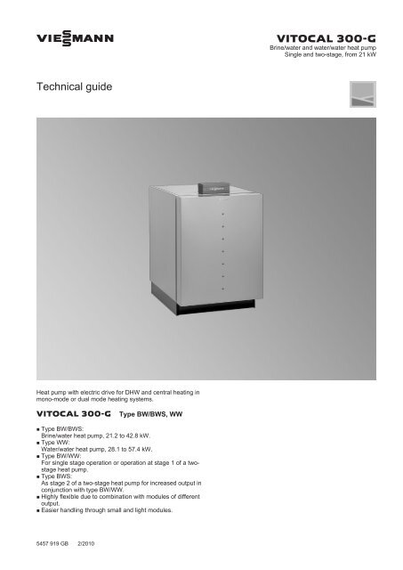
VIESMANN VITOCAL <strong>300</strong>-G<br />
Brine/water and water/water heat pump<br />
Single and two-stage, from 21 kW<br />
<strong>Technical</strong> guide<br />
Heat pump with electric drive for DHW and central heating in<br />
mono-mode or dual mode heating systems.<br />
VITOCAL <strong>300</strong>-G Type BW/BWS, WW<br />
■ Type BW/BWS:<br />
Brine/water heat pump, 21.2 to 42.8 kW.<br />
■ Type WW:<br />
Water/water heat pump, 28.1 to 57.4 kW.<br />
■ Type BW/WW:<br />
For single stage operation or operation at stage 1 of a twostage<br />
heat pump.<br />
■ Type BWS:<br />
As stage 2 of a two-stage heat pump for increased output in<br />
conjunction with type BW/WW.<br />
■ Highly flexible due to combination with modules of different<br />
output.<br />
■ Easier handling through small and light modules.<br />
5457 919 GB 2/2010
Index<br />
Index<br />
1. <strong>Vitocal</strong> <strong>300</strong>-G 1. 1 Product description ..................................................................................................... 4<br />
■ Benefits of type BW/BWS, WW .............................................................................. 4<br />
■ Delivered condition ................................................................................................. 4<br />
1. 2 Specification ............................................................................................................... 5<br />
■ Specification ............................................................................................................ 5<br />
■ Dimensions of type BW/BWS, WW ......................................................................... 7<br />
■ Output diagrams ..................................................................................................... 8<br />
2. Installation accessories 2. 1 Primary circuit ............................................................................................................. 11<br />
■ Sensor well set, primary circuit ............................................................................... 11<br />
■ Brine circuit pressure switch ................................................................................... 11<br />
■ Brine accessory pack .............................................................................................. 11<br />
■ Primary pump .......................................................................................................... 12<br />
■ Brine distributor for geothermal collectors .............................................................. 13<br />
■ Brine distributor for geothermal probes/geothermal collectors ............................... 14<br />
■ Heat transfer medium Tyfocor ................................................................................ 16<br />
■ Filling station ........................................................................................................... 16<br />
2. 2 Secondary circuit ........................................................................................................ 17<br />
■ Secondary pump ..................................................................................................... 17<br />
■ Safety equipment block ........................................................................................... 18<br />
2. 3 Cooling ........................................................................................................................ 19<br />
■ Contact humidistat .................................................................................................. 19<br />
■ Natural cooling extension kit ................................................................................... 19<br />
■ 2-way motorised ball valve (DN 32) ........................................................................ 19<br />
■ Three-way diverter valve (R 1¼) ............................................................................. 19<br />
■ Room temperature sensor ...................................................................................... 19<br />
■ Frost stat ................................................................................................................. 19<br />
■ Fan convectors Vitoclima 200-C ............................................................................. 19<br />
2. 4 DHW heating via an external heat exchanger ............................................................ 22<br />
■ 2-way motorised ball valve (DN 32) ........................................................................ 22<br />
■ Cylinder primary pump ............................................................................................ 22<br />
3. Design information 3. 1 Power supply and tariffs ............................................................................................. 22<br />
■ Application procedure ............................................................................................. 22<br />
3. 2 Positioning requirements ............................................................................................ 22<br />
■ Minimum clearances ............................................................................................... 23<br />
■ Min. space requirement .......................................................................................... 23<br />
■ Electrical connections ............................................................................................. 23<br />
3. 3 Hydraulic connections ................................................................................................. 26<br />
■ Connections on the primary side brine/water (stages 1 and 2) ............................... 26<br />
■ Connections on the primary side water/water (stages 1 and 2) .............................. 28<br />
■ Connections on secondary side for two-stage heat pumps .................................... 31<br />
3. 4 System versions ......................................................................................................... 33<br />
3. 5 Sizing the heat pump .................................................................................................. 34<br />
■ Mono-mode operation ............................................................................................. 34<br />
■ Mono-energetic operation ....................................................................................... 35<br />
■ Dual mode operation ............................................................................................... 35<br />
■ Supplement for DHW heating ................................................................................. 35<br />
■ Supplement for setback mode ................................................................................ 36<br />
3. 6 Heat source for brine/water heat pumps ..................................................................... 36<br />
■ Frost protection ....................................................................................................... 36<br />
■ Geothermal collector ............................................................................................... 36<br />
■ Geothermal probe ................................................................................................... 39<br />
■ Expansion vessel for primary circuit ....................................................................... 40<br />
■ Pipework, primary circuit ......................................................................................... 41<br />
■ Pump output supplements (percentage) for operation with Tyfocor ....................... 43<br />
3. 7 Heat source for water/water heat pumps .................................................................... 43<br />
■ Groundwater ........................................................................................................... 43<br />
■ Calculating the required groundwater volume ........................................................ 44<br />
■ Permits for a groundwater/water heat pump system .............................................. 44<br />
■ Sizing the heat exchanger, primary circuit/separating heat exchanger .................. 45<br />
■ Cooling water .......................................................................................................... 45<br />
3. 8 Central heating/central cooling ................................................................................... 46<br />
■ Heating circuit ......................................................................................................... 46<br />
■ Heating circuit and heat distribution ........................................................................ 46<br />
■ Cooling operation .................................................................................................... 47<br />
2 VIESMANN VITOCAL <strong>300</strong>-G<br />
5457 919 GB
Index (cont.)<br />
3. 9 Systems with heating water buffer cylinder ................................................................ 47<br />
■ Heating water buffer cylinder operated in parallel ................................................... 47<br />
■ Heating water buffer cylinder for optimised runtimes .............................................. 48<br />
■ Heating water buffer cylinder for bridging periods when the supply is blocked ...... 48<br />
3.10 Water quality ............................................................................................................... 48<br />
■ Heating water .......................................................................................................... 48<br />
3.11 DHW heating .............................................................................................................. 49<br />
■ DHW connection ..................................................................................................... 49<br />
■ Function description regarding DHW heating ......................................................... 49<br />
■ Hydraulic connection, primary store system ........................................................... 50<br />
3.12 Cooling operation ........................................................................................................ 53<br />
■ Types and configuration .......................................................................................... 53<br />
■ Cooling function Natural cooling ............................................................................. 53<br />
■ Hydraulic connection, natural cooling function ........................................................ 53<br />
3.13 Swimming pool water heating ..................................................................................... 56<br />
■ Hydraulic connection, swimming pool ..................................................................... 56<br />
■ Sizing the plate heat exchanger .............................................................................. 57<br />
3.14 Connection of solar thermal systems .......................................................................... 57<br />
■ Sizing the solar expansion vessel ........................................................................... 58<br />
4. Heat pump control unit 4. 1 Vitotronic 200, type WO1A ......................................................................................... 59<br />
■ Structure and functions ........................................................................................... 59<br />
■ Time switch ............................................................................................................. 59<br />
■ Setting the operating programs ............................................................................... 60<br />
■ Frost protection function ......................................................................................... 60<br />
■ Heating and cooling curve settings (slope and level) .............................................. 60<br />
■ Heating systems with heating water buffer cylinder or low loss header .................. 61<br />
■ Outside temperature sensor ................................................................................... 61<br />
■ Specification Vitotronic 200, type WO1A ................................................................ 61<br />
4. 2 Control unit accessories ............................................................................................. 62<br />
■ Contactor relay ........................................................................................................ 62<br />
■ Contact temperature sensor as system flow temperature sensor ........................... 63<br />
■ Cylinder temperature sensor ................................................................................... 63<br />
■ Thermostat for controlling the swimming pool temperature .................................... 63<br />
■ Contact temperature sensor ................................................................................... 63<br />
■ Mixer motor ............................................................................................................. 64<br />
■ Extension kit for one heating circuit with mixer with integral mixer motor ............... 64<br />
■ Extension kit for one heating circuit with mixer for separate mixer motor ............... 65<br />
■ Immersion thermostat ............................................................................................. 65<br />
■ Contact thermostat .................................................................................................. 65<br />
■ Vitotrol 200A ........................................................................................................... 66<br />
■ Room temperature sensor for separate cooling circuit ........................................... 66<br />
■ KM BUS distributor ................................................................................................. 67<br />
■ External extension H1 ............................................................................................. 67<br />
■ Vitocom 100, type GSM .......................................................................................... 67<br />
■ Vitocom <strong>300</strong>, type FA5, FI2, GP2 ........................................................................... 68<br />
■ LON communication module ................................................................................... 69<br />
■ LON connecting cable for data exchange between control units ............................ 70<br />
■ Extension of the connecting cable .......................................................................... 70<br />
■ Terminator ............................................................................................................... 70<br />
5. Keyword index .............................................................................................................................................. 71<br />
5457 919 GB<br />
VITOCAL <strong>300</strong>-G VIESMANN 3
1<br />
<strong>Vitocal</strong> <strong>300</strong>-G<br />
1.1 Product description<br />
Heat pumps with electric drive for DHW and central heating in monomode,<br />
mono-energetic or dual mode operation.<br />
The brine/water heat pumps extract heat from the ground with the help<br />
of geothermal collectors or probes.<br />
The ground provides almost completely stable temperatures all the<br />
year round, enabling the heat pumps to operate virtually independently<br />
of the outside temperature. They can cover the entire heat demand of<br />
a building, even on colder days.<br />
Benefits of type BW/BWS, WW<br />
The water/water heat pumps with delivery and return wells gain heat<br />
from the groundwater which offers stable temperatures, enabling the<br />
heat pumps to achieve constantly high COPs.<br />
Consequently they are suitable for year round heating operation and<br />
DHW provision.<br />
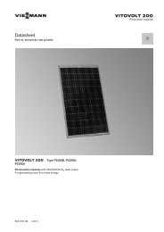
A Hermetically sealed Compliant scroll compressor<br />
B Condenser<br />
C Evaporator<br />
D Only type BW/WW:<br />
Weather-compensated, digital heat pump control unit<br />
Vitotronic 200, type WO1A<br />
■ Mono-mode for central and DHW heating.<br />
■ Menu-guided heat pump control unit Vitotronic 200, type WO1A, for<br />
weather-compensated heating mode.<br />
■ Max. flow temperature of 60 °C for high DHW convenience and ideal<br />
for modernising an existing radiator heating system.<br />
■ High COP to EN 14511: up to 4.8 (brine 0 °C/water 35 °C).<br />
■ Low operating costs with the highest efficiency at every operating<br />
point through the innovative RCD (Refrigerant Cycle Diagnostic)<br />
system with electronic expansion valve.<br />
■ Especially suitable for low heating system temperatures, e.g. underfloor<br />
heating.<br />
■ Highly flexible due to combination with modules of different output.<br />
■ Low noise and vibration emissions through 3-D sound concept<br />
■ Convenient for applying for subsidies: with integral energy statement.<br />
■ Easier handling through small and light modules.<br />
■ Higher output can be achieved through cascade arrangement:<br />
21.2 to 342.4 kW<br />
■ Type BWS:<br />
As stage 2 of a two-stage heat pump for increased output in conjunction<br />
with type BW and WW.<br />
Delivered condition<br />
Type BW<br />
■ Compact heat pump design (with soft starter).<br />
■ Epoxy-coated casing.<br />
■ CFC-free, non-combustible refrigerant R 410A (refrigerant mixture,<br />
comprising 50 % R 32 and 50 % R 125).<br />
■ Evaporator and condenser made from copper-soldered stainless<br />
steel plate heat exchanger (1.4401), for the heating circuit and brine/<br />
groundwater circuit.<br />
■ Electronic expansion valve and patented refrigerant distribution.<br />
■ New refrigerant RCD (Refrigerant Cycle Diagnostic) circuit diagnostic<br />
system.<br />
■ Outside temperature sensor, flow and return temperature sensors<br />
plus sensors for the primary circuit flow and return.<br />
■ With fitted weather-compensated digital heat pump control unit<br />
Vitotronic 200, type WO1A<br />
Type WW<br />
■ Heat pump type BW<br />
■ Water/water heat pump conversion kit (frost stat for primary circuit<br />
and flow limiter for well circuit)<br />
Type BWS<br />
■ Heat pump type BW without heat pump control unit<br />
5457 919 GB<br />
4 VIESMANN VITOCAL <strong>300</strong>-G
<strong>Vitocal</strong> <strong>300</strong>-G (cont.)<br />
1.2 Specification<br />
Specification<br />
Type BW/BWS<br />
BW/BWS 121 129 145<br />
Output data to DIN EN 14511 (0/35 °C, 5 K spread)<br />
Rated heating output kW 21.2 28.8 42.8<br />
Refrigerating capacity kW 17.0 23.3 34.2<br />
Power consumption kW 4.48 5.96 9.28<br />
Coefficient of performance ∊ (COP) 4.73 4.83 4.6<br />
Output data to DIN EN 255 (0/35 °C, 10 K spread)<br />
Rated heating output kW 21.5 29.2 43.5<br />
Refrigerating capacity kW 17.5 23.8 35.0<br />
Power consumption kW 4.33 5.75 9.16<br />
Coefficient of performance ∊ (COP) 4.97 5.08 4.8<br />
Brine (primary circuit)<br />
Content l 7.3 9.1 12.7<br />
Min. flow rate (Δt = 5 K) l/h 3<strong>300</strong> 4200 6500<br />
Pressure drop mbar 90 120 200<br />
Max. flow temperature °C 25 25 25<br />
Min. flow temperature °C –5 –5 –5<br />
Heating water (secondary circuit)<br />
Content l 7.3 9.1 12.7<br />
Min. flow rate (Δt = 10 K) l/h 1900 2550 3700<br />
Pressure drop mbar 30 48 60<br />
Max. flow temperature °C 60 60 60<br />
1<br />
5457 919 GB<br />
Type WW<br />
WW 121 129 145<br />
Output data to DIN EN 14511 (10/35 °C, 5 K spread)<br />
Rated heating output kW 28.1 37.1 58.9<br />
Refrigerating capacity kW 23.7 31.4 48.9<br />
Power consumption kW 4.73 6.2 10.7<br />
Coefficient of performance ∊ (COP) 5.94 6.0 5.5<br />
Brine (primary circuit)<br />
Content l 7.3 9.1 12.7<br />
Min. flow rate (Δt = 4 K) l/h 5200 7200 10600<br />
Pressure drop mbar 200 <strong>300</strong> 440<br />
Max. inlet temperature °C 25 25 25<br />
Min. inlet temperature °C -5 -5 -5<br />
Heating water (secondary circuit)<br />
Content l 7.3 9.1 12.7<br />
Min. flow rate (Δt = 10 K) l/h 1900 2550 3700<br />
Pressure drop mbar 30 48 60<br />
Max. flow temperature °C 60 60 60<br />
Type BW/BWS, WW<br />
BW/BWS, WW 121 129 145<br />
Rated voltage, heat pump compressor stage 2 (type BWS) V 3/PE 400 V/50 Hz<br />
Rated current, compressor A 16 22 34<br />
Starting current, compressor (with starting current limiter) A
<strong>Vitocal</strong> <strong>300</strong>-G (cont.)<br />
1<br />
BW/BWS, WW 121 129 145<br />
Refrigerant circuit<br />
Refrigerant R 410 A<br />
Fill volume kg 6.5 7.3 10.0<br />
Compressor Type Hermetically sealed scroll compressor<br />
Permiss. operating pressure, high pressure side bar 43 43 43<br />
Permiss. operating pressure, low pressure side bar 28 28 28<br />
Permiss. operating pressure<br />
Primary circuit bar 3 3 3<br />
Secondary circuit bar 3 3 3<br />
Dimensions<br />
Total length mm 1085 1085 1085<br />
Total width mm 780 780 780<br />
Total height (with open control unit) mm 1267 1267 1267<br />
Connections<br />
Primary flow and return G 2 2 2<br />
Heating flow and return G 2 2 2<br />
Weight<br />
Heat pump stage 1 (type BW/WW) kg 282 305 345<br />
Heat pump stage 2 (type BWS) kg 277 <strong>300</strong> 340<br />
Sound power level at 0/35 °C<br />
(test with reference to DIN EN ISO 9614-2)<br />
dB(A) 42 44 44<br />
5457 919 GB<br />
6 VIESMANN VITOCAL <strong>300</strong>-G
<strong>Vitocal</strong> <strong>300</strong>-G (cont.)<br />
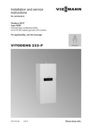
Dimensions of type BW/BWS, WW<br />
1<br />
1074<br />
88<br />
171<br />
301<br />
86<br />
< 42 V<br />
230 V<br />
400 V<br />
< 42 V<br />
230 V<br />
400 V<br />
86<br />
88<br />
171<br />
301<br />
60<br />
1074 87<br />
1267<br />
540<br />
270<br />
230<br />
540<br />
270<br />
230<br />
1025<br />
1025 60<br />
= <strong>300</strong><br />
780 780<br />
Type BWS on the left; type BW/WW on the right<br />
5457 919 GB<br />
VITOCAL <strong>300</strong>-G VIESMANN 7
<strong>Vitocal</strong> <strong>300</strong>-G (cont.)<br />
Output diagrams<br />
1<br />
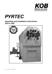
Type 121<br />
35<br />
30<br />
25<br />
20<br />
D<br />
E<br />
F<br />
G<br />
D<br />
E<br />
F<br />
G<br />
A Heating output<br />
B Refrigerating capacity<br />
C Power consumption<br />
D T HV = 35 °C<br />
E T HV = 45 °C<br />
F T HV = 55 °C<br />
G T HV = 60 °C<br />
T HV Heating circuit flow temperature<br />
Note<br />
Data for the COP was calculated with reference to DIN EN 14511.<br />
A<br />
15<br />
Output in kW<br />
Ɛ Coefficient of performance (COP)<br />
B<br />
10<br />
C<br />
5<br />
0<br />
-5 0 5<br />
Water or brine temperature in °C<br />
8<br />
7<br />
6<br />
5<br />
4<br />
3<br />
2<br />
1<br />
0<br />
-5 0 5<br />
Water or brine temperature in °C<br />
10<br />
10<br />
G<br />
F<br />
E<br />
D<br />
15<br />
D<br />
E<br />
F<br />
G<br />
15<br />
5457 919 GB<br />
8 VIESMANN VITOCAL <strong>300</strong>-G
<strong>Vitocal</strong> <strong>300</strong>-G (cont.)<br />
Type 129<br />
45<br />
40<br />
35<br />
30<br />
D<br />
E<br />
F<br />
G<br />
D<br />
E<br />
F<br />
A Heating output<br />
B Refrigerating capacity<br />
C Power consumption<br />
D T HV = 35 °C<br />
E T HV = 45 °C<br />
F T HV = 55 °C<br />
G T HV = 60 °C<br />
T HV Heating circuit flow temperature<br />
Note<br />
Data for the COP was calculated with reference to DIN EN 14511.<br />
1<br />
G<br />
25<br />
A<br />
20<br />
B<br />
15<br />
Output in kW<br />
Ɛ Coefficient of performance (COP)<br />
10<br />
C<br />
5<br />
0<br />
-5 0 5<br />
Water or brine temperature in °C<br />
8<br />
7<br />
6<br />
5<br />
4<br />
3<br />
2<br />
1<br />
0<br />
-5 0 5<br />
Water or brine temperature in °C<br />
10<br />
10<br />
G<br />
F<br />
E<br />
D<br />
15<br />
D<br />
E<br />
F<br />
G<br />
15<br />
5457 919 GB<br />
VITOCAL <strong>300</strong>-G VIESMANN 9
<strong>Vitocal</strong> <strong>300</strong>-G (cont.)<br />
Type 145<br />
1<br />
70<br />
60<br />
50<br />
40<br />
D<br />
E<br />
F<br />
G<br />
D<br />
E<br />
F<br />
G<br />
A Heating output<br />
B Refrigerating capacity<br />
C Power consumption<br />
D T HV = 35 °C<br />
E T HV = 45 °C<br />
F T HV = 55 °C<br />
G T HV = 60 °C<br />
T HV Heating circuit flow temperature<br />
Note<br />
Data for the COP was calculated with reference to DIN EN 14511.<br />
A<br />
30<br />
Output in kW<br />
Coefficient of performance ε (COP)<br />
B<br />
20<br />
C<br />
10<br />
0<br />
-5 0 5<br />
Water or brine temperature in °C<br />
7<br />
6<br />
5<br />
4<br />
3<br />
2<br />
1<br />
0<br />
-5 0 5<br />
Water or brine temperature in °C<br />
10<br />
10<br />
G<br />
F<br />
E<br />
D<br />
15<br />
D<br />
E<br />
F<br />
G<br />
15<br />
5457 919 GB<br />
10 VIESMANN VITOCAL <strong>300</strong>-G
Installation accessories<br />
2.1 Primary circuit<br />
Sensor well set, primary circuit<br />
Part no. 7460 714<br />
For on-site primary circuit pipework.<br />
Brine circuit pressure switch<br />
Part no. 9532 663<br />
Note<br />
Cannot be used in conjunction with potassium carbonate-based heat<br />
transfer medium.<br />
Components:<br />
■ Pipe with connection R1¼ (2 pce)<br />
■ Sensor well for temperature sensors (flow and return)<br />
Note<br />
The temperature sensors are included in the standard delivery of the<br />
heat pump.<br />
2<br />
5457 919 GB<br />
Brine accessory pack<br />
Only for single stage heat pump type BW 121 and BW 129.<br />
■ For systems with a brine circuit pump (primary pump) in the brine<br />
return.<br />
■ Suitable for <strong>Viessmann</strong> heat transfer medium "Tyfocor" based on<br />
ethylene glycol (see chapter "Heat transfer medium").<br />
■ Brine accessory pack for single and two-stage heat pumps, thermally<br />
insulated with vapour diffusion-proof material.<br />
Components:<br />
■ Air separator<br />
■ Safety valve (3 bar)<br />
■ Pressure gauge<br />
■ Drain & fill valves (2 pce)<br />
■ Fittings for installing the primary pump<br />
■ Shut-off valves<br />
■ Wall mounting bracket<br />
■ Thermal insulation (vapour diffusion-proof)<br />
■ Expansion vessel<br />
■ Subject to part no., with or without circulation pump<br />
Heat pump type BW 121 BW 129 BW 145<br />
Expansion vessel 35 l 50 l on-site<br />
Part no. for brine accessory<br />
pack<br />
Without circulation pump Z008 585 Z008 586 on-site<br />
(Connection set for on-site<br />
circulation pump G 2)<br />
With Wilo high efficiency Z008 594 —<br />
circulation pump, type<br />
Stratos Para (3 - 11 m),<br />
230 V~<br />
(Connection set for on-site<br />
circulation pump G 1½)<br />
With Wilo standard circulation<br />
pump:<br />
– Type TOP S 30/7, Z008 591 —<br />
400 V~<br />
(Connection set for onsite<br />
circulation pump<br />
G 2)<br />
– Type TOP S 30/10,<br />
400 V~<br />
(Connection set for onsite<br />
circulation pump<br />
G 2)<br />
— Z008 592<br />
Circulation pump curves<br />
See chapter "Primary pump".<br />
VITOCAL <strong>300</strong>-G VIESMANN 11
Installation accessories (cont.)<br />
670<br />
86<br />
E<br />
D<br />
2<br />
F<br />
G 1¼ G 1¼<br />
H<br />
360<br />
C<br />
G<br />
B<br />
B<br />
G 1¼<br />
N<br />
B<br />
A<br />
192<br />
G 1¼<br />
192<br />
K<br />
M<br />
L<br />
C<br />
A Primary circuit flow (heat pump brine inlet)<br />
B Ball valve<br />
C Drain & fill valve<br />
D Pressure switch connection<br />
E Air separator<br />
F Primary circuit flow (brine inlet, brine accessory pack)<br />
G Pressure gauge<br />
H Safety valve (3 bar)<br />
K Primary circuit return (brine outlet, brine accessory pack)<br />
L Expansion vessel connection<br />
M Primary circuit return (heat pump brine outlet)<br />
N Primary pump<br />
Assembly and installation information<br />
■ Fit the brine accessory pack horizontally to ensure the correct function<br />
of the air separator.<br />
■ Fit the air blow-off connector above the brine accessory pack.<br />
■ Check the circulation pump for an adequate residual head (see<br />
curves).<br />
Position the pump cable entry so that it points downwards or to the<br />
l.h. or r.h. side, or turn the pump head if required.<br />
■ If the brine circuit pressure switch is not connected, the brine accessory<br />
pack can also be installed in the external interconnecting duct<br />
(waterproof).<br />
Primary pump<br />
For installation in the primary circuit return (brine return)<br />
Components:<br />
■ Circulation pump 400 V~<br />
■ Thermal insulation (vapour diffusion-proof)<br />
■ Contactor relay<br />
Note<br />
For operation with water/Tyfocor, the pump output supplements<br />
should be taken into account (see page 43).<br />
Heat pump type BW 121 BW 129 BW 145<br />
Circulation pump part no.<br />
Wilo standard circulation<br />
Z007 441 — on-site<br />
pump,<br />
type TOP S 30/7,<br />
400 V~<br />
Wilo standard circulation<br />
pump,<br />
type TOP S 30/10,<br />
400 V~<br />
— Z007 442<br />
5457 919 GB<br />
12 VIESMANN VITOCAL <strong>300</strong>-G
Installation accessories (cont.)<br />
Wilo standard circulation pump curves<br />
Wilo high efficiency circulation pump curves<br />
Only in conjuction with brine accessory pack.<br />
8<br />
7<br />
6<br />
5<br />
4<br />
3<br />
min. (3 )<br />
(2 )<br />
max. (1 )<br />
Head<br />
in m<br />
12<br />
10<br />
8<br />
6<br />
4<br />
2<br />
0<br />
0 1 2 3 4 5<br />
Pump rate in m³/h<br />
2<br />
Head in m<br />
2<br />
1<br />
0<br />
0 1 2 3 4 5 6 7 8<br />
Pump rate in m³/h<br />
Type TOP S 30/7, 400 V~<br />
12<br />
11<br />
10<br />
9<br />
8<br />
7<br />
6<br />
Head in m<br />
5<br />
4<br />
min. (3 )<br />
(2 )<br />
max. (1 )<br />
3<br />
2<br />
1<br />
0<br />
0 1 2 3 4 5 6 7 8 9 10 11 12<br />
Pump rate in m³/h<br />
Output in W<br />
160<br />
140<br />
max.<br />
120<br />
10 m<br />
8 m<br />
100<br />
6 m<br />
80<br />
4 m<br />
60<br />
40<br />
2 m<br />
20<br />
0<br />
0 1 2 3 4 5<br />
Pump rate in m³/h<br />
Type Stratos Para (3 - 11 m), 230 V~<br />
Type TOP S 30/10, 400 V~<br />
Brine distributor for geothermal collectors<br />
(<strong>Vitocal</strong> rated heating output: max. 37.1 kW)<br />
Part no. 7143 762<br />
Brass brine distributor, pre-assembled on two anti-vibration mounts.<br />
Can be fitted to the house wall, in the cellar duct or in the central service<br />
duct.<br />
■ 2 quick-acting air vent valves<br />
■ 1 drain & fill valve per header<br />
Up to 4 brine distributors can be connected to each flow and return.<br />
Components:<br />
■ 2 headers for flow and return<br />
■ Flow and return connections for 10 brine circuits, ball valves and<br />
locking ring fittings (PE 20 × 2.0)<br />
5457 919 GB<br />
VITOCAL <strong>300</strong>-G VIESMANN 13
Installation accessories (cont.)<br />
670<br />
545<br />
33<br />
52<br />
1¼"<br />
55<br />
200<br />
2<br />
1¼"<br />
63<br />
A Header G 1¼ (flow)<br />
B Header G 1¼ (return)<br />
C Locking ring fittings for PE 20 × 2.0 mm<br />
D Ball valve for filling and draining<br />
E Ball valves for shutting off the individual circuits<br />
F Sound-absorbing panel<br />
Connection versions<br />
VL<br />
1 2 3 4 5 6 7 8 910<br />
RL<br />
10 9 8 7 6 5 4 3 2 1<br />
1 2 3 4 5 6 7 8 9 10<br />
11 12 13 14 15 16 17 18 19 20<br />
RL Brine return<br />
VL Brine flow<br />
10 9 8 7 6 5 4 3 2 1<br />
20 19 18 17 16 15 14 13 12 11<br />
Note<br />
For the allocation of brine distributor to heat pump type, see table in<br />
design information, "Heat sources for brine/water heat pumps",<br />
page 37.<br />
A Brine flow<br />
B Brine return<br />
Brine distributor for geothermal probes/geothermal collectors<br />
Locking ring fittings<br />
Number of brine circuits Part no.<br />
Geothermal<br />
probes<br />
Geothermal<br />
collectors<br />
PE 25 x 2.3 — 2 7373 332<br />
— 3 7373 331<br />
— 4 7182 043<br />
PE 32 x 2.9 2 2 7373 330<br />
3 3 7373 329<br />
4 4 7143 763<br />
Brine distributor for geothermal probes/geothermal collectors<br />
Nickel-plated brine distributor. Can be fitted to the house wall, in the<br />
cellar duct or in the central service duct.<br />
Components:<br />
■ Header for separate flow and return<br />
■ Flow and return connections for 2, 3 or 4 brine circuits, ball valves<br />
and locking ring fittings (PE 25 × 2.3 or PE 32 × 2.9)<br />
■ Installation accessories<br />
■ 2 drain & fill valves<br />
Up to 4 brine distributors can be connected to each flow and return.<br />
Brine distributors for 2, 3 and 4 brine circuits can be combined in any<br />
order.<br />
5457 919 GB<br />
14 VIESMANN VITOCAL <strong>300</strong>-G
Installation accessories (cont.)<br />
175<br />
335<br />
A<br />
C<br />
B<br />
E<br />
≈ 80<br />
F<br />
≈ 130<br />
2<br />
80<br />
D<br />
80<br />
Brine distributor for 2 brine circuits<br />
Brine distributor for 4 brine circuits<br />
A<br />
B<br />
255<br />
C<br />
A Union nut G 2 for ball valve connection, locking ring fitting or a<br />
further module<br />
B Ball valve for filling and draining<br />
C Header G 1½<br />
D Locking ring fittings for PE 32 × 2.9 mm or PE 25 × 2.3 mm<br />
E 2" end cap with G ½ plug<br />
F Ball valves for shutting off the individual circuits<br />
E<br />
≈ 130<br />
F<br />
80<br />
D<br />
Brine distributor for 3 brine circuits<br />
Connection versions<br />
1 2 3<br />
4<br />
VL<br />
VL<br />
4 3 2<br />
1<br />
RL<br />
1 2 3<br />
4<br />
5 6 7<br />
8<br />
Example for 4 brine circuits<br />
4 3 2<br />
1<br />
8 7 6<br />
RL<br />
5<br />
RL Brine return<br />
VL Brine flow<br />
Example for 8 brine circuits<br />
RL Brine return<br />
VL Brine flow<br />
5457 919 GB<br />
Note<br />
For the allocation of brine distributor to heat pump type, see tables in<br />
design information, "Heat sources for brine/water heat pumps",<br />
pages 37 and 39.<br />
VITOCAL <strong>300</strong>-G VIESMANN 15
Installation accessories (cont.)<br />
Heat transfer medium Tyfocor<br />
■ 30 l in a disposable container<br />
Part no. 9532 655<br />
■ 200 l in a disposable container<br />
Part no. 9542 602<br />
Light green ready mixed medium for the primary circuit, down to<br />
–15 °C, based on ethylene glycol with corrosion inhibitors.<br />
2<br />
Filling station<br />
Part no. 7188 625<br />
For filling the primary circuit.<br />
Components:<br />
■ Self-priming impeller pump (30 l/min)<br />
■ Dirt filter, inlet side<br />
■ Hose, inlet side (0.5 m)<br />
■ Connection hose (2 pce, each 2.5 m)<br />
■ Packing crate (can be used as flushing tank)<br />
5457 919 GB<br />
16 VIESMANN VITOCAL <strong>300</strong>-G
Installation accessories (cont.)<br />
2.2 Secondary circuit<br />
Secondary pump<br />
Secondary pump (DHW and central heating)<br />
Wilo standard circulation pump, type RS Part no. 7338 850<br />
25/6-3, 230 V~<br />
(only for <strong>Vitocal</strong> with rated heating output up to<br />
28.8 kW)<br />
Secondary pump (central heating)<br />
Grundfos, type UPS 25-60, 230 V~ Part no. 7338 851<br />
Laing EC Vario 25/180 G (class B), 230 V~ Part no. 7374 788<br />
Wilo standard circulation pump curves<br />
Head in m<br />
Output in W<br />
6<br />
5<br />
4<br />
3<br />
2<br />
1<br />
min. (3)<br />
(2)<br />
max. (1)<br />
0<br />
0 1 2 3<br />
Pump rate in m³/h<br />
70<br />
60<br />
50<br />
40<br />
30<br />
20<br />
10<br />
min. (3)<br />
(2)<br />
0<br />
0 1 2 3<br />
Pump rate in m³/h<br />
4<br />
max. (1)<br />
4<br />
Grundfos curves<br />
Head in m<br />
6.0<br />
5.0<br />
4.0<br />
3<br />
2<br />
3.0 1<br />
2.0<br />
1.0<br />
UPS 25-60<br />
0<br />
0.0 0.5 1.0 1.5 2.0 2.5 3.0 3.5 4.0 4.5 5.0<br />
Flow rate in m³/h<br />
Type UPS 25-60, 230 V~<br />
Laing curves<br />
Head in m<br />
6<br />
5<br />
E6 vario<br />
4<br />
3<br />
E4 vario<br />
2<br />
1<br />
0<br />
0.0 0.5 1.0 1.5 2.0 2.5 3.0<br />
Flow rate in m³/h<br />
Type E4/E6 Vario 25/180, 230 V~<br />
Head in m<br />
6<br />
5<br />
4<br />
E6 auto<br />
3<br />
2<br />
E4 auto<br />
1<br />
0<br />
0.0 0.5 1.0 1.5 2.0 2.5 3.0 3.5<br />
Flow rate in m³/h<br />
Type E4/E6 Auto 25/180, 230 V~<br />
2<br />
Type RS 25/6-3, 230 V~<br />
5457 919 GB<br />
VITOCAL <strong>300</strong>-G VIESMANN 17
Installation accessories (cont.)<br />
Wilo high efficiency circulation pump curves<br />
Only in conjunction with a hydraulic module.<br />
2<br />
Head in m<br />
7<br />
6<br />
5<br />
4<br />
3<br />
2<br />
1<br />
0<br />
0 1 2 3 4<br />
Pump rate in m³/h<br />
60<br />
Output<br />
in W<br />
40<br />
0<br />
0 1 2 3 4<br />
Pump rate in m³/h<br />
Type Stratos Para (1 - 7 m), 230 V~<br />
Safety equipment block<br />
Part no. 7143 779<br />
Components:<br />
■ Safety valve R ½ (blow-off pressure 3 bar)<br />
■ Pressure gauge<br />
■ Automatic air vent valve with automatic shut-off facility<br />
■ Thermal insulation<br />
144<br />
80<br />
232<br />
5457 919 GB<br />
18 VIESMANN VITOCAL <strong>300</strong>-G
Installation accessories (cont.)<br />
2.3 Cooling<br />
Contact humidistat<br />
Part no. 7181 418<br />
■ Dew point contact switch<br />
■ to prevent the formation of condensate<br />
Natural cooling extension kit<br />
Part no. 7179 172<br />
Components:<br />
■ PCB for processing signals and controlling the natural cooling function<br />
■ Connection plug<br />
■ Installation accessories<br />
2<br />
2-way motorised ball valve (DN 32)<br />
Part no. 7180 573<br />
■ With electric drive (230 V~)<br />
■ Connection R 1¼"<br />
Three-way diverter valve (R 1¼)<br />
Part no. 7165 482<br />
■ With electric drive (230 V~)<br />
■ Connection R 1¼<br />
Room temperature sensor<br />
Part no. 7408 012<br />
For a separate cooling circuit.<br />
For specification see chapter on control unit accessories (from<br />
page 62)<br />
Frost stat<br />
Part no. 7179 164<br />
Safety switch to protect the cooling heat exchanger from frost.<br />
Fan convectors Vitoclima 200-C<br />
■ With three-way control valve<br />
■ With 4-pipe heat exchanger for heating and cooling<br />
■ For wall mounting<br />
Fan convector Vitoclima 200-C Type V202H V203H V206H V209H<br />
Z004 926 Z004 927 Z004 928 Z004 929<br />
Plinth for floor mounting 7267 205<br />
Air filter (5 pce) 7428 521 7428 522 7428 523<br />
5457 919 GB<br />
VITOCAL <strong>300</strong>-G VIESMANN 19
Installation accessories (cont.)<br />
Specification<br />
2<br />
Fan convectors Vitoclima 200-C Type V202H V203H V206H V209H<br />
Cooling capacity kW 2.0 3.4 5.6 8.8<br />
Output kW 2.0 3.7 5.3 9.4<br />
Power supply [terminals]<br />
1/N/PE 230 V/50 Hz<br />
Fan power consumption<br />
at speed V1 W 45 57 107 188<br />
at speed V2 W 37 47 81 132<br />
at speed V3 W 27 39 64 112<br />
at speed V4 W 19 36 55 101<br />
at speed V5 W 16 33 41 90<br />
Cooling valve<br />
k v value m 3 /h 1.6 1.6 1.6 2.5<br />
Connection R 1/2 R 1/2 R 1/2 R 3/4<br />
Heating valve<br />
k v value m 3 /h 1.6 1.6 1.6 1.6<br />
Connection R 1/2 R 1/2 R 1/2 R 1/2<br />
Condensate connection Ø mm 18.5 18.5 18.5 18.5<br />
Thermostatically activated servomotor<br />
Max. permiss. ambient temperature °C 50 50 50 50<br />
Max. permiss. media temperature °C 110 110 110 110<br />
Power consumption W 3 3 3 3<br />
Rated current mA 13 13 13 13<br />
Weight kg 20 30 39 50<br />
Factory-set fan speed<br />
Dimensions<br />
a<br />
b<br />
231<br />
204<br />
100<br />
73<br />
170<br />
90<br />
c<br />
Front and side view<br />
A Plinth (accessory)<br />
Type<br />
Dimensions in mm<br />
a b c<br />
V202H 768 762 478<br />
V203H 1138 1132 478<br />
V206H 1508 1502 478<br />
V209H 1508 1502 578<br />
5457 919 GB<br />
20 VIESMANN VITOCAL <strong>300</strong>-G
Installation accessories (cont.)<br />
a<br />
A Air outlet<br />
B Top<br />
C 4 fixing holes 7 8 mm<br />
D Bottom<br />
E Floor<br />
F Air inlet<br />
b<br />
100<br />
c<br />
d<br />
Type<br />
Dimensions in mm<br />
a b c d<br />
V202H 500 430 360 150<br />
V203H 870 430 360 150<br />
V206H 1240 430 360 150<br />
V209H 1240 530 365 157<br />
2<br />
Wall mounting (front view)<br />
220 220<br />
a<br />
b<br />
a<br />
b<br />
A R.H.<br />
B L.H.<br />
C Heating return connection<br />
D Cooling return connection<br />
E Heating flow connection<br />
F Cooling flow connection<br />
f<br />
e<br />
d<br />
c<br />
c<br />
d<br />
e<br />
f<br />
Type<br />
Dimensions in mm<br />
a b c d e f g h k<br />
V202H 98 56 237 254 390 408 147 189 518<br />
V203H 98 56 237 254 390 408 147 189 518<br />
V206H 98 56 237 254 390 408 147 189 548<br />
V209H 83 40 235 246 495 506 145 188 618<br />
100<br />
g<br />
h<br />
g<br />
h<br />
100<br />
Position of the hydraulic connections (side view, both sides)<br />
5457 919 GB<br />
VITOCAL <strong>300</strong>-G VIESMANN 21
Installation accessories (cont.)<br />
2.4 DHW heating via an external heat exchanger<br />
2-way motorised ball valve (DN 32)<br />
Part no. 7180 573<br />
■ With electric drive (230 V~)<br />
■ Connection R 1¼"<br />
Cylinder primary pump<br />
For DHW heating via a plate heat exchanger (on-site).<br />
■ Grundfos UPS 25-60 B<br />
Part no. 7820 403<br />
■ Grundfos UPS 32-80 B<br />
Part no. 7820 404<br />
9<br />
8<br />
7<br />
UPS 32-80 B<br />
3<br />
Curves<br />
Head in m<br />
6.0<br />
5.0<br />
4.0<br />
3.0<br />
2.0<br />
1.0<br />
0<br />
3<br />
2<br />
1<br />
UPS 25-60B<br />
0 0.5 1.0 1.5 2.0 2.5 3.0 3.5 4.0 4.5 5.0<br />
Pump rate in m³/h<br />
Type UPS 25-60 B, 230 V~<br />
Head in m<br />
6<br />
5<br />
4<br />
3<br />
2<br />
1<br />
0<br />
0 1 2 3 4 5 6 7 8 9 10 11<br />
Pump rate in m³/h<br />
Type UPS 32-80 B, 230 V~<br />
Design information<br />
3.1 Power supply and tariffs<br />
According to current Federal tariffs [Germany], the electrical demand<br />
for heat pumps is considered domestic usage. Where heat pumps are<br />
used to heat buildings, the local power supply company must first give<br />
permission [check with your local power supply company].<br />
Check the connection conditions specified by your local power supply<br />
utility for the stated equipment details. It is crucial to establish whether<br />
a mono-mode and/or mono-energetic heat pump operation is feasible<br />
in the supply area.<br />
Application procedure<br />
The following details are required to assess the effect of the heat pump<br />
operation on the grid of your local power supply utility:<br />
■ User address<br />
■ Location where the heat pump is to be used<br />
■ Type of demand in accordance with general tariffs<br />
(domestic, agricultural, commercial, professional and other use)<br />
It is also important to obtain information about standing charges and<br />
energy tariffs, about the options for utilising off-peak electricity during<br />
the night and about any power-off periods.<br />
Address any questions relating to these issues to your customer's local<br />
power supply utility.<br />
■ Intended heat pump operating mode<br />
■ Heat pump manufacturer<br />
■ Type of heat pump<br />
■ Connected load in kW (from rated voltage and rated current)<br />
■ Max. starting current in A<br />
■ Max. heat load of the building in kW<br />
3.2 Positioning requirements<br />
■ The installation room must be dry and safe from the risk of frost.<br />
■ Never install the appliance in living spaces or directly next to, below<br />
or above quiet rooms/bedrooms.<br />
■ Maintain the minimum clearances and minimum room volume (see<br />
the following chapter).<br />
■ Sound insulation measures:<br />
– Heat pump installation on anti-vibration platforms or plinths (see<br />
next chapter).<br />
– Reduction of reverberative surfaces, particularly on walls and ceilings.<br />
Rough structural renders absorb more sound than tiles.<br />
– If quietness is a particularly important consideration, apply soundabsorbing<br />
material to the walls and ceilings (commercially available).<br />
■ Hydraulic connections:<br />
5457 919 GB<br />
22 VIESMANN VITOCAL <strong>300</strong>-G
Design information (cont.)<br />
– Always make hydraulic heat pump connections flexible and stressfree<br />
(e.g. by using <strong>Viessmann</strong> heat pump accessories).<br />
– Apply anti-vibration fixings to pipework and installations.<br />
– To prevent condensation, thermally insulate lines and components<br />
in the primary circuit with vapour diffusion-proof materials.<br />
Minimum clearances<br />
Note<br />
■ Additional strain relief clamps are required for the power cables if the<br />
clearance behind the heat pump is more than 80 mm.<br />
■ Observe clearances required for installation and maintenance<br />
A<br />
≥ 400<br />
= <strong>300</strong><br />
A<br />
≥ 400<br />
≥ 400 ≥ 400<br />
≥ 1500<br />
3<br />
≥ 1500<br />
Type BW/BWS, WW, type BWS (stage 2) is always positioned to the<br />
left of type BW, WW (stage 1)<br />
Type BW, WW<br />
A Clearance depends on on-site installation and location<br />
A Clearance depends on on-site installation and location<br />
Min. space requirement<br />
According to DIN EN 378 the minimum volume for the installation room<br />
depends on the amount and the consistency of the refrigerant.<br />
V min =<br />
m max<br />
G<br />
V min Minimum room volume in m 3<br />
m max max. amount of refrigerant in kg<br />
G Practical limit in accordance with DIN EN 378, subject to the<br />
refrigerant constituency<br />
Refrigerant Practical limit in kg/m 3<br />
R 407 C 0.31<br />
R 410 A 0.44<br />
R 134 A 0.25<br />
Note<br />
If several heat pumps are to be installed in one room, add the minimum<br />
room volumes of the individual appliances together.<br />
Taking into account the refrigerant used and the fill volume, the<br />
following minimum room volumes result:<br />
Rated heating output Min. space requirement<br />
21.2 kW 15 m 3<br />
28.8 kW 17 m 3<br />
42.8 kW 23 m 3<br />
5457 919 GB<br />
Electrical connections<br />
■ Observe the technical connection requirements specified by your<br />
local power supply utility.<br />
■ Your local power supply utility will provide you with details regarding<br />
the required metering and switching equipment.<br />
■ A separate electricity meter should be provided for the heat pump.<br />
<strong>Viessmann</strong> heat pumps operate with 400 V~ (in some countries<br />
230 V models are also available).<br />
The control circuit requires a power supply of 230 V~.<br />
The control circuit fuse (6.3 A) is located in the heat pump control<br />
unit.<br />
VITOCAL <strong>300</strong>-G VIESMANN 23
Design information (cont.)<br />
Power-OFF<br />
It is possible for the power supply utility to shut down the compressor<br />
and instantaneous heating water heater (if installed). The ability to<br />
carry out such a shutdown may be a power supply utility requirement<br />
for providing a lower tariff.<br />
This must not shut down the power supply to the heat pump control<br />
unit.<br />
Single stage heat pump<br />
D<br />
E<br />
F<br />
O<br />
U<br />
G<br />
L<br />
M<br />
P<br />
RS<br />
3<br />
C<br />
K<br />
H<br />
A<br />
A Heat pump type BW, WW<br />
C DHW cylinder<br />
D Outside temperature sensor, sensor lead (2 x 0.75 mm 2 )<br />
E DHW circulation pump, power cable (3 x 1.5 mm 2 )<br />
F Cylinder temperature sensor, sensor lead (2 x 0.75 mm 2 )<br />
G Junction box<br />
H Motorised two-way valve, normally closed<br />
K Cylinder primary pump (DHW side), power cable (3 x 1.5 mm 2 )<br />
L Circulation pump for cylinder heating (heating water side), power<br />
cable (3 x 1.5 mm 2 )<br />
or<br />
Three-way diverter valve, power cable (5 x 1.5 mm 2 )<br />
Recommendation: use the circulation pump for cylinder heating<br />
as hydraulic balancing is better achieved than with the three-way<br />
diverter valve.<br />
M Circulation pump, primary circuit (brine), power cable (3 x<br />
1.5 mm 2 or<br />
for circulation pump with thermal circuit breaker 5 x 1.5 mm 2 )<br />
If a 400 V~ circulation pump is used, it should be connected via a<br />
contactor relay.<br />
Type WW: Note the following additional components:<br />
■ Well pump (If a 400 V~ well pump is used, it should be connected<br />
via a contactor relay.)<br />
■ Flow limiter<br />
■ Frost stat<br />
■ Separating heat exchanger<br />
O Secondary pump, power cable (3 x 1.5 mm 2 )<br />
Further circulation pumps are required for heating water buffer<br />
cylinders, heating circuits with mixers and external heat sources;<br />
see system scheme, page 33.<br />
P Instantaneous heating water heater (on site):<br />
An instantaneous heating water heater (on site) can only be<br />
installed outside the heat pump. The flow temperature sensor<br />
system must be installed in the direction of flow downstream of<br />
the instantaneous heating water heater.<br />
■ Power cable: See details provided by manufacturer<br />
■ Control via heat pump control unit<br />
R Heat pump control unit power cable, 230 V~, 50 Hz (5 x<br />
1.5 mm 2 ) with power-OFF contact<br />
S Compressor power cable, 400 V~ (see table)<br />
U Electricity meter/mains<br />
Note<br />
For heating water buffer cylinders, heating circuits with mixers, external<br />
heat sources (gas/oil/wood) etc., additional supply and control<br />
cables and sensor leads must be factored in.<br />
Check the core cross-section of the power cables and enlarge if<br />
required.<br />
Recommended power cables:<br />
Type<br />
Heat pump control unit Compressor (400 V~)<br />
(230 V~)<br />
Max. cable length<br />
BW 121, WW 121 5 x 1.5 mm 2 4 x 2.5 mm 2 50 m<br />
BW 129, WW 129 5 x 1.5 mm 2 4 x 4.0 mm 2 50 m<br />
BW 145, WW 145 5 x 1.5 mm 2 4 x 6.0 mm 2 40 m<br />
Line lengths in the heat pump plus wall clearance:<br />
Type BW, WW BWS<br />
Heat pump control unit power supply (230 V~) 1.0 m A connecting cable is used for the power supply<br />
Compressor power supply (400 V~) 1.0 m 1.0 m<br />
Additional power cables 1.5 m Connecting cable<br />
24 VIESMANN VITOCAL <strong>300</strong>-G<br />
5457 919 GB
Design information (cont.)<br />
Two-stage heat pump<br />
D<br />
E<br />
F<br />
G<br />
L<br />
M<br />
N<br />
O<br />
P<br />
RST<br />
U<br />
C<br />
K<br />
H<br />
B<br />
A<br />
A Heat pump type BW, WW (stage 1)<br />
B Heat pump type BWS (stage 2)<br />
C DHW cylinder<br />
D Outside temperature sensor, sensor lead (2 x 0.75 mm 2 )<br />
E DHW circulation pump, power cable (3 x 1.5 mm 2 )<br />
F Cylinder temperature sensor, sensor lead (2 x 0.75 mm 2 )<br />
G Junction box<br />
H Motorised two-way valve, normally closed<br />
K Cylinder primary pump (DHW side), power cable (3 x 1.5 mm 2 )<br />
L Circulation pump for cylinder heating (heating water side), power<br />
cable (3 x 1.5 mm 2 )<br />
or<br />
Three-way diverter valve, power cable (5 x 1.5 mm 2 )<br />
Recommendation: use the circulation pump for cylinder heating<br />
as hydraulic balancing is better achieved than with the three-way<br />
diverter valve.<br />
Two circulation pumps for cylinder heating are required for the<br />
two-stage heat pump (one for every stage; see page 31).<br />
M Circulation pump, primary circuit (brine), power cable (3 x<br />
1.5 mm 2 or<br />
for circulation pump with thermal circuit breaker 5 x 1.5 mm 2 )<br />
If a 400 V~ circulation pump is used, it should be connected via a<br />
contactor relay.<br />
With the two-stage heat pump, either a common primary pump<br />
can be used for both stages, or a separate primary pump can be<br />
used for each stage.<br />
Type WW: Note the following additional components:<br />
■ Well pump (If a 400 V~ well pump is used, it should be connected<br />
via a contactor relay.)<br />
■ Flow limiter<br />
■ Frost stat<br />
■ Separating heat exchanger<br />
N Electrical connecting cables between heat pump stage 1 and 2<br />
(standard delivery)<br />
O Secondary pump, power cable (3 x 1.5 mm 2 )<br />
Two secondary pumps are required for the two-stage heat pump<br />
(one for every stage; see page 31).<br />
Further circulation pumps are required for heating water buffer<br />
cylinders, heating circuits with mixers and external heat sources;<br />
see system scheme, page 33.<br />
P Instantaneous heating water heater (on site):<br />
An instantaneous heating water heater (on site) can only be<br />
installed outside the heat pump. The flow temperature sensor<br />
system must be installed in the direction of flow downstream of<br />
the instantaneous heating water heater.<br />
■ Power cable: See details provided by manufacturer<br />
■ Control via heat pump control unit<br />
R Heat pump control unit power cable, 230 V~, 50 Hz (5 x<br />
1.5 mm 2 ) with power-OFF contact<br />
S Compressor power cable, type BW, WW, 400 V~ (see table)<br />
T Compressor power cable, type BWS, 400 V~ (see table)<br />
U Electricity meter/mains<br />
Note<br />
For heating water buffer cylinders, heating circuits with mixers, external<br />
heat sources (gas/oil/wood) etc., additional supply and control<br />
cables and sensor leads must be factored in.<br />
Check the core cross-section of the power cables and enlarge if<br />
required.<br />
3<br />
5457 919 GB<br />
Recommended power cables:<br />
Type<br />
Heat pump control unit Compressor (400 V~)<br />
(230 V~)<br />
Max. cable length<br />
BW 121, WW 121 5 x 1.5 mm 2 4 x 2.5 mm 2 50 m<br />
BWS 121 — 4 x 2.5 mm 2 50 m<br />
BW 129, WW 129 5 x 1.5 mm 2 4 x 4.0 mm 2 50 m<br />
BWS 129 — 4 x 4.0 mm 2 50 m<br />
BW 145, WW 145 5 x 1.5 mm 2 4 x 6.0 mm 2 40 m<br />
BWS 145 — 4 x 6.0 mm 2 40 m<br />
Line lengths in the heat pump plus wall clearance:<br />
Type BW, WW BWS<br />
Heat pump control unit power supply (230 V~) 1.0 m A connecting cable is used for the power supply<br />
Compressor power supply (400 V~) 1.0 m 1.0 m<br />
Additional power cables 1.5 m Connecting cable<br />
VITOCAL <strong>300</strong>-G VIESMANN 25
Design information (cont.)<br />
3.3 Hydraulic connections<br />
Connections on the primary side brine/water (stages 1 and 2)<br />
Single stage heat pump (type BW)<br />
wP<br />
P<br />
wQ<br />
P<br />
P<br />
qT<br />
2<br />
3<br />
wU<br />
wW<br />
1<br />
P Primary circuit interface (see system examples)<br />
Required equipment<br />
Pos.<br />
Description<br />
1 Heat pump<br />
2 Heat pump control unit<br />
qT<br />
Primary pump<br />
wP<br />
Brine accessory pack<br />
wQ<br />
Pressure switch, primary circuit<br />
wW<br />
Brine distributor for geothermal probes/collectors<br />
wU<br />
Geothermal probes/collectors<br />
Two-stage heat pumps (type BW+BWS)<br />
Two primary pumps<br />
wP<br />
P<br />
wQ<br />
P<br />
qZ<br />
P<br />
qU<br />
wT<br />
qT<br />
2<br />
wU<br />
wW<br />
9<br />
1<br />
P Primary circuit interface (see system examples)<br />
5457 919 GB<br />
26 VIESMANN VITOCAL <strong>300</strong>-G
Design information (cont.)<br />
Equipment required<br />
Pos.<br />
Description<br />
1 Heat pump stage 1<br />
2 Heat pump control unit<br />
9 Heat pump stage 2<br />
qT Primary pump (heat pump stage 1)<br />
qZ<br />
Flow temperature sensor, primary circuit<br />
qU<br />
Return temperature sensor, primary circuit<br />
wP<br />
Brine accessory pack<br />
wQ<br />
Pressure switch, primary circuit<br />
wW<br />
Brine distributor, geothermal probes/collectors<br />
wT Primary pump (heat pump stage 2)<br />
wU<br />
Geothermal probes/collectors<br />
One common primary pump (on site)<br />
wP<br />
P<br />
wQ<br />
P<br />
P<br />
qZ<br />
3<br />
qU<br />
qT<br />
2<br />
wU<br />
wW<br />
9<br />
1<br />
P Primary circuit interface<br />
Equipment required<br />
Pos.<br />
Description<br />
1 Heat pump stage 1<br />
2 Heat pump control unit<br />
9 Heat pump stage 2<br />
qT<br />
Common primary pump<br />
qZ<br />
Flow temperature sensor, primary circuit<br />
qU<br />
Return temperature sensor, primary circuit<br />
wP<br />
Brine accessory pack<br />
wQ<br />
Pressure switch, primary circuit<br />
wW<br />
Brine distributor, geothermal probes/collectors<br />
wU<br />
Geothermal probes/collectors<br />
5457 919 GB<br />
VITOCAL <strong>300</strong>-G VIESMANN 27
Design information (cont.)<br />
Connections on the primary side water/water (stages 1 and 2)<br />
Single stage heat pump (type WW)<br />
wP<br />
P<br />
wQ<br />
P<br />
P<br />
wE<br />
qT<br />
2<br />
3<br />
wR<br />
wW<br />
qO<br />
1<br />
wZ<br />
wU<br />
wI<br />
P Primary circuit interface<br />
Equipment required<br />
Pos.<br />
Description<br />
1 Heat pump<br />
2 Heat pump control unit<br />
qT<br />
Primary pump<br />
qO<br />
Frost stat, primary circuit (conversion kit standard delivery)<br />
wP<br />
Brine accessory pack<br />
wQ<br />
Pressure switch, primary circuit<br />
wW<br />
Separating heat exchanger, primary circuit<br />
wE<br />
Flow limiter, well circuit ( (conversion kit standard delivery), remove jumper when connecting)<br />
wR<br />
Dirt trap<br />
wZ<br />
Well pump (suction pump for groundwater; connect via on-site contactor with fuse protection)<br />
wU<br />
Delivery well<br />
wI<br />
Return well<br />
5457 919 GB<br />
28 VIESMANN VITOCAL <strong>300</strong>-G
Design information (cont.)<br />
Two-stage heat pumps (type WW+BWS)<br />
Two primary pumps<br />
wP<br />
P<br />
wQ<br />
P<br />
qZ<br />
P<br />
qU<br />
wT<br />
qT<br />
wE<br />
2<br />
wR<br />
wW<br />
qO<br />
9<br />
1<br />
3<br />
wZ<br />
wU<br />
wI<br />
P Primary circuit interface (see system examples)<br />
Equipment required<br />
Pos.<br />
Description<br />
1 Heat pump stage 1 with conversion kit water/water heat pump<br />
2 Heat pump control unit<br />
9 Heat pump stage 2<br />
qT Primary pump (heat pump stage 1)<br />
qZ<br />
Flow temperature sensor, primary circuit<br />
qU<br />
Return temperature sensor, primary circuit<br />
qO<br />
Frost stat, primary circuit (component of conversion kit)<br />
wP<br />
Brine accessory pack<br />
wQ<br />
Pressure switch, primary circuit<br />
wW<br />
Heat exchanger, primary circuit<br />
wE<br />
Flow limiter, well circuit (component of conversion kit; remove jumper when connecting)<br />
wR<br />
Dirt trap<br />
wT Primary pump (heat pump stage 2)<br />
wZ<br />
Well pump (suction pump for groundwater; connection via on-site contactor with fuse protection)<br />
wU<br />
Delivery well<br />
wI<br />
Return well<br />
5457 919 GB<br />
VITOCAL <strong>300</strong>-G VIESMANN 29
Design information (cont.)<br />
One common primary pump (on site)<br />
wP<br />
P<br />
wQ<br />
P<br />
qZ<br />
P<br />
qU<br />
wE<br />
qT<br />
2<br />
wR<br />
wW<br />
qO<br />
9 1<br />
3<br />
wZ<br />
wU<br />
wI<br />
P Primary circuit interface<br />
Equipment required<br />
Pos.<br />
Description<br />
1 Heat pump stage 1 with conversion kit water/water heat pump<br />
2 Heat pump control unit<br />
9 Heat pump stage 2<br />
qT<br />
Common primary pump<br />
qZ<br />
Flow temperature sensor, primary circuit<br />
qU<br />
Return temperature sensor, primary circuit<br />
qO<br />
Frost stat, primary circuit (component of conversion kit)<br />
wP<br />
Brine accessory pack<br />
wQ<br />
Pressure switch, primary circuit<br />
wW<br />
Heat exchanger, primary circuit<br />
wE<br />
Flow limiter, well circuit (component of conversion kit; remove jumper when connecting)<br />
wR<br />
Dirt trap<br />
wZ<br />
Well pump (suction pump for groundwater; connection via on-site contactor with fuse protection)<br />
wU<br />
Delivery well<br />
wI<br />
Return well<br />
5457 919 GB<br />
30 VIESMANN VITOCAL <strong>300</strong>-G
Design information (cont.)<br />
Connections on secondary side for two-stage heat pumps<br />
C<br />
H<br />
W<br />
qP<br />
6<br />
qZ<br />
qQ<br />
5<br />
P<br />
qU<br />
wT<br />
qT<br />
qW<br />
3<br />
2<br />
P<br />
3<br />
8<br />
9<br />
1 qE<br />
C Cooling interface<br />
H Heating interface<br />
P Primary circuit interface (see primary circuit)<br />
W DHW interface (see DHW heating)<br />
Equipment required<br />
Pos. Description<br />
Heat source<br />
1 Heat pump stage 1<br />
2 Heat pump control unit<br />
3 Outside temperature sensor<br />
5 Circulation pump for cylinder heating (heating water side), heat pump stage 1<br />
6 Secondary pump, heat pump stage 1<br />
9 Heat pump stage 2<br />
qP Secondary pump, heat pump stage 2<br />
qQ Circulation pump for cylinder heating (heating water side), heat pump stage 2<br />
qW Safety equipment block with safety assembly<br />
qE Expansion vessel<br />
qT Primary pump, heat pump stage 1<br />
qZ Flow temperature sensor, primary circuit<br />
qU Return temperature sensor, primary circuit<br />
wT Primary pump, heat pump stage 2<br />
Two-stage heat pump cascade<br />
A heat pump cascade consists of a lead appliance and up to 3 lag heat<br />
pumps. In a two-stage heat pump cascade, the lead appliance and lag<br />
heat pumps each consist of one heat pump stage 1 and one heat pump<br />
stage 2.<br />
The electrical connection is made at the heat pump stage 1 via KM<br />
BUS at external extension H1 (accessory).<br />
Note<br />
With external extension H1 (accessory), the swimming pool water<br />
heating function can be enabled in addition to the heat pump cascade<br />
connection.<br />
5457 919 GB<br />
VITOCAL <strong>300</strong>-G VIESMANN 31
Design information (cont.)<br />
qP 6<br />
2 2 2 2<br />
3 3 3 3<br />
9 1 9 1 9 1 9 1<br />
W<br />
IV III II I<br />
H<br />
P<br />
C<br />
5<br />
3<br />
qP 6 qP 6 qP 6<br />
qQ 5<br />
qQ 5 qQ 5 qQ<br />
qZ<br />
qZ<br />
qZ<br />
qZ<br />
qU<br />
qU<br />
qU<br />
qU<br />
wT qT wT qT wT qT wT qT<br />
C<br />
H<br />
P<br />
Cooling interface<br />
Heating interface<br />
Primary circuit interface<br />
W DHW interface<br />
I Lead appliance (two-stage) of the heat pump cascade<br />
II to IV Lag heat pump (two-stage) 1 to 3<br />
Equipment required<br />
Pos. Description<br />
Heat source<br />
1 Heat pump stage 1<br />
2 Heat pump control unit<br />
3 Outside temperature sensor<br />
5 Circulation pump for cylinder heating (heating water side), heat pump stage 1<br />
6 Secondary pump, heat pump stage 1<br />
9 Heat pump stage 2<br />
qP Secondary pump, heat pump stage 2<br />
qQ Circulation pump for cylinder heating (heating water side), heat pump stage 2<br />
qT Primary pump, heat pump stage 1<br />
qZ Flow temperature sensor, primary circuit<br />
qU Return temperature sensor, primary circuit<br />
wT Primary pump, heat pump stage 2<br />
5457 919 GB<br />
32 VIESMANN VITOCAL <strong>300</strong>-G
Design information (cont.)<br />
3.4 System versions<br />
X Requirement<br />
0 Option<br />
Parameter 0 1 2 3 4 5 6 7 8 9 10 11<br />
"System<br />
scheme"<br />
Versions a b c a b c b c b c b c b c b c b c b c b c<br />
Heating operation and DHW heating<br />
Heating circuit<br />
A1 without<br />
X X X X X X X X X X X X X X<br />
mixer<br />
Heating circuit<br />
with<br />
X X X X X X X X X X X X X X X X<br />
mixer M2<br />
Heating circuit<br />
M3 with<br />
X X X X X X X X<br />
mixer<br />
DHW cylinder<br />
X X X X X X X X X X X X<br />
Heating water<br />
buffer cylinder<br />
X X X X X X X X X X X X X X X X X X X X<br />
External heat<br />
source<br />
X X X X X X X X X X<br />
Cooling mode (only one cooling circuit possible)<br />
Heating circ.<br />
A1<br />
0 0 0 0 0 0 0 0 0 0 0 0 0 0<br />
Heating circuit<br />
M2<br />
0 0 0 0 0 0 0 0 0 0 0 0 0 0 0 0<br />
Heating circuit<br />
M3<br />
0 0 0 0 0 0 0 0<br />
Separate<br />
cooling circuit 0 0 0 0 0 0 0 0 0 0 0 0 0 0 0 0 0 0 0 0 0 0 0<br />
Swimming pool water heating<br />
Swimming<br />
pool (only<br />
with external 0 0 0 0 0 0 0 0 0 0 0 0 0 0 0 0 0 0 0 0 0 0<br />
extension<br />
H1)<br />
Solar DHW heating<br />
Solar (only<br />
with Vitosolic<br />
0 0 0 0 0 0 0 0 0 0 0<br />
0<br />
100/200)<br />
Cascade operation<br />
Lead appliance<br />
X X X X X X X X X X X X X X X X X X X X X X X<br />
Lag heat<br />
pump<br />
X<br />
3<br />
5457 919 GB<br />
VITOCAL <strong>300</strong>-G VIESMANN 33
Design information (cont.)<br />
Example:<br />
For further examples, see "Heat pump system examples".<br />
3<br />
System version 6b: Heating circuit without mixer A1, heating circuit<br />
with mixer M2, DHW cylinder, heating water buffer cylinder<br />
3.5 Sizing the heat pump<br />
Note<br />
Sizing is of particular relevance to heat pump systems that are to be operated in mono-mode, since oversized equipment will incur disproportionate<br />
system costs. Therefore avoid oversizing!<br />
First establish the standard heat load of the building Φ HL . For discussions<br />
with customers and for the preparation of a quotation, in most<br />
cases estimating the heat load is adequate.<br />
As with all heating systems, determine the standard heat load of the<br />
building in accordance with DIN EN 12831 before selecting the appropriate<br />
heat pump.<br />
Mono-mode operation<br />
Theoretical sizing with the power supply blocked for 3 × 2 hour<br />
According to DIN EN 12831, the heat pump system in mono-mode<br />
Older house (without thermal insulation) 120 W/m 2<br />
must, as sole heat source, be able to cover the entire heating demand<br />
of the building.<br />
periods<br />
Example:<br />
For a new building with good thermal insulation (50 W/m 2 ) and a<br />
When sizing the heat pump, observe the following:<br />
■ Take supplements to the heat load of the building to cover power-<br />
OFF periods into account. [In Germany] the power supply utility may<br />
cut off the power supply to heat pumps for up to 3 × 2 hours within<br />
heated area of 170 m 2<br />
■ Estimated heat load: 8.4 kW<br />
■ Maximum blocking time of 3 × 2 hours at a minimum outside temperature<br />
in accordance with DIN EN 12831<br />
a 24 hour period.<br />
Observe additional individual arrangements for customers with special<br />
tariffs.<br />
24 h, therefore, result in a daily heat volume of:<br />
■ 8.4 kW ∙ 24 h = 202 kWh<br />
■ The building inertia means that 2 hours of power-OFF periods are<br />
not taken into consideration.<br />
To cover the maximum daily heat amount, only 18 h/day are available<br />
for heat pump operation on account of the power-OFF periods. The<br />
Note<br />
However, the "enable time" between power-OFF periods must be at<br />
least as long as the preceding power-OFF period.<br />
Estimate of the heat load based on the heated area<br />
The heated surface area (in m 2 ) is multiplied by the following specific<br />
heat demand:<br />
building inertia means that 2 hours of the period during which power<br />
is blocked are not taken into consideration.<br />
■ 202 kWh / (18 + 2) h = 10.1 kW<br />
In other words, the heat pump output would need to be increased by<br />
20 %, if power-OFF periods of 3 × 2 hours per day were to be<br />
applied.<br />
Passive house 10 W/m 2<br />
Frequently, power-OFF periods are only invoked if there is a need to<br />
do so. Please contact the customer's power supply utility to enquire<br />
Low energy house 40 W/m 2 about power-OFF periods.<br />
New build (to EnEV) 50 W/m 2<br />
House (built prior to 1995 with standard thermal insulation)<br />
80 W/m 2<br />
5457 919 GB<br />
34 VIESMANN VITOCAL <strong>300</strong>-G
Design information (cont.)<br />
Mono-energetic operation<br />
In heating mode, the heat pump system is supplemented by an instantaneous<br />
heating water heater (on site). The control unit switches the<br />
instantaneous heating water heater on, subject to the outside temperature<br />
(dual mode temperature) and heat load.<br />
Note<br />
That part of the electric power drawn by the instantaneous heating<br />
water heater will generally not be charged at special tariffs.<br />
Sizing of typical system configurations:<br />
■ The heat pump heating output must be designed for approx. 70 to<br />
85 % of the maximum required heat load of the building in accordance<br />
with DIN EN 12831.<br />
■ The heat pump covers approx. 95 % of the annual heat load.<br />
■ Blocking periods must not to be taken into consideration.<br />
Note<br />
Compared to mono-mode operation, the heat pump will run for longer<br />
due to its smaller size. To compensate for this, increase the size of the<br />
heat source for brine/water heat pumps.<br />
For a geothermal probe system, an annual extraction rate of<br />
100 kWh/m ∙ p.a. should not be exceeded.<br />
Instantaneous heating water heater (on site)<br />
An electric instantaneous heating water heater can be integrated in the<br />
heating water flow as an auxiliary heat source. The instantaneous<br />
heating water heater is connected and protected via a separate power<br />
supply connection.<br />
The heat pump control unit regulates this function. The instantaneous<br />
heating water heater can be enabled separately for central heating and<br />
DHW heating.<br />
If enabled the respective parameter, the heat pump control unit starts<br />
stages 1, 2 or 3 of the instantaneous heating water heater, subject to<br />
the prevailing heat demand. As soon as the maximum flow temperature<br />
in the secondary circuit is reached, the heat pump control unit<br />
switches the instantaneous heating water heater off.<br />
Parameter "Stage at power-OFF" restricts the output stage of the<br />
instantaneous heating water heater for the duration of the power-OFF<br />
period.<br />
To limit the total power consumption, the heat pump control unit stops<br />
the instantaneous heating water heater for a few seconds directly<br />
before the compressor starts. Each stage is subsequently started individually<br />
one after the other in intervals of 10 s.<br />
If the instantaneous heating water heater is on and the differential<br />
between flow and return temperatures in the secondary circuit does<br />
not rise by at least 1 K within 24 h, the heat pump control unit displays<br />
a fault message.<br />
3<br />
Dual mode operation<br />
External heat source<br />
The heat pump control unit enables the heat pump to operate in dual<br />
mode with an external heat source, e.g. oil boiler.<br />
The external heat source is hydraulically connected to let the heat<br />
pump also be used as a return temperature raising facility for the boiler.<br />
System separation is provided either with a low loss header or heating<br />
water buffer cylinder.<br />
For optimum heat pump operation, the external heat source must be<br />
integrated via a mixer into the heating water flow. A quick reaction is<br />
achieved by directly controlling this mixer via the heat pump control<br />
unit.<br />
If the outside temperature (long-term average) is below the dual mode<br />
temperature, the heat pump control unit starts the external heat<br />
source. In case of direct heat demand from the consumers (e.g. for<br />
frost protection or if the heat pump is faulty), the external heat source<br />
is also started above the dual mode temperature.<br />
In addition, the external heat source can be enabled for DHW heating.<br />
Note<br />
The heat pump control unit does not contain any safety function for<br />
the external heat source. To prevent excessive temperatures in the<br />
heat pump flow and return in case of a fault, high limit safety cut-outs<br />
must be provided to stop the external heat source (switching threshold<br />
70 °C).<br />
Supplement for DHW heating<br />
For general house building, a max. DHW consumption of approx.<br />
50 litre per person per day at approx. 45 ºC is assumed.<br />
■ This represents an additional heat load of approx. 0.25 kW per person<br />
given a heat-up time of 8 h.<br />
■ This supplement will only be taken into consideration if the sum total<br />
of the additional heat load is greater than 20 % of the heat load calculated<br />
in accordance with DIN EN 12831.<br />
DHW demand at a DHW temperature<br />
of 45 °C<br />
Specific available heat<br />
Recommended heat load supplement<br />
for DHW heating *1<br />
in l/d per person in Wh/d per person in kW/person<br />
Low demand 15 to 30 600 to 1200 0.08 to 0.15<br />
Standard demand *2 30 to 60 1200 to 2400 0.15 to 0.30<br />
5457 919 GB<br />
*1 With a DHW cylinder heat-up time of 8 h.<br />
*2 Select a higher supplement if the actual DHW demand exceeds the stated values.<br />
VITOCAL <strong>300</strong>-G VIESMANN 35
Design information (cont.)<br />
or<br />
Apartment<br />
(billing according to demand)<br />
Apartment<br />
(flat rate billing)<br />
Detached house *2<br />
(average demand)<br />
Reference temperature of<br />
45 °C<br />
Specific available heat<br />
Recommended heat load supplement<br />
for DHW heating *1<br />
in l/d per person in Wh/d per person in kW/person<br />
30 approx. 1200 approx. 0.150<br />
45 approx. 1800 approx. 0.225<br />
50 approx. 2000 approx. 0.250<br />
3<br />
Supplement for setback mode<br />
A supplement for setback mode in accordance with DIN EN 12831 is<br />
not required as the heat pump control unit is equipped with a temperature<br />
limiter for setback mode.<br />
In addition, the control unit is equipped with start optimisation, which<br />
means that there is also no need for a supplement for heating up from<br />
setback mode.<br />
3.6 Heat source for brine/water heat pumps<br />
Frost protection<br />
To safeguard a trouble-free heat pump operation, use anti-freeze<br />
based on glycol in the primary circuit. This must protect against frost<br />
down to at least -15 °C and contain suitable anti-corrosion inhibitors.<br />
Ready-mixed solutions ensure an even distribution of concentrate.<br />
For the primary circuit, we recommend the ready-mixed solution "Tyfocor"<br />
which is based in ethylene glycol.<br />
Both functions must be enabled in the control unit. If any of the supplements<br />
are omitted because of the activated control unit functions<br />
then this must be documented when the system is handed over to the<br />
operator.<br />
If these supplements are to be taken into account in spite of the control<br />
options, calculate them in accordance with DIN EN 12831.<br />
Note<br />
When selecting the anti-freeze, always observe the stipulations of the<br />
authorising body.<br />
Geothermal collector<br />
The thermal properties of the upper layer of the earth, such as the<br />
volumetric thermal capacity and thermal conductivity, are largely<br />
dependent on the consistency and properties of the ground.<br />
The wetter the soil, the higher the proportion of mineral constituents<br />
(quartz or feldspar) of the soil and the smaller the proportion of pores,<br />
the better the storage characteristics and thermal conductivity.<br />
The specific extraction rate q E for the ground lies between approx. 10<br />
and 35 W/m 2 .<br />
F<br />
B<br />
C<br />
D<br />
E<br />
A<br />
1500 mm<br />
1.2 - 1.5 m<br />
F<br />
Dry sandy soil q E = 10–15 W/m 2<br />
Damp sandy soil q E = 15–20 W/m 2<br />
Dry loamy soil q E = 20–25 W/m 2<br />
Damp loamy soil q E = 25–30 W/m 2<br />
Ground with groundwater q E = 30–35 W/m 2<br />
H<br />
G<br />
These details enable the required ground area to be calculated subject<br />
to the heat load of the building and the refrigerating capacity ² K of the<br />
heat pump.<br />
² K = ² WP – P WP<br />
² K is the difference between the heat pump heating output (² HP ) and<br />
its power consumption (P HP ).<br />
Manifolds and headers<br />
The manifold and the header should be installed so that they are<br />
accessible for future inspections, e.g in their own distribution ducts<br />
outside the house or in the basement window duct.<br />
Every pipe circuit should be able to be isolated individually on the flow<br />
and return side to enable the collector to be filled and vented.<br />
Example of a common duct<br />
A Access point 7 600 mm<br />
B Concrete rings<br />
C Primary flow<br />
D Primary return<br />
E Brine distributor<br />
F Collector pipes<br />
G Crushed stone<br />
H Drainage<br />
*1 With a DHW cylinder heat-up time of 8 h.<br />
*2 Select a higher supplement if the actual DHW demand exceeds the stated values.<br />
5457 919 GB<br />
36 VIESMANN VITOCAL <strong>300</strong>-G
Design information (cont.)<br />
2°<br />
Example of a wall outlet<br />
A To the heat pump<br />
B Building<br />
C Foundations<br />
D Drainage<br />
E Seal<br />
F Pipe liner<br />
G Crushed stone<br />
H PE 32 × 3.0 (2.9)<br />
K Ground<br />
All pipes, profiles etc. must be made from corrosion-resistant materials.<br />
Flow and return lines transport cold brine (brine temperature <<br />
cellar temperature). For that reason, all pipes inside the house and the<br />
wall outlets (even inside the wall structure) must be thermally insulated<br />
and vapour diffusion-proof to prevent the formation of condensation<br />
and subsequent damage from moisture. Alternatively, a drain can be<br />
installed to remove condensate. Practical experience has shown that<br />
a prepared brine mixture is satisfactory for filling the system.<br />
Pipework should be routed on the outside of the building with a slight<br />
slope to prevent ingress of water during heavy rain. A good drainage<br />
system will ensure that the rainwater drains away.<br />
The use of approved wall outlets (e.g. Doyma) is required if the site<br />
makes specific demands regarding pressing water.<br />
Rough sizing<br />
Basis for sizing is the refrigerating capacity ² K of the heat pump at<br />
operating point B0/W35.<br />
Required area F E = ² K /³ E (average extraction rate subject to ground<br />
conditions).<br />
Required number of pipe circuits @ 100 m length subject to F E and the<br />
pipe dimension:<br />
■ With PE 20 × 2.0:<br />
Pipe circuits @ 100 m length = F E · 3/100<br />
■ With PE 25 × 2.3:<br />
Pipe circuits @ 100 m length = F E · 2/100<br />
■ With PE 32 × 3.0 (2.9):<br />
Pipe circuits @ 100 m length = F E · 1.5/100<br />
The detailed design depends on the ground structure and can only be<br />
determined following a local inspection.<br />
3<br />
Required brine distributor 100 m length at ³ E = 25 W/m 2 (estimated sizing)<br />
Heat pump ² K F E PE 20 × 2.0 PE 25 × 2.3 PE 32 × 2.9<br />
type<br />
(rounded)<br />
Pipe circuits Brine distributor<br />
Pipe circuits<br />
Brine distributor<br />
Pipe circuits Brine distributor<br />
kW m 2 Part no. Part no. Part no.<br />
Single stage heat pump<br />
BW 121 17 700 21 3 x 7143 762 14 2 x 7182 043<br />
12 4 x 7373 329<br />
2 x 7373 331<br />
BW 129 23.3 940 28 4 x 7143 762 19 on-site 14 2 x 7143 763<br />
2 x 7373 329<br />
BW 145 34.2 1370 41 on-site 27 on-site 21 on-site<br />
Two-stage, both stages with the same output<br />
BW+BWS<br />
34 1360 41 on-site 27 on-site 20 on-site<br />
121+121<br />
BW+BWS<br />
46.6 1870 56 on-site 37 on-site 28 on-site<br />
129+129<br />
BW+BWS<br />
68.4 2740 82 on-site 55 on-site 41 on-site<br />
145+145<br />
Two-stage, stages with different output<br />
BW+BWS<br />
40.3 1620 49 on-site 32 on-site 24 on-site<br />
121+129<br />
BW+BWS<br />
51.2 2050 62 on-site 41 on-site 31 on-site<br />
121+145<br />
BW+BWS<br />
129+145<br />
57.5 2<strong>300</strong> 69 on-site 46 on-site 35 on-site<br />
5457 919 GB<br />
VITOCAL <strong>300</strong>-G VIESMANN 37
Design information (cont.)<br />
Note<br />
Up to 4 brine distributors can be connected to a flow or return pipe. If<br />
more than 4 brine distributors are required, additional geothermal collector<br />
circuits are also required. The brine distributors and geothermal<br />
collector circuits must be designed and sized by a specialist contractor<br />
(e.g. <strong>Viessmann</strong> geothermal department or an engineering consultancy).<br />
Example calculations for sizing the heat source<br />
Selection of the heat pump<br />
3<br />
Building heat load (net heat load)<br />
DHW heating supplement for<br />
a 3-person household<br />
Power-OFF periods<br />
Total heat load of the building<br />
System temperature (at min. outside temp. –14 °C) 45/40 °C<br />
Heat pump operating point<br />
B0/W35<br />
4.8 kW<br />
0.75 kW (see chapter "DHW heating supplement": 0.75 kW < 20 % of building heat<br />
load)<br />
3 × 2 h/d (only 4 h are taken into consideration, see chapter "Mono-mode operation")<br />
5.76 kW<br />
The heat pump with a heating output of 6.4 kW (incl. supplement for power-OFF periods, excl. DHW heating), refrigerating capacity<br />
² K = 4.9 kW corresponds to the required output.<br />
Sizing the geothermal collector<br />
Average specific extraction rate ³ E = 25 W/m 2<br />
² K = 4.9 kW<br />
F E = ² K /³ E = 4900 W/25 W/m 2 ≈ 200 m 2<br />
The number X of required pipe circuits (PE pipe 32 × 3.0 (2.9)) @ 100 m length each results from:<br />
X = F E · 1.5/100 = 200 m 2 · 1.5 m/m 2 /100 m = 3 pipe circuits<br />
Selected: 3 pipe circuits @ 100 m length (Ø 32 mm × 3.0 (2.9) mm with 0.531 l/m)<br />
Required amount of heat transfer medium (V R )<br />
Take the content of the geothermal collector including all supply lines, plus the volume of fittings and the heat pump into consideration.<br />
Provide manifolds corresponding to the number of pipe circuits.<br />
The low refrigerating capacity and the connection length mean that a supply line of PE 32 × 3.0 (2.9) is adequate.<br />
Supply line: 10 m (2 × 5 m) with PE 32 × 3.0 (2.9)<br />
V R = Number of pipe circuits × 100 m × Pipeline volume + Supply line length × Pipeline volume<br />
= 3 × 100 m × 0.531 l/m + 10 m × 0.531 l/m = 159.3 l + 5.31 l = 165 l<br />
Selected: 200 litre (incl. heat transfer medium in the fittings and the heat pump)<br />
Geothermal collector pressure drop<br />
Flow rate, heat pumps with 6.2 kW: 1200 l/h<br />
Flow rate per pipe circuit = (900 l/h)/(3 circuits of 100 m) each = <strong>300</strong> l/h per pipe circuit<br />
Δp = R value × pipe length<br />
R value (resistance value) for PE 32 × 3.0 (2.9) (see tables Pressure<br />
drop for pipelines):<br />
■ At <strong>300</strong> l/h ≈ 31.2 Pa/m<br />
■ At 1600 l/h ≈ 314.7 Pa/m<br />
Δp Pipe circuit = 32 Pa/m × 100 m = 3200 Pa<br />
Δp Supply line = 315 Pa/m × 10 m = 3150 Pa<br />
Δp permissible = 40000 Pa = 400 mbar (max. ext. pressure drop, primary side)<br />
Δp = Δp Pipe circuit + Δp Supply line = 3200 Pa + 3150 Pa = 6350 Pa ≙ 63.5 mbar<br />
Result:<br />
The intended geothermal collector can be used with a heat pump with 6.2 kW rated heating output, since Δp = Δp pipe circuit + Δp supply line does not<br />
exceed the value for Δp permissible .<br />
5457 919 GB<br />
38 VIESMANN VITOCAL <strong>300</strong>-G
Design information (cont.)<br />
Geothermal probe<br />
RL<br />
VL<br />
RL Primary return<br />
VL Primary flow<br />
A Bentonite-cement suspension<br />
B Protective cap<br />
On smaller plots, geothermal probes are an alternative to geothermal<br />
collectors when retrofitting existing buildings. In the following we consider<br />
the double U-shaped tubular probe.<br />
One version would be two double U-shaped tubular loops made from<br />
plastic in one borehole. All cavities between the pipes and the ground<br />
are filled with a highly conductive material (bentonite).<br />
We recommend the following spacing between 2 geothermal probes:<br />
■ Down to 50 m depth: 5 m (min.)<br />
■ Down to 100 m depth: 6 m (min.)<br />
For systems such as this, notify your local water board well in advance<br />
of commencing such installations.<br />
The geothermal probes are installed either by drilling or by ramming,<br />
subject to their respective design. Systems of this type require a permit<br />
from your local water board.<br />
Further information can be obtained from the geothermal probe manufacturer<br />
(see "Manufacturer's addresses" in the appendix).<br />
We recommend arranging the sizing to match the regional conditions<br />
and the drilling service to be carried out by the contractor suggested<br />
by your local <strong>Viessmann</strong> sales office.<br />
Possible specific extraction rates q E for double U-shaped pipe<br />
probes (to VDI 4640 sheet 2)<br />
Substructure<br />
Specific<br />
Extract rate q E in<br />
W/m<br />
General guidelines<br />
Poor ground (dry sediment)<br />
20<br />
(λ < 1.5 W/(m · K))<br />
Normal solid rock subsoil and<br />
50<br />
water-saturated sediment<br />
(1.5 ≤ λ ≤ 3.0 W/(m · K))<br />
Solid rock with high thermal conductivity<br />
70<br />
(λ > 3.0 W/(m · K))<br />
Individual rocks<br />
Gravel, sand (dry) < 20<br />
Gravel, sand (aquiferous) 55-65<br />
Clay, loam (damp) 30-40<br />
Chalk (solid) 45-60<br />
Sandstone 55-65<br />
Acidic magmatite (e.g. granite) 55-70<br />
Basic magmatite (e.g. basalt) 35-55<br />
Gneiss 60-70<br />
Rough sizing<br />
Basis for sizing is the refrigerating capacity ² K of the heat pump at<br />
operating point B0/W35.<br />
Required probe length l = ² K /³ E (³ E = average extraction rate subject<br />
to ground conditions).<br />
The detailed sizing depends on the ground structure and the watercarrying<br />
ground strata, and can only be determined following a local<br />
inspection by the drilling contractor.<br />
Note<br />
The reduction of the number of drilled holes in favour of probe depth<br />
increases the pressure drop to be overcome and the required pump<br />
rate.<br />
Information regarding dual mode parallel and mono-energetic<br />
operation<br />
In case of dual mode parallel and mono-energetic operation, consider<br />
the higher heat source load (see "Sizing"). As a guide, a geothermal<br />
probe system should not exceed an extraction of 100 kWh/m ∙ a p.a.<br />
3<br />
Required geothermal probes and brine distributors at ³ E = 50 W/m, probe (to VDI 4640) for 2000 operating hours (estimated sizing)<br />
Heat pump type ² K PE 32 × 2.9<br />
Overall pipe length Geothermal probes Brine distributor<br />
kW m Length in m Part no.<br />
Single stage heat pump<br />
BW 121 17 340 4 × 85 2 × 7143 763<br />
BW 129 23.3 466 5 × 93 1 × 7143 763<br />
2 × 7373 329<br />
BW 145 34.2 820 8 × 10³ 4 × 7143 763<br />
Two-stage, both stages with the same output<br />
BW+BWS 121+121 34 820 8 × 10³ 4 × 7143 763<br />
BW+BWS 129+129 46.6 1120 11 × 102 on-site<br />
BW+BWS 145+145 68.4 1640 17 × 96 on-site<br />
Two-stage, stages with different output<br />
BW+BWS 121+129 40.3 970 10 × 97 on-site<br />
BW+BWS 121+145 51.2 1230 13 × 95 on-site<br />
BW+BWS 129+145 57.5 1380 14 × 99 on-site<br />
5457 919 GB<br />
VITOCAL <strong>300</strong>-G VIESMANN 39
Design information (cont.)<br />
Brine distributors for two-stage heat pump (BW+BWS) and single<br />
stage heat pump type BW 145<br />
The brine distributors for geothermal probes must be designed and<br />
sized by a specialist contractor (e.g. <strong>Viessmann</strong> geothermal department<br />
or an engineering consultancy). The guide values given above<br />
include an additional 20 %.<br />
Example calculations for sizing the heat source<br />
Selection of the heat pump<br />
Building heat load (net heat load)<br />
DHW heating supplement for<br />
a 3-person household<br />
Power-OFF periods<br />
Total heat load of the building<br />
System temperature (at min. outside temp. –14 °C) 45/40 °C<br />
Heat pump operating point<br />
B0/W35<br />
4.8 kW<br />
0.75 kW (see chapter "DHW heating supplement": 0.75 kW < 20 % of building heat<br />
load)<br />
3 × 2 h/d (only 4 h are taken into consideration, see chapter "Mono-mode operation")<br />
5.76 kW<br />
3<br />
The heat pump with a heating output of 6.2 kW (incl. supplement for power-OFF periods, excl. DHW heating), refrigerating capacity<br />
² K = 4.9 kW corresponds to the required output.<br />
Sizing the geothermal probe as double U-pipe<br />
Average extraction rate ³ E = 50 W/m probe length<br />
² K = 4.9 kW<br />
Probe length L = ² K /³ E = 4900 W/50 W/m = 98 m ≈ 100 m<br />
Selected pipe for the probe: PE 32 × 3.0 (2.9) with 0.531 l/m<br />
Required amount of heat transfer medium (V R )<br />
Take the content of the geothermal probe including all supply lines, plus the volume of fittings and the heat pump into consideration.<br />
Provide manifolds when using > 1 probe. Size the supply line larger than the pipe circuits; we recommend PE 32 to PE 63.<br />
■ Geothermal probe as double U-shaped pipe<br />
■ Supply line: 10 m (2 × 5 m) with PE 32 × 3.0 (2.9)<br />
V R = 2 × Probe length L × 2 × Pipeline volume + Supply line length × Pipeline volume<br />
= 2 × 100 m × 2 × 0.531 l/m + 10 m × 0.531 l/m = 217.7 l<br />
Selected: 220 litre (incl. heat transfer medium in the fittings and the heat pump)<br />
Pressure drop of the geothermal probe<br />
Heat transfer medium: Tyfocor<br />
Flow rate, heat pumps with 6.2 kW: 900 l/h<br />
Flow rate per U-shaped pipe: 900 l/h : 2 = 450 l/h<br />
Δp = R value × pipe length<br />
R value (resistance value) for PE 32 × 3.0 (2.9) (see tables Pressure<br />
drop for pipelines):<br />
■ At 450 l/h ≈ 46.9 Pa/m<br />
■ At 900 l/h ≈ 190 Pa/m<br />
Δp Double U-shaped pipe probe = 46.9 Pa/m × 2 × 100 m = 9380 Pa<br />
Δp Supply line = 190 Pa/m × 10 m = 1900 Pa<br />
Δp permissible = 40000 Pa = 400 mbar (max. ext. pressure drop, primary side)<br />
Δp Double U-shaped pipe probe + Δp supply line = 9380 Pa + 1900 Pa = 11280 Pa ≙ 112 mbar<br />
Result:<br />
The intended geothermal probe can be used with a heat pump with 6.2 kW rated heating output, since Δp =<br />
Δp double U-shaped pipe probe + Δp supply line does not exceed the value for Δp permissible .<br />
Expansion vessel for primary circuit<br />
A diaphragm expansion vessel with a capacity of 25 l is sufficient up<br />
to a supply line length of 20 m and up to a size of PE 40.<br />
Detailed calculations are required for greater lengths.<br />
V A = Total system volume (brine) in litres<br />
V N = Rated volume of the diaphragm expansion vessel in litres<br />
V Z = Increase in volume during system heat-up in litres<br />
= V A · β<br />
β = Expansion factor (β for Tyfocor = 0.01)<br />
V V = Safety hydraulic seal (heat transfer medium Tyfocor) in litres<br />
= V A × (hydraulic seal: 0.005), at least 3 l (to DIN 4807)<br />
5457 919 GB<br />
40 VIESMANN VITOCAL <strong>300</strong>-G
Design information (cont.)<br />
p e = Permiss. terminal pressure in bar<br />
= p si – 0.1 · p si = 0.9 · p si<br />
p si = Safety valve blow-off pressure = 3 bar<br />
V N = V Z + V V<br />
P e – P st<br />
· (P e + 1)<br />
p st = Nitrogen pre-charge pressure = 1.5 bar<br />
Expansion vessel capacity for geothermal collector<br />
V A = Geothermal collector content incl. supply line + heat pump content = 130 l<br />
V Z = V A · β = 130 l × 0.01 = 1.3 l<br />
V V = V A × 0.005 = 130 l × 0.005 = 0.65 l → selected 3 l<br />
V N =<br />
1.3 litres + 3.0 litres<br />
2.7 bar – 1.5 bar<br />
· (2.7 bar + 1) = 13.25 litres<br />
Expansion vessel capacity for geothermal collector<br />
V A = Geothermal collector content incl. supply line + heat pump content = 220 l<br />
V Z = V A · β = 220 l × 0.01 = 2.2 l<br />
V V = V A × 0.005 = 220 l × 0.005 = 1.1 l → selected 3 l<br />
3<br />
V N =<br />
2.2 litres + 3.0 litres<br />
2.7 bar – 1.5 bar<br />
· (2.5 bar + 1) = 15.17 litres<br />
Pipework, primary circuit<br />
5457 919 GB<br />
Pressure drop<br />
The areas in the following tables with a grey background are subject<br />
to laminar flow, thereafter turbulent flow.<br />
For optimum heat extraction from the ground, we recommend sizing<br />
the pipework in the turbulent area.<br />
R value (resistance value):<br />
■ R value = pressure drop/m line<br />
■ The specified R values refer to Tyfocor heat transfer medium:<br />
– Kinematic viscosity = 4.0 mm 2 /s<br />
– Density = 1050 kg/m 3<br />
PE pipe 20 × 2.0 mm, PN 10<br />
Flow rate<br />
R value for Tyfocor<br />
l/h<br />
Pa/m<br />
100 77.4<br />
120 92.9<br />
140 108.4<br />
160 123.9<br />
180 139.4<br />
200 154.9<br />
220 170.3<br />
240 185.8<br />
260 201.3<br />
280 216.8<br />
<strong>300</strong> 232.3<br />
320 247.8<br />
340 263.3<br />
360 278.7<br />
380 294.2<br />
400 309.7<br />
PE pipe 25 × 2.3 mm, PN 10<br />
Flow rate<br />
R value for Tyfocor<br />
l/h<br />
Pa/m<br />
100 27.5<br />
120 32.9<br />
140 38.4<br />
160 43.9<br />
180 49.4<br />
200 54.9<br />
220 60.4<br />
240 65.9<br />
260 71.4<br />
280 76.9<br />
<strong>300</strong> 82.3<br />
320 87.8<br />
340 93.3<br />
360 98.8<br />
380 104.3<br />
400 109.8<br />
420 115.3<br />
440 120.8<br />
460 126.3<br />
480 131.7<br />
500 137.2<br />
520 142.7<br />
540 246.3<br />
560 262.4<br />
PE pipe 32 × 2.9 mm, PN 10<br />
Flow rate<br />
R value for Tyfocor<br />
l/h<br />
Pa/m<br />
<strong>300</strong> 31.2<br />
320 33.3<br />
340 35.4<br />
360 37.5<br />
380 39.5<br />
400 41.6<br />
420 43.7<br />
440 45.8<br />
460 47.9<br />
480 49.9<br />
VITOCAL <strong>300</strong>-G VIESMANN 41
Design information (cont.)<br />
3<br />
Flow rate<br />
R value for Tyfocor<br />
l/h<br />
Pa/m<br />
500 52.0<br />
520 54.1<br />
540 56.2<br />
560 58.3<br />
580 60.3<br />
600 62.4<br />
620 64.5<br />
640 66.6<br />
660 68.7<br />
680 70.7<br />
700 122.5<br />
720 128.7<br />
740 135.0<br />
760 141.5<br />
780 148.1<br />
800 154.8<br />
820 161.6<br />
840 168.6<br />
860 175.7<br />
880 182.9<br />
900 190.2<br />
920 197.7<br />
940 205.3<br />
960 213.0<br />
980 220.8<br />
1000 228.7<br />
1020 236.8<br />
1040 245.0<br />
1060 253.3<br />
1080 261.7<br />
1100 270.2<br />
1120 278.9<br />
1140 287.7<br />
1160 296.6<br />
1180 305.6<br />
1200 314.7<br />
1240 333.3<br />
1280 352.3<br />
1320 371.8<br />
1360 391.7<br />
1400 412.1<br />
1440 433.0<br />
1480 454.2<br />
1520 475.9<br />
1560 498.1<br />
1600 520.6<br />
1640 543.6<br />
1680 567.0<br />
1720 590.9<br />
1760 615.1<br />
1800 639.8<br />
1840 664.9<br />
1880 690.4<br />
1920 716.3<br />
1960 742.6<br />
2000 769.3<br />
PE pipe 40 × 3.7 mm, PN 10<br />
Flow rate<br />
R value for Tyfocor<br />
l/h<br />
Pa/m<br />
1500 165.8<br />
1600 209.6<br />
2000 274.0<br />
2100 305.5<br />
2<strong>300</strong> 383.6<br />
2400 389.1<br />
2500 404.2<br />
2700 479.5<br />
PE pipe 50 × 4.6 mm, PN 10<br />
Flow rate<br />
R value for Tyfocor<br />
l/h<br />
Pa/m<br />
1500 56.9<br />
1600 61.7<br />
2000 96.0<br />
2100 102.8<br />
2<strong>300</strong> 117.8<br />
2400 128.8<br />
2500 141.8<br />
2700 163.7<br />
<strong>300</strong>0 189.1<br />
3200 216.5<br />
3600 202.8<br />
3900 315.1<br />
4200 356.2<br />
5200 530.2<br />
5400 569.9<br />
5500 596.0<br />
6200 739.8<br />
6<strong>300</strong> 771.3<br />
7200 1000.1<br />
7800 1257.7<br />
9200 1568.7<br />
9<strong>300</strong> 1596.1<br />
12600 2794.8<br />
15600 –<br />
18600 –<br />
PE pipe 63 × 5.8 mm, PN 10<br />
Flow rate<br />
R value for Tyfocor<br />
l/h<br />
Pa/m<br />
1500 17.8<br />
1600 25.3<br />
2000 30.1<br />
2100 34.0<br />
2<strong>300</strong> 42.7<br />
2400 45.2<br />
2500 48.0<br />
2700 56.2<br />
<strong>300</strong>0 63.0<br />
3200 69.9<br />
3600 84.9<br />
3900 102.8<br />
4200 121.9<br />
5200 161.7<br />
5400 187.7<br />
5500 191.8<br />
6200 227.4<br />
6<strong>300</strong> 239.8<br />
7200 316.5<br />
7800 367.2<br />
9200 493.2<br />
9<strong>300</strong> 509.6<br />
12600 956.3<br />
15600 1315.2<br />
18600 1808.4<br />
5457 919 GB<br />
42 VIESMANN VITOCAL <strong>300</strong>-G
Design information (cont.)<br />
Volumes in PE pipes, PN 10<br />
External Ø pipe × wall DN Volume per m pipe<br />
thickness<br />
mm l<br />
20 × 2.0 15 0.201<br />
25 × 2.3 20 0.327<br />
32 × 3.0 (2.9) 25 0.531<br />
40 × 2.3 32 0.984<br />
40 × 3.7 32 0.835<br />
50 × 2.9 40 1.595<br />
50 × 4.6 40 1.308<br />
63 × 5.8 50 2.070<br />
63 × 3.6 50 2.445<br />
Pump output supplements (percentage) for operation with Tyfocor<br />
Note<br />
Circulation pump curves, see chapter "Primary pump".<br />
Design flow rate<br />
² A = ² water + f Q (in %)<br />
Design residual head<br />
H A = H water + f H (in %)<br />
Select the pump with the higher pump rates ² A and H A .<br />
Note<br />
The supplements only comprise the corrections for the circulation<br />
pumps. System curve or data corrections can be determined with the<br />
help of technical literature or information provided by the valve manufacturer.<br />
<strong>Viessmann</strong> heat transfer medium "Tyfocor" (ready-mixed for temperatures<br />
down to –15 °C) has a ethylene glycol volume ratio of 28.6 °%<br />
(calculated as 30 %).<br />
3<br />
Volume ratio ethylene glycol % 25 30 35 40 45 50<br />
At an operating temperature of 0 °C<br />
– f Q % 7 8 10 12 14 17<br />
– f H % 5 6 7 8 9 10<br />
At an operating temperature of +2.5 °C<br />
– f Q % 7 8 9 11 13 16<br />
– f H % 5 6 6 7 8 10<br />
At an operating temperature of +7.5 °C<br />
– f Q % 6 7 8 9 11 13<br />
– f H % 5 6 6 6 7 9<br />
3.7 Heat source for water/water heat pumps<br />
Groundwater<br />
Water/water heat pumps utilise the energy content of groundwater or cooling water.<br />
5457 919 GB<br />
VITOCAL <strong>300</strong>-G VIESMANN 43
Design information (cont.)<br />
B<br />
F<br />
E<br />
C<br />
F<br />
approx. 1.3 m<br />
D<br />
-12.0 m<br />
-14.0 m<br />
-15.0 m<br />
-16.0 m<br />
G<br />
H<br />
K<br />
A<br />
min. 5 m<br />
-11.0 m<br />
-14.0 m<br />
-15.0 m<br />
O<br />
3<br />
-20.0 m<br />
-21.0 m<br />
L<br />
M<br />
-23.0 m<br />
-24.0 m<br />
N<br />
A Flow limiter, well circuit<br />
B Primary pump (integrated subject to type)<br />
C To the heat pump<br />
D Frost stat, primary circuit<br />
E Heat exchanger, primary circuit<br />
F Well shaft<br />
G Supply pipe<br />
Water/water heat pumps achieve high performance factors. Groundwater<br />
offers an almost constant temperature of 7 to 12 °C all year<br />
round. Therefore the temperature level needs to be raised only a little<br />
higher (compared to other heat sources) in order for it to be able to be<br />
utilised for heating purposes.<br />
Depending on the design, the heat pump cools the groundwater by up<br />
to 5 K, although its consistency remains otherwise unchanged.<br />
■ On account of the costs for pumping systems, for detached houses<br />
and two-family homes, we recommend the pump groundwater from<br />
depths of not more than approx. 15 m (see the above diagram). For<br />
commercial or large scale systems pumping from even greater<br />
depths could still be viable.<br />
■ Maintain a distance of 5 m between the point of extraction (delivery<br />
well) and the point of re-entry (return well). Supply and return wells<br />
must be located in the line of flow of the groundwater to prevent a<br />
"flow short circuit". Construct the return well so that the water exits<br />
below the groundwater level.<br />
H Non-return valve<br />
K Well pump<br />
L Delivery well<br />
M Flow direction of the groundwater<br />
N Return well<br />
O Pressure pipe<br />
■ Due to fluctuating water quality, we generally recommend a system<br />
separation between wells and heat pump.<br />
■ The groundwater flow and return lines to/from the heat pump must<br />
be protected against frost and must slope towards the well.<br />
Calculating the required groundwater volume<br />
The required ground water flow rate depends on the heat pump output<br />
and the rate of ground water cooling.<br />
For the minimum flow rates, see the heat pump specification (e.g.<br />
minimum flow rate for <strong>Vitocal</strong> <strong>300</strong>-G, type WW 121 = 5.2 m 3 /h).<br />
D<br />
Permits for a groundwater/water heat pump system<br />
This project requires permission from the "local water authority" [check<br />
local regulations].<br />
Where buildings must be connected to the public water system, the<br />
utilisation of the groundwater as a heat source for heat pumps must<br />
be authorised by your local authority [check local regulations].<br />
When sizing the primary pumps observe that higher flow rates result<br />
in increased internal pressure drop.<br />
Permits can be subject to certain stipulations.<br />
5457 919 GB<br />
44 VIESMANN VITOCAL <strong>300</strong>-G
Design information (cont.)<br />
Sizing the heat exchanger, primary circuit/separating heat exchanger<br />
10 °C<br />
8 °C<br />
Note<br />
Fill primary circuit with anti-freeze mixture (brine, min. –5°C).<br />
A<br />
B<br />
6 °C 4 °C<br />
A Water<br />
B Brine (antifreeze mixture)<br />
The operational reliability of a water/water heat pump improves when<br />
it is used with a primary circuit heat exchanger. Subject to the correct<br />
sizing of the primary pump and the optimum layout of the primary circuit,<br />
the coefficient of performance of the water/water heat pump will<br />
be reduced by a maximum of 0.4.<br />
We recommend the use of the threaded stainless steel plate heat<br />
exchanger from the <strong>Viessmann</strong> Vitoset pricelist (manufacturer: Tranter<br />
AG); see the following selection table.<br />
Selection list for plate heat exchangers for water/water heat pumps<br />
Heat pump Refrigerating Plate heat Flow rate<br />
Pressure drop<br />
capacity exchanger Well circuit Primary circuit Well circuit Primary circuit<br />
(threaded)<br />
Type kW Part no. m 3 /h m 3 /h kPa kPa<br />
Single stage heat pump<br />
WW 121 23.7 7248 338 5.09 5.44 20 25<br />
WW 129 31.4 7248 339 6.74 7.21 25 30<br />
WW 145 48.9 7199 407 10.49 11.23 20 30<br />
Two-stage, both stages with the same output<br />
WW+BWS<br />
47.4 7199 407 10.17 10.88 20 30<br />
121+121<br />
WW+BWS<br />
62.8 7199 409 13.48 14.42 20 30<br />
129+129<br />
WW+BWS<br />
97.8 7199 410 20.99 22.46 20 30<br />
145+145<br />
Two-stage, stages with different output<br />
WW+BWS<br />
55.1 7199 408 11.82 12.65 20 30<br />
121+129<br />
WW+BWS<br />
72.6 7199 409 15.58 16.67 20 30<br />
121+145<br />
WW+BWS<br />
129+145<br />
80.3 7199 410 17.23 18.44 20 30<br />
3<br />
Cooling water<br />
If cooling water from an industrial waste heat process is used as heat<br />
source for a water/water heat pump, observe the following:<br />
■ The water quality must be within the limit values (see "Basic principles",<br />
chapter "Heat recovery from groundwater", table "Resistance<br />
of copper soldered or welded stainless steel plate heat exchangers<br />
to substances contained in the water").<br />
■ If the water quality falls outside these limits, use a stainless steel<br />
heat exchanger in the primary circuit (see table on page 45). Sizing<br />
is carried out by the manufacturer of the heat exchanger.<br />
■ The available amount of water must satisfy the minimum flow rates<br />
of the primary side of the heat pump (see specification).<br />
■ The max. inlet temperature for water/water heat pumps is 25 °C.<br />
With higher cooling water temperatures, low-end controllers (e.g. as<br />
offered by Landis & Staefa GmbH, Siemens Building Technologies)<br />
on the primary side of the heat pump must limit the max. inlet temperature<br />
to 25 °C by adding cool return water.<br />
Note<br />
The utilisation of cooling water is also possible in conjunction with a<br />
brine/water heat pump. The max. inlet temperature must<br />
then be limited to 25 °C as for the water/water heat pump.<br />
5457 919 GB<br />
VITOCAL <strong>300</strong>-G VIESMANN 45
Design information (cont.)<br />
A<br />
B<br />
C<br />
D<br />
F<br />
VL<br />
RL<br />
E<br />
RL<br />
H<br />
3<br />
K<br />
G<br />
A Overflow<br />
B Supply<br />
C Dirt trap (on-site)<br />
D Low-end controller and valve (on-site)<br />
E Primary pump<br />
F To the heat pump<br />
G Primary circuit heat exchanger (see page 45)<br />
H Circulation pump (≙ well pump)<br />
K Water container<br />
(min. <strong>300</strong>0 litre capacity, on-site)<br />
3.8 Central heating/central cooling<br />
Heating circuit<br />
Minimum flow rate<br />
Heat pumps require a minimum heating water flow rate (see specification),<br />
which must be maintained. To ensure the minimum flow rate,<br />
install an overflow valve or low loss header in systems without a heating<br />
water buffer cylinder.<br />
Low loss header<br />
When using a low loss header, ensure that the flow rate on the heating<br />
circuit side is greater than the flow rate on the secondary side of the<br />
heat pump.<br />
To prevent a fault shutdown, the minimum flow rate<br />
of the low loss header must be 3 litres per kW rated heating output.<br />
The heat pump control unit treats a low loss header like a small heating<br />
water buffer cylinder. Therefore, configure the low loss header by<br />
means of the control unit settings as a heating water buffer cylinder.<br />
Systems with large water volumes<br />
Systems with large water volumes (for example, underfloor heating<br />
systems) can operate without a heating water buffer cylinder. In these<br />
heating systems, install an overflow valve at the heating circuit distributor<br />
of the underfloor heating system that is furthest away from the<br />
heat pump. This safeguards the minimum flow rate, even in sealed<br />
heating circuits.<br />
In conjunction with an underfloor heating system, install a temperature<br />
limiter as maximum temperature limiter (accessory, order no.<br />
7151 728 or 7151 729).<br />
Systems without heating water buffer cylinder<br />
To safeguard the minimum heating water flow rate (see specification),<br />
never install a mixer in the heating circuit.<br />
Note<br />
An additional circulation pump is then required.<br />
Heating circuit and heat distribution<br />
Different heating water flow temperatures are required depending on<br />
the heating system design.<br />
The heat pump reaches a maximum flow temperature of 60 °C.<br />
When using radiators or when modernising or replacing boilers, the<br />
heat pump can be used, subject to the max. flow temperature of<br />
60 °C being observed.<br />
The lower the selected maximum heating water flow temperature, the<br />
higher the seasonal performance factor of the heat pump.<br />
5457 919 GB<br />
46 VIESMANN VITOCAL <strong>300</strong>-G
Design information (cont.)<br />
90<br />
Flow temperature in °C<br />
80<br />
70<br />
65<br />
60<br />
50<br />
40<br />
30<br />
20<br />
E<br />
10<br />
+18 +14 +10 +2 0 -2 -10 -14<br />
Outside temperat. t A<br />
in °C<br />
A<br />
B<br />
C<br />
D<br />
F<br />
A Max. heating water flow temperature = 75 °C<br />
B Max. heating water flow temperature = 60 °C<br />
C Max. heating water flow temperature = 55 ºC, requirement for<br />
mono-mode operation of the heat pump<br />
D Max. heating water flow temperature = 35 ºC, ideal for monomode<br />
operation of the heat pump<br />
E Heating systems that are conditionally suitable for dual mode<br />
operation of the heat pump<br />
F Max. heat pump flow temperature = 60 ºC<br />
3<br />
Cooling operation<br />
Cooling mode is possible either with one of the available heating circuits,<br />
or with a separate cooling circuit (e.g. chilled ceilings or fan convectors).<br />
Operating modes<br />
Cooling operation via the heating circuits is carried out in the "Standard"<br />
and "Fixed value" operating modes. The separate cooling circuit<br />
is additionally cooled in "Reduced" and "DHW only" operating modes.<br />
The latter enables continuous cooling of a room, e.g. a warehouse<br />
during the summer months.<br />
The cooling output is subject to either weather-compensated control<br />
according to the heating or cooling curve, or room temperaturedependent<br />
control.<br />
Note<br />
For cooling mode in the following cases, a room temperature sensor<br />
must be installed and enabled:<br />
■ Weather-compensated cooling mode with room influence<br />
■ Room temperature-dependent cooling mode<br />
■ "Active cooling"<br />
A room temperature sensor must always be installed for a separate<br />
cooling circuit.<br />
Weather-compensated control<br />
In weather-compensated cooling mode, the set flow temperature is<br />
calculated from the relevant set room temperature and the current<br />
outside temperature (long-term average) according to the cooling<br />
curve. Their level and slope are adjustable.<br />
Standard operation<br />
The cooling output for the heating circuits is subject to either weathercompensated<br />
control according to the cooling curve, or room temperature-dependent<br />
control.<br />
Fixed value operation<br />
In "Fixed value" mode, the room is cooled with the minimum flow temperature.<br />
3.9 Systems with heating water buffer cylinder<br />
Heating water buffer cylinder operated in parallel<br />
5457 919 GB<br />
Systems with small water volumes<br />
For systems with small water volumes (for example, heating systems<br />
with radiators), use a heating water buffer cylinder to prevent excessive<br />
heat pump cycling (starting/stopping).<br />
Benefits of a heating water buffer cylinder:<br />
■ Bridging power-OFF periods:<br />
At peak times, heat pumps may be switched off by your local power<br />
supply utility, subject to your electricity tariff. A heating water buffer<br />
cylinder supplies the heating circuits even during this power-OFF<br />
period.<br />
■ Constant flow rate through the heat pump:<br />
Heating water buffer cylinders provide hydraulic separation of the<br />
flow in the secondary and heating circuits. For example, the flow rate<br />
in the secondary circuit remains constant even if the heating circuit<br />
flow rate is reduced via thermostatic valves.<br />
■ Longer heat pump operating times<br />
VITOCAL <strong>300</strong>-G VIESMANN 47
Design information (cont.)<br />
Because of the increased water volume of the heat source and the fact<br />
that it may have a separate shut-off facility, an additional (or larger)<br />
expansion vessel should be provided.<br />
Protect the heat pump in accordance with EN 12828 [or local regulations].<br />
Note<br />
The flow rate of the secondary pump should be greater than that of the<br />
heating circuit pumps.<br />
Heating water buffer cylinder for optimised runtimes<br />
V HP = Q HP · (20 to 25 litres)<br />
Q WP = Absolute rated heat pump heating output<br />
V HP = Heating water buffer cylinder volume in litres<br />
Example:<br />
Type BW 110 with Q WP = 10.2 kW<br />
V HP = 10.2 · 20 litres = 204 litre cylinder capacity<br />
Selection: Vitocell 100-E with 200 litre capacity<br />
Note<br />
With two-stage heat pumps and heat pump cascades, the volume of<br />
the heating water buffer cylinder can be sized for runtime optimisation<br />
to match the highest possible rated heat pump heating output.<br />
3<br />
Heating water buffer cylinder for bridging periods when the supply is blocked<br />
This version is offered for heat distribution systems without additional<br />
cylinder mass (e.g. radiators, hydraulic fan convectors).<br />
Storing 100 % of heating energy for the duration of the power-OFF<br />
periods is feasible, but not recommended, otherwise cylinders would<br />
become too large.<br />
Example:<br />
Φ HL = 10 kW = 10000 W<br />
t Sz = 2 h (max. 3 x per day)<br />
Δϑ =10 K<br />
= 1.163 Wh/(kg∙K) for water<br />
c P<br />
V HP<br />
10000 W · 2 h<br />
=<br />
Wh =1720 kg<br />
1.163 kg · k · 10 k<br />
1720 kg water represent a cylinder capacity of approx. 1720 l.<br />
Selection: 2 Vitocell 100-E each with 1000 l capacity.<br />
Rough sizing<br />
(subject to the utilisation of the delayed building heat loss)<br />
V HP = Φ HL ∙ (60 to 80 l)<br />
c P Spec. thermal capacity in kWh/(kg ∙ K)<br />
Φ HL Heat load of the building in kW<br />
t Sz Period in h during which the supply is blocked<br />
V HP Heating water buffer cylinder volume in litres<br />
Δϑ System cool-down in K<br />
V HP<br />
V HP<br />
= 10 ∙ 60 l<br />
= 600 litre cylinder capacity<br />
Selection: 1 Vitocell 100-E with 750 litre cylinder capacity.<br />
100 % sizing<br />
(subject to the existing heating surfaces)<br />
V HP =<br />
Φ HL ·<br />
c · Δ<br />
P<br />
t SZ<br />
3.10 Water quality<br />
Heating water<br />
Unsuitable fill and top-up water increases the level of deposits and<br />
corrosion and may lead to system damage.<br />
Regarding the quality and amount of heating water, incl. fill and top-up<br />
water, observe the VDI 2035 [or local regulations].<br />
■ Thoroughly flush the entire heating system prior to filling it with water.<br />
■ Only use fill water of potable quality.<br />
■ Soften fill water with a hardness above 16.8 °dH (3.0 mol/m 3 ), e.g.<br />
with the small softening system for heating water (see the<br />
<strong>Viessmann</strong> Vitoset pricelist).<br />
5457 919 GB<br />
48 VIESMANN VITOCAL <strong>300</strong>-G
Design information (cont.)<br />
3.11 DHW heating<br />
DHW connection<br />
Example with Vitocell 100-V, type CVW<br />
Connection to DIN 1988.<br />
O<br />
H<br />
A<br />
B<br />
C<br />
D<br />
G<br />
K<br />
L<br />
M NF K<br />
K F P R K S O<br />
3<br />
E<br />
F<br />
A DHW<br />
B DHW circulation line<br />
C DHW circulation pump<br />
D Spring-loaded check valve<br />
E Expansion vessel, suitable for drinking water<br />
F Drain<br />
G Visible blow-off line outlet<br />
H Safety valve<br />
K Shut-off valve<br />
Information on potable water filter<br />
According to DIN 1988-2, a drinking water filter should be installed in<br />
systems with metal pipework. We also recommend the installation of<br />
a drinking water filter when using plastic pipes, as per DIN 1988, to<br />
prevent contaminants entering the DHW system.<br />
L Flow regulating valve<br />
(installation recommended)<br />
M Pressure gauge connector<br />
N Non-return valve<br />
O Cold water<br />
P Drinking water filter<br />
R Pressure reducer to DIN 1988-2 issue Dec,1988<br />
S Non-return valve/pipe separator<br />
Recommendation: Install the safety valve higher than the top edge of<br />
the cylinder. This protects the valve against contamination, scaling and<br />
high temperatures. The DHW cylinder does not then need to be<br />
drained when working on the safety valve.<br />
Safety valve<br />
Protect the DHW cylinder by means of a safety valve against undue<br />
excess pressure.<br />
Function description regarding DHW heating<br />
5457 919 GB<br />
Compared to central heating, DHW heating makes fundamentally different<br />
demands, as almost identical amounts of heat must be provided<br />
all the year round at the same temperature level.<br />
In the delivered condition, DHW heating by the heat pump takes priority<br />
over the heating circuits.<br />
The heat pump control unit switches the DHW circulation pump off<br />
during cylinder heating to prevent cylinder heating from being<br />
impaired.<br />
The max cylinder storage temperature is limited subject to the heat<br />
pump used and the individual system configuration. With a booster<br />
heater, storage temperatures above this limit are possible.<br />
Available booster heaters to reheat the DHW:<br />
■ External heat source<br />
■ Instantaneous heating water heater (on site)<br />
■ Immersion heater (on site)<br />
The integral load manager in the heat pump control unit decides which<br />
heat sources to use for DHW heating. Generally the external heat<br />
source has priority over the electric heaters.<br />
If one of the following criteria is met, the booster heaters begin cylinder<br />
heating:<br />
■ Cylinder temperature is below 3 °C (frost protection).<br />
■ Heat pump does not provide any heating output and actual temperature<br />
has fallen below set temperature at the top cylinder temperature<br />
sensor.<br />
VITOCAL <strong>300</strong>-G VIESMANN 49
Design information (cont.)<br />
Note<br />
The immersion heater in the DHW cylinder and the external heat<br />
source stop as soon as the set value at the top temperature sensor is<br />
reached, minus a hysteresis of 1 K.<br />
When selecting the DHW cylinder ensure that its indirect coil surface<br />
area is large enough for the purpose.<br />
DHW heating should ideally take place during the night after 22:00 h.<br />
This has the following advantages:<br />
■ The heat pump heating output is available for central heating during<br />
the daytime.<br />
■ Night tariffs can be utilised to the full.<br />
■ DHW cylinder heating and simultaneous drawing can be avoided.<br />
When using an external heat exchanger, the system may not always<br />
achieve the required draw-off temperatures because of the system<br />
design.<br />
Hydraulic connection, primary store system<br />
Cylinder with external heat exchanger (primary store system)<br />
DHW<br />
eU<br />
3<br />
eW<br />
eZ<br />
M<br />
eT<br />
W<br />
X<br />
eE<br />
eR<br />
eP<br />
KW<br />
W<br />
X<br />
DHW interface (see system examples)<br />
Solar interface or external heat source (see system examples)<br />
KW Cold water<br />
WW Domestic hot water<br />
Required equipment<br />
Pos. Description<br />
eP DHW cylinder<br />
eW Cylinder temperature sensor<br />
eE Cylinder primary pump (DHW side)<br />
eR Plate heat exchanger<br />
eT Flow limiter<br />
eZ Motorised two-way valve, normally closed<br />
eU DHW circulation pump<br />
5457 919 GB<br />
50 VIESMANN VITOCAL <strong>300</strong>-G
Design information (cont.)<br />
Cylinder with external heat exchanger (primary store system) and heating lance<br />
WW<br />
L<br />
A<br />
B<br />
E<br />
G<br />
H<br />
C<br />
D<br />
KW<br />
K<br />
3<br />
KW Cold water<br />
WW Domestic hot water<br />
B DHW inlet from the heat exchanger<br />
L<br />
Heat pump interface<br />
Further explanations see the following table.<br />
During cylinder heating (no draw-off) in the primary store system, cold<br />
water from the bottom of the cylinder is drawn by cylinder primary<br />
pump E, heated in heat exchanger K and returned to the cylinder<br />
via heating lance A fitted into the flange.<br />
The generously sized outlet apertures in the heating lance result in low<br />
flow velocities, which in turn provide a clean temperature stratification<br />
inside the cylinder.<br />
DHW booster heating is possible if an additional immersion heater is<br />
installed (on site).<br />
Equipment required<br />
Pos. Description Quantity Part no.<br />
A Heating lance 1 Z004 280<br />
C Cylinder temperature sensor 1 7170 965<br />
D Vitocell 100-L, (750 or 1000 litre capacity) 1 see <strong>Viessmann</strong> pricelist<br />
E Cylinder primary pump 1 7820 403<br />
or<br />
7820 404<br />
G Two-way motorised ball valve (N/C) 1 7180 573<br />
H Flow limiter 1 on-site<br />
K Plate heat exchanger Vitotrans 100 1 see <strong>Viessmann</strong> pricelist<br />
Selection, primary store system<br />
Primary store<br />
Primary store Capacity Optional booster heater Applications<br />
l<br />
Immersion heater (on site) Instantaneous heating<br />
water<br />
heater (on site, for preheated<br />
DHW)<br />
Vitocell 100-L, type CVL 750 x x up to 16 people<br />
1000 x x up to 16 people<br />
Plate heat exchanger Vitotrans 100<br />
Note<br />
Heat exchanger pressure drop values, see technical guides for DHW cylinders.<br />
5457 919 GB<br />
VITOCAL <strong>300</strong>-G VIESMANN 51
Design information (cont.)<br />
50 °C<br />
60 °C<br />
A<br />
B<br />
40 °C 42 °C<br />
A DHW cylinder (domestic hot water)<br />
B Heat pump (heating water)<br />
3<br />
Flow rate and pressure drop at B15/W35 °C<br />
Heat pump Heating output<br />
Flow rate Pressure drop Vitotrans 100<br />
A B A B<br />
Type kW m 3 /h m 3 /h kPa kPa Part no.<br />
Single stage heat pump<br />
BW 121<br />
31 2.70 2.70 14 15.5 <strong>300</strong>3 493<br />
WW 121<br />
BW 129<br />
41.2 3.60 3.60 24 26.7 <strong>300</strong>3 493<br />
WW 129<br />
BW 145<br />
WW145<br />
63.6 5.60 5.60 27.4 29.4 <strong>300</strong>3 494<br />
For higher DHW temperatures<br />
58 °C<br />
60 °C<br />
A<br />
B<br />
53 °C 55 °C<br />
A DHW cylinder (domestic hot water)<br />
B Heat pump (heating water)<br />
Flow rate and pressure drop at B15/W35 °C<br />
Heat pump Heating Flow rate Pressure drop Vitotrans 100<br />
output A B A B<br />
Type kW m 3 /h m 3 /h kPa kPa Part no.<br />
Single stage heat pump<br />
BW 121<br />
31 5.35 5.35 26 27.9 <strong>300</strong>3 494<br />
WW 121<br />
BW 129<br />
41.2 7.11 7.11 25.3 26.5 <strong>300</strong>3 495<br />
WW 129<br />
BW 145<br />
WW 145<br />
63.6 10.97 10.97 34 35 on request<br />
Notes for BW 145, WW 145<br />
In combination with Vitocell 100-L, type CVL, the flow rate of<br />
10.97 m 3 /h cannot be reached. On-site DHW cylinder required.<br />
Cylinder primary pump curves<br />
See page 22.<br />
5457 919 GB<br />
52 VIESMANN VITOCAL <strong>300</strong>-G
Design information (cont.)<br />
3.12 Cooling operation<br />
Types and configuration<br />
Subject to system version the following cooling functions are possible:<br />
■ "Natural cooling" (as option with or without mixer)<br />
– The compressor is shut down and heat exchange occurs directly<br />
with the primary circuit.<br />
■ "Active cooling"<br />
– The heat pump is used as a refrigeration unit, meaning a higher<br />
cooling capacity is possible than with natural cooling.<br />
– This function is only possible outside a power-OFF period, and<br />
must be enabled separately by the system user.<br />
Even if active cooling is selected and enabled, the control unit will initially<br />
start the natural cooling function. If the set room temperature<br />
cannot be achieved with this function for a prolonged period, the compressor<br />
starts.<br />
A mixer can only be used with natural cooling, and particularly in cooling<br />
mode on underfloor heating circuits, it keeps the flow temperature<br />
above the dew point. To ensure the transfer of the high cooling output<br />
in active cooling at all times, no mixer is provided.<br />
Cooling function Natural cooling<br />
Function description<br />
With natural cooling, the heat pump control unit regulates the following<br />
functions:<br />
■ Switching all necessary circulation pumps, diverter valves and mixers<br />
■ Recording all essential temperatures<br />
■ Dew point monitoring<br />
The control unit enables the natural cooling function if the outside temperature<br />
exceeds the cooling limit (adjustable). Control operated in<br />
weather-compensated mode when cooling via heating circuit (underfloor<br />
heating circuit). When a separate cooling circuit is used, e.g. a<br />
fan convector, then the control is room temperature-dependent.<br />
DHW heating by the heat pump is possible during the cooling operation.<br />
■ Carry out the diffusion-proof thermal insulation of all brine and cold<br />
water lines in accordance with standard practice to prevent condensation.<br />
■ Power supply (1/N/PE, 230 V/50 Hz) is required.<br />
Recommendation: Utilise the heat pump power supply from an onsite<br />
power distribution board.<br />
The maximum refrigerating capacity that can be transferred depends<br />
on the geothermal probe/geothermal collector system and the ground<br />
temperatures.<br />
For cooling, it is possible to connect either a heating/cooling circuit,<br />
e.g. underfloor heating circuit or a separate cooling circuit, e.g. a fan<br />
convector.<br />
Components required:<br />
Circulation pumps, diverter valves, mixers, sensors and a KM BUS<br />
interface to the heat pump control unit.<br />
The heat extracted from the heating/cooling circuit is transferred to the<br />
ground by a heat exchanger. This heat exchanger is connected in series<br />
and enables a system separation between the primary and the<br />
heating circuit.<br />
Note<br />
Thermally insulate all lines on site with vapour diffusion-proof material.<br />
3<br />
Hydraulic connection, natural cooling function<br />
iI<br />
iU<br />
iT<br />
iZ<br />
iR<br />
M<br />
uE<br />
uR<br />
iE φ<br />
iW<br />
uP<br />
M iQ<br />
uQ<br />
A Geothermal probe interface<br />
B Interface to heat pump primary circuit<br />
C Interface to heat pump/heating water buffer cylinder (secondary<br />
circuit)<br />
M<br />
iO<br />
uZ<br />
uU M<br />
A<br />
B<br />
C<br />
5457 919 GB<br />
VITOCAL <strong>300</strong>-G VIESMANN 53
Design information (cont.)<br />
Required equipment<br />
Pos. Description<br />
Natural cooling function (NC)<br />
Note<br />
All required components (with a suitably designed plate heat exchanger) for the cooling circuit must be provided on site.<br />
iQ<br />
iW<br />
iE<br />
iR<br />
iT<br />
iZ<br />
iU<br />
iI<br />
iO<br />
Three-way diverter valve<br />
Secondary cooling circuit pump<br />
Contact humidistat<br />
Primary cooling circuit pump<br />
Mixer motor - three-way mixer<br />
Frost stat<br />
Extension kit for NC<br />
Extension kit for heating circuit (cooling circuit) with mixer<br />
Motorised two-way valve, normally closed<br />
3<br />
Cooling with an underfloor heating system<br />
The underfloor heating system can be used for heating and for cooling<br />
buildings and rooms.<br />
Underfloor heating systems are integrated into the brine circuit via a<br />
cooling heat exchanger. A mixer is required to match the cooling load<br />
of the room to the outside temperature. Similar to a heating curve, the<br />
cooling capacity can be matched exactly to the cooling load via a cooling<br />
curve and the cooling circuit mixer that is regulated by the heat<br />
pump control unit.<br />
Surface temperature limits must be maintained to observe comfort criteria<br />
and to prevent condensation. The surface temperature of the<br />
underfloor heating system in cooling operation must not fall below<br />
20 °C.<br />
Install a natural cooling contact humidistat (for capturing the dew point)<br />
in the underfloor heating system flow to prevent condensation forming<br />
on the floor surface. This safely prevents the formation of condensate,<br />
even if weather conditions change quite rapidly (e.g.during a thunderstorm).<br />
The underfloor heating systems should be sized in accordance with a<br />
flow/return temperature pair of approx. 14/18 °C.<br />
The following table can assist in estimating the possible cooling<br />
capacity of an underfloor heating system.<br />
In principle, the following applies:<br />
The minimum flow temperature for cooling with an underfloor heating<br />
system and the minimum surface temperature are subject to the prevailing<br />
climatic conditions in the room (air temperature and relative<br />
humidity). These must therefore also be taken into consideration during<br />
the design phase.<br />
Estimating the cooling capacity of an underfloor heating system subject to floor covering and spacing between pipes (assumed flow<br />
temperature approx. 14 °C, return temperature approx. 18 °C; Source: Velta)<br />
Floor covering Tiles Carpet<br />
Spacing mm 75 150 <strong>300</strong> 75 150 <strong>300</strong><br />
Cooling capacity with pipe diameter<br />
–10 mm W/m 2 45 35 23 31 26 19<br />
–17 mm W/m 2 46 37 25 32 27 20<br />
–25 mm W/m 2 48 40 28 33 29 22<br />
Details accurate for:<br />
Room temperature 25 °C<br />
Relative humidity 60 %<br />
Dew point temperature 16 °C<br />
Cooling with fan convectors Vitoclima 200-C (accessory)<br />
■ Cooling operation possible either via separate cooling circuit or via<br />
a heating/cooling circuit. For max. cooling capacity, select operating<br />
mode "Fixed value".<br />
■ Select an installation location where the heat pump can be easily<br />
connected.<br />
■ Consider the connection of the condensate drain to the domestic<br />
drainage system or routing the condensate to the outside of the<br />
building.<br />
■ Power supply (1/N/PE,230 V/50 Hz) required.<br />
■ When creating wall outlets, consider supports, lintels and sealing<br />
elements (e.g. vapour barriers).<br />
■ Only fit appliances to solid level walls.<br />
■ Never install appliances near heat sources or places subject to direct<br />
solar irradiation.<br />
■ Install appliances only in locations with good air circulation.<br />
■ Ensure easy accessibility for service.<br />
Output matching<br />
The output of fan convectors can be modified. By changing the terminal<br />
connections, 3 of the available 5 speeds can be assigned to the<br />
three-stage speed selector of the fan convectors.<br />
The heating and cooling capacities available with the respective<br />
speeds are shown in the following table.<br />
5457 919 GB<br />
54 VIESMANN VITOCAL <strong>300</strong>-G
Design information (cont.)<br />
Test conditions<br />
■ Cooling capacity:<br />
At 27 °C room temperature, 48% relative humidity, cooling the cooling<br />
water from 12 to 7 °C.<br />
■ Rated output:<br />
At 20 °C room temperature, flow temperature 50 °C.<br />
■ Sound pressure level<br />
Measured at a distance of 2.5 m with a room volume of 200 m 3 and<br />
a reverberation time of 0.5 s.<br />
Speed-dependent heating and cooling capacities<br />
Type Fan speed Air flow Cooling mode Heating mode Sound<br />
rate Total cooling<br />
capacity<br />
Sensible<br />
cooling<br />
Flow rate Pressure<br />
drop<br />
Heating<br />
output<br />
Flow rate Pressure<br />
drop<br />
pressure<br />
level<br />
capacity<br />
m 3 /h W W l/h kPa W l/h kPa dB(A)<br />
V1 292 1971 1518 338 42 2463 216 6 42<br />
V2 260 1846 1390 317 37 2370 208 5 38<br />
V202H V3 205 1543 1141 266 27 2102 184 4 32<br />
V4 163 1327 954 227 20 1812 159 3 25<br />
V5 122 1075 755 184 14 1470 129 2 23<br />
V1 524 3398 2663 583 31 4544 398 25 41<br />
V2 433 <strong>300</strong>7 2289 515 25 4227 371 22 36<br />
V203H V3 354 2560 1920 439 19 3732 327 17 31<br />
V4 323 2409 1784 414 17 3517 309 16 29<br />
V5 272 2128 1550 367 14 3207 281 13 26<br />
V1 843 5614 3770 961 40 6651 583 15 50<br />
V2 708 4836 3200 828 31 6091 534 13 45<br />
V206H V3 598 4289 2796 735 25 5614 493 11 41<br />
V4 545 3984 2581 684 22 5327 468 10 38<br />
V5 431 3305 2168 569 16 4589 403 8 31<br />
V1 1266 8833 6708 1516 38 11558 1014 48 55<br />
V2 983 7402 5464 1271 28 10251 899 38 48<br />
V209H V3 859 6491 4779 1113 22 9429 828 33 45<br />
V4 730 5537 4076 951 16 8141 714 25 42<br />
V5 612 4627 3407 792 12 6745 592 18 38<br />
3<br />
Factory-set fan speed<br />
Sizing the cooling heat exchanger<br />
The following tables can be used to calculate the size of the required<br />
cooling heat exchanger.<br />
Recommendation for sizing the cooling system correctly: calculate the<br />
cooling load to VDI 2078.<br />
Brine/water heat pumps<br />
13 °C<br />
20 °C<br />
A<br />
B<br />
10 °C 12 °C<br />
A Cooling circuit primary side (brine)<br />
B Cooling circuit secondary side (water)<br />
5457 919 GB<br />
VITOCAL <strong>300</strong>-G VIESMANN 55
Design information (cont.)<br />
List for selecting cooling heat exchanger for brine/water heat pump at brine 10/13 °C, cooling system 20/12 °C<br />
Heat pump<br />
Refrigerating Flow rate, cooling circuit Pressure drop, cooling circuit Part no.<br />
capacity Primary side (brine) Secondary side<br />
(water)<br />
Primary side<br />
(brine)<br />
Secondary<br />
side (water)<br />
Type kW m 3 /h m 3 /h kPa kPa<br />
Single stage heat pump<br />
BW 121 17.5 5.42 1.89 30 5 7438 712<br />
BW 129 23.8 7.38 2.56 30 5 7438 713<br />
BW 145 35 10.85 3.77 30 7 738 714<br />
Two-stage, both stages with the same output<br />
BW+BWS 121+121 35 10.85 3.77 30 5 7438 714<br />
BW+BWS 129+129 47.6 14.76 5.13 30 5 7438 717<br />
BW+BWS 145+145 70 21.7 7.54 30 5 7438 719<br />
Two-stage, stages with different output<br />
BW+BWS 121+129 41.3 12.8 4.45 30 5 7438 715<br />
BW+BWS 121+145 52.5 16.27 5.66 30 5 7438 716<br />
BW+BWS 129+145 58.8 18.23 6.33 30 5 7438 718<br />
3<br />
Water/water heat pumps<br />
14 °C<br />
22 °C<br />
A<br />
B<br />
10 °C 12 °C<br />
A Cooling circuit primary side (water)<br />
B Cooling circuit secondary side (water)<br />
List for selecting cooling heat exchanger for water/water heat pump at groundwater 10/14 °C, cooling system 22/12 °C<br />
Heat pump Refrigerating Flow rate, cooling circuit Pressure drop, cooling circuit Part no.<br />
capacity Primary side<br />
(water)<br />
Secondary side<br />
(water)<br />
Primary side<br />
(water)<br />
Secondary side<br />
(water)<br />
Type kW m 3 /h m 3 /h kPa kPa<br />
Single stage heat pump<br />
WW 121 23.7 5.01 2.04 30 7 7438 703<br />
WW 129 31.4 6.75 2.71 30 7 7438 704<br />
WW 145 48.9 10.52 4.22 30 7 7438 705<br />
Two-stage, both stages with the same output<br />
WW+BWS<br />
47.4 10.2 4.09 30 7 7438 706<br />
121+121<br />
WW+BWS<br />
62.8 13.52 5.41 30 7 7438 709<br />
129+129<br />
WW+BWS<br />
97.8 21.04 8.43 30 7 7438 711<br />
145+145<br />
Two-stage, stages with different output<br />
WW+BWS<br />
55.1 11.85 4.75 30 7 7438 707<br />
121+129<br />
WW+BWS<br />
72.6 15.62 6.26 30 7 7438 708<br />
121+145<br />
WW+BWS<br />
129+145<br />
80.3 17.27 6.92 30 7 7438 710<br />
3.13 Swimming pool water heating<br />
Hydraulic connection, swimming pool<br />
Swimming pool water heating is effected hydraulically via the changeover<br />
of a second three-way diverter valve (accessory).<br />
If the temperature falls below the value set at the swimming pool thermostat<br />
(accessory), a demand signal is sent to the heat pump control<br />
unit via the external extension H1 (accessory). In the delivered condition,<br />
central heating and DHW heating have priority over swimming<br />
pool water heating.<br />
5457 919 GB<br />
56 VIESMANN VITOCAL <strong>300</strong>-G
Design information (cont.)<br />
For more detailed information regarding systems with swimming pool<br />
water heating, see "Heat pump system examples".<br />
Sizing the plate heat exchanger<br />
28 °C<br />
38 °C<br />
Use only stainless steel heat exchangers (threaded) that are suitable<br />
for potable water for heating swimming pool water.<br />
Size the plate heat exchanger subject to the max. output and the temperature<br />
specified for the plate heat exchanger.<br />
22 °C 28 °C<br />
Note<br />
The flow rate calculated during sizing must be maintained during the<br />
installation.<br />
External swimming pool for average water temperatures up to 24 °C.<br />
A Swimming pool (swimming pool water)<br />
B Heat pump (heating water)<br />
Selection list, plate heat exchangers for swimming pools<br />
Heat pump type Output in kW Flow rate in m 3 /h<br />
(for B15/W35) Swimming pool Heat pump (heating water)<br />
Single stage heat pump<br />
BW 121<br />
31 4.4 2.7<br />
WW 121<br />
BW 129<br />
41.2 5.9 3.5<br />
WW 129<br />
BW 145<br />
63.6 9.1 5.5<br />
WW 145<br />
Two-stage heat pump, both stages with the same output<br />
BW+BWS 121+121<br />
62 8.9 5.3<br />
WW+BWS 121+121<br />
BW+BWS 129+129<br />
82.4 11.8 7.1<br />
WW+BWS 129+129<br />
BW+BWS 145+145<br />
127.2 18.2 10.9<br />
WW+BWS 145+145<br />
Two-stage heat pump, stages with different output<br />
BW+BWS 121+129<br />
72.2 10.3 6.2<br />
WW+BWS 121+129<br />
BW+BWS 121+145<br />
94.6 13.6 8.1<br />
WW+BWS 121+145<br />
BW+BWS 129+145<br />
WW+BWS 129+145<br />
104.8 15.0 9.0<br />
3<br />
3.14 Connection of solar thermal systems<br />
5457 919 GB<br />
The installation of a Vitosolic solar control unit enables a solar thermal<br />
system to be controlled to provide DHW heating, central heating<br />
backup and swimming pool water heating. The heat-up priority can be<br />
selected individually at the heat pump control unit.<br />
Via the KM BUS certain values can be checked at the heat pump control<br />
unit.<br />
When there is a high level of insolation, all heat consumers can be<br />
heated to a higher set value, thereby raising the solar coverage. All<br />
solar temperatures and set values can be scanned and adjusted via<br />
the control unit.<br />
The operation of the solar thermal system will be suspended at collector<br />
temperatures > 120 °C to prevent steam hammer inside the solar<br />
circuit (collector protection function).<br />
Solar DHW heating<br />
The solar circuit pump starts and the DHW cylinder is heated up, if the<br />
temperature differential between the collector temperature sensor and<br />
the cylinder temperature sensor (in the solar return) is greater than the<br />
start temperature differential set at the solar control unit.<br />
The heat pump will be prevented from heating the cylinder if the temperature<br />
at the cylinder temperature sensor (in the DHW cylinder, top)<br />
exceeds the set value selected at the heat pump control unit.<br />
The solar thermal system heats the cylinder to the set value selected<br />
at the solar control unit.<br />
Note<br />
For the aperture area that can be connected, see the "Vitosol" technical<br />
guide.<br />
Solar central heating backup<br />
The solar circuit pump and the circulation pump for cylinder heating<br />
start, meaning the heating water buffer cylinder is heated up, if the<br />
temperature differential between the collector temperature sensor and<br />
the cylinder temperature sensor (solar) is greater than the start temperature<br />
differential selected at the heat pump control unit.<br />
VITOCAL <strong>300</strong>-G VIESMANN 57
Design information (cont.)<br />
Heating stops when the temperature differential between the collector<br />
temperature sensor and the cylinder temperature sensor (solar) is less<br />
than half the hysteresis (standard: 6 K) or when the temperature captured<br />
by the lower cylinder temperature sensor equals the selected set<br />
temperature.<br />
Solar swimming pool water heating<br />
See "Vitosol" technical guide.<br />
Sizing the solar expansion vessel<br />
Solar expansion vessel<br />
Construction and function<br />
With shut-off valve and mounting set.<br />
3<br />
A solar expansion vessel is a sealed unvented vessel where the gas<br />
space (nitrogen filling) is separated from the space containing liquid<br />
(heat transfer medium) by a diaphragm and the pre-charge pressure<br />
is subject to the system height.<br />
A Heat transfer medium<br />
B Nitrogen filling<br />
C Nitrogen buffer<br />
D Safety hydraulic seal min. 3 l<br />
E Safety water seal<br />
F Delivered condition (3 bar pre-charge pressure)<br />
G Solar thermal system filled, without heat effect<br />
H At maximum pressure and the highest heat transfer medium temperature<br />
Specification<br />
a<br />
a<br />
b<br />
b<br />
Expansion vessel Part no. Capacity Ø a b Connection Weight<br />
l mm mm kg<br />
A 7248 241 18 280 370 R ¾" 7.5<br />
7248 242 25 280 490 R ¾" 9.1<br />
7248 243 40 354 520 R ¾" 9.9<br />
B 7248 244 50 409 505 R1 12.3<br />
7248 245 80 480 566 R1 18.4<br />
Details regarding the calculation of the required volume see "Vitosol"<br />
technical guide.<br />
58 VIESMANN VITOCAL <strong>300</strong>-G<br />
5457 919 GB
Heat pump control unit<br />
4.1 Vitotronic 200, type WO1A<br />
Structure and functions<br />
Modular structure<br />
The control unit is integrated into the heat pump.<br />
The control unit comprises a standard unit, electronics modules and a<br />
programming unit.<br />
Standard unit:<br />
■ ON/OFF switch<br />
■ Optolink laptop interface<br />
■ Operating and fault display<br />
■ Fuses<br />
Flow temperature<br />
Heating/cooling<br />
DHW<br />
Solar energy<br />
Information<br />
Select with<br />
40°C<br />
i<br />
Programming unit:<br />
■ Easy operation through:<br />
– Plain text display with graphic ability<br />
– Large font and black & white depiction for good contrast<br />
– Context-sensitive help<br />
– Integral control of the solar thermal system in heat pumps with<br />
solar connection<br />
– Removable programming unit; can be mounted on the wall with<br />
separate accessory<br />
■ With digital time switch<br />
■ Control keys for:<br />
– Navigation<br />
– Confirmation<br />
– Help<br />
– Extended menu<br />
■ Setting the:<br />
– Standard and reduced room temperature<br />
– Standard and second DHW temperature<br />
– Operating program<br />
– Time programs for central heating, DHW heating, DHW circulation<br />
and heating water buffer cylinder<br />
– Economy mode<br />
– Party mode<br />
– Holiday program<br />
– Heating and cooling curves<br />
– Codes<br />
– Actuator tests<br />
■ Displaying:<br />
– Flow temperature<br />
– DHW temperature<br />
– Information<br />
– Operating details<br />
– Diagnostic details<br />
– Information, warning and fault messages<br />
(<br />
Functions<br />
■ Weather-compensated control of flow temperatures for heating or<br />
cooling mode:<br />
– System flow temperature or flow temperature of heating circuit<br />
without mixer A1<br />
– Flow temperature heating circuit with mixer M1<br />
– Flow temperature of heating circuit with mixer M2 in conjunction<br />
with the extension kit for one heating circuit with mixer<br />
– Flow temperature, separate cooling circuit<br />
■ Electronic maximum and minimum temperature limit<br />
■ Demand-dependent shutdown of the heat pump and pumps for primary<br />
and secondary circuits<br />
■ Adjustment of a variable heating and cooling limit<br />
■ Anti-seizing pump protection<br />
■ Heating system frost protection<br />
■ Integral diagnostic system<br />
■ Cylinder thermostat with priority control<br />
■ Auxiliary function for DHW heating (short-term heating to a higher<br />
temperature)<br />
■ Control of a heating water buffer cylinder<br />
■ Control of an instantaneous heating water heater<br />
■ Screed drying program<br />
■ Control for swimming pool water heating in conjunction with external<br />
extension H1 (accessory)<br />
■ External hook-up: Mixer OPEN, mixer CLOSED, operating mode<br />
changeover<br />
■ External demand (set flow temperature adjustable) and heat pump<br />
blocking; set flow temperature specified via external 0 to 10 V signal<br />
(with external extension H1, accessory)<br />
■ Data communication:<br />
– Remote operation, remote setup and remote monitoring of the<br />
heat pump and heating system with Vitocom <strong>300</strong>. Operation via<br />
the Vitodata 100 webserver integrated into the Vitocom, or via the<br />
central Vitodata <strong>300</strong> webserver with the additional option to configure<br />
all control parameters.<br />
Connection to the heat pump control unit via LON (with LON communication<br />
module, accessory)<br />
– Remote monitoring and remote operation via GSM phone networks<br />
with Vitocom 100<br />
Connection to the heat pump control unit via KM BUS<br />
The requirements of EN 12831 for calculating the heat load are met.<br />
To reduce the heat-up output, the "Reduced" operating status is<br />
switched to the "Standard" operating status if outside temperatures are<br />
low.<br />
According to the Energy Savings Order [Germany], the temperature in<br />
each room must be individually controlled, e.g. through thermostatic<br />
radiator valves.<br />
4<br />
5457 919 GB<br />
Time switch<br />
Digital time switch<br />
■ Individual and 7-day program<br />
■ Automatic summer/winter time changeover<br />
VITOCAL <strong>300</strong>-G VIESMANN 59
Heat pump control unit (cont.)<br />
■ Automatic function for DHW heating and DHW circulation pump<br />
■ Time, day and standard switching times for central heating, DHW<br />
heating, heating a heating water buffer cylinder and the DHW circulation<br />
pump are factory-set<br />
■ Switching times are individually programmable; up to 8 time phases<br />
per day<br />
Shortest switching interval: 10 minutes<br />
Power backup: 14 days<br />
Setting the operating programs<br />
The heating system frost protection (see frost protection function)<br />
applies to all heating programs.<br />
You can select the following operating programs with the program<br />
selectors:<br />
■ For heating/cooling circuits:<br />
Heating and DHW or heating, cooling and DHW<br />
■ For a separate cooling circuit:<br />
Cooling<br />
■ Only DHW; separate settings for each heating circuit<br />
The external operating program changeover is possible in conjunction<br />
with the external extension H1.<br />
Note<br />
If the heat pump is only required to operate for DHW heating, for<br />
example in summer, select operating program "Only DHW" for all<br />
heating circuits.<br />
■ Standby mode<br />
4<br />
Frost protection function<br />
■ The frost protection function will be started when the outside temperature<br />
falls below approx. +1 °C.<br />
With active frost protection, the heating circuit pump will be switched<br />
on and the boiler water is maintained at a lower temperature of<br />
approx. 20 °C.<br />
The DHW cylinder will be heated to approx. 20 °C.<br />
■ The frost protection function will be stopped when the outside temperature<br />
rises above approx. +3 °C.<br />
Heating and cooling curve settings (slope and level)<br />
The Vitotronic 200 regulates the flow temperatures for the heating circuits<br />
and cooling circuit in weather-compensated mode:<br />
■ System flow temperature or flow temperature of heating circuit without<br />
mixer A1<br />
■ Flow temperature heating circuit with mixer M1<br />
■ Flow temperature of heating circuit with mixer M2 in conjunction with<br />
the extension kit for one heating circuit with mixer<br />
■ Flow temperature, separate cooling circuit<br />
The flow temperature required to reach a specific room temperature<br />
depends on the heating system and the thermal insulation of the building<br />
to be heated or cooled.<br />
Adjusting the heating or cooling curves matches the flow temperatures<br />
to these conditions.<br />
■ Heating curves:<br />
The flow temperature of the secondary circuit is restricted at the<br />
upper end of the scale by the temperature limiter and the temperature<br />
set at the electronic maximum temperature limiter.<br />
Flow temperature in °C<br />
90<br />
80<br />
70<br />
60<br />
50<br />
40<br />
30<br />
Heating curve slope<br />
3.4<br />
3.2<br />
3.0<br />
2.8<br />
2.6<br />
2.4<br />
2.2<br />
2.0<br />
1.8<br />
1.6<br />
20<br />
20 10 0 -10 -20 -30<br />
Outside temperature in °C<br />
1.4<br />
1.2<br />
1.0<br />
0.8<br />
0.6<br />
0.4<br />
0.2<br />
5457 919 GB<br />
60 VIESMANN VITOCAL <strong>300</strong>-G
Heat pump control unit (cont.)<br />
■ Cooling curves:<br />
The flow temperature of the secondary circuit is restricted at the<br />
lower end of the scale by the temperature set at the electronic minimum<br />
temperature limiter.<br />
0.2<br />
0.4<br />
0.6<br />
0.8<br />
1.0<br />
1.2<br />
Outside temperature in °C<br />
35 30 25 20<br />
20<br />
1.4 1.6<br />
1.8 2.0 2.2 2.6 3.0 3.4<br />
Cooling curve slope<br />
15<br />
10<br />
5<br />
1<br />
Flow temperature in °C<br />
Heating systems with heating water buffer cylinder or low loss header<br />
If using hydraulic separation, fit a temperature sensor in the heating<br />
water buffer cylinder or low loss header and connect to the heat pump<br />
control unit.<br />
Outside temperature sensor<br />
Installation location:<br />
■ North or north-western wall of the building<br />
■ 2 to 2.5 m above the ground, for multi-storey buildings in the upper<br />
half of the second floor<br />
Connection:<br />
■ 2-core lead, length max. 35 m with a cross-section of 1.5 mm 2 (copper).<br />
■ Never route this lead immediately next to 230/400 V cables.<br />
Specification<br />
IP rating IP 43 to EN 60529;<br />
ensure through appropriate<br />
design/installation<br />
Permissible ambient temperature during<br />
operation, storage and transport -40 to +70 °C<br />
4<br />
80<br />
41<br />
66<br />
5457 919 GB<br />
Specification Vitotronic 200, type WO1A<br />
General<br />
Rated voltage 230 V~<br />
Rated frequency<br />
50 Hz<br />
Rated current<br />
6 A<br />
Protection class<br />
I<br />
Permissible ambient temperature<br />
– during operation 0 to +40 °C<br />
Installation in living spaces or boiler rooms (standard ambient conditions)<br />
– during storage and transport –20 to +65 °C<br />
Setting range for the DHW temperature 10 to +70 °C<br />
Heating and cooling curves setting range<br />
– Slope 0 to 3.5<br />
– Level –15 to +40 K<br />
VITOCAL <strong>300</strong>-G VIESMANN 61
Heat pump control unit (cont.)<br />
4<br />
Connection values of the function components<br />
Components Connected load [W] Voltage [V] Max. switching current<br />
[A]<br />
Primary pump/well pump 200 230 4(2)<br />
Secondary pump 130 230 4(2)<br />
Instantaneous heating water heater control, stage 1 10 230 4(2)<br />
Circulation pump for cylinder heating (on the heating 130 230 4(2)<br />
water side) or three-way diverter valve, heating/DHW<br />
heating<br />
NC signal control ("natural cooling") 10 230 4(2)<br />
Circulation pump, separate cooling circuit<br />
10 230 4(2)<br />
and<br />
AC signal control (active cooling)<br />
Heating circuit pump A1 100 230 4(2)<br />
DHW circulation pump 50 230 4(2)<br />
External heat source control zero volt contact 250 4(2)<br />
Central fault message zero volt contact 250 4(2)<br />
Primary pump, heat pump stage 2 200 230 4(2)<br />
Secondary pump, heat pump stage 2 130 230 4(2)<br />
Instantaneous heating water heater control, stage 2 10 230 4(2)<br />
Circulation pump for cylinder heating (on the heating 130 230 4(2)<br />
water side) or three-way diverter valve, central/DHW<br />
heating for heat pump stage 2<br />
Cylinder primary pump (DHW side) 130 230 4(2)<br />
Circulation pump for DHW reheating<br />
100 230 4(2)<br />
or<br />
Control of immersion heater EHE<br />
Heating circuit pump M2 100 230 4(2)<br />
Total current max. 5(3) A<br />
4.2 Control unit accessories<br />
Contactor relay<br />
Part no. 7814 681<br />
Contactor in small casing.<br />
With 4 N/C and 4 N/O contacts.<br />
With terminal strip for earth conductors.<br />
Specification<br />
Coil voltage<br />
Rated current (I th )<br />
230 V~/50 Hz<br />
AC1 16 A<br />
AC3 9 A<br />
180<br />
145<br />
95<br />
5457 919 GB<br />
62 VIESMANN VITOCAL <strong>300</strong>-G
Heat pump control unit (cont.)<br />
Contact temperature sensor as system flow temperature sensor<br />
Part no. 7426 133<br />
For capturing the system flow temperature.<br />
Ø 15<br />
26<br />
Specification<br />
Lead length<br />
IP rating<br />
2.0 m<br />
IP 32 to EN 60529; ensure<br />
through appropriate design<br />
and installation<br />
<strong>Viessmann</strong> Pt500<br />
Sensor type<br />
Permissible ambient temperature<br />
– during operation 0 to +120 °C<br />
– during storage and transport -20 to +70 °C<br />
Cylinder temperature sensor<br />
Part no. 7170 965<br />
For DHW cylinders and heating water buffer cylinders.<br />
On-site extension of the connecting lead:<br />
■ 2-core lead, length max. 60 m with a cross-section of 1.5 mm 2 (copper)<br />
■ Never route this lead immediately next to 230/400 V cables<br />
Specification<br />
Lead length<br />
IP rating<br />
3.75 m<br />
IP 32 to EN 60529; ensure<br />
through design/installation<br />
<strong>Viessmann</strong> Pt500<br />
Sensor type<br />
Permissible ambient temperature<br />
– during operation 0 to +90°C<br />
– during storage and transport -20 to +70°C<br />
4<br />
Thermostat for controlling the swimming pool temperature<br />
Part no. 7009 432<br />
60<br />
98<br />
45 16<br />
61<br />
Specification<br />
Connection<br />
3-core cable with a crosssection<br />
of 1.5 mm 2<br />
Setting range 0 to 35 °C<br />
Switching differential<br />
0.3 K<br />
Breaking capacity 10(2) A 250 V~<br />
Switching function<br />
with rising temperature<br />
from 2 to 3<br />
R<br />
3 2<br />
200<br />
1<br />
Stainless steel sensor well<br />
R½ x 200 mm<br />
Contact temperature sensor<br />
Part no. 7183 288<br />
For capturing the flow and return temperature.<br />
42<br />
40<br />
5457 919 GB<br />
76<br />
VITOCAL <strong>300</strong>-G VIESMANN 63
Heat pump control unit (cont.)<br />
Specification<br />
Lead length<br />
IP rating<br />
5.8 m, fully wired<br />
IP 32 to EN 60529; ensure<br />
through appropriate design<br />
and installation<br />
<strong>Viessmann</strong> Ni500<br />
Sensor type<br />
Permissible ambient temperature<br />
– during operation 0 to +120 °C<br />
– during storage and transport -20 to +70 °C<br />
Mixer motor<br />
Part no. 7450 657<br />
The mixer motor is mounted directly onto the <strong>Viessmann</strong> mixer DN 20<br />
to 50 and R ½" to 1¼".<br />
With system plug.<br />
For wiring on site.<br />
130<br />
180<br />
90<br />
Specification<br />
Rated voltage 230 V~<br />
Rated frequency<br />
50 Hz<br />
Power consumption<br />
4 W<br />
Protection class<br />
II<br />
Protection<br />
IP 42 to EN 60529; safeguard<br />
through appropriate<br />
design and installation<br />
Permissible ambient temperature<br />
– during operation 0 to +40 °C<br />
– during storage and transport -20 to +65 °C<br />
Torque<br />
3 Nm<br />
Runtime for 90° ∢<br />
120 s<br />
4<br />
Extension kit for one heating circuit with mixer with integral mixer motor<br />
Part no. 7301 063<br />
KM BUS subscriber<br />
Components:<br />
■ Mixer PCB with mixer motor for <strong>Viessmann</strong> mixer DN 20 to 50 and<br />
R ½ to 1¼<br />
■ Flow temperature sensor (contact temperature sensor), lead length<br />
2.2 m, fully wired, for specification see below<br />
■ Connecting plug for the heating circuit pump<br />
■ Power cable (3.0 m long)<br />
■ BUS cable (3.0 m long)<br />
The mixer motor is mounted directly onto the <strong>Viessmann</strong> mixer DN 20<br />
to 50 and R ½ to 1¼.<br />
Mixer PCB with mixer motor<br />
Power consumption<br />
5.5 W<br />
IP rating IP 32D to EN 60529<br />
ensure through appropriate<br />
design/installation<br />
Protection class<br />
I<br />
Permissible ambient temperature<br />
– during operation 0 to +40 °C<br />
– during storage and transport –20 to +65 °C<br />
Rated breaking capacity of the relay<br />
output for heating circuit pump sÖ 2(1) A 230 V~<br />
Torque<br />
3 Nm<br />
Runtime for 90 ° ∢<br />
120 s<br />
Flow temperature sensor (contact sensor)<br />
42<br />
180<br />
130<br />
60<br />
66<br />
Secured with a tie.<br />
160<br />
Specification<br />
Rated voltage 230 V~<br />
Rated frequency<br />
50 Hz<br />
Rated current<br />
2 A<br />
Specification<br />
IP rating IP 32D to EN 60529<br />
ensure through appropriate<br />
design/installation<br />
Sensor type<br />
<strong>Viessmann</strong> NTC 10 kΩ at<br />
25 °C<br />
Permissible ambient temperature<br />
– during operation 0 to +120 °C<br />
– during storage and transport –20 to +70 °C<br />
5457 919 GB<br />
64 VIESMANN VITOCAL <strong>300</strong>-G
Heat pump control unit (cont.)<br />
Extension kit for one heating circuit with mixer for separate mixer motor<br />
Part no. 7301 062<br />
KM BUS subscriber<br />
For the connection of a separate mixer motor.<br />
Components:<br />
■ Mixer PCB for the connection of a separate mixer motor<br />
■ Flow temperature sensor (contact temperature sensor), lead length<br />
5.8 m, fully wired<br />
■ Connecting plug for the heating circuit pump<br />
■ Mixer motor terminals<br />
■ Power cable (3.0 m long)<br />
■ BUS cable (3.0 m long)<br />
Mixer PCB<br />
Protection class<br />
I<br />
Permissible ambient temperature<br />
– during operation 0 to +40 °C<br />
– during storage and transport –20 to +65 °C<br />
Rated capacity of the relay outputs<br />
Heating circuit pump sÖ 2(1) A 230 V~<br />
Mixer motor 0.1 A 230 V~<br />
Required runtime of the mixer motor<br />
for 90° ∢<br />
approx. 120 s<br />
Flow temperature sensor (contact sensor)<br />
42<br />
140<br />
60<br />
66<br />
58<br />
180<br />
Specification<br />
Rated voltage 230 V~<br />
Rated frequency<br />
50 Hz<br />
Rated current<br />
2 A<br />
Power consumption<br />
1.5 W<br />
IP rating IP 20D to EN 60529<br />
ensure through appropriate<br />
design/installation<br />
Secured with a tie.<br />
Specification<br />
IP rating IP 32D to EN 60529<br />
ensure through appropriate<br />
design/installation<br />
Sensor type<br />
<strong>Viessmann</strong> NTC 10 kΩ at<br />
25 °C<br />
Permissible ambient temperature<br />
– during operation 0 to +120 °C<br />
– during storage and transport –20 to +70 °C<br />
4<br />
Immersion thermostat<br />
Part no. 7151 728<br />
May be used as a maximum temperature limiter for underfloor heating<br />
systems.<br />
The temperature limiter is installed into the heating flow and switches<br />
the heating circuit pump OFF if the flow temperature is too high.<br />
72<br />
130<br />
95<br />
Specification<br />
Lead length<br />
4.2 m, fully wired<br />
Setting range 30 to 80 °C<br />
Switching differential<br />
max. 11 K<br />
Breaking capacity 6(1.5) A 250 V~<br />
Setting scale<br />
inside the casing<br />
Stainless steel sensor well<br />
R ½" x 200 mm<br />
DIN reg. no. DIN TR 116807<br />
or<br />
DIN TR 96808<br />
200<br />
5457 919 GB<br />
Contact thermostat<br />
Part no. 7151 729<br />
May be used as a maximum temperature limiter for underfloor heating<br />
systems (only in conjunction with metallic pipes).<br />
The temperature limiter is installed into the heating flow and switches<br />
the heating circuit pump OFF if the flow temperature is too high.<br />
VITOCAL <strong>300</strong>-G VIESMANN 65
Heat pump control unit (cont.)<br />
72<br />
130<br />
95<br />
Specification<br />
Lead length<br />
4.2 m, fully wired<br />
Setting range 30 to 80 °C<br />
Switching differential<br />
max. 14 K<br />
Breaking capacity 6(1.5) A 250V~<br />
Setting scale<br />
inside the casing<br />
DIN reg. no. DIN TR 116807<br />
or<br />
DIN TR 96808<br />
Vitotrol 200A<br />
4<br />
Part no. Z008 341<br />
KM BUS subscriber<br />
A Vitotrol 200A can be used for each heating circuit in a heating system.<br />
Up to 2 remote controls may be connected to the control unit.<br />
Functions:<br />
■ Display of room temperature, outside temperature and the operating<br />
condition.<br />
■ Setting the standard room temperature (day temperature) and operating<br />
program via the standard display.<br />
Note<br />
The reduced room temperature (night temperature) is set at the control<br />
unit.<br />
Connection:<br />
■ 2-core lead, length max. 50 m (even if connecting several remote<br />
control units)<br />
■ Never route this lead immediately next to 230/400 V cables<br />
■ LV plug as standard delivery<br />
20,5<br />
■ Party and economy mode can be enabled via keys<br />
■ Only for heating circuit with mixer:<br />
Room temperature sensor for room temperature hook-up<br />
Note<br />
For room temperature hook-up, the Vitotrol 200A must be installed<br />
in the living space (lead room).<br />
148<br />
97<br />
Installation location:<br />
■ Weather-compensated mode:<br />
Installation at any point in the building.<br />
■ Room temperature hook-up:<br />
Installation in the main living room on an internal wall opposite radiators.<br />
Never install inside shelving units, in recesses, or immediately<br />
by a door or heat source (e.g. direct sunlight, fireplace, TV set, etc.).<br />
The integral room temperature sensor captures the actual room<br />
temperature and effects any necessary correction of the flow temperature<br />
as well as a rapid heat-up at the start of the heating operation<br />
(if suitably encoded).<br />
Specification<br />
Power supply via KM BUS<br />
Power consumption<br />
0.2 W<br />
Protection class<br />
III<br />
IP rating IP 30 to EN 60529;<br />
ensure through appropriate<br />
design/installation<br />
Permissible ambient temperature<br />
– during operation 0 to +40 °C<br />
– during storage and transport -20 to +65 °C<br />
Set room temperature range 3 to 37 °C<br />
Room temperature sensor for separate cooling circuit<br />
Part no. 7408 012<br />
Installation in the room to be cooled on an internal wall, opposite radiators/heat<br />
sinks. Never install inside shelving units, in recesses, or<br />
immediately by a door or heat source (e.g. direct sunlight, fireplace,<br />
TV set, etc.).<br />
Connect the room temperature sensor to the control unit.<br />
5457 919 GB<br />
66 VIESMANN VITOCAL <strong>300</strong>-G
Heat pump control unit (cont.)<br />
□80<br />
Connection:<br />
■ 2-core lead with a cross-section of 1.5 mm 2 (copper)<br />
■ Lead length from the remote control up to 30 m<br />
■ Never route this lead immediately next to 230/400 V cables<br />
20<br />
Specification<br />
Protection class<br />
III<br />
IP rating IP 30 to EN 60529;<br />
ensure through appropriate<br />
design/installation<br />
Permissible ambient temperature<br />
– during operation 0 to +40 °C<br />
– during storage and transport -20 to +65 °C<br />
KM BUS distributor<br />
Part no. 7415 028<br />
For the connection of 2 to 9 devices to the KM BUS.<br />
84<br />
130<br />
217<br />
Specification<br />
Cable length<br />
3.0 m, fully wired<br />
Protection IP 32 to EN 60529;<br />
safeguard through appropriate<br />
design and installation<br />
Permissible ambient temperature<br />
– during operation 0 to +40 °C<br />
– during storage and transport -20 to +65 °C<br />
4<br />
External extension H1<br />
Part no. 7179 058<br />
Function extension inside a casing for wall mounting.<br />
Using the extension enables the following functions to be achieved:<br />
■ Cascade control for up to 4 <strong>Vitocal</strong> appliances<br />
■ Swimming pool water heating function<br />
■ Minimum boiler water temperature demand<br />
■ External blocking<br />
■ Set boiler water temperature specified via a 0-10 V input<br />
■ External heating program changeover<br />
84<br />
130<br />
217<br />
Specification<br />
Rated voltage 230 V~<br />
Rated frequency 50 Hz<br />
Rated current<br />
4 A<br />
Power consumption<br />
4 W<br />
Protection class<br />
I<br />
IP rating IP 32<br />
Permissible ambient temperature<br />
– during operation 0 to +40 °C<br />
Installation in living spaces or<br />
boiler rooms<br />
(standard ambient conditions)<br />
– during storage and transport –20 to +65 °C<br />
5457 919 GB<br />
Vitocom 100, type GSM<br />
■ Without SIM card<br />
Part no. Z004594<br />
■ With contract SIM card for the operation of the Vitocom 100 via<br />
mobile phone<br />
Part no. Z004615<br />
Note<br />
For further information regarding the conditions of contract, see the<br />
<strong>Viessmann</strong> pricelist.<br />
Functions:<br />
■ Remote switching via GSM mobile phone networks<br />
■ Remote scanning via GSM mobile phone networks<br />
■ Remote monitoring via SMS to 1 or 2 mobile phones<br />
■ Remote monitoring of additional systems via digital input (230 V)<br />
Configuration:<br />
Mobile phones via SMS<br />
Standard delivery:<br />
■ Vitocom 100 (subject to order with or without SIM card)<br />
■ Power supply cable with Euro plug (2.0 m long)<br />
■ GSM aerial (3.0 m long), magnetic foot and adhesive pad<br />
■ KM BUS cable (3.0 m long)<br />
VITOCAL <strong>300</strong>-G VIESMANN 67
Heat pump control unit (cont.)<br />
On-site requirements:<br />
Good reception for GSM communication of the selected mobile phone<br />
operator.<br />
Total length of all KM BUS subscriber cables up to 50 m.<br />
72<br />
130<br />
50<br />
Specification<br />
Rated voltage 230 V ~<br />
Rated frequency<br />
50 Hz<br />
Rated current<br />
15 mA<br />
Power consumption<br />
4 W<br />
Protection class<br />
II<br />
Protection<br />
IP 41 to EN 60529; safeguard<br />
through appropriate design<br />
and installation<br />
Function Type 1B to EN 60 730-1<br />
Permissible ambient temperature<br />
– during operation 0 to +55 °C<br />
Installation in living spaces or<br />
boiler rooms (standard ambient<br />
conditions)<br />
– during storage and transport -20 to +85 °C<br />
On-site connection<br />
Fault input DE 1 230 V~<br />
4<br />
Vitocom <strong>300</strong>, type FA5, FI2, GP2<br />
Part no: see current pricelist<br />
■ Type FA5 with integral analogue modem<br />
■ Type FI2 with integral ISDN modem<br />
■ Type GP2 with integral GPRS modem<br />
■ For up to 5 heating systems with one or more heat sources, with or<br />
without heating circuits downstream.<br />
In conjunction with Vitodata <strong>300</strong><br />
■ For remote reporting, remote monitoring and scanning of faults and/<br />
or data points via the internet<br />
■ For remote switching, remote setting of parameters and codes for<br />
heating systems via the internet<br />
Configuration<br />
The Vitocom <strong>300</strong> is configured via the Vitodata <strong>300</strong>.<br />
Fault messages<br />
Fault messages are reported to the Vitodata <strong>300</strong> server. These messages<br />
are transmitted via the following communication services from<br />
the Vitodata <strong>300</strong> server to the configured control devices:<br />
■ Fax<br />
■ Text messages (SMS) to mobile phones<br />
■ Email to PC/laptop<br />
On-site requirements:<br />
■ Telephone connection<br />
– Type FA5:<br />
TAE socket, coding "6N"<br />
– Type FI2:<br />
RJ45 socket (ISDN)<br />
■ Type GP2:<br />
Adequate GPRS radio signal for the D2 [Vodafone] mobile network<br />
at the location where the Vitocom <strong>300</strong> is installed<br />
■ LON communication module must be installed in the Vitotronic appliance<br />
Note<br />
For further information regarding the terms of contract, see the<br />
<strong>Viessmann</strong> pricelist.<br />
Standard delivery:<br />
■ Standard module *3 (with 8 digital inputs, 1 digital output and 2 analogue<br />
sensor inputs)<br />
– Type FA5:<br />
with integral analogue modem,<br />
Connecting cable for telephone socket TAE 6N, 2 m long<br />
– Type FI2:<br />
with integral ISDN modem,<br />
Connecting cable with RJ45 plug for ISDN socket, 3 m long<br />
– Type GP2:<br />
with integral GPRS modem,<br />
Aerial with connecting cable, 3 m long<br />
SIM card<br />
■ LON connecting cable RJ45 – RJ45, 7 m long, for data exchange<br />
between the Vitotronic and Vitocom <strong>300</strong><br />
■ Power supply unit *3<br />
■ Power cable from the power supply unit to the standard module<br />
Note<br />
For standard delivery of packs with Vitocom, see pricelist.<br />
Accessories:<br />
Accessories<br />
Part no.<br />
Wall mounting enclosure for the installation of the<br />
Vitocom <strong>300</strong> module, if no control panel or electrical<br />
distribution panel is available<br />
2 rows 7143 434<br />
3 rows 7143 435<br />
Extension module *3<br />
– 10 digital inputs (8 zero volt, two 230 V~)<br />
7143 431<br />
– 7 analogue inputs (2 can be configured as pulsed<br />
inputs)<br />
– 2 digital outputs<br />
– see the standard module for dimensions<br />
or<br />
– 10 digital inputs (8 zero volt, two 230 V~)<br />
7159 767<br />
– 7 analogue inputs (2 can be configured as pulsed<br />
inputs)<br />
– 2 digital outputs<br />
– 1 M BUS interface with connection of up to, for example,<br />
16 M BUS capable heat meters with M BUS slave<br />
interface to EN 1434-3<br />
– see the standard module for dimensions<br />
Uninterruptible power supply unit *3 (UPS) 7143 432<br />
*3 Mounting rail installation TS35 to DIN EN 50 022, 35 x 15 and 35 x 7.5.<br />
5457 919 GB<br />
68 VIESMANN VITOCAL <strong>300</strong>-G
Heat pump control unit (cont.)<br />
Accessories<br />
Additional rechargeable battery pack *3 for UPS<br />
– Recommended with 1 basic module, 1 extension<br />
module and all inputs allocated<br />
– Required with: 1 standard module and 2 extension<br />
modules<br />
Extension of the connecting cable<br />
Installation spacing 7 to 14 m<br />
– 1 connecting cable (7 m long)<br />
and<br />
1 LON coupling RJ45<br />
Installation spacing 14 to 900 m with plug-in connector<br />
– 2 LON plug-in connectors RJ45<br />
and<br />
– 2-core cable, CAT5, screened, solid cable, AWG<br />
26-22, 0.13 to 0.32 mm 2 , external diameter,<br />
4.5 to 8 mm<br />
or<br />
2-core cable, CAT5, screened, wire, AWG 26-22,<br />
0.14 to 0.36 mm 2 , external diameter, 4.5 to 8 mm<br />
Installation spacing 14 to 900 m with socket<br />
– 2 connecting cables (7 m long)<br />
and<br />
– 2 LON sockets RJ45, CAT6<br />
– 2-core cable, CAT 5, screened<br />
or<br />
JY(St) Y 2 x 2 x 0.8<br />
Standard module (standard delivery):<br />
90<br />
160<br />
73<br />
Part no.<br />
7143 436<br />
7143 495<br />
and<br />
7143 496<br />
7199 251<br />
and<br />
on-site<br />
or<br />
on-site<br />
7143 495<br />
and<br />
7171 784<br />
on-site<br />
or<br />
on-site<br />
Specification<br />
Rated voltage 24 V –<br />
Rated current<br />
– Type FA5 600 mA<br />
– Type FI2 500 mA<br />
– Type GP2 500 mA<br />
Protection class II to DIN EN 61140<br />
IP rating IP 20 to EN 60529;<br />
ensure through appropriate<br />
design/installation<br />
Function<br />
Type 1B to<br />
EN 60730- 1<br />
Permissible ambient temperature<br />
– during operation 0 to +50 °C<br />
Installation in living spaces<br />
or boiler rooms (standard<br />
ambient conditions)<br />
– during storage and transport -20 to +85 °C<br />
On-site connections:<br />
– 8 digital inputs DE 1 to DE 8 Zero volt contact, 2-pole,<br />
24 V–, max. 7 mA<br />
– 1 digital output DA1 Zero volt relay contact, 3-<br />
pole, changeover, 230 V~/<br />
30 V–, max. 2 A<br />
– 2 analogue inputs AE 1 and AE 2 For <strong>Viessmann</strong> Ni500 temperature<br />
sensors, 10 to 127<br />
ºC ±0.5 K<br />
Power supply unit (standard delivery):<br />
90<br />
72<br />
58<br />
Specification<br />
Rated voltage 85 to 264 V ~<br />
Rated frequency<br />
50/60 Hz<br />
Rated current<br />
0.55 A<br />
Output voltage 24 V –<br />
Output current<br />
1.5 A<br />
Protection class II to DIN EN 61140<br />
IP rating IP 20 to EN 60529;<br />
ensure through appropriate<br />
design/installation<br />
Potential separation<br />
primary/secondary SELV to EN 60950<br />
Electrical safety EN 60335<br />
Permissible ambient temperature<br />
– for operation with supply voltage U E -20 to +55 °C<br />
187 to 264 V<br />
Installation in living spaces<br />
or boiler rooms (standard<br />
ambient conditions)<br />
– for operation with supply voltage U E<br />
100 to 264 V<br />
-5 to +55 °C<br />
Installation in living spaces<br />
or boiler rooms (standard<br />
ambient conditions)<br />
– during storage and transport -25 to +85 °C<br />
For further technical details and accessories, see the data communication<br />
technical guide.<br />
4<br />
LON communication module<br />
Part no. 7172 173<br />
PCB for data exchange<br />
For connecting one Vitocom 200 or <strong>300</strong> to the heat pump control<br />
unit.<br />
5457 919 GB<br />
*3 Mounting rail installation TS35 to DIN EN 50 022, 35 x 15 and 35 x 7.5.<br />
VITOCAL <strong>300</strong>-G VIESMANN 69
Heat pump control unit (cont.)<br />
LON connecting cable for data exchange between control units<br />
Part no. 7143 495 Cable length 7 m, fully wired (RJ 45).<br />
4<br />
Extension of the connecting cable<br />
■ Installation spacing 7 to 14 m:<br />
– 1 connecting cable (7 m long)<br />
Part no. 7143 495<br />
and<br />
– 1 LON coupling RJ45<br />
Part no. 7143 496<br />
■ Installation spacing 14 to 900 m with plug-in connector:<br />
– 2 LON plug-in connector RJ45<br />
Part no. 7199 251<br />
and<br />
– 2-core cable, CAT5, screened, solid cable, AWG 26-22, 0.13 to<br />
0.32 mm 2 , external diameter, 4.5 to 8 mm<br />
on-site<br />
or<br />
2-core cable, CAT5, screened, wire, AWG 26-22, 0.14 to 0.36<br />
mm 2 , external diameter, 4.5 to 8 mm<br />
on-site<br />
■ Installation spacing 14 to 900 m with sockets:<br />
– 2 connecting cables (7 m long)<br />
Part no. 7143 495<br />
and<br />
– 2 LON sockets RJ45, CAT6<br />
Part no. 7171 784<br />
– 2-core cable, CAT 5, screened<br />
on-site<br />
or<br />
JY(St) Y 2 x 2 x 0.8<br />
on-site<br />
and<br />
Terminator<br />
Part no. 7143 497<br />
2 pce<br />
To terminate the LON BUS at the first and last LON user.<br />
5457 919 GB<br />
70 VIESMANN VITOCAL <strong>300</strong>-G
Keyword index<br />
5457 919 GB<br />
A<br />
Active cooling...................................................................................53<br />
Air separator.....................................................................................12<br />
Application procedure (details).........................................................22<br />
B<br />
Brine accessory pack.......................................................................11<br />
Brine distributor<br />
■ Geothermal collectors...................................................................13<br />
■ Geothermal probes/geothermal collectors....................................14<br />
C<br />
Central heating/central cooling.........................................................46<br />
Connectable components................................................................33<br />
Connections on secondary side (two-stage heat pumps)................31<br />
Connections on the primary side (brine/water)<br />
■ Single stage heat pump................................................................26<br />
■ Two-stage heat pumps.................................................................26<br />
Connections on the primary side (water/water)<br />
■ Single stage heat pump................................................................28<br />
■ Two-stage heat pumps.................................................................29<br />
Contact thermostat...........................................................................65<br />
Cooling<br />
■ Selecting a plate heat exchanger..................................................55<br />
Cooling circuit...................................................................................47<br />
Cooling curve<br />
■ Level.............................................................................................60<br />
■ Slope.............................................................................................60<br />
Cooling function...............................................................................47<br />
■ Natural cooling..............................................................................53<br />
Cooling mode<br />
■ Operating modes..........................................................................47<br />
■ Weather-compensated control......................................................47<br />
Cooling operation.......................................................................47, 53<br />
■ Types and configuration................................................................53<br />
Cooling water...................................................................................45<br />
Cooling with an underfloor heating system......................................54<br />
Cooling with fan convectors.............................................................54<br />
D<br />
Data exchange.................................................................................69<br />
Delivered condition.............................................................................4<br />
DHW cylinder...................................................................................49<br />
DHW demand...................................................................................35<br />
DHW heating<br />
■ Connection on the DHW side........................................................49<br />
■ Selecting a plate heat exchanger..................................................51<br />
■ Selecting a primary store system..................................................51<br />
■ Solar..............................................................................................57<br />
■ Via an external heat exchanger....................................................22<br />
Dimensions........................................................................................7<br />
Diverter valve...................................................................................19<br />
Double U-shaped pipe probe...........................................................39<br />
Dual mode operation........................................................................35<br />
E<br />
Electrical connections......................................................................23<br />
Electrical demand.............................................................................22<br />
Electricity meter................................................................................23<br />
EnEV................................................................................................59<br />
Ethylene glycol.................................................................................36<br />
Expansion vessel<br />
■ Calculating the volume..................................................................58<br />
■ Primary circuit...............................................................................40<br />
■ Solar..............................................................................................58<br />
■ Structure, function, specification...................................................58<br />
External extension H1......................................................................67<br />
External heat source........................................................................35<br />
F<br />
Fan convectors...........................................................................19, 54<br />
Federal tariffs [Germany].................................................................22<br />
Fill water...........................................................................................48<br />
Flow rate..........................................................................................44<br />
Frost protection................................................................................36<br />
Frost protection function...................................................................60<br />
Function description<br />
■ DHW heating.................................................................................49<br />
■ Heating circuit...............................................................................46<br />
■ Heating water buffer cylinder........................................................47<br />
■ Instantaneous heating water heater..............................................35<br />
■ Power-OFF...................................................................................24<br />
G<br />
Geothermal collector<br />
■ Manifolds and headers..................................................................36<br />
■ Pressure drop...............................................................................38<br />
■ Sizing............................................................................................38<br />
Geothermal probe<br />
■ Pressure drop...............................................................................40<br />
■ Sizing............................................................................................40<br />
Groundwater....................................................................................43<br />
H<br />
Heat exchanger, primary circuit.......................................................45<br />
Heating circuit and heat distribution.................................................46<br />
Heating curve<br />
■ Level.............................................................................................60<br />
■ Slope.............................................................................................60<br />
Heating lance...................................................................................51<br />
Heating output..................................................................................34<br />
Heating water buffer cylinder...........................................................47<br />
Heating water flow temperature.......................................................46<br />
Heat load..........................................................................................34<br />
Heat pump control unit<br />
■ Functions......................................................................................59<br />
■ Programming unit..........................................................................59<br />
■ Standard unit.................................................................................59<br />
■ Structure.......................................................................................59<br />
Heat pump sizing.............................................................................34<br />
Heat transfer medium.................................................................16, 43<br />
Hydraulic connection<br />
■ Cooling function............................................................................53<br />
■ Primary store system....................................................................50<br />
Hydraulic connections......................................................................26<br />
Hydraulic connection set..................................................................48<br />
I<br />
Immersion thermostat......................................................................65<br />
Installation accessories<br />
■ Primary circuit...............................................................................11<br />
■ Secondary circuit..........................................................................17<br />
Instantaneous heating water heater.................................................35<br />
K<br />
KM BUS distributor...........................................................................67<br />
L<br />
LON..................................................................................................69<br />
LON communication module............................................................69<br />
VITOCAL <strong>300</strong>-G VIESMANN 71
Keyword index<br />
M<br />
Minimum clearances........................................................................23<br />
Mixer extension<br />
■ Integral mixer motor......................................................................64<br />
■ Separate mixer motor...................................................................65<br />
Mixer extension kit<br />
■ Integral mixer motor......................................................................64<br />
■ Separate mixer motor...................................................................65<br />
Mono-energetic operation................................................................35<br />
Mono-mode operation......................................................................34<br />
Motorised ball valve...................................................................19, 22<br />
N<br />
Natural cooling.................................................................................53<br />
O<br />
Operation<br />
■ Dual mode.....................................................................................35<br />
■ Mono-energetic.............................................................................35<br />
■ Mono-mode...................................................................................34<br />
Output diagrams.................................................................................8<br />
Output matching, fan convectors.....................................................54<br />
Outside temperature sensor.............................................................61<br />
Oversizing........................................................................................34<br />
P<br />
Positioning........................................................................................22<br />
Power-OFF...........................................................................22, 34, 48<br />
Power-OFF period......................................................................22, 48<br />
Power-OFF time...............................................................................34<br />
Power supply....................................................................................22<br />
Power tariffs.....................................................................................22<br />
Pressure drop in the pipework.........................................................41<br />
Primary pump...................................................................................12<br />
Product information............................................................................4<br />
Pump output supplements...............................................................43<br />
T<br />
<strong>Technical</strong> connection requirements.................................................23<br />
Temperature sensor<br />
■ Outside temperature.....................................................................61<br />
■ Room temperature..................................................................19, 66<br />
Thermostat<br />
■ Contact temperature.....................................................................65<br />
■ Immersion temperature.................................................................65<br />
Time switch......................................................................................59<br />
Tyfocor.............................................................................................43<br />
U<br />
Underfloor heating............................................................................54<br />
V<br />
Vitocom<br />
■ 100, type GSM..............................................................................67<br />
■ <strong>300</strong>, type FA5, FI2, GP2...............................................................68<br />
Vitotrol..............................................................................................66<br />
Volumes in pipes..............................................................................43<br />
W<br />
Wall clearances................................................................................23<br />
Water Board.....................................................................................39<br />
Water quality....................................................................................48<br />
Weather-compensated control.........................................................47<br />
■ Operating programs......................................................................60<br />
Weather-compensated control unit<br />
■ Frost protection function...............................................................60<br />
R<br />
Required equipment.............................................................26, 50, 54<br />
Return well.......................................................................................44<br />
Room temperature sensor.........................................................19, 66<br />
S<br />
Safety equipment block....................................................................18<br />
Secondary pump..............................................................................17<br />
Sizing the heat pump.......................................................................34<br />
Sizing the heat source<br />
■ Brine/water heat pumps................................................................36<br />
■ Water/water heat pumps...............................................................43<br />
Solar central heating backup............................................................57<br />
Solar DHW heating..........................................................................57<br />
Solar expansion vessel....................................................................58<br />
Solar swimming pool water heating.................................................58<br />
Solar thermal system.......................................................................57<br />
Specification.......................................................................................5<br />
Standard delivery...............................................................................4<br />
Standard heat load of the building...................................................34<br />
Supplement for DHW heating..........................................................35<br />
Supplement for setback mode.........................................................36<br />
Supply well.......................................................................................44<br />
Swimming pool water heating..........................................................56<br />
System separation...........................................................................44<br />
System versions...............................................................................33<br />
5457 919 GB<br />
72 VIESMANN VITOCAL <strong>300</strong>-G
5457 919 GB<br />
VITOCAL <strong>300</strong>-G VIESMANN 73
74 VIESMANN VITOCAL <strong>300</strong>-G
5457 919 GB<br />
VITOCAL <strong>300</strong>-G VIESMANN 75
Printed on environmentally friendly,<br />
chlorine-free bleached paper<br />
Subject to technical modifications.<br />
<strong>Viessmann</strong> Werke GmbH&Co KG<br />
D-35107 Allendorf<br />
Telephone: +49 6452 70-0<br />
Fax: +49 6452 70-2780<br />
www.viessmann.com<br />
<strong>Viessmann</strong> Limited<br />
Hortonwood 30, Telford<br />
Shropshire, TF1 7YP, GB<br />
Telephone: +44 1952 675000<br />
Fax: +44 1952 675040<br />
E-mail: info-uk@viessmann.com<br />
5457 919 GB<br />
76 VIESMANN VITOCAL <strong>300</strong>-G