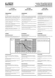
View PDF file for Technical Data - iProcesSmart.com
View PDF file for Technical Data - iProcesSmart.com
View PDF file for Technical Data - iProcesSmart.com

You also want an ePaper? Increase the reach of your titles
YUMPU automatically turns print PDFs into web optimized ePapers that Google loves.
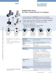
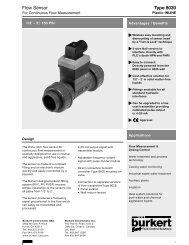
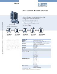
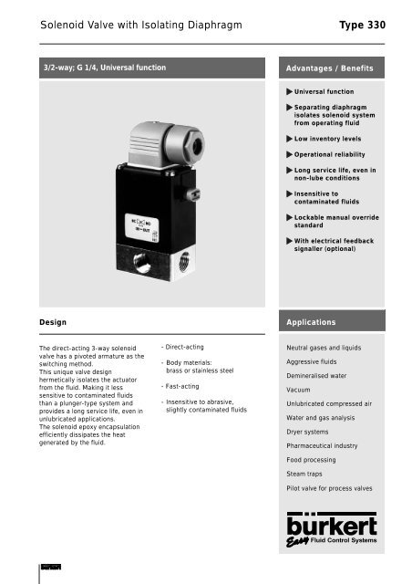
Solenoid Valve with Isolating Diaphragm Type 330<br />
3/2-way; G 1/4, Universal function<br />
Advantages / Benefits<br />
Universal function<br />
Separating diaphragm<br />
isolates solenoid system<br />
from operating fluid<br />
Low inventory levels<br />
Operational reliability<br />
Long service life, even in<br />
non-lube conditions<br />
Insensitive to<br />
contaminated fluids<br />
Lockable manual override<br />
standard<br />
With electrical feedback<br />
signaller (optional)<br />
Design<br />
Applications<br />
The direct-acting 3-way solenoid<br />
valve has a pivoted armature as the<br />
switching method.<br />
This unique valve design<br />
hermetically isolates the actuator<br />
from the fluid. Making it less<br />
sensitive to contaminated fluids<br />
than a plunger-type system and<br />
provides a long service life, even in<br />
unlubricated applications.<br />
The solenoid epoxy encapsulation<br />
efficiently dissipates the heat<br />
generated by the fluid.<br />
- Direct-acting<br />
- Body materials:<br />
brass or stainless steel<br />
- Fast-acting<br />
- Insensitive to abrasive,<br />
slightly contaminated fluids<br />
Neutral gases and liquids<br />
Aggressive fluids<br />
Demineralised water<br />
Vacuum<br />
Unlubricated <strong>com</strong>pressed air<br />
Water and gas analysis<br />
Dryer systems<br />
Pharmaceutical industry<br />
Food processing<br />
Steam traps<br />
Pilot valve <strong>for</strong> process valves<br />
Fluid Control Systems
Solenoid Valve <strong>for</strong> General Use<br />
with Isolating Diaphragm<br />
Type 330<br />
<strong>Technical</strong> <strong>Data</strong><br />
Circuit Function<br />
T 3/2-way valve,<br />
(Universal function)<br />
2<br />
1<br />
3<br />
Body Material<br />
Body and seat brass or stainless steel 1.4401<br />
Specifications<br />
Orifice Kv-Value 1) QNn-Value 1) Pressure Range Pressure Range Weight<br />
DN Water Air 2) Vacuum version<br />
[mm] [m 3 /h] [l/min] [bar] [bar] [kg]<br />
2 0,11 120 0 - 12 0,40<br />
3 0,16 175 0 - 8 0,40<br />
4 0,22 240 0 - 4 0 - 3 0,40<br />
1)<br />
Flow rate reduced by 20 % with direct current operation, 2) Measured with 6 bar upstream pressure and 1 bar pressure drop across the valve at<br />
+20 °C,<br />
All pressures quoted are gauge pressures with respect to the prevailing atmospheric pressure.<br />
Seal Materials / Fluids Handled / Temp.-Range<br />
NBR<br />
Operating <strong>Data</strong> (Valve)<br />
Neutral fluids, e.g. <strong>com</strong>pressed air, town gas,<br />
water, hydraulic oil, oils and fats without<br />
additives 0 to +90 °C<br />
Operating <strong>Data</strong> (Actuator)<br />
Operating voltages<br />
Voltage tolerance ±10 %<br />
24, 110, 220, 240 V/50 Hz,<br />
24 V/=<br />
(other voltages on request)<br />
EPDM<br />
FPM<br />
Oils and fat-free fluids, e.g. hot water<br />
alkaline washing and bleaching lyes<br />
-30 to +90 °C<br />
Hot air, oxygen, per-solutions, hot oils with<br />
additives -10 to +90 °C<br />
Power consumption<br />
Duty cycle<br />
AC 30 VA (inrush),<br />
5 VA/8 W (hold)<br />
DC 8 W<br />
100% continuously rated<br />
For more detailed in<strong>for</strong>mation please refer to resistance<br />
chart (Leaflet-No. 1896009).<br />
Max. ambient temperature +55 °C<br />
Max. viscosity 37 mm 2 /s<br />
Response times opening<br />
closing<br />
AC: 8-15 ms, DC: 10-20 ms<br />
AC: 8-15 ms, DC: 10-20 ms<br />
Cycling rate<br />
Rating with cable plug IP 65<br />
Installation / Accessories<br />
Installation<br />
approx. 1000 c.p.m.<br />
as required, but preferably<br />
with solenoid system<br />
upright<br />
Times measured at outlet A, from switching on until<br />
pressure rise to 90 % / pressure drops to 10 % at a max.<br />
working pressure of 6 bar.<br />
Electr. connection<br />
cable plug <strong>for</strong> 7 mm ø<br />
(supplied as standard)
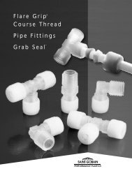
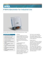
Type 330<br />
Dimensions in mm<br />
Standard version<br />
Valve with electrical feedback<br />
signaller Type 1060<br />
(on request)<br />
G 1/4<br />
G 1/4<br />
9<br />
9<br />
4 threads underneath<br />
M4 - 8 deep<br />
sealed screws
Solenoid Valve <strong>for</strong> General Use<br />
with Isolating Diaphragm<br />
Type 330<br />
Ordering Chart (Other Versions on Request)<br />
Circuit Orifice Flow Rate Port Pressure Body Seal Weight Voltage/ Order-No.<br />
Function Water Air 1) Connection Range Material Material Frequency<br />
DN Kv-Value QNn<br />
[mm] [m 3 /h] [l/min] (ISO 228) [bar] [kg] [V/Hz]<br />
T 2,0 0,09 96 G 1/4 0-12 Brass FPM 0,40 24/= 124 922 A<br />
0,11 120 G 1/4 0-12 Brass FPM 0,40 24/50 124 923 B<br />
0,11 120 G 1/4 0-12 Brass FPM 0,40 110/50 124 924 C<br />
0,11 120 G 1/4 0-12 Brass FPM 0,40 230/50 124 925 D<br />
0,11 120 G 1/4 0-12 Brass FPM 0,40 240/50 124 926 E<br />
0,09 96 G 1/4 0-12 Stainless FPM 0,40 24/= 124 932 C<br />
0,11 120 G 1/4 0-12 Stainless FPM 0,40 24/50 124 933 D<br />
0,11 120 G 1/4 0-12 Stainless FPM 0,40 110/50 124 934 E<br />
0,11 120 G 1/4 0-12 Stainless FPM 0,40 230/50 124 935 F<br />
0,11 120 G 1/4 0-12 Stainless FPM 0,40 240/50 124 936 G<br />
3,0 0,12 130 G 1/4 0- 8 Brass FPM 0,40 24/= 124 927 F<br />
0,16 175 G 1/4 0- 8 Brass FPM 0,40 24/50 124 928 Q<br />
0,16 175 G 1/4 0- 8 Brass FPM 0,40 110/50 124 929 R<br />
0,16 175 G 1/4 0- 8 Brass FPM 0,40 230/50 124 930 N<br />
0,16 175 G 1/4 0- 8 Brass FPM 0,40 240/50 124 931 B<br />
0,12 130 G 1/4 0- 8 Stainless FPM 0,40 24/= 124 937 H<br />
0,16 175 G 1/4 0- 8 Stainless FPM 0,40 24/50 124 938 J<br />
0,16 175 G 1/4 0- 8 Stainless FPM 0,40 110/50 124 939 K<br />
0,16 175 G 1/4 0- 8 Stainless FPM 0,40 230/50 124 940 Y<br />
0,16 175 G 1/4 0- 8 Stainless FPM 0,40 240/50 124 941 M<br />
Vacuum Version<br />
Circuit Orifice Flow Rate Port Pressure Body Seal Weight Voltage/ Order-No.<br />
Function Water Air 1) Connection Range Material Material Frequency<br />
DN Kv-Value QNn<br />
[mm] [m 3 /h] [l/min] (ISO 228) [bar] [kg] [V/Hz]<br />
T 4,0 0,17 185 G 1/4 0- 3 Brass NBR 0,40 24/= 124 942 N<br />
0,22 240 G 1/4 0- 3 Brass NBR 0,40 24/50 124 943 P<br />
0,22 240 G 1/4 0- 3 Brass NBR 0,40 110/50 124 944 Q<br />
0,22 240 G 1/4 0- 3 Brass NBR 0,40 230/50 124 945 R<br />
0,22 240 G 1/4 0- 3 Brass NBR 0,40 240/50 124 946 J<br />
In case of special requirements,<br />
We reserve the right to make technical changes without notice.<br />
please consult <strong>for</strong> advice. 710-GB/ 1-0069