Insertion Fitting S020/1500/1501 Insertion ... - iProcesSmart.com
Insertion Fitting S020/1500/1501 Insertion ... - iProcesSmart.com
Insertion Fitting S020/1500/1501 Insertion ... - iProcesSmart.com

You also want an ePaper? Increase the reach of your titles
YUMPU automatically turns print PDFs into web optimized ePapers that Google loves.
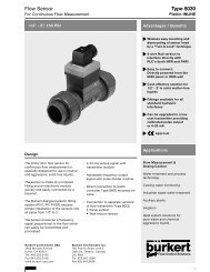
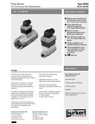
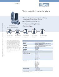
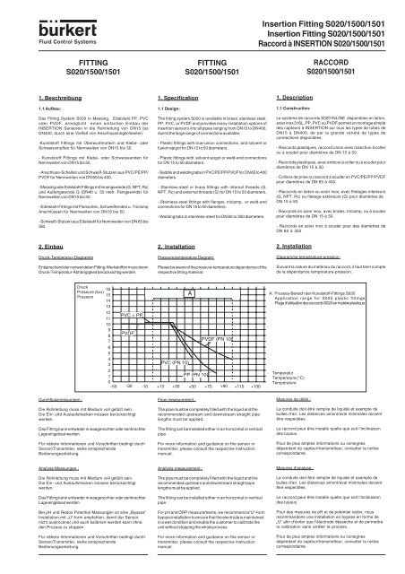
FITTING<strong>S020</strong>/<strong>1500</strong>/<strong>1501</strong>FITTING<strong>S020</strong>/<strong>1500</strong>/<strong>1501</strong><strong>Insertion</strong> <strong>Fitting</strong> <strong>S020</strong>/<strong>1500</strong>/<strong>1501</strong><strong>Insertion</strong> <strong>Fitting</strong> <strong>S020</strong>/<strong>1500</strong>/<strong>1501</strong>Raccord à INSERTION <strong>S020</strong>/<strong>1500</strong>/<strong>1501</strong>RACCORD<strong>S020</strong>/<strong>1500</strong>/<strong>1501</strong>1. Beschreibung1.1 Aufbau:1. Specification1.1 Design:1. Description1.1 Construction:Das <strong>Fitting</strong> System <strong>S020</strong> in Messing, Edelstahl,PP, PVCoder PVDF, ermöglicht einen einfachen Einbau derINSERTION Sensoren in die Rohrleitung von DN15 bisDN400, durch eine Vielfalt von Anschlussmöglichkeiten:-Kunststoff <strong>Fitting</strong>s mit Überwurfmuttern und Klebe- oderSchweissmuffen für Nennweiten von DN15 bis 50.- Kunststoff <strong>Fitting</strong>s mit Klebe- oder Schweissenden fürNennweiten von DN15 bis 50.- Anschluss-Schellen und Schweiß-Stutzen aus PVC/PE/PP/PVDF für Nennweiten von DN 65 bis 400.- Messing oder Edelstahl <strong>Fitting</strong>s mit Innengewinde (G, NPT, Rc)und Außengewinde G (DN40 u. 50 metr. Feingewinde) fürNennweiten von DN15 bis 50.- Edelstahl <strong>Fitting</strong>s mit Flanschen, Schweißenden u. TriclampAnschlüssen für Nennweiten von DN15 bis 50.- Schweiß-Stutzen aus Edelstahl für Nennweiten von DN 65 bis350.The fitting system <strong>S020</strong> is available in brass, stainless steel,PP, PVC, or PVDF and provides many installation options ofinsertion sensors into all pipes ranging from DN15 to DN400,due to the large range of connections available:- Plastic fittings with true-union connections, and solvent orfusion spigot for DN 15 to 50 diameters.- Plastic fittings with solvent spigot or weld-end connectionsfor DN 15 to 50 diameters.- Saddle and welding tabs in PVC/PE/PP/PVDF for DN 65 to 400diameters- Stainless-steel or brass fittings with internal threads (G,NPT, Rc) and external threads (G) for DN 15 to 50 diameters.- Stainless-steel fittings with flanges, triclamp, or weld-endconnections for DN 15 to 50 diameters.- Welding tabs in stainless-steel for DN 65 to 350 diameters.Le système de raccords <strong>S020</strong> INLINE disponibles en laiton,acier inox 316L, PP, PVC ou PVDF permet un montage simpledes capteurs à INSERTION sur tous les types de tubes deDN15 à DN400, de par la grande variété de types deconnections disponibles:- Raccords plastiques, raccord union avec manchon à collerou à souder pour diamètres de DN 15 à 50.- Raccords plastiques, avec embout à coller ou à souder pourdiamètres de DN 15 à 50.- Colliers de prise ou raccord à souder en PVC/PE/PP/PVDFpour diamètres de DN 65 à 400.- Raccords en laiton ou acier inox, avec filetages interieurs(G, NPT, Rc) ou filetage extérieurs (G) pour diamètres deDN 15 à 50.- Raccords en acier inox, avec brides, triclamp, ou à souderpour diamètres de DN 15 à 50.- Raccords en acier inox à souder pour des diamètres deDN 65 à 3502. EinbauDruck-Temperatur-DiagrammEntsprechend den verwendeten <strong>Fitting</strong>-Werkstoffen muss derenDruck-Temperatur-Abhängigkeit berücksichtig werden.2. InstallationPressure temperature Diagram:Please be aware of the pressure-temperature dependence of therespective fitting material.2. InstallationDiagramme température-pression:Suivant la nature du matériau du raccord, il faut tenir <strong>com</strong>ptede la dépendance température-pression.DruckPressure (bar)Pression161514131211109876543PVC + PPPVDFPVDF (PN 10)PVC (PN 10)21PP (PN 10)0-50 -30 -10 +10 +30 +50 +70 +90 +110 +130AA: Prozess-Bereich der Kunststoff-<strong>Fitting</strong>s <strong>S020</strong>Application range for <strong>S020</strong> plastic fittingsPlage d’utilisation des raccords <strong>S020</strong> en matière plastiqueTemperaturTemperature (°C)TempératureDurchflussmessungen :Die Rohrleitung muss mit Medium voll gefüllt sein.Die Ein- und Auslaufstrecken müssen berücksichtigtwerden.Das <strong>Fitting</strong> kann entweder in waagerechter oder senkrechterLage eingebaut werden.Für nähere Informationen und Vorschriften bedingt durchSensor/Transmitter, siehe entsprechendeBedienungsanleitung.Flow measurement :The pipe must be <strong>com</strong>pletely filled with the liquid and there<strong>com</strong>mended upstream and downstream straight pipelengths must be applied.The fitting can be installed either in an horizontal or verticalpipe.For more information and guidance on the sensor ortransmitter, please consult the respective instructionmanual.Mesures de débit :La conduite doit être remplie de liquide et exempte debulles d‘air. Les distances amont/aval minimales doiventêtre respectées.Le raccord peut être installé quelle que soit l‘inclinaisondes tuyaux.Pour de plus amples informations ou consignesdépendant du capteur/transmetteur, consulter la noticecorrespondante.Analyse Messungen :Die Rohrleitung muss mit Medium voll gefüllt sein.Die Ein- und Auslaufstrecken müssen berücksichtigtwerden.Das <strong>Fitting</strong> kann entweder in waagerechter oder senkrechterLage eingebaut werden.Bei pH und Redox Potential Messungen ist eine „Bypass“Installation mit „U“-form empfohlen, damit der Sensornicht austrocknet und auch kalibriert werden kann ohneden Prozess zu stoppen.Für nähere Informationen und Vorschriften bedingt durchSensor/Transmitter, siehe entsprechendeBedienungsanleitung.Analysis measurement :The pipe must be <strong>com</strong>pletely filled with the liquid and there<strong>com</strong>mended upstream and downstream straight pipelengths must be applied.The fitting can be installed either in an horizontal or verticalpipe.For pH and ORP measurements, we re<strong>com</strong>mend a“U“-formbypass installation to ensure that the electrode is maintainedin a wet condition and enable the customer to calibrate theunit without stopping the whole process.For more information and guidance on the sensor ortransmitter, please consult the respective instructionmanual.Mesures d‘analyse :La conduite doit être remplie de liquide et exempte debulles d‘air. Les distances amont/aval minimales doiventêtre respectées.Le raccord peut être installé quelle que soit l‘inclinaisondes tuyaux.Pour des mesures de pH et de potentiel redox, nousre<strong>com</strong>mandons une installation en bypass en forme de„U“ afin d‘éviter que l‘électrode déssèche et de permettrela calibration sans arrêter le process.Pour de plus amples informations ou consignesdépendant du capteur/transmetteur, consulter la noticecorrespondante.
2.1 EinbauAllgemein2.1 InstallationGeneral Information<strong>Insertion</strong> <strong>Fitting</strong> <strong>S020</strong>/<strong>1500</strong>/<strong>1501</strong><strong>Insertion</strong> <strong>Fitting</strong> <strong>S020</strong>/<strong>1500</strong>/<strong>1501</strong>Raccord à INSERTION <strong>S020</strong>/<strong>1500</strong>/<strong>1501</strong>2.1 MontageGénéralitésDas <strong>Fitting</strong> muss mit der Aussparung in gegengesetztenDurchfluss-Richtung installiert werden.The fitting has to be installed with the positioner in an oppositedirection to the flow.Le raccord doit être installé avec le détrompeur dans lesens opposé au fluide.Durchfluss RichtungFlow directionSens d’écoulementRohrleitungPipeConduiteAussparung zum EinbauPositioner to be used for installationDétrompeur à utiliser pour l’installationEdelstahl Schweiß-Stutzen (Abb.1)Stainless steel weld-ends (Fig.1)Raccords à souder en acier inoxydable (Fig.1)1. Einbauvorschriften des zu installierenden Sensors beachten.2. Loch von 28mm in die Rohrleitung bohren.3. Schweiß-Stutzen auf die Rohrleitung plazieren, so dass dieAussparung mit der Achse der Leitung in einer Reihe liegt.Rund um verschweißen.1. Take into account the installation guidelines of the sensor.2. Drill a hole of 28mm (1.10“) into the pipe.3. Place the fitting onto the pipe so that the positioner isaligned with the axis of the pipe, then weld the wholecircumference between the fitting and the pipe.1. Tenir <strong>com</strong>pte des consignes de montage du capteur àinstaller.2. Percer un trou de 28mm dans la conduite.3. Placer le raccord sur la conduite de telle sorte que ledétrompeur soit aligné avec l‘axe de la conduite. Soudersur toute la circonférence du raccord.Kunststoff-Schweiß-Stutzen (Abb.2)1. Einbauvorschriften des zu installierenden Sensorsbeachten.2. Loch von 40mm in die Rohrleitung bohren.3. Schweiß-Stutzen in die Rohrleitung bis Anstoß einlegenund so dass die Aussparung mit der Achse der Leitung ineiner Reihe liegt. Rund um verschweißen.Plastic weld-ends (Fig.2)1. Take into account the installation guidelines of the sensor.2. Drill a hole of 40mm (1.57“) into the pipe.3. Insert the fitting onto the pipe and ensure the positioner isaligned with the axis of the pipe, then weld the wholecircumference.Raccords à souder en matière plastique (Fig.2)1. Tenir <strong>com</strong>pte des consignes de montage du capteur àinstaller.2. Percer un trou de 40mm dans la conduite.3. Placer le raccord en butée sur la conduite de telle sorte quele détrompeur soit aligné avec l‘axe de la conduite. Souder surtoute la circonférence du raccord.Anschluss-Schellen (Abb.3)1. Einbauvorschriften des zu installierenden Sensorsbeachten.2. Loch von 32mm in die Rohrleitung bohren.3. Anschluss-Schelle an Rohrleitung festschrauben.Saddle (Fig.3)1. Take into account the installation guidelines of the sensor.2. Drill a hole of 32mm (1.26“) into the pipe.3. Fasten the saddle fitting to the pipe.Collier à prise (Fig.3)1. Tenir <strong>com</strong>pte des consignes de montage du capteur àinstaller.2. Percer un trou de 32mm dans la conduite.3. Fixer le collier de prise sur la conduite.Abb. 1Fig. 1SchweißungWeldSoudureAussparungPositionerDétrompeurØ 28 (1.10’’)Abb. 2Fig. 2SchweißungWeldSoudureAbb. 3Fig. 3BCAussparungPositionerDétrompeurØ 40 (1.57’’)ø32mm (1,26’’)ø DA
3. Technische Daten:3.1 Allgemeine Daten3. Technical Data:3.1 General Data<strong>Insertion</strong> <strong>Fitting</strong> <strong>S020</strong>/<strong>1500</strong>/<strong>1501</strong><strong>Insertion</strong> <strong>Fitting</strong> <strong>S020</strong>/<strong>1500</strong>/<strong>1501</strong>Raccord à INSERTION <strong>S020</strong>/<strong>1500</strong>/<strong>1501</strong>3. Caractéristiques techniques:3.1 Caractéristiques généralesNennweite:DN15 bis DN400Diameter : DN15 to DN400(1/2‘‘ to 16‘‘)Diamètre :DN15 à DN400Max. Mediumstemperatur:<strong>Fitting</strong>: T°PVC 0 bis 50°CPP 0 bis 80°CPVDF *-25 bis +100°CEdelstahl * -20 bis +150°CMessing *-20 bis +150°C* vom Elektronikmodul abhängigMaximum fluid temperature :<strong>Fitting</strong>: T°PVC 0 up to 50°CPP 0 up to 80°CPVDF *-25 up to +100°CStainless steel *-20 up to +150°CBrass *-20 up to +150°C* depends on the associated electronic moduleTempérature max. du fluide:<strong>Fitting</strong>: T°PVC 0 à 50°CPP 0 à 80°CPVDF *-25 à +100°CAcier inoxydable *-20 à +150°CLaiton *-20 à +150°C* fonction de l‘électronique associéeDruckklasse:PN10 (Kunststoff)PN16 (Metall)Pressure Class:PN10 (Plastic)PN16 (Metal)Classe de pression:PN10 (Plastique)PN16 (Métal)Achtung: Die maximalen Mediums-Temperatur und-Druck können auch vom Sensor abhängig sein (z.B.PN6 hauptsächlich).Siehe dazu die entsprechende Bedienungsanleitung.Caution: Temperature and pressure limits may dependon the sensor (usually PN6 for example).Please refer to the appropriate instruction manual formore details.Attention: les valeurs maximales de température etde pression peuvent également dépendre descaractéristiques du capteur (par exemple PN6 engénéral). Se référer au manuel d‘utilisation approprié.O-Ringe:FPM oder EPDMO-Rings:FPM or EPDMJoints toriques:FPM ou EPDM3.2 K-Faktor: <strong>Fitting</strong> mit Durchfluss-Sensor/ Transmitter3.2 K-factor: <strong>Fitting</strong> with flow sensor/ transmitter3.2 Facteur K: raccord avec capteur/transmetteur de débit<strong>S020</strong> VA / SSt316 / Inox MS / Brass / Laiton PVC PP PVDFMit / with / avec Mit / with / avec Mit / with / avec Mit / with / avec Mit / with / avecDN 8020/8024/ 8040/8045/ 8020/8024/ 8040/8045/ 8020/8024/ 8040/8045/ 8020/8024/ 8040/8045/ 8020/8024/ 8040/8045/8025 8045 HT 8025 8045 HT 8025 8045 HT 8025 8045 HT 8025 8045 HT15 109.9 1.691 109.9 1.691 119.7 1.332 117.6 1.29 129.4 1.21320 64.02 1.984 64.02 1.984 81.05 1.513 75.08 1.437 81.20 1.36525 48.3 2.848 48.3 2.848 56.59 2.258 53.58 2.212 60.32 2.03532 30.93 4.32 30.93 4.32 29.87 4.287 29.02 4.299 31.88 4.02540 19.48 6.68 19.48 6.68 18.64 7.30 17.41 7.16 19.37 6.8850 11.18 11.24 11.18 11.24 10.66 12.47 10.29 12.19 11.07 11.46Immer mit kurzer Sensor-Ausführung / Always with short sensor version / Uniquement avec capteur version courteTyp / Type <strong>1500</strong> welding tab <strong>1501</strong> saddle PP <strong>1501</strong> welding tab <strong>1501</strong> saddle <strong>1501</strong> welding tabVA / SSt / Inox PVC PP/PE PP PVDFMS/ Brass /LaitonDN Mit / with / avec Mit / with / avec Mit / with / avec Mit / with / avec Mit / with / avecDN 8020/8024/ 8040/8045/ 8020/8024/ 8040/8045/ 8020/8024/ 8040/8045/ 8020/8024/ 8040/8045/ 8025 8040/8045/8025 8045 HT 8025 8045 HT 8025 8045 HT 8025 8045 HT 8045 HT65 7.86 (S) 20.04 (S) 11.18 (L) 14.49 (L) 8.32 (S) 17.78 (S) x x 5.53 (S) 24.11 (S)80 5.52 (S) 28.51(S) 7.38 (L) 21.32 (L) 5.49 (S) 25.61 (S) 7.8 (L) 20.40 (L) 3.65 (S) 40.75 (S)100 3.20 (S) 49.22 (S) 4.83 (L) 33.04 (L) 3.51 (S) 38.12 (S) 5.29 (L) 30.38 (L) 2.34 (S) 70.45 (S)110 x x 3.45 (L) 44.69 (L) x x x x x x125 2.00 (S) 78.0 (S) 2.55 (L) 63.65 (L) 2.66 (L) 81.7 (L) 3.10 (L) 52.11 (L) x x150 1.32 (S) 98.4 (S) 1.67(L) 136.6 (L) 2.12 (L) 103.0 (L) 2.03 (L) 78.81 (L) x x180 x x 1.08 (L) 196.8 (L) x x 1.37 (L) 116.0 (L) x x200 0.72 (S) 155.0 (S) 0.80 (L) 290.0 (L) 0.98 (L) 223.5 (L) 1.07 (L) 146.8 (L) x x250 0.50 (L) 311 (L) x x 0.63 (L) 347 (L) x x x x300 0.35 (L) 447 (L) x x 0.42 (L) 510 (L) x x x x350 0.26 (L) 609 (L) x x 0.3 (L) 705 (L) x x x x400 x x x x 0.23 (L) 931 (L) x x x xX : nicht verfügbar / not available / non disponible(S) : Kurze Sensor Ausführung / short sensor version / capteur version courte(L) : Lange Sensor Ausführung / Long sensor version / capteur version longueBemerkungK-Faktor in Pulse/ US Gallon = K (Pulse/l) x 3.785K-Faktor in Pulse/ UK Gallon = K (Pulse/l) x 4.546Unter Referenzbedingungen, d.h. Messmedium Wasser,Umgebungs- und Wassertemperatur 20°C, Berücksichtigungder Mindestein- und Auslaufstrecken, angepassteRohrleitungsabmessungen.NoteK-Factor in pulse/ US Gallon = K (pulse/l) x 3.785K-Factor in pulse/ UK Gallon = K (pulse/l) x 4.546Under reference conditions, i.e. measuring fluid water,ambient and water temperatures of 20°C, applying the minimuminlet and outlet pipe lengths, and appropriate pipe dimensions.Remarque:Facteur K en impulsion/ gallon US = K (impulsion/l) x 3.785Facteur K en impulsion/ gallon UK = K (impulsion/l) x 4.546Dans les conditions de référence, à savoir: fluide eau,températures du fluide et ambiante 20°C, distances amont etaval respectées, dimensions des tubes adaptées.
4. Abmessungen4.1: Edelstahl, Messing DN15 bis DN504. Dimensions4.1: Stainless-steel, brass DN15 to DN504. Dimensions4.1: Acier inox, laiton DN15 à DN50<strong>Insertion</strong> <strong>Fitting</strong> <strong>S020</strong>/<strong>1500</strong>/<strong>1501</strong><strong>Insertion</strong> <strong>Fitting</strong> <strong>S020</strong>/<strong>1500</strong>/<strong>1501</strong>Raccord à INSERTION <strong>S020</strong>/<strong>1500</strong>/<strong>1501</strong>FG2G1HM K NABL2CL1DDIN 3202-F1JIE[mm][1]SchweißendeWeld-endsEmbouts à souder(ISO 4200)[2]AußengewindeExternal threadFiletage extérieur( G )[3]InnengewindeInternal threadTaraudage( G, NPT, Rc )[4]mit Triclampwith TriclampTriclamp(ISO 2852)[1] Länge / Length /Longueur [2] und / and / et [3] Triclamp [4] Flansch/Flange/Bride [5]DN Außen-ø Dicke A B C D E E F G1 L1 G2 L2 H Standard* I J K M Nexternal ø thickness (DIN) (JIS) standard*ø extérieur épaisseur (ANSI) Norme*G 1/2“ 16.0 DIN 23.5 4x14.0 65.0 95 45.015 21.3 1.6 84 84 85 130 130 152 80.3 NPT 1/2“ 17.0 G3/4“ 11.5 34.0 ANSI 23.5 4x15.8 60.3 89 34.9Rc 1/2“ 15.0 JIS 23.5 4x15.0 70.0 95 51.0G 3/4“ 17.0 DIN 28.5 4x14.0 75.0 105 58.020 26.9 1.6 94 94 95 150 150 178 77.8 NPT 3/4“ 18.3 G1“ 13.5 50.5 ANSI 28.5 4x15.8 69.8 99 42.9Rc 3/4“ 16.3 JIS 28.5 4x15.0 75.0 100 56.0G1“ 23.5 DIN 28.5 4x14.0 85.0 115 68.025 33.7 2.0 104 104 105 160 160 216 78.0 NPT1“ 18.0 G 1 1/4“ 14.0 50.5 ANSI 28.5 4x15.8 79.4 108 50.8Rc1“ 18.0 JIS 28.5 4x19.0 90.0 125 67.0G 1 1/4“ 23.5 DIN 31.0 4x18.0 100.0 140 78.032 42.4 2.0 119 119 120 180 180 229 81.6 NPT 1 1/4“ 21.0 G 1/2“ 18.0 50.5 ANSI 31.0 4x15.8 88.9 117 63.5Rc 1 1/4“ 21.0 JIS 31.0 4x19.0 100.00 135 76.0G 1 1/2“ 23.5 DIN 36.0 4x18.0 110.0 150 88.040 48.3 2.0 129 129 130 200 200 241 85.4 NPT 1 1/2“ 20.0 M55x2 19.0 64.0 ANSI 36.0 4x15.8 98.4 127 73.0Rc 1 1/2“ 19.0 JIS 36.0 4x19.0 105.0 140 81.0G2“ 27.5 DIN 41.0 4x18.0 125.0 165 102.050 60.3 2.6 149 149 150 230 230 267 91.5 NPT2“ 24.0 M64x2 20.0 77.5 ANSI 41.0 4x19.0 120.6 152 92.1Rc 2“ 24.0 JIS 41.0 4x19.0 120.0 155 96.0[5]Mit FlanschenWith flangesA brides* DIN 2501/2633, Einbaulänge nach DIN 3202-F1;* ANSI B16-5-1988, Einbaulänge nach DIN 3202-F1;* JIS 10K, Einbaulänge nach ANSI B16-10* DIN 2501/2633, length according to DIN 3202-F1;* ANSI B16-5-1988, length according to DIN 3202-F1;* JIS 10K, length according to ANSI B16-10* DIN 2501/2633, longueur selon DIN 3202-F1;* ANSI B16-5-1988, longueur selon DIN 3202-F1;* JIS 10K, longueur selon ANSI B16-104.2 VA-Schweiß-Stutzen mit Radius DN65 bis DN3504.2 SSt weld with radius DN65 to DN3504.2 Raccords à souder Inox avec courbure DN65 à DN350Werkstoff:1.4404 (DIN)316L (B.S.)Material: 1.4404 (DIN)316L (B.S.)Matériau: 1.4404 (DIN)316L (B.S.)N.B.:Kurze Durchfluss Sensor Ausführung für DN65 bis DN200Lange Durchfluss Sensor Ausführung für DN250 bis DN350AN.B.: Short flow Sensor version for DN65 to DN200Long flow Sensor version for DN250 to DN350N.B.: Capteur de débit version courte pour DN65 à DN200Capteur de débit version longue pour DN250 à DN350Rø 27.6ø 33.6DN 65 80 100 125 150 200 250 300 350A 54.52 53.07 50.71 48.24 45.73 41.01 73.64 67.83 63.94R 36.65 44.45 57.15 70.65 84.15 109.55 136.55 161.95 177.80
4.3 PVC-PP-PVDF DN15 bis DN50 4.3 PVC-PP-PVDF DN15 to DN50 4.3 PVC-PP-PVDF DN15 à DN50<strong>Insertion</strong> <strong>Fitting</strong> <strong>S020</strong>/<strong>1500</strong>/<strong>1501</strong><strong>Insertion</strong> <strong>Fitting</strong> <strong>S020</strong>/<strong>1500</strong>/<strong>1501</strong>Raccord à INSERTION <strong>S020</strong>/<strong>1500</strong>/<strong>1501</strong>[6]ÜberwurfmutterTrue union connectionRaccord unionBL1L3LøCøAøCEL2BD[7]Klebe- oder SchweißmuffenSolvent/fusion spigotAvec manchon à coller / à souder[6] [7]DN B ø C ø A L L1 L3 D L2 EDIN ANSI JIS DIN ANSI* JIS* PVC PP/PVDF PVC PP/PVDF15 80.4 20 21.3 18.40 43 128 130.0 129 90 96 17.5 90 85 16.5 14<strong>Fitting</strong> für Durchfluss und Analyse (pH und ORP kompakte Ausführung und getrennteAusführung lange Entfernung)<strong>Fitting</strong> for flow and analysis (pH and ORP <strong>com</strong>pact version and remote version longdistance)Raccord pour mesure de débit et d’analyse (pH et POR: version <strong>com</strong>pacte et versionséparée longue distance)20 77.8 25 26.7 26.45 53 144 145.6 145 100 106 17.5 100 92 20.0 1625 78.0 32 33.4 32.55 60 160 161.4 161 110 116 21.5 110 95 23.0 1832 81.4 40 42.2 38.60 74 168 170.0 169 110 116 27.5 110 100 27.5 2040 85.2 50 48.3 48.70 83 188 190.2 190 120 127 31.5 120 106 30.0 2350 91.5 63 60.3 60.80 103 212 213.6 213 130 136 39.5 130 110 37.0 27*Nur für PVC Überwurfmutter / Only for PVC True union / Uniquement pour raccord union en PVC[6] [7]DN B ø C ø A L L1 L3 D L2 EDIN ANSI JIS DIN ANSI* JIS* PVC PP/PVDF PVC PP/PVDF15 81.4 20 - - - - - - 74 148 - - - - - - 110 116 - - - - - - - - - - - - - - -<strong>Fitting</strong> für Analyse (Leitfähigkeit: kompakte und getrennte Ausführungen - pH und ORP :getrennte Ausführung kurze Entfernung)<strong>Fitting</strong> analysis (Conductivity: <strong>com</strong>pact and remote versions - pH and ORP: remote versionshort distance)Raccord pour mesure d’analyse (Conductivité: versions <strong>com</strong>pacte et séparée - pH et POR:version séparée courte distance)20 81.4 25 - - - - - - 74 154 - - - - - - 110 116 - - - - - - - - - - - - - - -25 81.4 32 - - - - - - 74 160 - - - - - - 110 116 - - - - - - - - - - - - - - -32 81.4 40 42.2 38.60 74 168 170.0 169 110 116 27.5 110 100 27.5 2040 85.2 50 48.3 48.70 83 188 190.2 190 120 127 31.5 120 106 30.0 2350 91.5 63 60.3 60.80 103 212 213.6 213 130 136 39.5 130 110 37.0 27*Nur für PVC Überwurfmutter / Only for PVC True union / Uniquement pour raccord union en PVC4.4 DN65 bis DN400 4.4 DN65 to DN400 4.4 DN65 à DN400ø DAAnschluss-Schellen PPSaddle PPCollier PPBCGehäusewerkstoff / Body material / Matériau du corps: PP/PVCDichtwerkstoff / Seal material / Matériau d’étanchéité: EPDMN.B.: Nur mit langer Durchfluss-Sensor-AusführungOnly with long flow sensor versionUniquement avec le capteur de débit version longueDN 50 65 80 100 110 125 150 180 200A 116.0 129.0 144.0 166.0 181.0 196.0 216.0 266.0 290.0B 116.0 115.0 119.0 124.0 120.0 127.0 137.0 161.0 173.0C 155.0 160.0 171.0 187.0 191.0 205.0 225.0 271.0 297.0øD 63.0 75.0 90.0 110.0 125.0 140.0 160.0 200.0 225.0PE, PP, PVDFSchweiß-Stutzen / PE, PP, PVDF Fusion spigot / Raccord à souder PE, PP, PVDFDN 65 80 100 150 200 250 300 350 400A 72.5 72.5 72.5 102 102 102 102 102 102B 13 15.6 19 27.7 38.9 48.4 54.5 61.3 69.1PEAC - - - - - - 5 10 16 21 24 28 31.5B 13 15.6 19 27.7 38.9 48.4 54.5 61.3 - - -PPB CC - - - - - - 5 10 16 21 24 28 - - -B 10.4 2.5 15.2 - - - - - - - - - - - - - - - - - -ø 39 PVDFC - - - - - - 6 - - - - - - - - - - - - - - - - - -N.B.:-Kurze Durchfluss-Sensor-Ausführungfür DN65 bis DN100Lange Durchfluss-Sensor-Ausführungfür DN150 bis DN400-Short flow Sensor versionfor DN65 to DN100Long flow Sensor versionfor DN150 to DN400-Capteur de débit version courtepour DN65 à DN100Capteur de débit version longuepour DN150 à DN400
<strong>Insertion</strong> <strong>Fitting</strong> <strong>S020</strong>/<strong>1500</strong>/<strong>1501</strong><strong>Insertion</strong> <strong>Fitting</strong> <strong>S020</strong>/<strong>1500</strong>/<strong>1501</strong>Raccord à INSERTION <strong>S020</strong>/<strong>1500</strong>/<strong>1501</strong>5. <strong>Fitting</strong> Bestelltabelle / Ordering Chart for <strong>Fitting</strong>s / Tableau de <strong>com</strong>mande des raccordsEdelstahl / Stainless-Steel / Acier InoxBestell-Nr. / Order code / Référence de <strong>com</strong>mandeTechnische Daten / Specifications / Spécifications DN 15 DN 20 DN 25 DN 32 DN 40 DN 50Schweißende / Welding ends / Embouts à souder 428760 428761 428762 428763 428764 428765Außengewinde G / External Thread G / Filetage extérieur G 428754 428755 428756 428757 428758 428759G-Innengewinde / G-Internal thread / Taraudage G 428736 428737 428738 428739 428740 428741NPT-Innengewinde / NPT-Internal thread / Taraudage NPT 428742 428743 428744 428745 428746 428747Rc ISO7-Innengewinde /Rc ISO7-Internal thread / Taraudage Rc ISO7 428748 428749 428750 428751 428752 428753Mit Triclamp / with triclamp / Raccord Triclamp (ISO 2852) 428766 428767 428768 428769 428770 428771Mit DIN Flanschen / With DIN flanges / A brides DIN (DIN 2501) 428772 428773 428774 428775 428776 428777Mit (JIS 10K) Flanschen / With (JIS 10K) flanges / A brides (JIS 10K) 431053 431054 431055 431056 431057 431058Mit ANSI Flanschen / With ANSI flanges / A brides ANSI (ANSI B16-5-1998) 428778 428779 428780 428781 408782 428783Technische Daten / Specifications / Spécifications DN 65 DN 80 DN 100 DN 125 DN 150 DN 200 DN 250 DN300 DN350Schweiß-Stutzen / Welding tab/ Raccord à souder 418112 418113 418114 418115 418116 418117 418756 420070 416637Messing / Brass / LaitonBestell-Nr. / Order code / Référence de <strong>com</strong>mandeTechnische Daten / Specifications / Spécifications DN 15 DN 20 DN 25 DN 32 DN40 DN 50Außengewinde G / External Thread G / Filetage extérieur G 428730 428731 428732 428733 428734 428735G-Innengewinde / G-Internal thread / Taraudage G 428712 428713 428714 428715 428716 428717NPT-Innengewinde / NPT-Internal thread / Taraudage NPT 428718 428719 418720 428721 428722 428723Rc ISO7-Innengewinde / Rc ISO7-Internal thread / Taraudage Rc ISO7 428724 428725 428726 428727 428728 428729PVCBestell-Nr. / Order code / Référence de <strong>com</strong>mandeTechnische Daten / Specifications / Spécifications DN 15 DN 20 DN 25 DN 32 DN40 DN 50Überwurfmutter ISO/ True union connection ISO / raccord union ISO 428670 428671 428672 428673 428674 428675Überwurfmutter ASTM/ True union connection ASTM/ raccord union ASTM 428682 428683 428684 428685 428686 428687Überwurfmutter JIS/ True union connection JIS/ raccord union JIS 429078 429079 429080 429081 429082 429083Klebe oder Schweißmuffe/Solvent or fusion spigot/ manchon à coller ou à souder 428676 428677 428678 428679 428680 428681Für Analyse / for analysis / pour analyse 430837 430838 430839 428673 428674 428675PPBestell-Nr. / Order code / Référence de <strong>com</strong>mandeTechnische Daten / Specifications / Spécifications DN 15 DN 20 DN 25 DN 32 DN40 DN 50Überwurfmutter ISO/ True union connection ISO/ raccord union ISO 428688 428689 428690 428691 428692 428693Klebe oder Schweißmuffe/Solvent or fusion spigot/ manchon à coller ou à souder 428694 428695 428696 428697 428698 428699Für Analyse / for analysis / pour analyse 430840 430841 430842 428691 428692 428693Technische Daten / Specifications / Spécifications DN 65 DN 80 DN 100 DN 150 DN 200 DN 250 DN300 DN350 DN400Schweiß-Stutzen / Fusion spigot / Raccord à souder 418650 418651 418652 418653 418654 418655 418656 418657 -Technische Daten / Specifications / Spécifications DN 50 DN 65 DN 80 DN 100 DN 110 DN 125 DN 150 DN180 DN 200Anschluss-Schellen / Saddle / Collier 425138 425139 425140 425141 425142 425143 425144 433873 425416PVDFBestell-Nr. / Order code / Référence de <strong>com</strong>mandeTechnische Daten / Specifications / Spécifications DN 15 DN 20 DN 25 DN 32 DN40 DN 50Überwurfmutter ISO / True union connection ISO/ raccord union ISO 428700 428701 428702 428703 428704 428705Klebe oder Schweißmuffe/Solvent or fusion spigot/ manchon à coller ou à souder 428706 428707 428708 428709 428710 428711Für Analyse / for analysis / pour analyse 430843 430844 430845 428703 428704 428705Technische Daten / Specifications / Spécifications DN 65 DN 80 DN 100 DN 150 DN 200 DN 250 DN300 DN350 DN400Schweiß-Stutzen / Fusion spigot / Raccord à souder 418658 418659 418660 - - - - - -PEBestell-Nr. / Order code / Référence de <strong>com</strong>mandeTechnische Daten / Specifications / Spécifications DN 65 DN 80 DN 100 DN 150 DN 200 DN 250 DN300 DN350 DN400Schweiß-Stutzen / Fusion spigot / Raccord à souder 418642 418643 418644 418645 418646 418647 418648 418649 418598© Bürkert 1998Technische Änderung vorbehaltenSubject to change without notice00429633-Ind_BSous réserve de modifications techniques