WB Troubleshooting Form 2.pdf
WB Troubleshooting Form 2.pdf
WB Troubleshooting Form 2.pdf

Create successful ePaper yourself
Turn your PDF publications into a flip-book with our unique Google optimized e-Paper software.
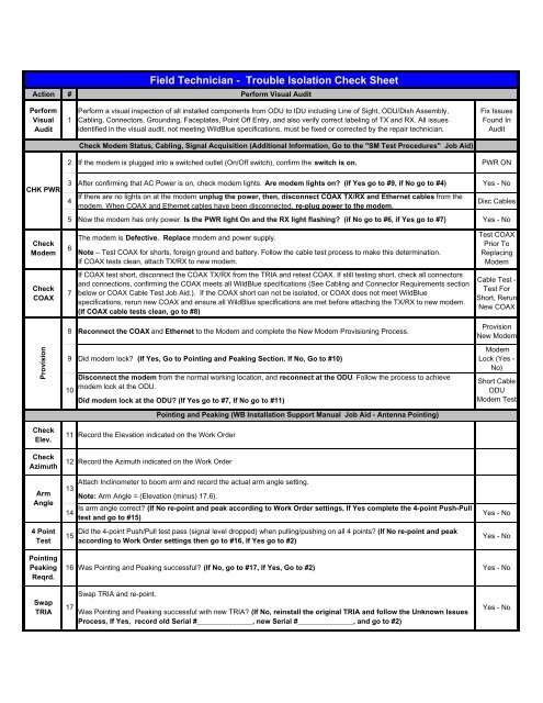
Field Technician - Trouble Isolation Check Sheet<br />
Action # Perform Visual Audit<br />
Perform<br />
Visual<br />
Audit<br />
1<br />
Perform a visual inspection of all installed components from ODU to IDU including Line of Sight, ODU/Dish Assembly,<br />
Cabling, Connectors, Grounding, Faceplates, Point Off Entry, and also verify correct labeling of TX and RX. All issues<br />
identified in the visual audit, not meeting WildBlue specifications, must be fixed or corrected by the repair technician.<br />
Fix Issues<br />
Found In<br />
Audit<br />
Check Modem Status, Cabling, Signal Acquisition (Additional Information, Go to the "SM Test Procedures" Job Aid)<br />
2 If the modem is plugged into a switched outlet (On/Off switch), confirm the switch is on. PWR ON<br />
CHK PWR<br />
3 After confirming that AC Power is on, check modem lights. Are modem lights on (If Yes go to #9, if No go to #4) Yes - No<br />
4<br />
If there are no lights on at the modem unplug the power, then, disconnect COAX TX/RX and Ethernet cables from the<br />
modem. When COAX and Ethernet cables have been disconnected, re-plug power to the modem.<br />
Disc Cables<br />
5 Now the modem has only power. Is the PWR light On and the RX light flashing (if No go to #6, if Yes go to #7) Yes - No<br />
Check<br />
The modem is Defective. Replace modem and power supply.<br />
Note – Test COAX for shorts, foreign ground and battery. Follow the cable test process to make this determination.<br />
If COAX tests clean, attach TX/RX to new modem.<br />
Test COAX<br />
Prior To<br />
Replacing<br />
Modem<br />
Modem 6 10<br />
Check<br />
COAX<br />
7<br />
If COAX test short, disconnect the COAX TX/RX from the TRIA and retest COAX. If still testing short, check all connectors<br />
and connections, confirming the COAX meets all WildBlue specifications (See Cabling and Connector Requirements section<br />
below or COAX Cable Test Job Aid.). If the COAX short can not be isolated, or COAX does not meet WildBlue<br />
specifications, rerun new COAX and ensure all WildBlue specifications are met before attaching the TX/RX to new modem.<br />
(If COAX cable tests clean, go to #8)<br />
Cable Test -<br />
Test For<br />
Short, Rerun<br />
New COAX<br />
Provision<br />
Check<br />
Elev.<br />
Check<br />
Azimuth<br />
Arm<br />
Angle<br />
4 Point<br />
Test<br />
8 Reconnect the COAX and Ethernet to the Modem and complete the New Modem Provisioning Process.<br />
9 Did modem lock (If Yes, Go to Pointing and Peaking Section. If No, Go to #10)<br />
Disconnect the modem from the normal working location, and reconnect at the ODU. Follow the process to achieve<br />
modem lock at the ODU.<br />
Did modem lock at the ODU (If Yes go to #7, If No go to #11)<br />
11 Record the Elevation indicated on the Work Order<br />
12 Record the Azimuth indicated on the Work Order<br />
13<br />
14<br />
15<br />
Attach Inclinometer to boom arm and record the actual arm angle setting.<br />
Note: Arm Angle = (Elevation (minus) 17.6).<br />
Pointing and Peaking (<strong>WB</strong> Installation Support Manual Job Aid - Antenna Pointing)<br />
Is arm angle correct (If No re-point and peak according to Work Order settings, If Yes complete the 4-point Push-Pull<br />
test and go to #15)<br />
Did the 4-point Push/Pull test pass (signal level dropped) when pulling/pushing on all 4 points (If No re-point and peak<br />
according to Work Order settings then go to #16, If Yes go to #2)<br />
Provision<br />
New Modem<br />
Modem<br />
Lock (Yes -<br />
No)<br />
Short Cable<br />
ODU<br />
Modem Test<br />
Yes - No<br />
Yes - No<br />
Pointing<br />
Peaking<br />
Reqrd.<br />
16 Was Pointing and Peaking successful (If No, go to #17, If Yes, Go to #2) Yes - No<br />
Swap<br />
TRIA<br />
17<br />
Swap TRIA and re-point.<br />
Was Pointing and Peaking successful with new TRIA (If No, reinstall the original TRIA and follow the Unknown Issues<br />
Process, If Yes, record old Serial #______________, new Serial #______________, and go to #2)<br />
Yes - No
Cabling and Connector Requirements<br />
Cable Length<br />
Cable Spec.<br />
Cable Loops<br />
Connectors<br />
Grnd Block<br />
Ground Runs<br />
Cable length can NOT exceed 150 ft, else new Cable will have to be re-run. How long (feet) is the cable run<br />
All cable must be High Freq. (2.2 GHz) COAX cable and on the <strong>WB</strong> Approved List (Approved COAX Cable Bulletin). What is<br />
the Model# of the COAX Cable being used/installed<br />
WildBlue requires all Loops (<strong>WB</strong> approved cable) to be no smaller than 11 inches, or a have a bend radius no smaller then<br />
5.5 inches. What is the Loop Size of your cable<br />
All COAX cable must be terminated with RG6 High Frequency Compression Connectors that are fully weather sealed. Are<br />
Connectors Compliant (If not Compliant, Connectors must be replaced with approved connectors)<br />
Check Grounding and Grounding Block<br />
All COAX cable should terminate on a properly grounded High Frequency Dual Grounding block.<br />
1) For cable runs of less than 20 feet, the Bonding Cable can be #10 gauge copper or a #8 gauge Aluminum wire.<br />
2) For grounding runs that exceed 20 feet, from the DC grounding block to the home ground, an 8 foot grounding rod must be<br />
installed within 20 feet of ground block, and #6 gauge solid copper grounding wire must be run to the home ground from the<br />
rod.<br />
3) For all groundings, the total length of the cable run must exceed the ground run.<br />
4) Grounding and Bonding is required on all WildBlue installs for both the Antenna and the COAX cable.<br />
5) Water (metal) pipe ground should be within five feet of the water entry to the structure and water pipe and in direct earth<br />
contact for at least 10 feet before entering property.<br />
SVT <strong>Troubleshooting</strong> Matrix<br />
Yes - No<br />
DSSNR<br />
Downstream<br />
Signal-to-Noise<br />
(First)<br />
DSCHPWR<br />
Downstream Channel<br />
Power<br />
(Second)<br />
USTXPWR<br />
Upstream Transmit<br />
Power<br />
(Third)<br />
USSNR<br />
Upstream Signalto-Noise<br />
(Fourth)<br />
Possible Issue<br />
Red - DSSNR<br />
Troubleshoot<br />
1. Line of Site<br />
2. Misassembled Dish<br />
3. MisPointed<br />
4. Bad/Non-Compliant Cable<br />
5. Bad TRIA (resolve 1-4 first)<br />
Green<br />
Red – DSCHPWR<br />
Troubleshoot<br />
1. Long Cable Run<br />
2. Connectors/Ground Block<br />
3. Bad TRIA<br />
1st<br />
DSSNR<br />
2nd<br />
DSCHPWR<br />
3rd<br />
USTXPWR<br />
4th<br />
USSNR<br />
1<br />
2<br />
3<br />
4<br />
Green<br />
Green<br />
Green<br />
Green<br />
Green<br />
Green<br />
SVT <strong>Troubleshooting</strong> Matrix Explained<br />
Downstream Signal-to-Noise - The technician resolves all DSSNR issues (possible causes appear in the first row of the<br />
chart above) before addressing any other SVT failures.<br />
Status (if known) Red____ Green ____<br />
Downstream Channel Power - If DSSNR is green, and DSRXPWR is red, the technician resolves all DSPXPWR issues<br />
(possible causes appear in the second row of the chart above) before addressing any other SVT failures.<br />
Status (if known) Red____ Green ____<br />
Upstream Transmit Power - If DSSNR and DSRXPWR are green, and USTXPWR is red, the technician resolves all<br />
USTXPWR issues (possible causes appear in the third row of the chart above) before attempting any other SVT failures.<br />
Status (if known) Red____ Green ____<br />
Upstream Signal-to-Noise - If DSSNR, DSRXPWR, and USTXPWR are green, and USSNR is red, the technician resolves<br />
all USSNR issues (possible causes appear in the fourth row of the chart above).<br />
Status (if known) Red____ Green ____<br />
Red - USTXPWR<br />
Troubleshoot<br />
Green<br />
Green<br />
Red – USSNR<br />
Troubleshoot<br />
Green<br />
1. Bad/Non-Compliant Cable<br />
2. Connectors/Ground Block<br />
3. Misassembled Dish<br />
4. Bad TRIA<br />
1. Bad TRIA<br />
OK