Development of Feed for Parabolic Reflector Antenna - IJET
Development of Feed for Parabolic Reflector Antenna - IJET
Development of Feed for Parabolic Reflector Antenna - IJET

You also want an ePaper? Increase the reach of your titles
YUMPU automatically turns print PDFs into web optimized ePapers that Google loves.
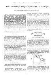
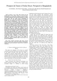
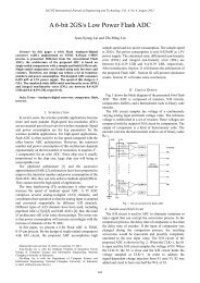
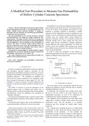
International Journal <strong>of</strong> Engineering and Technology Vol. 1, No. 1, April, 2009<br />
1793-8236<br />
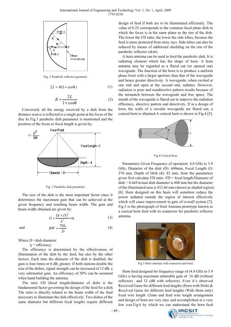
Fig. 2 <strong>Parabolic</strong> reflector geometry<br />
2 L = R(1+ cos θ )<br />
(1)<br />
2L<br />
R = (2)<br />
1 + cosθ<br />
Conversely all the energy received by a dish from the<br />
distance source is reflected to a single point at the focus <strong>of</strong> the<br />
disc In Fig.3 parabolic dish parameter is mentioned and the<br />
position <strong>of</strong> the focus or focal length is given by:<br />
design <strong>of</strong> feed if both are to be illuminated efficiently. The<br />
value <strong>of</strong> 0.25 corresponds to the common focal plane dish in<br />
which the focus is in the same plane as the rim <strong>of</strong> the dish.<br />
The lower the f/D ratio, the lower the side lobes, because the<br />
feed is more protected from stray rays. Side lobes can also be<br />
reduced by means <strong>of</strong> additional shielding on the rim <strong>of</strong> the<br />
parabolic reflector (skirt).<br />
A horn antenna can be used to feed the parabolic dish. It is<br />
radiating element which has the shape <strong>of</strong> horn. A horn<br />
antenna may be regarded as a flared out (or opened out)<br />
waveguide. The function <strong>of</strong> the horn is to produce a uni<strong>for</strong>m<br />
phase front with a larger aperture than that <strong>of</strong> the waveguide<br />
and hence greater directivity. A waveguide, when excited at<br />
one end and open at the second end, radiates. However,<br />
radiation is poor and nondirective pattern results because <strong>of</strong><br />
the mismatch between the waveguide and free space. The<br />
mouth <strong>of</strong> the waveguide is flared out to improve the radiation<br />
efficiency, directive pattern and directivity. If in a design <strong>of</strong><br />
horn, the walls <strong>of</strong> a circular waveguide are flared out, a<br />
conical horn is obtained.A conical horn is shown in Fig.4 [5].<br />
Fig.4 Conical horn<br />
Fig. 3 <strong>Parabolic</strong> dish parameter<br />
The size <strong>of</strong> the dish is the most important factor since it<br />
determines the maximum gain that can be achieved at the<br />
given frequency and resulting beam width. The gain and<br />
beam width obtained are given by:<br />
and<br />
( × D) 2<br />
G= π 3<br />
λ<br />
× η<br />
(3)<br />
70λ<br />
BW =<br />
D<br />
(4)<br />
Parameters Given Frequency <strong>of</strong> operation: 4.8 GHz to 5.9<br />
GHz, Diameter <strong>of</strong> the dish (D): 600mm, Focal Length (f):<br />
270 mm, Depth <strong>of</strong> Dish (d): 83 mm, from the parameters<br />
given first calculate f/D ratio. f/D = focal length/Diameter <strong>of</strong><br />
dish = 0.445Actual dish diameter is 600 mm but the diameter<br />
<strong>of</strong> the illuminated area is 432.66 mm (shown as shaded region)<br />
[6]. Horn designed on this basis will somehow reduce the<br />
power radiated outside the region <strong>of</strong> interest effectively<br />
which will cause improvement in gain <strong>of</strong> overall system [7].<br />
Fig.5 is the photograph <strong>of</strong> final <strong>Antenna</strong> prototype known as<br />
a conical horn feed with its connector <strong>for</strong> parabolic reflector<br />
antenna.<br />
Where D =dish diameter<br />
η = efficiency<br />
The efficiency is determined by the effectiveness <strong>of</strong><br />
illumination <strong>of</strong> the dish by the feed, but also by the other<br />
factors. Each time the diameter <strong>of</strong> the dish is doubled, the<br />
gain is four times or 6 dB, greater. If both stations double the<br />
size <strong>of</strong> the dishes, signal strength can be increased <strong>of</strong> 12 dB, a<br />
very substantial gain. An efficiency <strong>of</strong> 50% can be assumed<br />
when hand building the antenna.<br />
The ratio f/D (focal length/diameter <strong>of</strong> dish) is the<br />
fundamental factor governing the design <strong>of</strong> the feed <strong>for</strong> a dish.<br />
The ratio is directly related to the beam width <strong>of</strong> the feed<br />
necessary to illuminate the dish effectively. Two dishes <strong>of</strong> the<br />
same diameter but different focal lengths require different<br />
- 89 -<br />
Fig.5 Horn antenna with connector and feed.<br />
Horn feed designed <strong>for</strong> frequency range <strong>of</strong> (4.8 GHz to 5.9<br />
GHz) is having maximum attainable gain <strong>of</strong> 16 dB (without<br />
reflector) and 32 (dB with reflector). Even it’s observed<br />
Received Gains <strong>for</strong> different feed lengths (Horn with Dish) &<br />
Received Gains <strong>for</strong> different feed lengths (With Horn only)<br />
<strong>Feed</strong> wire length 12mm and feed wire length arrangement<br />
and design <strong>of</strong> horn are very easy and accomplished at a very<br />
low cost.Fig.6 by which we can understand the horn feed