Development of Feed for Parabolic Reflector Antenna - IJET
Development of Feed for Parabolic Reflector Antenna - IJET
Development of Feed for Parabolic Reflector Antenna - IJET

You also want an ePaper? Increase the reach of your titles
YUMPU automatically turns print PDFs into web optimized ePapers that Google loves.
International Journal <strong>of</strong> Engineering and Technology Vol. 1, No. 1, April, 2009<br />
1793-8236<br />
<strong>Development</strong> <strong>of</strong> <strong>Feed</strong> <strong>for</strong> <strong>Parabolic</strong> <strong>Reflector</strong><br />
<strong>Antenna</strong><br />
Jagdish. M. Rathod, Member, IACSIT and Y.P.Kosta, Senior Member IEEE<br />
Abstract—<strong>Reflector</strong> antennas are widely used antenna in the<br />
communication world <strong>for</strong> numerous applications like radio<br />
astronomy, microwave communication, satellite tracking, and<br />
radar applications. These applications resulted in spectacular<br />
progress in the development <strong>of</strong> sophisticated analytical and<br />
experimental techniques in shaping the reflector surface and<br />
optimizing illumination over their apertures so as to maximize<br />
the gain. We have designed the feed antenna <strong>for</strong> parabolic dish.<br />
That is used <strong>for</strong> both rec eption and transmission purpose. This<br />
different frequency band per<strong>for</strong>mance having horn feed and it<br />
works <strong>for</strong> the parabolic reflector antenna. We have worked on<br />
frequency band between 4.8 GHz to 5.9 GHz <strong>for</strong> horn type <strong>of</strong><br />
feed.<br />
Index Terms—Beamwidth, Gain, <strong>Feed</strong>, VSWR<br />
I. INTRODUCTION<br />
The success in the exploration <strong>of</strong> outer space has resulted in<br />
the advancement <strong>of</strong> antenna theory. Because <strong>of</strong> the need to<br />
communicate over great distances, sophisticated <strong>for</strong>ms <strong>of</strong><br />
antennas had to be used in order to transmit and receive<br />
signals that had to travel millions <strong>of</strong> miles. A very common<br />
antenna <strong>for</strong>m <strong>for</strong> such an application is a parabolic reflector<br />
shown in Fig. 1 <strong>Antenna</strong> <strong>of</strong> this type has been built with<br />
diameters as large as 305 m. Such large dimensions are<br />
needed to achieve high gain required transmit or receive<br />
signals after millions <strong>of</strong> miles <strong>of</strong> travel A horn antenna is a<br />
useful and simple radiator excited by a waveguide. Horn<br />
antenna is one <strong>of</strong> the most popular antennas used as a focal<br />
point feed in many reflector antennas. Generally the losses in<br />
the horn are negligible, and hence we can assume the gain <strong>of</strong><br />
the horn to be the same as the directivity [1].The function <strong>of</strong><br />
the horn is to produce a uni<strong>for</strong>m phase font with a larger<br />
aperture than that <strong>of</strong> the waveguide and hence greater<br />
directivity. Horn antenna was first constructed by well<br />
known scientist <strong>of</strong> India Jagadis Chandra Bose in 1897 is<br />
pyramidal horn [2] Most common features <strong>of</strong> a Dish are<br />
<strong>Parabolic</strong> or dish antennas are NOT frequency dependant,<br />
Dish antennas are NOT all the same shape, Wind loading,<br />
beamwidth, and Dish size When excited with a circular<br />
waveguide carrying TE 11 mode wave, the electric field<br />
distribution at the aperture is as shown by arrows [2]<br />
We can see the typical reflector configurations in Fig.1. This<br />
is <strong>for</strong>med by rotating the parabola around its axis and it is<br />
Manuscript received March 11, 2009. This work was supported by SICART<br />
and B V M Eng College-V V Nagar-India.<br />
Jagdish. M. Rathod is with, Department <strong>of</strong> Electronics Engg, B V M Engg<br />
College, V V Nagar-Gujarat-India,<br />
Y.P.Kosta is with, Charotar Institute <strong>of</strong> Technology, Changa-India<br />
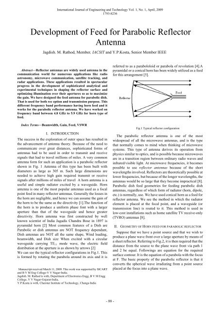
referred to as a parabololoid or parabola <strong>of</strong> revolution [4].A<br />
pyramidal or a conical horn has been widely utilized as a feed<br />
<strong>for</strong> this arrangement [5].<br />
Fig.1 Typical reflector configuration<br />
The parabolic reflector antenna is one <strong>of</strong> the most<br />
widespread <strong>of</strong> all the microwave antennas, and is the type<br />
that normally comes to mind when thinking <strong>of</strong> microwave<br />
systems. This type <strong>of</strong> antenna derives its operation from<br />
physics similar to optics, and is possible because microwaves<br />
are in a transition region between ordinary radio waves and<br />
infrared/visible light. At microwave frequencies, it becomes<br />
possible to use reflector antennas because <strong>of</strong> the short<br />
wavelengths involved. <strong>Reflector</strong>s are theoretically possible at<br />
lower frequencies, but because <strong>of</strong> the longer wavelengths, the<br />
antennas would be so large that they become impractical [8].<br />
<strong>Parabolic</strong> dish feed geometries <strong>for</strong> feeding parabolic dish<br />
antennas, regardless <strong>of</strong> which <strong>for</strong>m <strong>of</strong> radiator (horn, dipole,<br />
etc.) is normally, use. We have used conical horn as a feed <strong>for</strong><br />
reflector antenna. We see the method in which the radiator<br />
element is placed at the focal point, and a waveguide (or<br />
transmission line) is routed to it. This method is used in<br />
low-cost installations such as home satellite TV receive-only<br />
(TVRO) antennas [8].<br />
II. GEOMETRY OF HORN FEED FOR PARABOLIC REFLECTOR<br />
Suppose that we have a point source and that we wish to<br />
produce a plane wave front over a large aperture by means <strong>of</strong><br />
a sheet reflector. Referring to Fig.2, it is then required that the<br />
distance from the source to the plane wave front via path 1<br />
and 2 be equal. Followings are equation <strong>for</strong> the required<br />
surface contour. It is the equation <strong>of</strong> a parabola with the focus<br />
at F. The basic property <strong>of</strong> the parabolic reflector is that it<br />
converts the spherical wave irradiating from a point source<br />
placed at the focus into a plane wave.<br />
- 88 -
International Journal <strong>of</strong> Engineering and Technology Vol. 1, No. 1, April, 2009<br />
1793-8236<br />
Fig. 2 <strong>Parabolic</strong> reflector geometry<br />
2 L = R(1+ cos θ )<br />
(1)<br />
2L<br />
R = (2)<br />
1 + cosθ<br />
Conversely all the energy received by a dish from the<br />
distance source is reflected to a single point at the focus <strong>of</strong> the<br />
disc In Fig.3 parabolic dish parameter is mentioned and the<br />
position <strong>of</strong> the focus or focal length is given by:<br />
design <strong>of</strong> feed if both are to be illuminated efficiently. The<br />
value <strong>of</strong> 0.25 corresponds to the common focal plane dish in<br />
which the focus is in the same plane as the rim <strong>of</strong> the dish.<br />
The lower the f/D ratio, the lower the side lobes, because the<br />
feed is more protected from stray rays. Side lobes can also be<br />
reduced by means <strong>of</strong> additional shielding on the rim <strong>of</strong> the<br />
parabolic reflector (skirt).<br />
A horn antenna can be used to feed the parabolic dish. It is<br />
radiating element which has the shape <strong>of</strong> horn. A horn<br />
antenna may be regarded as a flared out (or opened out)<br />
waveguide. The function <strong>of</strong> the horn is to produce a uni<strong>for</strong>m<br />
phase front with a larger aperture than that <strong>of</strong> the waveguide<br />
and hence greater directivity. A waveguide, when excited at<br />
one end and open at the second end, radiates. However,<br />
radiation is poor and nondirective pattern results because <strong>of</strong><br />
the mismatch between the waveguide and free space. The<br />
mouth <strong>of</strong> the waveguide is flared out to improve the radiation<br />
efficiency, directive pattern and directivity. If in a design <strong>of</strong><br />
horn, the walls <strong>of</strong> a circular waveguide are flared out, a<br />
conical horn is obtained.A conical horn is shown in Fig.4 [5].<br />
Fig.4 Conical horn<br />
Fig. 3 <strong>Parabolic</strong> dish parameter<br />
The size <strong>of</strong> the dish is the most important factor since it<br />
determines the maximum gain that can be achieved at the<br />
given frequency and resulting beam width. The gain and<br />
beam width obtained are given by:<br />
and<br />
( × D) 2<br />
G= π 3<br />
λ<br />
× η<br />
(3)<br />
70λ<br />
BW =<br />
D<br />
(4)<br />
Parameters Given Frequency <strong>of</strong> operation: 4.8 GHz to 5.9<br />
GHz, Diameter <strong>of</strong> the dish (D): 600mm, Focal Length (f):<br />
270 mm, Depth <strong>of</strong> Dish (d): 83 mm, from the parameters<br />
given first calculate f/D ratio. f/D = focal length/Diameter <strong>of</strong><br />
dish = 0.445Actual dish diameter is 600 mm but the diameter<br />
<strong>of</strong> the illuminated area is 432.66 mm (shown as shaded region)<br />
[6]. Horn designed on this basis will somehow reduce the<br />
power radiated outside the region <strong>of</strong> interest effectively<br />
which will cause improvement in gain <strong>of</strong> overall system [7].<br />
Fig.5 is the photograph <strong>of</strong> final <strong>Antenna</strong> prototype known as<br />
a conical horn feed with its connector <strong>for</strong> parabolic reflector<br />
antenna.<br />
Where D =dish diameter<br />
η = efficiency<br />
The efficiency is determined by the effectiveness <strong>of</strong><br />
illumination <strong>of</strong> the dish by the feed, but also by the other<br />
factors. Each time the diameter <strong>of</strong> the dish is doubled, the<br />
gain is four times or 6 dB, greater. If both stations double the<br />
size <strong>of</strong> the dishes, signal strength can be increased <strong>of</strong> 12 dB, a<br />
very substantial gain. An efficiency <strong>of</strong> 50% can be assumed<br />
when hand building the antenna.<br />
The ratio f/D (focal length/diameter <strong>of</strong> dish) is the<br />
fundamental factor governing the design <strong>of</strong> the feed <strong>for</strong> a dish.<br />
The ratio is directly related to the beam width <strong>of</strong> the feed<br />
necessary to illuminate the dish effectively. Two dishes <strong>of</strong> the<br />
same diameter but different focal lengths require different<br />
- 89 -<br />
Fig.5 Horn antenna with connector and feed.<br />
Horn feed designed <strong>for</strong> frequency range <strong>of</strong> (4.8 GHz to 5.9<br />
GHz) is having maximum attainable gain <strong>of</strong> 16 dB (without<br />
reflector) and 32 (dB with reflector). Even it’s observed<br />
Received Gains <strong>for</strong> different feed lengths (Horn with Dish) &<br />
Received Gains <strong>for</strong> different feed lengths (With Horn only)<br />
<strong>Feed</strong> wire length 12mm and feed wire length arrangement<br />
and design <strong>of</strong> horn are very easy and accomplished at a very<br />
low cost.Fig.6 by which we can understand the horn feed
position with respect to disc.<br />
International Journal <strong>of</strong> Engineering and Technology Vol. 1, No. 1, April, 2009<br />
1793-8236<br />
Fig.7.Aperture angle calculations<br />
Fig. 6 Horn feed position with respect to disc<br />
VSWR <strong>for</strong> the antenna is less than 2.5. We have<br />
dimensions are too small that blocking due to feed will be<br />
very low. It’s mounting at 13mm.<br />
Our objective is to design a conical horn feed <strong>for</strong> the<br />
parabolic dish at an operating frequency <strong>of</strong> 5.35 GHz and the<br />
frequency band over which the antenna should work<br />
efficiently is 4.8 to 5.9 GHz<br />
III. DESIGN CALCULATION<br />
Parameters are Frequency <strong>of</strong> operation: 4.8 GHz to 5.9<br />
GHz, Diameter <strong>of</strong> the dish (D): 600mm, Focal Length (f):<br />
270 mm, Depth <strong>of</strong> Dish (d): 83 mm<br />
From the parameters given first calculate f/D ratio.<br />
f<br />
D<br />
=<br />
focal length<br />
Diameter <strong>of</strong> dish<br />
270 mm<br />
= 600 mm<br />
f<br />
= 0.45<br />
D<br />
Circular Waveguide Dimension Calculation: Lower cut <strong>of</strong>f<br />
frequency f c = 4.8 GHz<br />
8<br />
3×<br />
10<br />
∴ λc<br />
=<br />
9<br />
4.8×<br />
10<br />
∴ λ = 62.5 mm<br />
c<br />
Now, circular waveguide can operate in either TE<br />
(Transverse Electric) mode or TM (Transverse Magnetic)<br />
mode. For both mode calculation <strong>of</strong> λ c . Actual dish diameter<br />
is 600 mm but the diameter <strong>of</strong> the illuminated area is 432.66<br />
mm (shown as shaded region). Horn designed on this basis<br />
will somehow reduce the power radiated outside the region <strong>of</strong><br />
interest effectively which will cause improvement in gain <strong>of</strong><br />
overall system.From Fig.7 the value <strong>of</strong> θ can be calculated<br />
from simple trigonometric equation.<br />
−1<br />
⎛BC<br />
⎞<br />
θ = tan ⎜ ⎟<br />
(6)<br />
⎝ AB ⎠<br />
−1 ⎛216.33<br />
⎞<br />
∴ θ = tan ⎜ ⎟<br />
⎝ 187 ⎠<br />
= 49.15 0<br />
(5)<br />
For the ease <strong>of</strong> designing & calculation taking θ ≈ 50º, see<br />
in below Fig.8.<br />
Fig.8.Geometry <strong>for</strong> angle<br />
∴ tan50 =<br />
BC<br />
AB<br />
∴ BC = tan(50 ° ) × AB<br />
∴ BC = 222.85 mm<br />
⎛π<br />
D ⎞<br />
G = ⎜ ⎟<br />
⎝ λ ⎠<br />
If aperture is not uni<strong>for</strong>mly illuminated, illumination<br />
efficiency (η) must be introduced.<br />
⎛π<br />
D<br />
G η a ⎞<br />
= ⎜ ⎟<br />
⎝ λ ⎠<br />
Generally η is <strong>of</strong> the order <strong>of</strong> 60%.<br />
G<br />
2<br />
⎛Da<br />
⎞<br />
= 6 ⎜ ⎟<br />
⎝ λ ⎠<br />
Where, G is the power gain ration, not the decibel power<br />
gain. The beam width <strong>of</strong> an ideal paraboloid uni<strong>for</strong>mly<br />
illuminated is given by,<br />
70λ<br />
BW = (9)<br />
D<br />
70×<br />
0.0625<br />
∴ BW =<br />
0.6<br />
Ideal paraboloid with uni<strong>for</strong>m illumination and no losses is<br />
given BW which is<br />
BW = 7.291 0 IV. RESULTS & DISCUSSIONS<br />
Finally results mentioned are <strong>of</strong> 13mm.Fig.9 is the snap<br />
shot <strong>of</strong> gain from spectrum analyzer.<br />
a<br />
2<br />
2<br />
(7)<br />
(8)<br />
- 90 -
International Journal <strong>of</strong> Engineering and Technology Vol. 1, No. 1, April, 2009<br />
1793-8236<br />
ACKNOWLEDGMENT<br />
The Authors thanks to Principal & H.O.D, Electronics<br />
Department <strong>of</strong> B.V.M.Engg.College,<br />
V.V.Nagar-Gujarat-India <strong>for</strong> their support and<br />
Encouragements, V.V.Nagar and Twin Engineers, Baroda <strong>for</strong><br />
given testing and development facility <strong>for</strong> this work.<br />
Fig. 9 Gain <strong>for</strong> horn antenna with centre frequency <strong>of</strong> 5.35 GHz<br />
<strong>Parabolic</strong> dish antenna is the most commonly and widely<br />
used antenna in communication field mainly in satellite and<br />
radar communication. The feed designs <strong>for</strong> the parabolic<br />
dishes are having their own advantages over conventional<br />
feed. Horn feed designed <strong>for</strong> frequency range <strong>of</strong> (4.8 GHz to<br />
5.9 GHz) is having maximum attainable gain <strong>of</strong> 16 dB<br />
(without reflector) and 32 (dB with reflector). Even its<br />
dimensions are too small that blocking due to feed will be<br />
very low. Its mounting arrangement and design <strong>of</strong> horn are<br />
very easy and accomplished at a very low cost. VSWR <strong>for</strong> the<br />
antenna is less than 2.5.See in Table-1 the different reading<br />
which is measured on spectrum analyzer. This shows how<br />
conical horn feed can improve the per<strong>for</strong>mance <strong>of</strong> parabolic<br />
reflector antenna.<br />
Freq<br />
(GHz)<br />
TABLE 1 OBSERVATION OF FEED AND WITHOT FEED<br />
Received Gains <strong>for</strong> different<br />
feed lengths ( Horn with Dish )<br />
Received Gains <strong>for</strong> different<br />
feed lengths<br />
( With Horn only )<br />
<strong>Feed</strong> wire <strong>Feed</strong> wire<br />
length 12mm length 13mm<br />
Gain<br />
Level<br />
(dB) Level Gain<br />
(dB)<br />
f<br />
<strong>Feed</strong> wire length <strong>Feed</strong> wire length<br />
12mm 13mm<br />
Level<br />
Gain<br />
Gain<br />
Level<br />
(dB)<br />
(dB)<br />
5.1 22 25.75 19 28.75 38 9.75 37 10.75<br />
5.2 17 30.92 17 30.92 35 12.98 34 13.92<br />
5.3 16 32.03 16 32.08 32 16.02 33 15.08<br />
5.35 18 30.17 18 30.17 34 14.17 35 13.17<br />
5.4 19 29.25 18 30.25 34 14.25 36 12.25<br />
5.5 22 26.41 18 30.4 38 10.41 37 11.41<br />
5.6 19 29.56 22 26.56 38 10.56 38 10.56<br />
V. CONCLUSION<br />
A feed is the main point <strong>of</strong> contact between the dish and<br />
the coaxial cable or a wave guide. In short, we can say that a<br />
feed is a medium <strong>of</strong> communication <strong>for</strong> the dish. It means that<br />
by means <strong>of</strong> the feed, we can communicate with the dish, <strong>of</strong><br />
course the communication is bidirectional. We have<br />
enhances the gain by almost double by using horn feed<br />
parabolic reflector antenna then without horn feed parabolic<br />
reflector antenna. Horn feed designed <strong>for</strong> frequency range <strong>of</strong><br />
(4.8 GHz to 5.9 GHz) is having maximum attainable gain <strong>of</strong><br />
16 dB (without reflector) and 32 (dB with reflector).<br />
REFERENCES<br />
[1] Constantine. A. Balanis “<strong>Antenna</strong> Theory: Analysis and Design”<br />
(2nd Ed.)<br />
[2] J.D. Kraus & Ronald J.Marhefka “<strong>Antenna</strong> <strong>for</strong> all applications “ (3rd<br />
Ed.)<br />
[3] M.L.Sisodia and Vijay Laxmi Gupta ‘Microwaves: Introduction to<br />
Circuits, Devices and <strong>Antenna</strong>s” (1st Ed.)<br />
[4] Kennedy Davis “Electronic communication system “ (3rd Ed.)<br />
[5] G.S.N.Raju “<strong>Antenna</strong>s and wave propagation “ (1st Ed.)<br />
[6] Rajeshwari Chatterjee “<strong>Antenna</strong> Theory and Practice” (1st Ed.)<br />
[7] B Paul Wade “Electromagnetic horn antennas“1994, 1998<br />
[8] Joseph J. Carr” Practical <strong>Antenna</strong> Handbook “Fourth Edition<br />
Jagdish M.Rathod He is born in 1972 at<br />
Mumbai-India.He has received his Bachelor <strong>of</strong> Engg<br />
& Master <strong>of</strong> Engg in 1995 & 2005 with respectively in<br />
Electronics & Communication engg.He is working as a<br />
lecturer in B V M Engg College since 1997.He got a<br />
Fourteen years <strong>of</strong> experience as a lecturer. He is<br />
pursuing his PhD since Oct-2006 in Electronics &<br />
Communication from S P University under the kind support <strong>of</strong> Dr.Y.P.Kosta,<br />
CIT, Changa-Gujarat. He is a Life member <strong>of</strong> I.E.T.E & IE (I) & I.S.T.E.,<br />
IACSIT, BES etc <strong>of</strong>ficial organization He has published a Twenty-four<br />
number technical and fundamental research papers in national and<br />
International journals and conferences till this date.<br />
Dr. Yogesh Kosta He has Received his M.Tech & PhD<br />
in Electronics and Telecommunicationin1991 and1998<br />
w.r.t.He than joined I S R O Ahmedabad, where he<br />
designed & developed the Ku –band transponder 3D<br />
Satellites. He also worked as a faculty in United Nation’s<br />
PG Program on SATCOM. He later joined Teledyne<br />
Wireless at Mt.View, Cali<strong>for</strong>nia as a senior design<br />
engineer. He designs MMIC-Power Amplifier Chipsets<br />
<strong>for</strong> commercial and military applications.. He is senior member <strong>of</strong> IETE,<br />
IEEE, and M-TTS.He has published and presented more than a Thirty Five<br />
technical and fundamental research papers in national and International<br />
journals and conferences till this date.<br />
- 91 -