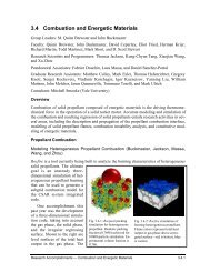
3.2 Combustion and Energetic Materials - Center for Simulation of ...
3.2 Combustion and Energetic Materials - Center for Simulation of ...
3.2 Combustion and Energetic Materials - Center for Simulation of ...

You also want an ePaper? Increase the reach of your titles
YUMPU automatically turns print PDFs into web optimized ePapers that Google loves.
<strong>3.2</strong> <strong>Combustion</strong> <strong>and</strong> <strong>Energetic</strong> <strong>Materials</strong><br />
Group Leader: M. Quinn Brewster<br />
Faculty: Joanna Austin, Quinn Brewster, John Buckmaster, David Ceperley, Gregory Elliott, Nicholas<br />
Glumac, Herman Krier, D. Scott Stewart, <strong>and</strong> Pratap Vanka<br />
Research Scientists <strong>and</strong> Programmers: Thomas Jackson, Kung-Chyun Tang, <strong>and</strong> Xiaojian Wang<br />
Postdoctoral Associate: Changrong Cui, Luca Massa <strong>and</strong> Sunhee Yoo<br />
Graduate Research Assistants: Kelly Aita, Mark Esler, Russell Fitzgerald, Jon Harrison, David Kessler,<br />
Igor Kuznetsov, Jessica Mullen, Matthew Parker, William Ross, Michael Willcox, <strong>and</strong> Lanying Zeng<br />
Overview<br />
<strong>Combustion</strong> <strong>of</strong> solid propellant composed <strong>of</strong> energetic materials is the driving thermomechanical <strong>for</strong>ce in<br />
the operation <strong>of</strong> a solid rocket motor. Accurate modeling <strong>and</strong> simulation <strong>of</strong> the combustion <strong>and</strong> resulting<br />
regression <strong>of</strong> solid propellants entails research activities in several areas, including the description <strong>and</strong><br />
propagation <strong>of</strong> the propellant combustion interface, modeling <strong>of</strong> solid propellant flames, combustion instability<br />
analysis, <strong>and</strong> constitutive modeling <strong>of</strong> energetic materials.<br />
The <strong>Combustion</strong> <strong>and</strong> <strong>Energetic</strong> <strong>Materials</strong> (CEM) group has a hierarchical strategy <strong>for</strong> developing<br />
solid propellant combustion models based on incremental physical/modeling complexity <strong>and</strong> parallel experimental<br />
validation. Under this strategy the daunting complexity <strong>of</strong> composite solid propellant combustion<br />
is attacked by isolating various physical/chemical phenomena within a lowest dimensional model<br />
necessary to address each level. Non-aluminized propellant issues are tackled first <strong>and</strong> then aluminum is<br />
added.<br />
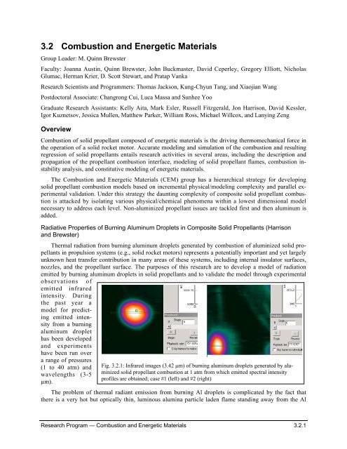
Radiative Properties <strong>of</strong> Burning Aluminum Droplets in Composite Solid Propellants (Harrison<br />
<strong>and</strong> Brewster)<br />
Thermal radiation from burning aluminum droplets generated by combustion <strong>of</strong> aluminized solid propellants<br />
in propulsion systems (e.g., solid rocket motors) represents a potentially important <strong>and</strong> yet largely<br />
unknown heat transfer contribution in many areas <strong>of</strong> these systems, including internal insulator surfaces,<br />
nozzles, <strong>and</strong> the propellant surface. The purposes <strong>of</strong> this research are to develop a model <strong>of</strong> radiation<br />
emitted by burning aluminum droplets in solid propellants <strong>and</strong> to validate the model through experimental<br />
observations <strong>of</strong><br />
emitted infrared<br />
intensity. During<br />
the past year a<br />
model <strong>for</strong> predicting<br />
emitted intensity<br />
from a burning<br />
aluminum droplet<br />
has been developed<br />
<strong>and</strong> experiments<br />
have been run over<br />
a range <strong>of</strong> pressures<br />
(1 to 40 atm) <strong>and</strong><br />
wavelengths (3-5<br />
µm).<br />
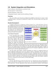
Fig. <strong>3.2</strong>.1: Infrared images (3.42 µm) <strong>of</strong> burning aluminum droplets generated by aluminized<br />
solid propellant combustion at 1 atm from which emitted spectral intensity<br />
pr<strong>of</strong>iles are obtained; case #1 (left) <strong>and</strong> #2 (right)<br />
The problem <strong>of</strong> thermal radiant emission from burning Al droplets is complicated by the fact that<br />
there is a very hot but optically thin, luminous alumina particle laden flame st<strong>and</strong>ing away from the Al<br />
Research Program — <strong>Combustion</strong> <strong>and</strong> <strong>Energetic</strong> <strong>Materials</strong> <strong>3.2</strong>.1
droplet surface. There is the potential <strong>for</strong> substantial emission by this non-isothermal, optically nonhomogeneous,<br />
reaction zone as well as by the Al droplet surface. Furthermore the system’s behavior<br />
could be quite different at different wavelengths; the behavior in the important infrared region could be<br />
quite different than that indicated by typical visible (optical/video) imaging, hence the need <strong>for</strong> infrared<br />
imaging <strong>and</strong> spectrally/spatially resolved modeling. The model developed accounts <strong>for</strong> non-gray emission<br />
by the hot, molten aluminum surface as well as non-gray emission by sub-micron, molten aluminumoxide<br />
particles that populate the non-isothermal, detached, diffusion-flame envelope.<br />
Typical experimental results <strong>for</strong><br />
emitted intensity at 3.42 µm <strong>and</strong> 1<br />
atm are shown in Figure <strong>3.2</strong>.1. The<br />
thin rectangle at the center <strong>of</strong> the<br />
droplet image indicates the region<br />
from which the indicated intensity<br />
pr<strong>of</strong>ile was taken. Intensity is seen to<br />
peak near the center <strong>of</strong> the droplet. In<br />
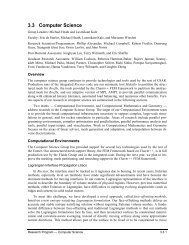
Figure <strong>3.2</strong>.2, a comparison between<br />
modeled <strong>and</strong> experimental intensity<br />
is shown <strong>for</strong> these conditions. The<br />
intensity is plotted as the ratio <strong>of</strong> the<br />
burning aluminum droplet intensity<br />
to the intensity <strong>of</strong> a hot nichrome<br />
ribbon used <strong>for</strong> calibration. The<br />
model curve with the short dashed<br />
line (“model – with smoke envelope”)<br />
shows the prediction based on<br />
best guesses about optical <strong>and</strong> thermal<br />
properties <strong>of</strong> the aluminum<br />
droplet <strong>and</strong> the oxide-laden flame<br />
Droplet/Nichrome Intensity Ratio<br />
1.5<br />
1<br />
0.5<br />
Large Smoke<br />
Envelope Intensity<br />
Does Not Exist in<br />
Experiments<br />
Intensity Ratio at 3.42 micron <strong>and</strong> 1 atm<br />
0<br />
-600 -500 -400 -300 -200 -100 0 100 200 300 400 500 600<br />
Position (micron)<br />
envelope region. Without adjustments the agreement is reasonable. For comparison, two limiting model<br />
predictions are also shown, one with the flame (smoke) envelope removed <strong>and</strong> one with the flame envelope<br />
made artificially optically thick. For optically thin smoke/flame conditions there is a predicted secondary<br />
maximum away from the center <strong>of</strong> the droplet at the location <strong>of</strong> the detached diffusion flame. No<br />
prominent intensity is observed experimentally, however, in this region. This is in contrast to video (primarily<br />
visible very near infrared) imaging. The results <strong>of</strong> model <strong>and</strong> experiment thus suggest that in the<br />
infrared region (unlike the visible region) the flame envelope emission contribution is negligible <strong>and</strong> the<br />
aluminum emission contribution dominates. Further experiments <strong>and</strong> modeling are being conducted to<br />
verify these findings <strong>and</strong> to explore the effects <strong>of</strong> pressure <strong>and</strong> other variables.<br />
Aluminum Effects in <strong>Combustion</strong> <strong>of</strong> Composite Solid Propellants (Mullen <strong>and</strong> Brewster)<br />
The effects <strong>of</strong> combustion <strong>of</strong> non-metalized oxidizer/fuel constituents Ammonium Perchlorate-<br />
Hydroxy-Terminated Polybutadiene (AP/HTPB) on aluminum agglomeration, ignition, <strong>and</strong> combustion<br />
in aluminized composite solid propellants are not well know. Neither are the effects <strong>of</strong> aluminum combustion<br />
on AP/HTPB behavior, although it has widely been thought that aluminum does not affect<br />
Al/HTPB combustion significantly since global (macroscopically averaged) burning rate does not seem<br />
much affected. Better underst<strong>and</strong>ing <strong>of</strong> the fundamental combustion <strong>of</strong> three-dimensional aluminized APcomposite<br />
solid propellants is needed <strong>and</strong> can be gained through investigating the behavior <strong>of</strong> aluminized<br />
laminate configurations. Laminate propellants allow <strong>for</strong> a more controlled study <strong>of</strong> the effects <strong>of</strong><br />
AP/HTPB oxidizer-fuel components on the ignition, agglomeration, <strong>and</strong> combustion <strong>of</strong> aluminum as well<br />
as the inverse effects.<br />
Expt Pr<strong>of</strong>ile 1<br />
Expt Pr<strong>of</strong>ile 2<br />
Model - No Smoke Envelope<br />
Model - With Smoke Envelope<br />
Model = Thick Hypothetical Smoke<br />
Fig. <strong>3.2</strong>.2: Comparison <strong>of</strong> experimental results <strong>and</strong> model predictions<br />
<strong>of</strong> emitted intensity at 3.42 µm (1 atm) from burning aluminum<br />
droplets as a function <strong>of</strong> radial position showing dominance <strong>of</strong><br />
emission by molten aluminum.<br />
Research Program — <strong>Combustion</strong> <strong>and</strong> <strong>Energetic</strong> <strong>Materials</strong> <strong>3.2</strong>.2
AP<br />
Fine-AP/HTPB<br />
AP<br />
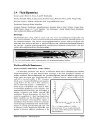
Fig. <strong>3.2</strong>.3: Laminates showing contrasting surface features in fuel layer at 15 atm. (left) Fuel layer consisting<br />
<strong>of</strong> 76/24 fine-AP/HTPB without Al showing protruding fuel surface <strong>and</strong> (right) fuel layer consisting <strong>of</strong><br />
same fuel-rich matrix with Al (31%) showing flat (non-protruding) surface in fuel region.<br />
The two primary variables thought to affect aluminum agglomeration <strong>and</strong> ignition are the size or<br />
length-scale <strong>of</strong> the fuel-rich “pocket” between coarse AP particles <strong>and</strong> the pressure. Both <strong>of</strong> these variables<br />
are known to have a dominant influence in determining the AP/binder flame structure (i.e., whether<br />
the flame is split-diffusion or merged-premixed). The <strong>for</strong>mer (length scale) also influences the amount <strong>of</strong><br />
aluminum in close spatial proximity available to agglomerate. Previous research in our group investigated<br />
AP/HTPB flame structure in non-aluminized laminate propellants <strong>and</strong> showed the effects <strong>of</strong> pressure <strong>and</strong><br />
length scale (center fuel-layer thickess); Figure <strong>3.2</strong>.3 shows a typical image (left) <strong>for</strong> conditions <strong>of</strong> 15 atm<br />
<strong>and</strong> 1000-µm fuel layer where the AP/HTPB flames are split <strong>and</strong> located near the AP/HTPB interfaces.<br />
As a result the fuel layer surface protrudes sharply upward. (At low pressures <strong>and</strong> small length-scales the<br />
flame structure tends toward merged-premixed.)<br />
New results obtained during the past year with aluminized laminates has produced surprising results.<br />
Conventional models <strong>and</strong> underst<strong>and</strong>ing would suggest that addition <strong>of</strong> aluminum has little effect on<br />
AP/HTPB flame structure <strong>and</strong> burning surface structure. Recent results seem to indicate that at least part<br />
<strong>of</strong> that underst<strong>and</strong>ing may be incorrect. Figure <strong>3.2</strong>.3 (right) shows an image with aluminum added. While<br />
the primary, coarse-AP/HTPB flame structure appears to still be split (diffusion), as evidenced by the location<br />
<strong>of</strong> Al droplet ignition, the fine-AP/HTPB surface pr<strong>of</strong>ile is not protruding but flat. Thus laminate<br />
propellants show that simply adding Al has a pr<strong>of</strong>ound affect on combustion <strong>of</strong> the fine-AP/HTPB flame<br />
zone over the fuel-rich zone. These observations provide data <strong>for</strong> further refinement <strong>of</strong> heterogeneous<br />
propellant combustion models <strong>and</strong> simulations <strong>of</strong> aluminized propellants.<br />
Multiscale Modeling <strong>of</strong> Solid Rocket Motors: 2-D Quasi-steady Burning Using Parallel Multigrid<br />
Algorithm (Stewart <strong>and</strong> Bhattacharjee)<br />
A multigrid acceleration technique with time integration is being implemented <strong>for</strong> the problem <strong>of</strong> efficiently<br />
computing the stable burn-back <strong>of</strong> a 2-D solid rocket motor when the motor is in the quasisteady<br />
burning regime <strong>of</strong> operation. For large rockets such as the space shuttle solid rocket booster, the<br />
problem <strong>of</strong> quasi-steady solid rocket motor core flow is analogous to the steady aerodynamic flow past a<br />
large aircraft flying at speeds such that compressible flow effects must be included. The time integration<br />
strategies that have been developed <strong>for</strong> such applications are used to simulate solid rocket motor grain<br />
burning <strong>and</strong> to compute a series <strong>of</strong> realizations <strong>of</strong> steady flows as the grain burns back to near completion<br />
Research Program — <strong>Combustion</strong> <strong>and</strong> <strong>Energetic</strong> <strong>Materials</strong> <strong>3.2</strong>.3
y a slow regression <strong>of</strong> the burning solid<br />
propellant. A straight<strong>for</strong>ward two-timing,<br />
multiscale asymptotic analysis <strong>of</strong> the quasisteady<br />
rocket burn developed in a previous<br />
paper will be used to advance the propellant<br />
interface from steady states with frozen geometry.<br />
Preliminary computations show<br />
speedups on a serial processor <strong>of</strong> 4 to 5<br />
times that over a direct Euler solver <strong>for</strong> the<br />
same two axisymmetric geometry. Work is<br />
currently under way to implement the algorithm<br />
on parallel processors using domain<br />
decomposition. We anticipate speed ups<br />
that scale linearly with the number <strong>of</strong> processors,<br />
such that 256 processors (say) <strong>of</strong>fers<br />
a possible speed up <strong>of</strong> 1000 times (at a fixed<br />
spatial resolution) to achieve a steady frozen<br />
configuration that is to be advanced by<br />
the surface regression algorithm (Figures<br />
<strong>3.2</strong>.4 <strong>and</strong> <strong>3.2</strong>.5).<br />
Shock Initiation via Void Collapse<br />
(Parker <strong>and</strong> Austin)<br />
The <strong>for</strong>mation <strong>of</strong> local regions <strong>of</strong> energy<br />
release or hot spots is critical to detonation<br />
initiation in heterogeneous energetic<br />
materials. Hot spots are <strong>for</strong>med due to<br />
shock interaction with material heterogeneities,<br />
including voids in <strong>and</strong> between explosive<br />
crystals. We study the fundamental<br />
mechanisms <strong>of</strong> shock-void interaction relevant<br />
to condensed phase detonation initiation<br />
in a simplified system with dynamic,<br />
spatially resolved experimentation.<br />
Fig. <strong>3.2</strong>.4: Instantaneous flowfields, <strong>for</strong> (from top down)<br />
Mach number, pressure, density, <strong>and</strong> x <strong>and</strong> y velocity components,<br />
<strong>for</strong> three different times computed with high order<br />
Euler solver, with resolution <strong>of</strong> (560 x 40).<br />
A layer <strong>of</strong> gelatinous material containing one or more voids is s<strong>and</strong>wiched between two optically accessible<br />
plates. A 152mm diameter aluminum bullet is accelerated by a gas gun <strong>and</strong> impacts the test mate-<br />
Fig. <strong>3.2</strong>.5: Steady state Euler solution <strong>for</strong> coarsest grid (140x10) <strong>and</strong> intermediate grid (280 x 20).<br />
Research Program — <strong>Combustion</strong> <strong>and</strong> <strong>Energetic</strong> <strong>Materials</strong> <strong>3.2</strong>.4
ial, transmitting a shock wave with velocity<br />
1850 m/s <strong>and</strong> post-shock pressure <strong>of</strong> 0.25Gpa<br />
(Figure <strong>3.2</strong>.6). A high speed camera capable <strong>of</strong><br />
80 frames with a 1 microsecond interframe time<br />
is used to track the shock. The illumination <strong>for</strong><br />
the experiment is provided by a 2w 514nm diode<br />
laser pulsed by passing the light through an<br />
acousto-optic modulator.<br />
Initially, static compression testing was used<br />
to identify appropriate material properties <strong>and</strong><br />
yielded encouraging results. Recently, high<br />
speed shadowgraph movies tracking the shock<br />
propagation through the gel have been made.<br />
The newly acquired diode laser has solved illumination<br />
problems that were limiting the resolution<br />
<strong>of</strong> the images.<br />
Three-Dimensional Propellant <strong>Combustion</strong><br />
<strong>Simulation</strong> (Buckmaster, Jackson, Massa,<br />
Wang)<br />
Fig. <strong>3.2</strong>.6: Experimental setup showing gas gun, test<br />
section <strong>and</strong> high speed camera.<br />
The research group <strong>of</strong> Jackson, Buckmaster, Massa <strong>and</strong> Wang has been engaged <strong>for</strong> a number <strong>of</strong><br />
years in the numerical simulation <strong>of</strong> three-dimensional heterogeneous solid propellant combustion. To<br />
this end we have, <strong>for</strong> the first time, created a three-dimensional code that fully couples the propellant<br />
solid physics with the gas-phase combustion in a non-planar non-steadily regressing propellant surface.<br />
We have validated burning rate predictions <strong>and</strong> the variations <strong>of</strong> these rates with propellant morphology<br />
by comparisons with experiment, without the use <strong>of</strong> curve fitting with three-dimensional results. We<br />
have, <strong>for</strong> the first time, been able to examine numerically the impact <strong>of</strong> acoustic waves on a burning heterogeneous<br />
propellant, <strong>and</strong> describe the properties <strong>of</strong> the reflected wave, a crucial issue in rocket chamber<br />
stability. Furthermore, we have, <strong>for</strong> the first time, been able to describe the proper injection boundary<br />
conditions <strong>for</strong> LES simulations, necessary <strong>for</strong> meaningful solid rocket motor simulations. For aluminized<br />
propellants we have developed algorithms that accurately predict the statistics <strong>of</strong> the aluminum agglomerates<br />
that <strong>for</strong>m on the surface <strong>and</strong> which, after detachment, are <strong>of</strong> great concern to the rocket industry because<br />
<strong>of</strong> their impact on the nozzle. Aluminum agglomeration in the throat seriously degrades the specific<br />
impulse <strong>of</strong> the motor <strong>and</strong> significantly shortens the operational range <strong>of</strong> a motor. Hence this work has an<br />
enormous potential in that by tailoring the characteristics <strong>of</strong> the propellant packs to minimize aluminum<br />
agglomeration, one may be able to extend operating range <strong>of</strong> Air Force strategic missiles. A number <strong>of</strong><br />
important projects have been worked on in the previous year, <strong>and</strong> are summarized below. These projects<br />
include the completion or modification <strong>of</strong> previous work, as well as the beginnings <strong>of</strong> new projects.<br />
P1. Rational Rocburn We have developed what we call Rational_Rocburn, a Rocburn module that is<br />
constructed by spatial averaging <strong>of</strong> Rocfire, accounting <strong>for</strong> unsteady effects on the propellant time scale.<br />
A key component <strong>of</strong> this module is a look-up table that properly accounts <strong>for</strong> the heat flux to the propellant<br />
surface from the Rocfire combustion field. This module has been incorporated into Rocstar <strong>and</strong> the<br />
central goal <strong>of</strong> the CEM group has now been achieved, albeit <strong>for</strong> non-aluminized propellants. Last year<br />
we published results <strong>for</strong> two-dimensional packs. We are currently extending the analysis to threedimensional<br />
packs.<br />
P2. Rocpack In order to simulate the combustion <strong>of</strong> three-dimensional composite propellants, a representation<br />
<strong>of</strong> the solid is required. To this end we previously developed Rocpack, a dynamic packing algorithm<br />
that takes as input industrial data size distributions, <strong>and</strong> generates a representative “virtual” solid<br />
propellant with the same volume fraction as that used in industry. The original version <strong>of</strong> the code only<br />
Research Program — <strong>Combustion</strong> <strong>and</strong> <strong>Energetic</strong> <strong>Materials</strong> <strong>3.2</strong>.5
packed AP particles, <strong>and</strong> was not user friendly. We there<strong>for</strong>e extended the code this past fiscal year to<br />
include a number <strong>of</strong> important features.<br />
The particles can now be AP, HMX, RDX, aluminum, etc., or a combination, embedded in a binder,<br />
usually taken to be HTPB. The current version <strong>of</strong> the code is written in Fortran 90 <strong>and</strong> uses MPI. It has a<br />
user-friendly interface so that non-technical people can use the code. This new interface is called Rocprepack.<br />
Rocprepack <strong>and</strong> Rocpack are both in a CVS directory <strong>for</strong> others to download.<br />
In the mixing<br />
process <strong>of</strong> real<br />
propellants, large<br />
AP particles are<br />
mixed first so that<br />
the binder coats<br />
each AP particle;<br />
smaller AP particles<br />
are then<br />
poured into this<br />
mixture. This generates<br />
a pack<br />
where the binder<br />
separates the large<br />
AP particles. To<br />
better simulate this<br />
Fig. <strong>3.2</strong>.7. Left: R<strong>and</strong>om pack <strong>of</strong> spheres representing a tri-modal AP propellant. <strong>Center</strong>:<br />
Multi-modal pack <strong>of</strong> ellipsoids. Right: Two-dimensional pack <strong>of</strong> rectangles.<br />
process, we have added a “coating” parameter to Rocpack, which allows the user to define an averaged<br />
separation distance <strong>for</strong> all particles. A typical coating value might be 190 nm.<br />
Typical packs range in size from as few as 30,000 particles, which can be generated on 16-processors<br />
in about one day, up to 500,000 particles, which requires 100- processors <strong>and</strong> takes approximately 36 wall<br />
clock hours to generate. Both ATK <strong>and</strong> Aerojet West have expressed interest in using this code in their<br />
Air Force sponsored research, <strong>and</strong> it is our intent to license the code to them. In the coming fiscal year we<br />
plan to make Rocprepack a GUI driven interface.<br />
In addition to the modifications listed above, the inclusion <strong>of</strong> non-spherical particles, in particular ellipsoids,<br />
was added as a new feature. The capability to model non-spherical particles was added to study<br />
the effect <strong>of</strong> particle shape on burn rates. <strong>Combustion</strong> results using Rocfire show that if the ellipsoids are<br />
r<strong>and</strong>omly oriented, then the average burn rate differs little from their spherical counterparts. However, if<br />
the ellipsoids are aligned in some preferred direction, then the average burn rate can be changed significantly.<br />
This might have practical implications in motor design, but we plan no further modifications unless<br />
asked by the rocket industry.<br />
Finally, we are looking into extending Rocpack to include arbitrary shapes. We recently added the capability<br />
<strong>of</strong> packing rectangles, necessary as a first step in simulation igniters. More general shapes will be<br />
added in the coming year.<br />
P3. Rocfire – Non-aluminized Once the “virtual” propellants have been built, they need to be “virtually<br />
burned”. To this end we have previously developed Rocfire: in the gas phase this solves the threedimensional<br />
zero Mach number equations <strong>for</strong> a reacting gas, <strong>and</strong> in the solid phase solves the threedimensional<br />
unsteady heat equation. The solid <strong>and</strong> gas are closely coupled using appropriate jump conditions<br />
<strong>and</strong> pyrolysis laws across their interface, which is represented using level sets, hereby allowing the<br />
surface to take on any shape the physics dictates. The code is written in Fortran 90 <strong>and</strong> uses MPI, <strong>and</strong><br />
uses GMRES to speed up the pressure solver. Typical grid sizes are approximately 1-10 microns, while<br />
the packs are on the size <strong>of</strong> 1-2 millimeters. A typical output <strong>of</strong> Rocfire is shown in Figure <strong>3.2</strong>.8. Our experience<br />
is that this size is sufficient <strong>for</strong> purposes <strong>of</strong> gathering statistics. To get the necessary statistics,<br />
Research Program — <strong>Combustion</strong> <strong>and</strong> <strong>Energetic</strong> <strong>Materials</strong> <strong>3.2</strong>.6
typical run time is approximately 2-3 days using 100 processors<br />
<strong>for</strong> a fixed pressure. To get a complete pressure history, the code<br />
needs to run <strong>for</strong> several weeks given dedicated computer time. A<br />
variation <strong>of</strong> Rocfire (non-aluminized) has been developed using<br />
a three-step kinetics model rather than a two-step model as in<br />
the first implementation. Superior agreement with experimental<br />
burning rates <strong>of</strong> various Miller packs is achieved <strong>and</strong> further<br />
improvement in this respect cannot be expected. The new model<br />
leads to intrinsic instabilities under some circumstances, the stability<br />
boundaries <strong>of</strong> which cannot be expected to match reality,<br />
but there might be no resolution <strong>of</strong> this difficulty within the<br />
framework <strong>of</strong> global kinetics. We hope to revisit this difficulty<br />
in the coming fiscal year using the newly developed code Rocfit,<br />
as described below.<br />
P4. Acoustics Rocfire has been applied to an important<br />
physical problem, namely the burning response to an impinging<br />
acoustic wave. There are serious rocket stability issues should<br />
the reflected wave have a larger amplitude than the incident wave. We have been able to compare the<br />
mass-flux response function <strong>and</strong> the velocity response function (both functions <strong>of</strong> frequency) <strong>and</strong> have<br />
shown to what extent they differ. Since the velocity response cannot be measure experimentally, whereas<br />
the mass-flux response can, it is always assumed that they are equal in making stability predictions, <strong>and</strong><br />
we have described the errors that can arise in doing this. The original work was <strong>for</strong> two-dimensional<br />
packs, but we hope to revisit the problem in three-dimensions within the coming fiscal year.<br />
P5. Rocfit The use <strong>of</strong> detailed kinetic schemes is still too computationally intensive <strong>for</strong> threedimensional<br />
simulations so global kinetic schemes are employed instead. However, global kinetic<br />
schemes involve a number <strong>of</strong> parameters that must be chosen in a rational way. To this end we have recently<br />
developed Rocfit, a numerical s<strong>of</strong>tware tool that uses a numerical optimization scheme based on<br />
genetic algorithms to choose optimal parameters. Rocfit runs on an MPI plat<strong>for</strong>m using 100-processors,<br />
<strong>and</strong> takes about 12 hours to generate a set <strong>of</strong> parameters. Rocfit is currently being used to calibrate the<br />
global kinetic parameters <strong>for</strong> HMX/HTPB propellants <strong>for</strong> which extensive experimental data are available.<br />
Figure <strong>3.2</strong>.9 shows an instantaneous surface temperature pr<strong>of</strong>ile <strong>for</strong> one HMX propellant pack. In<br />
the near future we will use Rocfit to re-calibrate the AP/HTPB kinetic parameters, <strong>and</strong> compare burn rate<br />
results with previous work. It is expected that by using Rocfit, the intrinsic instability mentioned earlier<br />
when using h<strong>and</strong> optimization, can be avoided.<br />
P6. Far-field Solutions The CSAR code Rocstar<br />
accommodates turbulence using large-eddy simulations.<br />
Here a new challenge, not present in traditional<br />
scenarios, is a proper accounting <strong>of</strong> the nature <strong>of</strong> the<br />
injected flow at the chamber/propellant boundary.<br />
Particularly <strong>for</strong> heterogeneous propellants, this flow<br />
<strong>and</strong> the vorticity it carries is neither steady nor spatially<br />
uni<strong>for</strong>m. These fluctuations could well have an<br />
effect on the overall chamber flow <strong>and</strong>, indeed, there<br />
is a significant amount <strong>of</strong> experimental <strong>and</strong> computational<br />
work that demonstrates the effect <strong>of</strong> perturbations<br />
<strong>of</strong> initial or boundary conditions on the longtime<br />
or far-field solution <strong>of</strong> turbulent flow-fields. Of<br />
particular interest in rocket flows is the interaction<br />
between the omnipresent acoustic waves <strong>and</strong> fluctua-<br />
Fig. <strong>3.2</strong>.8: Total heat output at an<br />
instant <strong>of</strong> time <strong>for</strong> AP/HTPB propellant.<br />
The pack morphology is<br />
also shown.<br />
Fig. <strong>3.2</strong>.9. Instantaneous surface temperature<br />
<strong>and</strong> pack morphology <strong>for</strong><br />
HMX/HTPB propellant.<br />
Research Program — <strong>Combustion</strong> <strong>and</strong> <strong>Energetic</strong> <strong>Materials</strong> <strong>3.2</strong>.7
Fig. <strong>3.2</strong>.10. Left: Instantaneous velocity contours (33% fluctuations) as function <strong>of</strong> normal distance<br />
above propellant surface; similar contours are obtained <strong>for</strong> temperature field (14% fluctuations about<br />
mean). Right: Head-end pressure as function <strong>of</strong> time <strong>for</strong> four different mass flux input distributions.<br />
tions <strong>of</strong> the injected flow, <strong>and</strong> a number <strong>of</strong> studies have shown how important this can be <strong>for</strong> certain parameter<br />
values. For these reasons alone, notwithst<strong>and</strong>ing the significance <strong>of</strong> any findings, it is <strong>of</strong> interest<br />
to describe the nature <strong>of</strong> the flow-field at an intermediate distance above the propellant surface, intermediate<br />
in the sense that the distance is large compared to the scale <strong>of</strong> the flame structure, but small compared<br />
to appropriately defined flow scales. To this end the far-field <strong>of</strong> Rocfire (~ 1mm from the surface)<br />
is currently being examined <strong>for</strong> very large packs in an attempt to characterize the flow field fluctuations<br />
that should be used as boundary conditions <strong>for</strong> the LES simulations <strong>of</strong> the Fluids Group. Preliminary<br />
work has been carried out <strong>and</strong> implemented into Rocstar.<br />
Figure <strong>3.2</strong>.10 shows the most recent work. The combustion field beyond the flame zone has large<br />
velocity <strong>and</strong> temperature fluctuations (Figure <strong>3.2</strong>.10, left panel), these fluctuations can influence the head<br />
end pressure (see Figure <strong>3.2</strong>.10, right panel). We note that different propellant morphologies yield different<br />
head end pressure fluctuations, an observation impossible with traditional treatment <strong>of</strong> the propellant<br />
surface. We will continue this work in the coming fiscal year. This work is done in collaboration with F.<br />
Najjar.<br />
P7. Rocfire – Aluminized The Rocfire version <strong>of</strong> the code described previously does not take into account<br />
aluminum.<br />
Since almost all<br />
solid propellants <strong>of</strong><br />
interest contain<br />
some amount <strong>of</strong><br />
aluminum, the<br />
code is being extended<br />
to include<br />
the necessary particle<br />
tracking <strong>and</strong><br />
physics modules.<br />
The propellant<br />
surface <strong>and</strong> aluminum<br />
particles in<br />
the gas phase are<br />
tracked using level<br />
sets. Although the<br />
Fig. <strong>3.2</strong>.11. Surface topography <strong>and</strong> temperature level-surfaces <strong>for</strong> sample<br />
propellant at instant <strong>of</strong> time (left) <strong>and</strong> 1.3 ms later (right).<br />
Research Program — <strong>Combustion</strong> <strong>and</strong> <strong>Energetic</strong> <strong>Materials</strong> <strong>3.2</strong>.8
code is not complete, benchmark studies indicate that it will take several weeks on 100 processors <strong>for</strong> a<br />
single successful run. Figure <strong>3.2</strong>.11 shows the instantaneous temperature surface field <strong>for</strong> a threedimensional<br />
pack. The aluminum particles are obvious, <strong>and</strong> are colored according to the temperature field<br />
it locally sees. This project is an enormous one, <strong>and</strong> because <strong>of</strong> its significance to the rocket industry, will<br />
be continued in the coming fiscal year.<br />
P8. Agglomeration Modeling Here we discuss recent work on aluminum agglomeration, an important<br />
subject currently under investigation by both ATK <strong>and</strong> Aerojet. Typical solid rocket motor propellants,<br />
such as those used in the space shuttle boosters, are composed <strong>of</strong> ammonium perchlorate (AP) <strong>and</strong> aluminum<br />
(Al) particles embedded in fuel binder. A typical composition, by weight, is 71% AP, 18% Al, <strong>and</strong><br />
11% binder. The aluminum reacts exothermically with H 2 O <strong>and</strong> CO 2 in the chamber, increasing the specific<br />
impulse by approximately 10%. It also provides efficient damping <strong>of</strong> chamber instabilities, a desirable<br />
effect. However, there are undesirable effects such as slag accumulation, nozzle erosion, <strong>and</strong> significant<br />
exhaust signatures. Because <strong>of</strong> these, aluminum behavior is one <strong>of</strong> the most important problems<br />
faced by the solid propellant industry. An essential feature is agglomeration <strong>of</strong> particles at the propellant<br />
surface. To this end we have developed an agglomeration model, based on Rocpack (see Figure <strong>3.2</strong>.12,<br />
left panel), which yields both the agglomeration diameter <strong>and</strong> the agglomeration distribution (Figure<br />
<strong>3.2</strong>.12, right panel), which are critical <strong>for</strong> meaningful simulations <strong>of</strong> nozzle <strong>and</strong> plume flows. The agglomeration<br />
model has recently been applied to a number <strong>of</strong> IHPRPT propellants developed at Aerojet<br />
West, <strong>and</strong> the results are extremely encouraging (Figure <strong>3.2</strong>.12, right panel). The funding <strong>for</strong> Aerojet<br />
comes from the propulsion group at Edwards Air Force Base AFRL/PRS. We plan to further improve the<br />
agglomeration model in the coming fiscal year, <strong>and</strong> apply it all the data we can obtain from Aerojet <strong>and</strong><br />
ATK Thiokol.<br />
Fig. <strong>3.2</strong>.12. Left: Three-dimensional propellant generated from Rocpack. AP<br />
particles are shown in gray, aluminum particles are shown in copper. Right:<br />
Results from agglomeration model comparing particle distribution from experiments<br />
(blue, Aerojet) with that <strong>of</strong> CSAR model (green). Agreement between<br />
the model <strong>and</strong> the experiments is excellent.<br />
Project Plans A number<br />
<strong>of</strong> combustion projects<br />
critical to the overall success<br />
<strong>of</strong> Rocstar as a predictive<br />
tool <strong>for</strong> solid rocket<br />
motor simulations will<br />
continue in the coming<br />
fiscal year. The integration<br />
<strong>of</strong> Rational_Rocburn into<br />
Rocstar has recently been<br />
completed, <strong>and</strong> attempts<br />
will be made to develop a<br />
similar module <strong>for</strong> threedimensional<br />
packs <strong>and</strong> <strong>for</strong><br />
aluminized propellants.<br />
Rocpack is essentially<br />
complete, although we will<br />
build a GUI <strong>for</strong> the interface<br />
package Rocprepack. Modifications to Rocpack to include the packing <strong>of</strong> three-dimensional elliptic<br />
cylinders might be considered if enough interest exists. The development <strong>of</strong> Rocfit is complete, <strong>and</strong> the<br />
coming fiscal year will see this important tool being applied to AP/HTPB propellants as well as more<br />
modern propellants <strong>of</strong> interest. Acoustics is an important problem, <strong>and</strong> if time allows we hope to revisit<br />
this problem <strong>for</strong> a more in-depth analysis, <strong>and</strong> to make it a module <strong>of</strong> Rocstar. The work on proper injection<br />
boundary conditions <strong>for</strong> meaningful LES simulations will continue to be an important problem. A<br />
module <strong>for</strong> stochastic injection boundary conditions was incorporated into Rocstar last fiscal year, <strong>and</strong> we<br />
expect further improvements in the coming fiscal year. Work on aluminized Rocfire will continue, the<br />
goal there being a fully functional three-dimensional version. We believe that one <strong>of</strong> the most important<br />
contributions that can be made here is to the agglomeration problem, one <strong>of</strong> enormous interest to the US<br />
Research Program — <strong>Combustion</strong> <strong>and</strong> <strong>Energetic</strong> <strong>Materials</strong> <strong>3.2</strong>.9
industry <strong>and</strong> <strong>of</strong> at least equal value to any Rocstar application. We are also examining the role <strong>of</strong> Alex<br />
(nanometer scale aluminum) in the combustion process, as there is considerable interest in this in the industry.<br />
The aluminum work <strong>and</strong> related issues (such as melt layers) could easily extend to the end <strong>of</strong> the<br />
current contract period, but we expect that interim results within the next year framework will be <strong>of</strong> fundamental<br />
value to the integrated code.<br />
Research Program — <strong>Combustion</strong> <strong>and</strong> <strong>Energetic</strong> <strong>Materials</strong> <strong>3.2</strong>.10