750-337; CANopen - MarInfo
750-337; CANopen - MarInfo
750-337; CANopen - MarInfo

You also want an ePaper? Increase the reach of your titles
YUMPU automatically turns print PDFs into web optimized ePapers that Google loves.
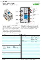
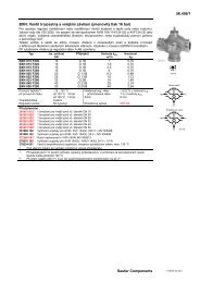
<strong>750</strong>-<strong>337</strong><br />
<strong>CANopen</strong> Fieldbus Coupler<br />
10 kbaud ... 1 Mbaud; digital and analog signals<br />
Fieldbus<br />
conection<br />
Series 231 (MCS)<br />
<strong>CANopen</strong><br />
STOP<br />
RUN<br />
TX<br />
OVERFLOW<br />
RX<br />
I/O<br />
A<br />
B<br />
01 02<br />
24V 0V<br />
+ +<br />
C<br />
D<br />
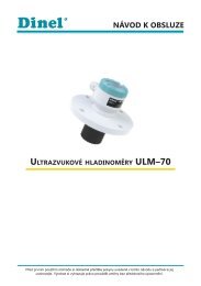
Status<br />
voltage supply<br />
-System<br />
-Power jumper contacts<br />
Data contacts<br />
Supply<br />
24 V<br />
0 V<br />
Supply via<br />
power jumper contacts<br />
24 V<br />
DIP switch<br />
for node ID<br />
and baud rate<br />
1 2 3 4 5 6 7 8<br />
ON<br />
<strong>750</strong>- <strong>337</strong><br />
— —<br />
0 V<br />
Configuration<br />
interface<br />
Power jumper contacts<br />
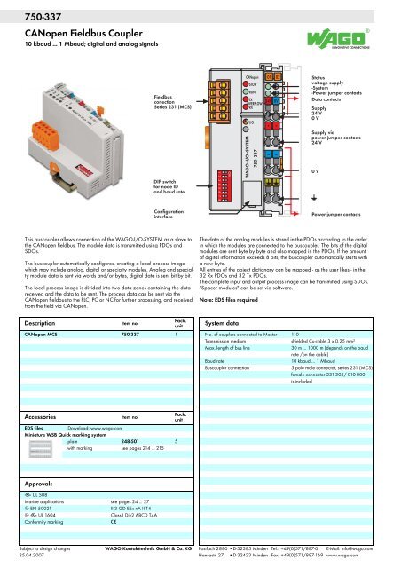
This buscoupler allows connection of the WAGO-I/O-SYSTEM as a slave to<br />
the <strong>CANopen</strong> fieldbus. The module data is transmitted using PDOs and<br />
SDOs.<br />
The buscoupler automatically configures, creating a local process image<br />
which may include analog, digital or specialty modules. Analog and specialty<br />
module data is sent via words and/or bytes, digital data is sent bit by bit.<br />
The local process image is divided into two data zones containing the data<br />
received and the data to be sent. The process data can be sent via the<br />
<strong>CANopen</strong> fieldbus to the PLC, PC or NC for further processing, and received<br />
from the field via <strong>CANopen</strong>.<br />
Pack.<br />
Description<br />
Item no.<br />
unit<br />
<strong>CANopen</strong> MCS <strong>750</strong>-<strong>337</strong> 1<br />
The data of the analog modules is stored in the PDOs according to the order<br />
in which the modules are connected to the buscoupler. The bits of the digital<br />
modules are sent byte by byte and also mapped in the PDOs. If the amount<br />
of digital information exceeds 8 bits, the buscoupler automatically starts with<br />
a new byte.<br />
All entries of the object dictionary can be mapped - as the user likes - in the<br />
32 Rx PDOs and 32 Tx PDOs.<br />
The complete input and output process image can be transmitted using SDOs.<br />
"Spacer modules" can be set via software.<br />
Note: EDS files required<br />
System data<br />
No. of couplers connected to Master 110<br />
Transmission medium<br />
shielded Cu-cable 3 x 0.25 mm²<br />
Max. length of bus line<br />
30 m ... 1000 m (depends on the baud<br />
rate /on the cable)<br />
Baud rate<br />
10 kbaud ... 1 Mbaud<br />
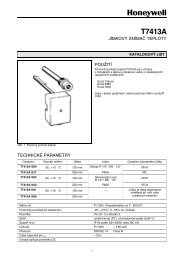
Buscoupler connection<br />
5 pole male connector, series 231 (MCS)<br />
female connector 231-305/ 010-000<br />
is included<br />
Pack.<br />
Accessories<br />
Item no.<br />
unit<br />
EDS files Download: www.wago.com<br />
Miniature WSB Quick marking system<br />
plain 248-501 5<br />
with marking see pages 214 ... 215<br />
Approvals<br />
r UL 508<br />
Marine applications see pages 24 ... 27<br />
4 EN 50021 II 3 GD EEx nA II T4<br />
4 r UL 1604 Class I Div2 ABCD T4A<br />
Conformity marking 1<br />
Subject to design changes WAGO Kontakttechnik GmbH & Co. KG Postfach 2880 •D-32385 Minden Tel.: +49(0)571/887-0 E-Mail: info@wago.com<br />
25.04.2007 Hansastr. 27 •D-32423 Minden Fax: +49(0)571/887-169 www.wago.com
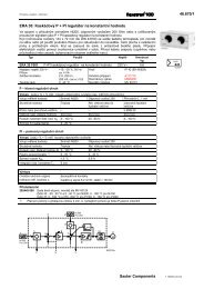
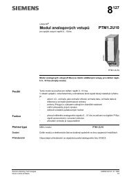
FIELDBUS<br />
INTERFACE<br />
1<br />
5<br />
24 V /0 V<br />
24 V<br />
0 V<br />
10 nF<br />
24 V<br />
5 V<br />
5 V<br />
Bus<br />
modules<br />
ELECTRONICS<br />
2<br />
6<br />
24 V<br />
24 V<br />
ELECTRONICS<br />
3<br />
4<br />
7<br />
8<br />
0 V<br />
0 V<br />
10 nF<br />
FIELDBUS<br />
INTERFACE<br />
1) 1 MΩ<br />
1) 2)<br />
2) 10 nF /500 V<br />
<strong>750</strong>-<strong>337</strong><br />
Technical Data<br />
Max. no. of I/O modules 64<br />
Fieldbus<br />
Max. input process image<br />
512 bytes<br />
Max. output process image<br />
512 bytes<br />
Configuration<br />
via PC or PLC<br />
No. of PDOs<br />
32 Tx / 32 Rx<br />
No. of SDOs<br />
2 server SDO<br />
Communication profile DS-301 V4.1<br />
Device profile DS 401 V2.0<br />
marginal check<br />
edge-triggered PDOs<br />
programmable error response<br />
COB ID Distribution<br />
SDO, standard<br />
Node ID Distribution<br />
DIP switches<br />
Other <strong>CANopen</strong> features<br />
NMT Slave<br />
Minimum Boot-up<br />
Variable PDO Mapping<br />
Emergency Message<br />
Life Guarding<br />
Voltage supply DC 24 V (-25 % ... +30 %)<br />
Max. input current (24V)<br />
500 mA<br />
Efficiency of the power supply 87 %<br />
Internal current consumption (5V) 350 mA<br />
Total current for I/O modules (5V) 1650 mA<br />
Isolation<br />
500 V system / supply<br />
Voltage via power jumper contacts DC 24 V (-25 % ... +30 %)<br />
Current via power jumper contacts (max.) DC 10 A<br />
General Specifications<br />
Operating temperature 0 °C ... +55 °C<br />
Wire connection CAGE CLAMP ®<br />
Cross sections 0.08 mm² ... 2.5 mm² / AWG 28 ... 14<br />
Stripped lengths<br />
8 ... 9 mm / 0.33 in<br />
Dimensions (mm) W x H x L 51 x 65 x 100<br />
Height from upper edge of DIN 35 rail<br />
Weight<br />
approx. 200 g<br />
Storage temperature -25 °C ... +85 °C<br />
Relative humidity (without condensation) 95 %<br />
Vibration resistance acc. to IEC 60068-2-6<br />
Shock resistance acc. to IEC 60068-2-27<br />
Degree of protection IP 20<br />
EMC 1-Immunity to interference acc. to EN 50082-2 (1996)<br />
EMC 1-Emission of interference acc. to EN 50081-2 (1994)<br />
EMC marine applications -<br />
Immunity to interference acc. to Germanischer Lloyd (1997)<br />
EMC marine applications -<br />
Emission of interference acc. to Germanischer Lloyd (1997)