Linear Slot Diffusers - Air Diffusion
Linear Slot Diffusers - Air Diffusion
Linear Slot Diffusers - Air Diffusion

You also want an ePaper? Increase the reach of your titles
YUMPU automatically turns print PDFs into web optimized ePapers that Google loves.
July 2011<br />
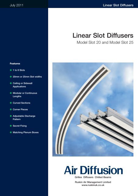
<strong>Linear</strong> <strong>Slot</strong> <strong>Diffusers</strong><br />
<strong>Linear</strong> <strong>Slot</strong> <strong>Diffusers</strong><br />
Model <strong>Slot</strong> 20 and Model <strong>Slot</strong> 25<br />
Features<br />
● 1 to 8 <strong>Slot</strong>s<br />
● 20mm or 25mm <strong>Slot</strong> widths<br />
● Ceiling or Sidewall<br />
Applications<br />
● Modular or Continuous<br />
Lengths<br />
● Curved Sections<br />
● Corner Pieces<br />
● Adjustable Discharge<br />
Pattern<br />
● Secret Fixing<br />
● Matching Plenum Boxes<br />
Grilles <strong>Diffusers</strong> Chilled Beams<br />
Ruskin <strong>Air</strong> Management Limited<br />
www.ruskinuk.co.uk
<strong>Linear</strong> <strong>Slot</strong> <strong>Diffusers</strong><br />
Contents<br />
Page<br />
Introduction Page 3<br />
Diffuser Specification Page 4<br />
<strong>Air</strong> Patterns Page 5<br />
Flange Styles Page 6<br />
Corner Sections Page 7<br />
Selection Procedure Page 8 and 9<br />
Selection Nomograms Page 10 and 11<br />
Standard Fixing Details Page 12<br />
Dimensions - Diffuser Page 13<br />
Ordering Information - Diffuser Page 14<br />
Plenum Boxes Page 15<br />
Dimensions - Plenum Boxes Page 16 and 17<br />
Ordering Information - Plenum Boxes Page 18<br />
Product Range Page 19<br />
2 www.air-diffusion.co.uk
<strong>Linear</strong> <strong>Slot</strong> <strong>Diffusers</strong><br />
Introduction<br />
The <strong>Air</strong> <strong>Diffusion</strong> Model <strong>Slot</strong> is designed<br />
to combine a high air change rate<br />
capacity with maximum flexibility in air<br />
pattern and volume control, suitable for<br />
either ceiling or sidewall applications<br />
linear slot diffusers offer unobtrusive good<br />
looks together with functional efficiency.<br />
<strong>Linear</strong> slot diffusers are particularly suited<br />
to large open plan offices, where<br />
changing occupancy layouts demand an<br />
air distribution system that includes built<br />
in adaptability to suit the relocation of<br />
internal partitioning.<br />
The standard flange border is 25mm but<br />
a multitude of different flange types are<br />
also available to allow the slot diffuser to<br />
be fully integrated with the ceiling design.<br />
Purpose designed and correctly selected<br />
co-ordinating sheet metal plenum boxes<br />
may also be provided to ensure the<br />
overall performance and characteristics of<br />
the diffuser are maintained. For uniform air<br />
distribution it is recommended that<br />
plenum boxes are fitted with an equalising<br />
grid.<br />
Available in two slot widths; a 20mm wide<br />
or 25mm wide and from 1 to 8 slot sizes<br />
offers the widest range of variations to<br />
provide the designer with performance for<br />
higher airflows when required. SLOT20<br />
and SLOT25 are both suitable for use in<br />
either Ceiling or Sidewall applications; the<br />
internal vanes are adjustable to provide<br />
either a horizontal or vertical air pattern<br />
discharge.<br />
www.air-diffusion.co.uk 3
<strong>Linear</strong> <strong>Slot</strong> <strong>Diffusers</strong><br />
Specification Diffuser<br />
Material<br />
Extruded aluminium.<br />
Finishes Standard<br />
Matt white RAL 9010 frame with<br />
anodised eggshell finish blades.<br />
Optional Frame<br />
Natural anodised. AA5.<br />
Other colours available to special order.<br />
Blades<br />
Standard material extruded Nylon 6 in<br />
either black or white. (See below).<br />
Blade Options<br />
Extruded aluminium in black or natural<br />
anodised only.<br />
End Flanges Single Units<br />
Supplied fitted both ends.<br />
<strong>Linear</strong> Runs<br />
Supplied fitted one end only of both end<br />
units or make-up pieces.<br />
Fixing Standard<br />
Side fixing twist in brackets Type F7.<br />
Sliding fit alignment strips, Type SP1 are<br />
supplied as standard with all linear<br />
diffuser modules for continuous<br />
appearance.<br />
Optional<br />
‘U’ bracket fixing to hemmed duct Type<br />
F6.<br />
Duct fixed into channel Type F7.<br />
Size Width<br />
1 – 8 slots in 20mm or 25mm spacing.<br />
Larger to special order if required.<br />
Length<br />
Any length up to 2400mm nominal<br />
opening size.<br />
<strong>Linear</strong> runs will be supplied in 2400mm<br />
long sections with end flanges as<br />
necessary. The exact length of the run will<br />
be made up with intermediate make-up<br />
sections.<br />
Where exact lengths are difficult to<br />
ascertain, we recommend that make-up<br />
sections include 200mm of solid mullion<br />
at one end for site trimming. e.g.1000mm<br />
make-up section cut at 1100mm with<br />
200mm solid mullion.<br />
Channel Stiffener<br />
A 12mm x12mm x 1.5mm channel<br />
stiffener is fitted to all open ended<br />
diffusers 2 slots and above. The stiffener<br />
is fitted approximately 50mm in from the<br />
diffuser ends.<br />
Blanking Plates (if specified)<br />
Supplied loose for cutting and fitting on<br />
site in sections.<br />
Extract Applications<br />
Unless specially requested otherwise,<br />
diffusers for use in extract mode will be<br />
supplied with pattern control blades fitted<br />
to match the appearance of supply units.<br />
Mitred Corners<br />
These are provided as 90° composite<br />
sections (refer to tables).<br />
Special Order<br />
Other angles can be supplied, a template<br />
or drawing will usually be required. This<br />
should always be as viewed from above.<br />
Ordering<br />
<strong>Diffusers</strong> should be ordered by the length<br />
of the opening into which they are fitted<br />
(nominal length). Specify slot 20 or slot<br />
25. Alternatively specify overall flange<br />
dimensions.<br />
Please refer to ordering information.<br />
4 www.air-diffusion.co.uk
<strong>Linear</strong> <strong>Slot</strong> <strong>Diffusers</strong><br />
<strong>Air</strong> Patterns<br />
Single direction supply<br />
Multidirection supply<br />
Extract<br />
Single direction with extract<br />
Supply with ceiling effect Extract Supply free space<br />
www.air-diffusion.co.uk 5
<strong>Linear</strong> <strong>Slot</strong> <strong>Diffusers</strong><br />
Flange Styles<br />
Standard 25mm, 32mm<br />
25mm (Standard)<br />
32mm<br />
Examples of Special Frames available on request<br />
Plank Ceiling Type<br />
Wide Plank Type<br />
Tegular Type<br />
Bevel Type<br />
<strong>Slot</strong> Diffuser to coordinate<br />
with ceiling, having extra<br />
wide outer flange with<br />
Tegular type edge.<br />
6 www.air-diffusion.co.uk
<strong>Linear</strong> <strong>Slot</strong> <strong>Diffusers</strong><br />
Corner Sections<br />
All dimensions shown are in mm.<br />
90° Mitred corner Multidirection supply<br />
T<br />
T<br />
T<br />
90<br />
L<br />
B<br />
*<br />
B<br />
*SPECIFY ANGLE<br />
T<br />
B = Overall width<br />
T = Overall length<br />
L = No. of slots<br />
25C <strong>Slot</strong> 20<br />
25C <strong>Slot</strong> 25<br />
32C <strong>Slot</strong> 20<br />
32C <strong>Slot</strong> 25<br />
No. of<br />
<strong>Slot</strong>s T B<br />
No. of<br />
<strong>Slot</strong>s T B<br />
No. of<br />
<strong>Slot</strong>s T B<br />
No. of<br />
<strong>Slot</strong>s T B<br />
1 200 70<br />
2 200 110<br />
3 300 150<br />
4 300 190<br />
5 400 230<br />
6 400 270<br />
7 600 310<br />
8 600 350<br />
1 200 75<br />
2 200 120<br />
3 300 165<br />
4 300 210<br />
5 400 255<br />
6 400 300<br />
7 600 345<br />
8 600 390<br />
1 200 84<br />
2 200 124<br />
3 300 164<br />
4 300 204<br />
5 400 244<br />
6 400 284<br />
7 600 324<br />
8 600 364<br />
1 200 89<br />
2 200 134<br />
3 300 179<br />
4 300 224<br />
5 400 269<br />
6 400 314<br />
7 600 359<br />
8 600 404<br />
www.air-diffusion.co.uk 7
<strong>Linear</strong> <strong>Slot</strong> <strong>Diffusers</strong><br />
<strong>Linear</strong> <strong>Slot</strong> <strong>Diffusers</strong> Selection Procedure<br />
Data<br />
1. Horizontal projection with ceiling effect<br />
nomogram readings are based on 10 °C<br />
cooling application. Use this nomogram<br />
for horizontal projection ceiling mounted<br />
diffusers or horizontal projection wall<br />
mounted diffusers with ceiling effect.<br />
2. Vertical/sidewall projection nomogram<br />
readings are based on Isothermal<br />
conditions in free space without wall<br />
effect. For supply/room temperature<br />
differential for vertical throw applications<br />
from ceiling see ‘Vertical Throw Multipliers<br />
for Differential Temperatures’ table.<br />
3. Use vertical/sidewall projection<br />
nomogram readings for sidewall supply<br />
application in free space. Please note that<br />
throw values apply to Isothermal<br />
conditions only and technical advice<br />
should be sought before using this<br />
method of supply for heating or cooling.<br />
4. Nomograms are based on 1.0 metre<br />
active slot lengths. For other active slot<br />
lengths see correction table.<br />
5. Pressure drop and sound power level<br />
readings obtained from nomograms are<br />
for slot diffusers only.<br />
6. For pressure drop additions and sound<br />
ratings for plenum boxes see separate<br />
table.<br />
7. When using slot diffuser in extract<br />
applications select performance using<br />
vertical/sidewall projection nomogram and<br />
ignore throw values.<br />
8. Sound values given for plenum boxes<br />
are approximate only and dependent on<br />
spigot entry conditions. Where sound<br />
requirements are critical acoustic lining of<br />
plenum boxes should be considered. Any<br />
space requirement to accommodate lining<br />
material must be added to selected box<br />
size.<br />
Selection Procedure<br />
The method set out below used in<br />
conjunction with the tabulated data allows<br />
slot 20 and 25 linear diffusers to be<br />
selected for supply or extract modes in<br />
either ceiling or sidewall applications.<br />
<strong>Air</strong> pattern is determined by the position<br />
of the pattern control blades as illustrated<br />
on page 3.<br />
Method – <strong>Slot</strong> Diffuser<br />
1. Establish volume flow rate per metre by<br />
dividing total air volume by the active slot<br />
length to give litres/metre.<br />
2. Using appropriate nomogram place a<br />
straight edge through the volume as<br />
calculated and position to pass through<br />
required throw value with satisfactory<br />
noise and pressure readings. Select<br />
suitable slot width and number of slots<br />
where straight edge passes through slot<br />
selection line. Finally realign straight edge<br />
through volume and slot selected points<br />
and read exact throw, sound and<br />
pressure figures.<br />
3. Readings obtained from the above<br />
using horizontal ceiling nomogram are<br />
based on 1 metre active slot length. (See<br />
note on nomogram). For other active<br />
lengths see ‘Active Length Correction<br />
Table’ for throw multiplier and sound level<br />
adjustment.<br />
4. Readings obtained from the methods<br />
above using vertical/sidewall projection<br />
nomogram are based on Isothermal<br />
conditions. For vertical throw values for<br />
temperature differential see ‘Vertical<br />
Throw Multipliers for Differential<br />
Temperatures’ correction table to obtain<br />
throw multiplier for varying number of<br />
slots.<br />
Method – Plenum Boxes<br />
1. Determined volume of plenum box by<br />
multiply chosen length of box x<br />
volume/metre of slot. (A maximum box<br />
size of 1.8m long is recommended).<br />
2. Select plenum spigot size from table on<br />
page 9 Maximum entry velocity of 3.5<br />
m/sec is recommended. Velocities in<br />
excess of this may lead to noise<br />
generation.<br />
3. From table of ‘Plenum Box Pressure<br />
Drops and Sound Ratings’ read off<br />
additional pressure drop to be added to<br />
slot diffuser pressure drop from<br />
nomogram. Ensure that plenum box<br />
sound power level is not more than slot<br />
diffuser reading if latter is design criteria.<br />
4. Where it is not possible to<br />
accommodate standard plenum boxes,<br />
special configurations are available, but<br />
should always maintain an equivalent<br />
cross-sectional area to a standard box.<br />
Consideration should also be given to the<br />
inlet spigot in respect of positioning,<br />
sizing and inlet velocities. Consult our<br />
technical department for detailed advice.<br />
Commissioning<br />
Calculation<br />
Volume 9m 3 /s) =<br />
Av. measured velocity (m/s) x<br />
active length (m) x<br />
number of slots x<br />
flow factor.<br />
The flow factor is simply the width of the<br />
slot in metres at the point where the<br />
velocity is measured.<br />
Maximum flow factors<br />
<strong>Slot</strong> 20 <strong>Slot</strong> 25<br />
Hor. Ver. Hor. Ver.<br />
0.009 0.011 0.011 0.011<br />
It should be noted that throw figures given<br />
apply to maximum blade openings in the<br />
configurations listed. If blade opening size<br />
as measured (in metres) should be<br />
substituted.<br />
Velocity measurement<br />
to measure the velocity it is important that<br />
an instrument with a measuring head<br />
small enough to fit the blade opening is<br />
used. The most suitable instrument is a<br />
hot wire anemometer. Take velocity<br />
readings at the blade openings at a<br />
maximum of 150mm centres along the<br />
active length to obtain an accurate<br />
average velocity and use this value in the<br />
formula above.<br />
Exhaust<br />
Procedure same as supply but with the<br />
anemometer probe reversed.<br />
8 www.air-diffusion.co.uk
<strong>Linear</strong> <strong>Slot</strong> <strong>Diffusers</strong><br />
<strong>Linear</strong> <strong>Slot</strong> <strong>Diffusers</strong> Selection Procedure<br />
Example<br />
An 8.0 metres long ceiling mounted horizontal<br />
throw slot diffuser is required to deliver a total<br />
volume of 600 L/sec with a maximum throw of<br />
6.1 metres to a terminal velocity of 0.50 m/s*.<br />
The active length of diffuser is 6.0 metres supplied<br />
from<br />
4–1500mm long supply plenums.<br />
Active slot volume rate =<br />
600 = 100 L/s/m<br />
6<br />
Active slot lengths are 1500mm and from ‘Active<br />
length Correction Table’, a multiplier of 1.15 must<br />
be applied.<br />
Nomogram throw x 1.15 = Required throw.<br />
Therefore: Required throw = 6.1m =<br />
1.15 1.15<br />
5.3m for nomogram selection.<br />
From nomogram using volume of 100 L/s/m and<br />
throw of 5.3m select 3 slot 20 diffuser with NR<br />
sound power level of 27 and total pressure drop<br />
of 17 Nm2. From ‘Active Length Correction<br />
Table’, obtain a sound power level correction of<br />
+ 2 NR giving a total of 29 NR.<br />
Volume for each plenum box =<br />
600 = 150 L/s.<br />
4<br />
From Plenum Box Spigot Sizing table opposite<br />
select spigot size relative to chosen inlet velocity.<br />
At 3.0 m/s we obtain a spigot size of 275mm<br />
diameter and referring to ‘Plenum Box Pressure<br />
Drops and Sound Ratings’ opposite, we can see<br />
that the plenum pressure drop is 8.0 Pa with a<br />
sound rating NR of 30.<br />
As sound power level reading is in excess of<br />
nomogram reading of 29 NR use latter figure. If<br />
29 NR is maximum critical design criteria<br />
increase spigot size to 300 diameter at 2.5 m/s<br />
and NR 25.<br />
Total pressure drop for slot diffuser and plenum<br />
box = 17 Pa + 8 Pa = 25 Pa.<br />
Plenum box drops and sound ratings<br />
Spigot velocity m/s<br />
1.5 2.0 2.5 3.0 3.5 4.0<br />
Pressure drop Pa* 2 4 6 8 12 16<br />
Sound power level N* 25 30 35 40<br />
*approximate – dependent upon entry conditions.<br />
Pressure drops additional to slot diffuser.<br />
Sound power level – use higher of slot or plenum value.<br />
Vertical throw multipliers for differential temperatures<br />
No. of Temperature differential ambient / supply (°C)<br />
slots -15 -10 -5 0 +5 +10 +15<br />
1 1.54 1.33 1.15 1.0 0.87 0.75 0.65<br />
2 2.0 1.59 1.26 1.0 0.79 0.63 0.50<br />
3 2.46 1.88 1.37 1.0 0.75 0.53 0.41<br />
4-8 2.71 1.95 1.4 1.0 0.71 0.51 0.37<br />
Plenum box spigot volumes (l/s)<br />
Spigot velocity m/s<br />
Diameter mm 1.5 2.0 2.5 3.0 3.5 4.0<br />
100 10 15 19 22 26 30<br />
125 18 24 30 35 41 47<br />
150 25 34 42 51 60 68<br />
175 35 46 58 70 82 94<br />
200 45 60 75 91 109 121<br />
225 58 77 96 117 137 151<br />
250 71 95 120 142 170 191<br />
275 86 115 145 172 205 230<br />
300 103 139 172 208 240 275<br />
325 120 160 200 240 280 320<br />
350 140 188 235 280 328 375<br />
400 185 245 310 370 430 495<br />
* Average room velocity.<br />
www.air-diffusion.co.uk 9
<strong>Linear</strong> <strong>Slot</strong> <strong>Diffusers</strong><br />
<strong>Linear</strong> <strong>Slot</strong> <strong>Diffusers</strong> Selection Nomogram<br />
Horizontal Projection with Ceiling Effect<br />
Volume litres/s/m<br />
1200<br />
1000<br />
900<br />
800<br />
700<br />
600<br />
500<br />
400<br />
300<br />
200<br />
150<br />
100<br />
Horizontal throw in – (to 0.50 m/s terminal velocity*)<br />
22<br />
20<br />
18<br />
16<br />
14<br />
12<br />
11<br />
10<br />
9<br />
8<br />
7<br />
6<br />
5<br />
4<br />
3<br />
NR Sound power level<br />
70<br />
60<br />
50<br />
45<br />
40<br />
35<br />
30<br />
25<br />
20<br />
15<br />
Total pressure – N/m 2 (Pa)<br />
100<br />
80<br />
60<br />
40<br />
30<br />
20<br />
10<br />
5<br />
Number of slots<br />
1<br />
2<br />
3<br />
4<br />
5<br />
6<br />
7<br />
8<br />
1<br />
2<br />
3<br />
4<br />
5<br />
6<br />
7<br />
Active length correction table<br />
Diffuser<br />
Active throw Sound level<br />
length (m) multiplier correction<br />
0.4 0.6 – 4 db<br />
0.5 0.7 – 3 db<br />
1.0 1.0 0<br />
1.5 1.15 – 2 db<br />
2.0 1.25 – 3 db<br />
3.0+ 1.30 – 5 db<br />
Throw is based on a temperature<br />
differential of 10 °C cooling to terminal<br />
velocity of 0.50 m/s* for 1 metre active<br />
length with a room height of 2.7m when<br />
mounted flush with an unobstructed flat<br />
ceiling.<br />
For other active lengths refer to above<br />
correction table.<br />
Throw factors are for throw in one<br />
direction by alternating throw direction at<br />
each blade length (600mm) a factor<br />
of x 0.6 can be used.<br />
All NR ratings are based on a room<br />
absorption of 8 db.<br />
*Average room velocity<br />
90<br />
80<br />
70<br />
2<br />
1<br />
8<br />
60<br />
50<br />
40<br />
30<br />
20<br />
15<br />
12<br />
<strong>Slot</strong> 20<br />
<strong>Slot</strong> 25<br />
10 www.air-diffusion.co.uk
<strong>Linear</strong> <strong>Slot</strong> <strong>Diffusers</strong><br />
<strong>Linear</strong> <strong>Slot</strong> <strong>Diffusers</strong> Selection Nomogram<br />
Vertical / Sidewall projection in free space<br />
(No Wall or Ceiling Effect)<br />
Volume litres/s/m<br />
600<br />
Throw – m (to 0.50 m/s terminal velocity*)<br />
NR Sound power Level<br />
Total pressure – N/m 2 (pa)<br />
Number of slots<br />
1<br />
Active length correction table<br />
Diffuser<br />
Active throw Sound level<br />
length (m) multiplier correction<br />
0.4 0.6 – 4 db<br />
0.5 0.7 – 3 db<br />
1.0 1.0 0<br />
1.5 1.15 – 2 db<br />
2.0 1.25 – 3 db<br />
3.0+ 1.30 – 5 db<br />
500<br />
400<br />
300<br />
200<br />
150<br />
100<br />
90<br />
12<br />
11<br />
10<br />
9<br />
8<br />
7<br />
6<br />
5<br />
4<br />
3<br />
2<br />
60<br />
50<br />
45<br />
40<br />
35<br />
30<br />
25<br />
12<br />
15<br />
100<br />
80<br />
40<br />
30<br />
10<br />
60<br />
20<br />
5<br />
2<br />
3<br />
4<br />
5<br />
6<br />
7<br />
8<br />
Throw is based on a isothermal conditions<br />
to a terminal velocity of<br />
0.50 m/s* for 1 metre active lengths.<br />
For other active lengths refer to above<br />
correction table.<br />
For other temperature differentials for<br />
vertical projection see throw multiplier<br />
correction tables.<br />
Throw factors are for throw in one<br />
direction by alternating throw direction at<br />
each blade length (600mm) a factor<br />
of x 0.6 can be used.<br />
All NR ratings are based on a room<br />
absorption of 8 db.<br />
*Average room velocity<br />
80<br />
1<br />
70<br />
60<br />
50<br />
40<br />
30<br />
20<br />
<strong>Slot</strong> 25<br />
www.air-diffusion.co.uk 11
<strong>Linear</strong> <strong>Slot</strong> <strong>Diffusers</strong><br />
Standard Fixing Details<br />
F6 (Plaster Fix) Using 32mm Flange<br />
65<br />
Hem Detail<br />
MINIMUM HEIGHT<br />
= D +100<br />
D<br />
20<br />
STANDARD<br />
SPIGOT<br />
INTERNAL<br />
LINING<br />
IF REQUIRED<br />
8<br />
4<br />
Wi<br />
Wo<br />
F7 (Suspension Fix) Using 32mm Flange<br />
65<br />
MINIMUM HEIGHT<br />
= D +100<br />
D<br />
20<br />
STANDARD<br />
SPIGOT<br />
INTERNAL<br />
LINING<br />
IF REQUIRED<br />
Wf<br />
F9 (Toggle Fix) 25 or 32mm Flange<br />
65<br />
20<br />
STANDARD<br />
SPIGOT<br />
MINIMUM HEIGHT<br />
= D +100<br />
D<br />
INTERNAL<br />
LINING<br />
IF REQUIRED<br />
Wf<br />
Number of <strong>Slot</strong>s<br />
1 2 3 4 5 6 7 8<br />
Dim Description 20 25 20 25 20 25 20 25 20 25 20 25 20 25 20 25<br />
Wo Overall width hemmed box 56 61 96 106 136 151 176 196 216 241 256 286 296 331 336 376<br />
Wi Clear inside hemmed box 48 53 88 98 128 143 168 188 208 233 248 278 288 323 328 368<br />
Wf Clear internal size-fork fixing 40 45 80 90 120 135 160 180 200 225 240 270 280 315 320 360<br />
12 www.air-diffusion.co.uk
<strong>Linear</strong> <strong>Slot</strong> <strong>Diffusers</strong><br />
Dimensions and Details<br />
E - (OVERALL WIDTH OF DUCT HAVING CONCEALED FIX BRACKETS)<br />
D - (MINIMUM INTERNAL DIMENSION FOR DUCT WITH STRAP FIXING)<br />
C - (INTERNAL DIMENSION FOR DUCT FIXED INTO CHANNEL)<br />
Note: ‘F6’ Type fixing<br />
shown – see page 7<br />
for all other options<br />
available.<br />
35<br />
44<br />
55<br />
15/22 10<br />
10 10 10 10 10<br />
F<br />
A<br />
A A F<br />
15/22<br />
25C <strong>Slot</strong> 20<br />
No. of<br />
<strong>Slot</strong>s A B C D E F<br />
1 20 70 40 48 56 25<br />
2 20 110 80 88 96 25<br />
3 20 150 120 128 136 25<br />
4 20 190 160 168 176 25<br />
5 20 230 200 208 216 25<br />
6 20 270 240 248 256 25<br />
7 20 310 280 288 296 25<br />
8 20 350 320 328 336 25<br />
32C <strong>Slot</strong> 20<br />
No. of<br />
<strong>Slot</strong>s A B C D E F<br />
1 20 84 40 48 56 32<br />
2 20 124 80 88 96 32<br />
3 20 164 120 128 136 32<br />
4 20 204 160 168 176 32<br />
5 20 244 200 208 216 32<br />
6 20 284 240 248 256 32<br />
7 20 324 280 288 296 32<br />
8 20 364 320 328 336 32<br />
25C Type slot run<br />
B<br />
25C <strong>Slot</strong> 25<br />
No. of<br />
<strong>Slot</strong>s A B C D E F<br />
1 25 75 45 53 61 25<br />
2 25 120 90 98 106 25<br />
3 25 165 135 143 151 25<br />
4 25 210 180 188 196 25<br />
5 25 255 225 233 241 25<br />
6 25 300 270 278 286 25<br />
7 25 345 315 323 331 25<br />
8 25 390 360 368 376 25<br />
32C <strong>Slot</strong> 25<br />
No. of<br />
<strong>Slot</strong>s A B C D E F<br />
1 25 89 45 53 61 32<br />
2 25 134 90 98 106 32<br />
3 25 179 135 143 151 32<br />
4 25 224 180 188 196 32<br />
5 25 269 225 233 241 32<br />
6 25 314 270 278 286 32<br />
7 25 359 315 323 331 32<br />
8 25 404 360 368 376 32<br />
32C Type slot run<br />
FRAME<br />
SIZE<br />
FRAME FRAME<br />
2400 *<br />
2400<br />
SIZE SIZE<br />
2400 2400<br />
*<br />
FRAME<br />
SIZE<br />
CEILING OPENING = OVERALL LESS 30mm<br />
OVERALL LENGTH<br />
CEILING OPENING = OVERALL LESS 44mm<br />
OVERALL LENGTH<br />
*Make up pieces manufactured to suit<br />
www.air-diffusion.co.uk 13
<strong>Linear</strong> <strong>Slot</strong> <strong>Diffusers</strong><br />
Ordering Information – <strong>Slot</strong> Diffuser<br />
Example<br />
Frame <strong>Slot</strong> No. of <strong>Slot</strong>s <strong>Slot</strong> Width End Flanges Fix Frame Finish Blade Finish<br />
I I I I I I I l<br />
25C <strong>Slot</strong> 4 25 E1 F6 3 4<br />
25C 25mm, flat<br />
surface flange<br />
32C 32mm, flat<br />
surface flange<br />
(suitable for<br />
plaster ceiling)<br />
SPC Other formats<br />
available on<br />
request<br />
1<br />
2<br />
3<br />
4<br />
5<br />
6<br />
7<br />
8<br />
20<br />
25<br />
E0 Open end<br />
E1 End plate one end<br />
E2 End plate two ends<br />
EP End plate<br />
ME Mitred End<br />
F6<br />
F7<br />
F9<br />
‘U’ Bracket fixing<br />
Side fixing twist<br />
in brackets<br />
Toggle fix<br />
SP Special fixing<br />
1 Natural anodised<br />
aluminium<br />
3 White RAL 9010<br />
matt<br />
6 Other colours<br />
available to<br />
special order<br />
94 Standard Black<br />
Nylon<br />
93 White Nylon<br />
1 Natural Anodised<br />
Aluminium<br />
(Aluminium blade)<br />
4 Black Anodised<br />
(Aluminium blade)<br />
6 Other colours<br />
available to<br />
special order<br />
The model described in the example above would be : 25C - <strong>Slot</strong> 4 - 25 - E1 - F6 - 3 - 4<br />
Important: please allow for any lighting zones when selecting plenum boxes<br />
Important Note: All orders must be addressed to AIR DIFFUSION, Ruskin <strong>Air</strong> Management Limited.<br />
14 www.air-diffusion.co.uk
<strong>Linear</strong> <strong>Slot</strong> <strong>Diffusers</strong><br />
Plenum Boxes<br />
Plenum Boxes<br />
Supplied unlined as standard<br />
with side entry spigot.<br />
Plenum boxes can be supplied<br />
internally lined with 12mm class<br />
“O” foam at extra cost. Apply<br />
to sales office for price.<br />
Specifications<br />
Material<br />
Standard is a minimum of 0.7mm thick<br />
galvanised or zinc coated steel.<br />
Construction<br />
Plenum boxes are generally fabricated in<br />
3 sections having tray ends, which are<br />
either mechanically joined or spot welded<br />
to form an airtight seal. Flush ends (no<br />
tray indents) are also available. As<br />
standard, spigots are side entry and<br />
located centrally. All boxes are supplied<br />
with plain edges, as standard, (F0 fixing).<br />
Standard Installation Method<br />
The tray ends of the plenum box<br />
incorporate a 15mm indent, on each side<br />
to allow for 8mm drop rod fixings, which<br />
gives space for holes to be drilled (by<br />
others) without disturbing the active<br />
section.<br />
Installation Options<br />
Fixing lugs can be factory fitted if<br />
preferred or special fixing methods (by<br />
others) may be used.<br />
For plenum boxes having flush ends<br />
separate hanging brackets/fixing lugs<br />
need to be fitted to allow independent<br />
support of diffuser and plenum box.<br />
Accessories<br />
Joggled style plenum boxes or pan<br />
adapters.<br />
Spigot dampers include; manual quadrant,<br />
teleflex operation or cord operated.<br />
6mm thick Class ‘O’ internal lining<br />
(Standard).<br />
Equalising grids (50% free area perforated<br />
mesh).<br />
Turning Vanes.<br />
Fixing lugs or special fixings (by others).<br />
Flush Ends (No Indent).<br />
Finish<br />
Self finish galvanised or zinc coated steel<br />
as standard.<br />
Black paint can be applied to internal<br />
faces if required. (At extra cost).<br />
Pressure Drops and Sound Rating<br />
The pressure drop given is<br />
for supply grille with<br />
damper fully open. When<br />
the grille is installed with<br />
plenum box, the pressure<br />
loss of the box has to be<br />
added to the grille.<br />
Spigot Velocity m/s<br />
1.5 2.0 2.5 3.0 3.5 4.0<br />
Pressure Drop Pa* 2 4 6 8 12 16<br />
Sound Power Level NR* - - 25 30 35 40<br />
* The figures given are approximate - dependent upon spigot entry conditions<br />
Plenum Box Spigot Volumes (l/s)<br />
Spigot Velocity m/s<br />
Diameter (mm) 1.5 2.0 2.5 3.0 3.5 4.0<br />
100 10 15 19 22 26 30<br />
125 18 24 30 35 41 47<br />
150 25 34 42 51 60 68<br />
175 35 46 58 70 82 94<br />
200 45 60 75 91 109 121<br />
225 58 77 96 117 137 151<br />
250 71 95 120 142 170 191<br />
275 86 115 145 172 205 230<br />
300 103 139 172 208 240 275<br />
325 120 160 200 240 280 320<br />
350 140 188 235 280 328 375<br />
400 185 245 310 370 430 495<br />
www.air-diffusion.co.uk 15
<strong>Linear</strong> <strong>Slot</strong> <strong>Diffusers</strong><br />
Plenum Box Dimensions<br />
Type PBL-1<br />
65<br />
*<br />
*<br />
Allow ‘D’ when cord operated<br />
damper fitted<br />
20<br />
8mm hole<br />
for support<br />
rods<br />
H<br />
D<br />
X<br />
C<br />
W<br />
Cord operated spigot damper<br />
L<br />
L + 30<br />
Order Detail<br />
Angle Bracket fixing available if required.<br />
C<br />
H L W D LH RH X<br />
- - - - - - -<br />
Type PBL-1 for F6 fixing<br />
* This becomes ‘D’ if spigot damper fitted<br />
65*<br />
8mm hole<br />
for support<br />
rods<br />
C<br />
D<br />
H<br />
20<br />
X<br />
L<br />
W<br />
L + 30<br />
Order Detail<br />
Boxes shown with Indented Ends.<br />
Plain End boxes also available.<br />
C<br />
H L W D LH RH X<br />
- - - - - - -<br />
16 www.air-diffusion.co.uk
<strong>Linear</strong> <strong>Slot</strong> <strong>Diffusers</strong><br />
Plenum Box Dimensions Continued<br />
Manual Quadrant Control Damper<br />
Open Blade DW 144 Casing Weight<br />
Model Ref * NDD Protrusion (mm) Leakage Class (Kg)<br />
CB 100 – C 0.56<br />
CB 125 – C 0.71<br />
CB 150 – C 0.85<br />
CB 160 C 0.91<br />
CB 200 C 1.17<br />
CB 250 20.5 C 1.53<br />
CB 300 45.5 C 1.92<br />
CB 315 53 C 2.05<br />
CB 350 70.5 C 2.35<br />
CB 355 73 C 2.40<br />
* NDD: Nominal duct diameter. Actual sizes are in accordance with BS EN 1506: 1998<br />
www.air-diffusion.co.uk 17
<strong>Linear</strong> <strong>Slot</strong> <strong>Diffusers</strong><br />
Ordering Information – Plenum Boxes<br />
Example<br />
Model Internal Lining Spigot Damper Options Dimensions<br />
PBL-1 U N 0<br />
Plenum Boxes<br />
PBL-1 <strong>Linear</strong> Plenum Box with<br />
either a circular or<br />
square side entry spigot<br />
PBL-2 <strong>Linear</strong> Plenum Box<br />
having either a circular<br />
or square top entry<br />
spigot<br />
PBL-3 <strong>Linear</strong> Plenum Box with<br />
joggle section having<br />
either a circular or<br />
square side entry spigot<br />
U – Standard Unlined<br />
Plenum Box<br />
L – 6mm Class ‘O’<br />
Internal Lining.<br />
(Standard)<br />
N – Plain spigot no<br />
damper.<br />
Q – Quadrant damper.<br />
T – Teleflex damper fitted<br />
to spigot.<br />
C – Cord operated<br />
damper fitted to spigot.<br />
0 – No options.<br />
1 – Internal faces painted<br />
black.<br />
2 – Equalising grid.<br />
3 – Fixing lugs fitted to<br />
side of plenum.<br />
4 – Profile ends on each<br />
end of plenum.<br />
5 – Hemmed Edge for<br />
secret strap fixing.<br />
See example<br />
below<br />
Dimensions PBL - 1, PBS - 2, Example<br />
)<br />
(<br />
Neck Size Plenum Height Circular Spigot<br />
OR<br />
Sq. / Rect.Spigot Centre Line<br />
Diameter Width x Height of Spigot<br />
L x W H ∅D C x E G<br />
450 x 450 350 250 0 0<br />
‘0’ Denotes Standard.<br />
Important Note: All orders must be addressed to AIR DIFFUSION, Ruskin <strong>Air</strong> Management Limited.<br />
Note: Redesign may occur which<br />
supersedes the information in this<br />
brochure. Pease refer to our website for<br />
latest information.<br />
18 www.air-diffusion.co.uk
<strong>Linear</strong> <strong>Slot</strong> <strong>Diffusers</strong><br />
Product Range<br />
● Swirl <strong>Diffusers</strong><br />
● Displacement Ventilation <strong>Diffusers</strong><br />
Floor Grilles<br />
● Perforated and Louvre Face Ceiling <strong>Diffusers</strong><br />
● High Induction <strong>Slot</strong> <strong>Diffusers</strong><br />
● <strong>Slot</strong> and Fixed Blade <strong>Linear</strong> <strong>Diffusers</strong><br />
● Cylinder and Jet Nozzle <strong>Diffusers</strong><br />
● Circular <strong>Diffusers</strong> and <strong>Air</strong> Valves<br />
● Floor Grilles<br />
● <strong>Linear</strong> Bar Grilles<br />
Swirl <strong>Diffusers</strong><br />
● Wall and Ceiling Grilles<br />
● External Louvres<br />
● Chilled Beam Panels<br />
● Systempac<br />
● Miscellaneous<br />
Wall and Ceiling Grilles<br />
Chilled Beam Panels<br />
www.air-diffusion.co.uk 19
<strong>Linear</strong> <strong>Slot</strong> <strong>Diffusers</strong><br />
Ruskin <strong>Air</strong> Management Limited<br />
a BS EN ISO 9001 registered company<br />
The statements made in this brochure or by our<br />
representatives in consequence of any enquiries<br />
arising out of this document are given for information<br />
purposes only. They are not intended to have any<br />
legal effect and the company is not to be regarded<br />
as bound thereby. The company will only accept<br />
obligations which are expressly negotiated for and<br />
agreed and incorporated into a written agreement<br />
made with its customers.<br />
Due to a policy of continuous product development<br />
the specification and details contained herein are<br />
subject to alteration without prior notice.<br />
Ruskin <strong>Air</strong> Management Limited<br />
Stourbridge Road, Bridgnorth, Shropshire,<br />
WV15 5BB England.<br />
Tel: 01746 761921<br />
Fax: 01746 760127<br />
Email: sales@air-diffusion.co.uk<br />
Website: www.air-diffusion.co.uk<br />
Part of Ruskin <strong>Air</strong> Management Limited