Structural Systems - Bridon
Structural Systems - Bridon
Structural Systems - Bridon

You also want an ePaper? Increase the reach of your titles
YUMPU automatically turns print PDFs into web optimized ePapers that Google loves.
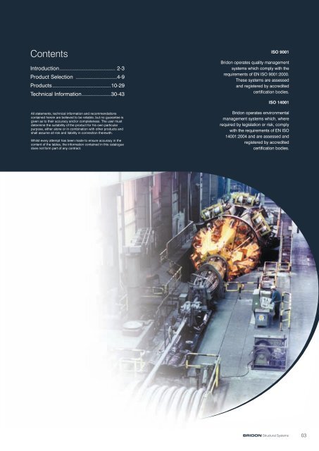
Contents<br />
Introduction...................................... 2-3<br />
Product Selection ............................4-9<br />
Products........................................10-29<br />
Technical Information....................30-43<br />
All statements, technical information and recommendations<br />
contained herein are believed to be reliable, but no guarantee is<br />
given as to their accuracy and/or completeness. The user must<br />
determine the suitability of the product for his own particular<br />
purpose, either alone or in combination with other products and<br />
shall assume all risk and liability in connection therewith.<br />
Whilst every attempt has been made to ensure accuracy in the<br />
content of the tables, the information contained in this catalogue<br />
does not form part of any contract.<br />
ISO 9001<br />
<strong>Bridon</strong> operates quality management<br />
systems which comply with the<br />
requirements of EN ISO 9001:2000.<br />
These systems are assessed<br />
and registered by accredited<br />
certification bodies.<br />
ISO 14001<br />
<strong>Bridon</strong> operates environmental<br />
management systems which, where<br />
required by legislation or risk, comply<br />
with the requirements of EN ISO<br />
14001:2004 and are assessed and<br />
registered by accredited<br />
certification bodies.<br />
BRIDON <strong>Structural</strong> <strong>Systems</strong><br />
03
Product Selection<br />
Suspension Bridges<br />
Major suspension bridges with long spans<br />
Locked Coil Strand<br />
Core of helically spun round wires in several layers.<br />
Cover of helically spun full lock wires in several layers.<br />
Layers are spun in opposite directions.<br />
Internal blocking compound and lubricant applied during stranding.<br />
•Very high axial stiffness<br />
•High breaking load due to ‘z’ shaped wires<br />
•Excellent clamping capabilities due to ‘z’ shaped wires<br />
•Even surface due to ‘z’ shaped wires<br />
•Torque balanced due to cross laying<br />
•High fatigue resistance<br />
•Excellent corrosion resistance due to<br />
Galvanised wires (zinc or Galfan ® )<br />
Internal blocking compound<br />
Locked surface due to ‘z’ shaped wires<br />
Additional coatings (if required)<br />
•Standards<br />
EN12385-10<br />
German TL Seile<br />
Norwegian Handbook 122<br />
•Diameter range 20 - 180 mm<br />
•Properties range<br />
367 - 31400 kN Minimum Breaking Load<br />
42 - 3780 MN Nominal Axial Stiffness<br />
See page 10<br />
Catenary cables<br />
Hanger cables<br />
Spiral Strand<br />
Helically spun round wires in several layers.<br />
Layers are spun in opposite directions.<br />
Internal blocking compound and lubricant can be applied<br />
during stranding.<br />
•High axial stiffness<br />
•High breaking load due to high strength wires<br />
•Good clamping capabilities<br />
•Torque balanced due to cross laying<br />
•High fatigue resistance<br />
•Excellent corrosion resistance due to<br />
Galvanised wires (zinc or Galfan ® )<br />
Internal blocking compound<br />
Additional coating (if required)<br />
•Standards<br />
EN12385-10<br />
ASTM A586<br />
•Diameter range 13 - 165mm<br />
•Properties range<br />
171 - 25200 kN Minimum Breaking Load<br />
19 - 2640 MN Nominal Axial Stiffness<br />
See page 11<br />
Catenary cables<br />
Hanger cables<br />
Handstrand cables<br />
Catwalk Cable<br />
04 BRIDON <strong>Structural</strong> <strong>Systems</strong>
Product Selection<br />
Cable Stayed Bridges<br />
Major cable stayed bridges with long spans<br />
Locked Coil Strand<br />
Spiral Strand<br />
Core of helically spun round wires in several layers.<br />
Cover of helically spun full lock wires in several layers.<br />
Layers are spun in opposite directions.<br />
Internal blocking compound and lubricant applied during stranding.<br />
•Very high axial stiffness<br />
•High breaking load due to ‘z’ shaped wires<br />
•Excellent clamping capabilities due to ‘z’ shaped wires<br />
•Even surface due to ‘z’ shaped wires<br />
•Torque balanced due to cross laying<br />
•High fatigue resistance<br />
•Excellent corrosion resistance due to<br />
Galvanised wires (zinc or Galfan ® )<br />
Internal blocking compound<br />
Locked surface due to ‘z’ shaped wires<br />
Additional coatings (if required)<br />
•Standards<br />
EN12385-10<br />
German TL Seile<br />
Norwegian Handbook 122<br />
•Diameter range 20 - 180 mm<br />
•Properties range<br />
367 - 31400 kN Minimum Breaking Load<br />
42 - 3780 MN Nominal Axial Stiffness<br />
See page 10<br />
Helically spun round wires in several layers.<br />
Layers are spun in opposite directions.<br />
Internal blocking compound and lubricant can be applied<br />
during stranding.<br />
•High axial stiffness<br />
•High breaking load due to high strength wires<br />
•Good clamping capabilities<br />
•Torque balanced due to cross laying<br />
•High fatigue resistance<br />
•Excellent corrosion resistance due to<br />
Galvanised wires (zinc or Galfan ® )<br />
Internal blocking compound<br />
Additional coating (if required)<br />
•Standards<br />
EN12385-10<br />
ASTM A586<br />
•Diameter range 13 - 165mm<br />
•Properties range<br />
171 - 25200 kN Minimum Breaking Load<br />
19 - 2640 MN Nominal Axial Stiffness<br />
See page 11<br />
Stay cables<br />
Stay cables<br />
BRIDON <strong>Structural</strong> <strong>Systems</strong> 05
Product Selection<br />
Tied Arch Bridges<br />
Major tied arch bridges with long spans<br />
Locked Coil Strand<br />
Core of helically spun round wires in several layers.<br />
Cover of helically spun full lock wires in several layers.<br />
Layers are spun in opposite directions.<br />
Internal blocking compound and lubricant applied during stranding.<br />
•Very high axial stiffness<br />
•High breaking load due to ‘z’ shaped wires<br />
•Excellent clamping capabilities due to ‘z’ shaped wires<br />
•Even surface due to ‘z’ shaped wires<br />
•Torque balanced due to cross laying<br />
•High fatigue resistance<br />
•Excellent corrosion resistance due to<br />
Galvanised wires (zinc or Galfan ® )<br />
Internal blocking compound<br />
Locked surface due to ‘z’ shaped wires<br />
Additional coatings (if required)<br />
•Standards<br />
EN12385-10<br />
German TL Seile<br />
Norwegian Handbook 122<br />
•Diameter range 20 - 180 mm<br />
•Properties range<br />
367 - 31400 kN Minimum Breaking Load<br />
42 - 3780 MN Nominal Axial Stiffness<br />
See page 10<br />
Cable Ties<br />
Spiral Strand<br />
Helically spun round wires in several layers.<br />
Layers are spun in opposite directions.<br />
Internal blocking compound and lubricant can be applied<br />
during stranding.<br />
•High axial stiffness<br />
•High breaking load due to high strength wires<br />
•Good clamping capabilities<br />
•Torque balanced due to cross laying<br />
•High fatigue resistance<br />
•Excellent corrosion resistance due to<br />
Galvanised wires (zinc or Galfan ® )<br />
Internal blocking compound<br />
Additional coating (if required)<br />
•Standards<br />
EN12385-10<br />
ASTM A586<br />
•Diameter range 13 - 165mm<br />
•Properties range<br />
171 - 25200 kN Minimum Breaking Load<br />
19 - 2640 MN Nominal Axial Stiffness<br />
See page 11<br />
Cable Ties<br />
06<br />
BRIDON <strong>Structural</strong> <strong>Systems</strong>
Product Selection<br />
Architectural Footbridges<br />
All types of small bridges including small suspension, cable stayed and arch bridges.<br />
Locked Coil Strand<br />
Core of helically spun round wires in several layers.<br />
Cover of helically spun full lock wires in several layers.<br />
Layers are spun in opposite directions.<br />
Internal blocking compound and lubricant applied during stranding.<br />
•Very high axial stiffness<br />
•High breaking load due to ‘z’ shaped wires<br />
•Excellent clamping capabilities due to ‘z’ shaped wires<br />
•Even surface due to ‘z’ shaped wires<br />
•Torque balanced due to cross laying<br />
•High fatigue resistance<br />
•Excellent corrosion resistance due to<br />
Galvanised wires (zinc or Galfan ® )<br />
Internal blocking compound<br />
Locked surface due to ‘z’ shaped wires<br />
Additional coatings (if required)<br />
•Standards<br />
EN12385-10<br />
German TL Seile<br />
•Diameter range 20 - 180 mm<br />
•Properties range<br />
367 - 31400 kN Minimum Breaking Load<br />
42 - 3780 MN Nominal Axial Stiffness<br />
See page 10<br />
Catenary cables<br />
Hanger cables<br />
Stay cables<br />
Spiral Strand<br />
Helically spun round wires in several layers.<br />
Layers are spun in opposite directions.<br />
Internal blocking compound and lubricant can be applied<br />
during stranding.<br />
•High axial stiffness<br />
•High breaking load due to high strength wires<br />
•Good clamping capabilities<br />
•Torque balanced due to cross laying<br />
•High fatigue resistance<br />
•Excellent corrosion resistance due to<br />
Galvanised wires (zinc or Galfan ® )<br />
Internal blocking compound<br />
Additional coating (if required)<br />
•Standards<br />
EN12385-10<br />
ASTM A586<br />
•Diameter range 13 - 165mm<br />
•Properties range<br />
171 - 25200 kN Minimum Breaking Load<br />
19 - 2640 MN Nominal Axial Stiffness<br />
See page 11<br />
Catenary cables<br />
Hanger cables<br />
Stay cables<br />
BRIDON <strong>Structural</strong> <strong>Systems</strong><br />
07
Product Selection<br />
Roof Structures<br />
Wide span, light weight roofs<br />
Locked Coil Strand<br />
Core of helically spun round wires in several layers.<br />
Cover of helically spun full lock wires in several layers.<br />
Layers are spun in opposite directions.<br />
Internal blocking compound and lubricant applied during stranding.<br />
•Very high axial stiffness<br />
•High breaking load due to ‘z’ shaped wires<br />
•Excellent clamping capabilities due to ‘z’ shaped wires<br />
•Even surface due to ‘z’ shaped wires<br />
•Torque balanced due to cross laying<br />
•High fatigue resistance<br />
•Excellent corrosion resistance due to<br />
Galvanised wires (zinc or Galfan ® )<br />
Internal blocking compound<br />
Locked surface due to ‘z’ shaped wires<br />
•Standards<br />
EN12385-10<br />
•Diameter range 20 - 180 mm<br />
•Properties range<br />
367 - 31400 kN Minimum Breaking Load<br />
42 - 3780 MN Nominal Axial Stiffness<br />
See page 10<br />
Catenary cables<br />
Hanger cables<br />
Stay cables<br />
Ring cables<br />
Radial cables<br />
Edge cables<br />
Spiral Strand<br />
Helically spun round wires in several layers.<br />
Layers are spun in opposite directions.<br />
Internal blocking compound and lubricant can be applied<br />
during stranding.<br />
•High axial stiffness<br />
•High breaking load due to high strength wires<br />
•Good clamping capabilities<br />
•Torque balanced due to cross laying<br />
•High fatigue resistance<br />
•Excellent corrosion resistance due to<br />
Galvanised wires (zinc or Galfan ® )<br />
Internal blocking compound<br />
•Standards<br />
EN12385-10<br />
ASTM A586<br />
•Diameter range 13 - 165mm<br />
•Properties range<br />
171 - 25200 kN Minimum Breaking Load<br />
19 - 2640 MN Nominal Axial Stiffness<br />
See page 11<br />
Catenary cables<br />
Hanger cables<br />
Stay cables<br />
Ring cables<br />
Radial cables<br />
Edge cables<br />
08<br />
BRIDON <strong>Structural</strong> <strong>Systems</strong>
Product Selection<br />
Stayed Masts and Towers<br />
Tall, slender masts and towers supported by cables<br />
Locked Coil Strand<br />
Core of helically spun round wires in several layers.<br />
Cover of helically spun full lock wires in several layers.<br />
Layers are spun in opposite directions.<br />
Internal blocking compound and lubricant applied during stranding.<br />
•Very high axial stiffness<br />
•High breaking load due to ‘z’ shaped wires<br />
•Excellent clamping capabilities due to ‘z’ shaped wires<br />
•Even surface due to ‘z’ shaped wires<br />
•Torque balanced due to cross laying<br />
•High fatigue resistance<br />
•Excellent corrosion resistance due to<br />
Galvanised wires (zinc or Galfan ® )<br />
Internal blocking compound<br />
Locked surface due to ‘z’ shaped wires<br />
Additional coatings (if required)<br />
•Standards<br />
EN12385-10<br />
•Diameter range 20 - 180 mm<br />
•Properties range<br />
367 - 31400 kN Minimum Breaking Load<br />
42 - 3780 MN Nominal Axial Stiffness<br />
See page 10<br />
Stay cables<br />
Spiral Strand<br />
Helically spun round wires in several layers.<br />
Layers are spun in opposite directions.<br />
Internal blocking compound and lubricant can be applied<br />
during stranding.<br />
•High axial stiffness<br />
•High breaking load due to high strength wires<br />
•Good clamping capabilities<br />
•Torque balanced due to cross laying<br />
•High fatigue resistance<br />
•Excellent corrosion resistance due to<br />
Galvanised wires (zinc or Galfan ® )<br />
Internal blocking compound<br />
Additional coating (if required)<br />
•Standards<br />
EN12385-10<br />
ASTM A586<br />
•Diameter range 13 - 165mm<br />
•Properties range<br />
171 - 25200 kN Minimum Breaking Load<br />
19 - 2640 MN Nominal Axial Stiffness<br />
See page 11<br />
Stay cables<br />
BRIDON <strong>Structural</strong> <strong>Systems</strong><br />
09
Products<br />
Locked Coil Strand (LC)<br />
Product Code /<br />
Strand Diameter<br />
Minimum<br />
Breaking Load<br />
Design Load GR,d =<br />
MBL / 1,5 / 1,1<br />
Nominal Metallic<br />
Cross Section<br />
Nominal Axial<br />
Stiffness<br />
Nominal<br />
Metallic Mass<br />
d<br />
MBL GR,d A<br />
EA Mass<br />
mm kN kN mm 2<br />
MN kg/m<br />
LC 20<br />
LC 25<br />
LC 30<br />
LC 35<br />
LC 40<br />
LC 45<br />
LC 50<br />
LC 55<br />
LC 60<br />
LC 65<br />
LC 70<br />
LC 75<br />
LC 80<br />
LC 85<br />
LC 90<br />
LC 95<br />
LC 100<br />
LC 105<br />
LC 110<br />
LC 115<br />
LC 120<br />
LC 125<br />
LC 130<br />
LC 135<br />
LC 140<br />
LC 145<br />
LC 150<br />
LC 155<br />
LC 160<br />
LC 165<br />
LC 170<br />
LC 175<br />
LC 180<br />
368<br />
574<br />
858<br />
1170<br />
1580<br />
2000<br />
2470<br />
3020<br />
3590<br />
4220<br />
4890<br />
5620<br />
6390<br />
7220<br />
8090<br />
9120<br />
10100<br />
11100<br />
12200<br />
13300<br />
14500<br />
15700<br />
16200<br />
17500<br />
18700<br />
20100<br />
21500<br />
23000<br />
24500<br />
26100<br />
27600<br />
29300<br />
31000<br />
223<br />
348<br />
520<br />
709<br />
958<br />
1212<br />
1497<br />
1830<br />
2176<br />
2558<br />
2964<br />
3406<br />
3873<br />
4376<br />
4903<br />
5527<br />
6121<br />
6727<br />
7394<br />
8061<br />
8788<br />
9515<br />
9818<br />
10606<br />
11333<br />
12182<br />
13030<br />
13939<br />
14848<br />
15818<br />
16727<br />
17758<br />
18788<br />
254<br />
398<br />
594<br />
808<br />
1090<br />
1390<br />
1710<br />
2090<br />
2490<br />
2920<br />
3390<br />
3890<br />
4420<br />
5000<br />
5600<br />
6310<br />
6990<br />
7710<br />
8460<br />
9280<br />
10100<br />
11000<br />
11900<br />
12920<br />
13900<br />
14910<br />
15900<br />
16990<br />
18100<br />
19250<br />
20400<br />
21650<br />
22900<br />
42<br />
66<br />
98<br />
133<br />
180<br />
229<br />
282<br />
345<br />
411<br />
482<br />
559<br />
642<br />
729<br />
824<br />
924<br />
1040<br />
1150<br />
1270<br />
1400<br />
1530<br />
1670<br />
1820<br />
1960<br />
2130<br />
2290<br />
2460<br />
2620<br />
2800<br />
2990<br />
3180<br />
3370<br />
3570<br />
3780<br />
2.04<br />
3.20<br />
4.77<br />
6.49<br />
8.76<br />
11.1<br />
13.7<br />
16.8<br />
20.0<br />
23.5<br />
27.2<br />
31.3<br />
35.5<br />
40.1<br />
45.0<br />
50.7<br />
56.2<br />
61.9<br />
68.0<br />
74.5<br />
81.1<br />
88.4<br />
95.6<br />
104<br />
112<br />
120<br />
128<br />
136<br />
145<br />
155<br />
164<br />
174<br />
184<br />
Figures shown are for guidance purposes only. For details specific to your requirement please contact <strong>Bridon</strong>.<br />
•Alternative sizes and constructions are availible to suit individual applications.<br />
•Minimising the number of different strand diameters can optimise costs.<br />
•All Stylite ® sockets are suitable for use with Locked Coil Strand. See pages 12 - 23<br />
•Swaged sockets are not suitable for use with Locked Coil Strand.<br />
•Strands with internal blocking material add 3% to nominal metallic mass.<br />
10<br />
BRIDON <strong>Structural</strong> <strong>Systems</strong>
Products<br />
Spiral Strand (SS)<br />
Product Code /<br />
Strand Diameter<br />
Minimum<br />
Breaking Load<br />
Design Load GR,d =<br />
MBL / 1,5 / 1,1<br />
Nominal Metallic<br />
Cross Section<br />
Nominal Axial<br />
Stiffness<br />
Nominal<br />
Metallic Mass<br />
d<br />
MBL GR,d A<br />
EA Mass<br />
mm kN kN mm 2<br />
MN kg/m<br />
SS 13 171 104 105<br />
19<br />
0.85<br />
SS 16 254 154 156<br />
27<br />
1.26<br />
SS 19 356 216 219<br />
38<br />
1.77<br />
SS 22 455 276 279<br />
49<br />
2.26<br />
SS 25 610 370 377<br />
66<br />
3.05<br />
SS 30 864 524 541<br />
95<br />
4.29<br />
SS 35 1190 719 731<br />
124<br />
5.91<br />
SS 40 1540 931 973<br />
160<br />
7.63<br />
SS 45 1960 1190 1200<br />
204<br />
9.73<br />
SS 50 2400 1460 1470<br />
242<br />
11.9<br />
SS 55 2920 1770 1790<br />
295<br />
14.6<br />
SS 60 3460 2100 2120<br />
350<br />
17.2<br />
SS 65 4070 2470 2500<br />
413<br />
20.4<br />
SS 70 4700 2850 2890<br />
462<br />
23.6<br />
SS 75 5420 3290 3330<br />
533<br />
27.3<br />
SS 80 5910 3580 3670<br />
569<br />
30.8<br />
SS 85 6680 4050 4150<br />
643<br />
34.8<br />
SS 90 7320 4440 4650<br />
721<br />
39.0<br />
SS 95 8160 4950 5190<br />
804<br />
43.5<br />
SS 100 9040 5480 5740<br />
890<br />
48.2<br />
SS 105 10200 6160 6340<br />
983<br />
53.1<br />
SS 110 11200 6760 6950<br />
1080<br />
58.3<br />
SS 115 12300 7440 7610<br />
1180<br />
63.7<br />
SS 120 13300 8060 8280<br />
1280<br />
69.4<br />
SS 125 14500 8760 8980<br />
1390<br />
75.3<br />
SS 130 15600 9470 9710<br />
1510<br />
81.4<br />
SS 135 16800 10200 10500<br />
1630<br />
87.8<br />
SS 140 18200 11000 11300<br />
1750<br />
94.4<br />
SS 145 19500 11800 12100<br />
1880<br />
102<br />
SS 150 20800 12600 13000<br />
2020<br />
108<br />
SS 155 22200 13500 13800<br />
2140<br />
113<br />
SS 160 23700 14300 14800<br />
2300<br />
121<br />
SS 165 25200 15300 15700<br />
2440<br />
128<br />
Figures shown are for guidance purposes only. For details specific to your requirement please contact <strong>Bridon</strong>.<br />
•Alternative sizes and constructions are availible to suit individual applications.<br />
•Minimising the number of different strand diameters can optimise costs.<br />
•Swaged sockets are suitable for Spiral Strand diameters up to 35mm. See pages 24 - 29<br />
•Stylite ® sockets are suitable for use with all Spiral Strand diameters. See pages 12 - 23<br />
•Strands with internal blocking material add 4% to nominal metallic mass<br />
BRIDON <strong>Structural</strong> <strong>Systems</strong><br />
11
Products<br />
L 1<br />
L 5<br />
L 2<br />
ø 1<br />
L 3<br />
L 6<br />
L 4<br />
Stylite Fork Sockets (ST-F)<br />
Product Code /<br />
Strand Diameter<br />
mm<br />
L 6 ø 1 Weight<br />
L 1 L 2 L 3 L 4 L 5<br />
Max Min Pin Pin Hole Socket<br />
Pin+<br />
Caps<br />
mm mm mm mm mm mm mm mm mm kg kg<br />
ST-F 25 275 88 121 73 58 57 55 45 46 8 1.7<br />
ST-F 30 330 105 154 86 70 71 68 55 56 15.5 2.9<br />
ST-F 35 385 120 175 100 82.5 85 79 65 66 22.5 4.7<br />
ST-F 40 410 130 187 120 95 90 82 75 76 31.5 6.6<br />
ST-F 45 420 145 210 124 100 95 90 80 81 43 8.4<br />
ST-F 50 440 155 221 144 115 100 93 90 91 56 11<br />
ST-F 55 477 168 233 155 115 110 100 100 101 60 14<br />
ST-F 60 520 180 250 168 125 120 110 110 111 74 18<br />
ST-F 65 565 195 267 187 137 129 115 120 121 94 24<br />
ST-F 70 610 210 285 202 148 137 125 130 131 117 30<br />
ST-F 75 645 225 307 211 154 147 135 135 136 141 34<br />
ST-F 80 690 240 322 226 166 157 145 145 146 167 42<br />
ST-F 85 735 255 348 240 177 167 155 155 156 209 51<br />
ST-F 90 780 270 366 255 188 178 165 165 166 245 61<br />
ST-F 95 825 285 383 274 200 186 175 175 176 291 72<br />
ST-F 100 870 300 421 294 211 197 185 185 186 352 87<br />
ST-F 105 905 315 438 298 218 206 195 190 191 394 96<br />
ST-F 110 950 330 458 318 228 215 205 200 201 457 112<br />
ST-F 115 995 345 474 332 240 225 215 210 211 517 128<br />
ST-F 120 1035 365 482 347 255 235 225 220 221 578 144<br />
ST-F 125 1080 375 501 361 266 245 230 230 231 649 164<br />
ST-F 130 1140 385 524 396 273 257 240 235 237 740 178<br />
ST-F 135 1185 400 539 410 279 267 250 240 242 825 192<br />
ST-F 140 1230 415 557 430 290 277 260 250 252 920 215<br />
ST-F 145 1276 425 575 445 306 287 270 260 262 1009 239<br />
ST-F 150 1321 440 587 465 315 297 280 270 272 1099 265<br />
Figures shown are for guidance purposes only. For details specific to your requirement please contact <strong>Bridon</strong>.<br />
•Suitable for Locked Coil Strand and Spiral Strand<br />
•Architectural socket design<br />
•100% efficiency, transmits the whole strand force<br />
Steelwork dimensions for guidance purposes:<br />
L 4 maximum swing of connecting linkage<br />
L 6 width of connecting steelwork including protective coating e.g. paint, galvanising, etc.<br />
For strand diameters larger than 150mm contact <strong>Bridon</strong>.<br />
12<br />
BRIDON <strong>Structural</strong> <strong>Systems</strong>
Products<br />
L 5<br />
L 1<br />
L 3<br />
L 6<br />
ø 2<br />
ø 1<br />
L 4<br />
Stylite Adjustable Fork Sockets (ST-AF)<br />
Product Code /<br />
Strand Diameter<br />
L<br />
ADJT<br />
6<br />
+/-<br />
L 3 L 4 L 5<br />
Max Min Max Min Pin<br />
L 1 ø 1<br />
ø 2<br />
Weight<br />
mm mm mm mm mm mm mm mm mm mm mm mm Metric kg<br />
ST-AF 25<br />
ST-AF 30<br />
ST-AF 35<br />
ST-AF 40<br />
ST-AF 45<br />
ST-AF 50<br />
ST-AF 55<br />
ST-AF 60<br />
ST-AF 65<br />
ST-AF 70<br />
ST-AF 75<br />
ST-AF 80<br />
ST-AF 85<br />
ST-AF 90<br />
ST-AF 95<br />
ST-AF 100<br />
ST-AF 105<br />
ST-AF 110<br />
ST-AF 115<br />
ST-AF 120<br />
ST-AF 125<br />
ST-AF 130<br />
ST-AF 135<br />
ST-AF 140<br />
ST-AF 145<br />
ST-AF 150<br />
631<br />
701<br />
815<br />
865<br />
894<br />
974<br />
1030<br />
1088<br />
1161<br />
1247<br />
1316<br />
1416<br />
1480<br />
1590<br />
1644<br />
1764<br />
1853<br />
1983<br />
2077<br />
2152<br />
2246<br />
2321<br />
2417<br />
2485<br />
2610<br />
2670<br />
531<br />
601<br />
695<br />
745<br />
774<br />
834<br />
890<br />
948<br />
1021<br />
1087<br />
1156<br />
1236<br />
1300<br />
1390<br />
1444<br />
1544<br />
1613<br />
1723<br />
1797<br />
1872<br />
1946<br />
2021<br />
2097<br />
2165<br />
2260<br />
2320<br />
50<br />
50<br />
60<br />
60<br />
60<br />
70<br />
70<br />
70<br />
70<br />
80<br />
80<br />
90<br />
90<br />
100<br />
100<br />
110<br />
120<br />
130<br />
140<br />
140<br />
150<br />
150<br />
160<br />
160<br />
175<br />
175<br />
121<br />
154<br />
175<br />
187<br />
210<br />
221<br />
233<br />
250<br />
267<br />
285<br />
307<br />
322<br />
348<br />
366<br />
383<br />
421<br />
438<br />
458<br />
474<br />
482<br />
501<br />
524<br />
539<br />
557<br />
575<br />
587<br />
73<br />
86<br />
100<br />
120<br />
124<br />
144<br />
155<br />
168<br />
187<br />
202<br />
211<br />
226<br />
240<br />
255<br />
274<br />
294<br />
298<br />
318<br />
332<br />
347<br />
361<br />
396<br />
410<br />
430<br />
445<br />
465<br />
58<br />
70<br />
82.5<br />
95<br />
100<br />
115<br />
115<br />
125<br />
137<br />
148<br />
154<br />
166<br />
177<br />
188<br />
200<br />
211<br />
218<br />
228<br />
240<br />
255<br />
266<br />
273<br />
279<br />
290<br />
306<br />
315<br />
57<br />
71<br />
85<br />
90<br />
95<br />
100<br />
110<br />
120<br />
129<br />
137<br />
147<br />
157<br />
167<br />
178<br />
186<br />
197<br />
206<br />
215<br />
225<br />
235<br />
245<br />
257<br />
267<br />
277<br />
287<br />
297<br />
55<br />
68<br />
79<br />
82<br />
90<br />
93<br />
100<br />
110<br />
115<br />
125<br />
135<br />
145<br />
155<br />
165<br />
175<br />
185<br />
195<br />
205<br />
215<br />
225<br />
230<br />
240<br />
250<br />
260<br />
270<br />
280<br />
45<br />
55<br />
65<br />
75<br />
80<br />
90<br />
100<br />
110<br />
120<br />
130<br />
135<br />
145<br />
155<br />
165<br />
175<br />
185<br />
190<br />
200<br />
210<br />
220<br />
230<br />
235<br />
240<br />
250<br />
260<br />
270<br />
46<br />
56<br />
66<br />
76<br />
81<br />
91<br />
101<br />
111<br />
121<br />
131<br />
136<br />
146<br />
156<br />
166<br />
176<br />
186<br />
191<br />
201<br />
211<br />
221<br />
231<br />
237<br />
242<br />
252<br />
262<br />
272<br />
87<br />
108<br />
120<br />
135<br />
145<br />
155<br />
170<br />
185<br />
205<br />
220<br />
235<br />
245<br />
265<br />
270<br />
285<br />
300<br />
315<br />
330<br />
345<br />
360<br />
375<br />
390<br />
400<br />
415<br />
430<br />
445<br />
M42 x 4.5<br />
M52 x 5.0<br />
M60 x 5.5<br />
M68 x 6.0<br />
M76 x 6.0<br />
M80 x 6.0<br />
M90 x 6.0<br />
M95 x 6.0<br />
M105 x 6.0<br />
M105 x 6.0<br />
M115 x 6.0<br />
M120 x 6.0<br />
M125 x 6.0<br />
M135 x 6.0<br />
M140 x 6.0<br />
M150 x 6.0<br />
M155 x 6.0<br />
M165 x 6.0<br />
M175 x 6.0<br />
M185 x 6.0<br />
M190 x 6.0<br />
M195 x 6.0<br />
M200 x 6.0<br />
M205 x 6.0<br />
M215 x 6.0<br />
M220 x 6.0<br />
20<br />
36<br />
49<br />
69<br />
87<br />
112<br />
131<br />
163<br />
210<br />
260<br />
309<br />
365<br />
447<br />
514<br />
591<br />
700<br />
816<br />
942<br />
1084<br />
1224<br />
1364<br />
1513<br />
1741<br />
1929<br />
2147<br />
2340<br />
Figures shown are for guidance purposes only. For details specific to your requirement please contact <strong>Bridon</strong>.<br />
•Suitable for Locked Coil Strand and Spiral Strand<br />
•Architectural socket design<br />
•100% efficiency, transmits the whole strand force<br />
Steelwork dimensions for guidance purposes:<br />
L 4 maximum swing of connecting linkage<br />
L 6 width of connecting steelwork including protective coating e.g. paint, galvanising, etc.<br />
For strand diameters larger than 150mm contact <strong>Bridon</strong>.<br />
Pin<br />
Hole<br />
Thread<br />
Size<br />
Assy<br />
BRIDON <strong>Structural</strong> <strong>Systems</strong><br />
13
Products<br />
L 1<br />
L 5<br />
L 6<br />
Stylite Fork Socket Adapter Bar (ST-FA)<br />
Product Code /<br />
Strand Diameter<br />
L 1 L 5 L 6 Thread Size<br />
Weight<br />
(Not Including Bar)<br />
mm mm mm mm Metric kg<br />
ST-FA 25 155 58 56 M42 x 4.5 5<br />
ST-FA 30 190 70 70 M52 x 5.0 9<br />
ST-FA 35 210 82 80 M60 x 5.5 13<br />
ST-FA 40 240 95 85 M68 x 6.0 18<br />
ST-FA 45 260 100 90 M72 x 6.0 25<br />
ST-FA 50 285 115 95 M80 x 6.0 32<br />
ST-FA 55 300 115 107 M90 X 6.0 44<br />
ST-FA 60 325 125 115 M95 X 6.0 54<br />
ST-FA 65 355 137 120 M105 x 6.0 68<br />
ST-FA 70 365 148 130 M105 x 6.0 80<br />
ST-FA 75 395 154 140 M115 x 6.0 98<br />
ST-FA 80 415 166 150 M120 x 6.0 117<br />
ST-FA 85 440 177 160 M125 x 6.0 136<br />
ST-FA 90 470 188 170 M135 x 6.0 165<br />
ST-FA 95 495 200 180 M140 x 6.0 195<br />
ST-FA 100 525 211 190 M150 x 6.0 237<br />
ST-FA 105 541 218 200 M155 x 6.0 261<br />
ST-FA 110 570 228 210 M165 x 6.0 299<br />
ST-FA 115 600 240 220 M175 x 6.0 348<br />
ST-FA 120 635 255 230 M185 x 6.0 411<br />
ST-FA 125 660 266 240 M190 x 6.0 463<br />
ST-FA 130 680 273 250 M195 x 6.0 492<br />
ST-FA 135 700 279 260 M200 x 6.0 532<br />
ST-FA 140 720 290 270 M205 x 6.0 589<br />
ST-FA 145 750 303 280 M215 x 6.0 652<br />
ST-FA 150 775 315 290 M220 X 6.0 726<br />
Figures shown are for guidance purposes only. For details specific to your requirement please contact <strong>Bridon</strong>.<br />
•Suitable for Locked Coil Strand and Spiral Strand<br />
•Architectural socket design<br />
•100% efficiency, transmits the whole strand force<br />
For strand diameters larger than 150mm contact <strong>Bridon</strong>.<br />
14<br />
BRIDON <strong>Structural</strong> <strong>Systems</strong>
Products<br />
L 2<br />
ø 1<br />
ø 2<br />
Stylite Plain Cylindrical Socket (ST-PC)<br />
Product Code /<br />
Strand Diameter<br />
L 2 ø 1 ø 2 Weight<br />
mm mm mm mm kg<br />
ST-PC 25 185 87 44 5<br />
ST-PC 30 220 108 46 11<br />
ST-PC 35 255 120 51 15<br />
ST-PC 40 260 135 57 20<br />
ST-PC 45 265 145 63 23<br />
ST-PC 30 265 155 69 26<br />
ST-PC 55 290 170 77 35<br />
ST-PC 60 315 185 82 45<br />
ST-PC 65 340 205 88 61<br />
ST-PC 70 365 220 96 75<br />
ST-PC 75 390 235 102 91<br />
ST-PC 80 415 245 107 104<br />
ST-PC 85 440 265 113 132<br />
STPC 90 465 270 119 139<br />
ST-PC 95 495 285 124 166<br />
ST-PC 100 520 300 132 193<br />
ST-PC 105 545 315 138 223<br />
ST-PC 110 570 330 144 255<br />
ST-PC 115 595 345 149 293<br />
ST-PC 120 620 360 155 332<br />
ST-PC 125 645 375 161 360<br />
ST-PC 130 670 390 167 421<br />
ST-PC 135 695 400 173 454<br />
ST-PC 140 720 415 178 508<br />
ST-PC 145 750 430 184 567<br />
ST-PC 150 775 445 190 627<br />
Figures shown are for guidance purposes only. For details specific to your requirement please contact <strong>Bridon</strong>.<br />
•Suitable for Locked Coil Strand and Spiral Strand<br />
•Architectural socket design<br />
•100% efficiency, transmits the whole strand force<br />
Steelwork dimensions for guidance purposes:<br />
ø 2 - Recommended hole size in supporting steelwork / split plate or "c" washer slot width<br />
For strand diameters larger than 150mm contact <strong>Bridon</strong>.<br />
BRIDON <strong>Structural</strong> <strong>Systems</strong><br />
15
Products<br />
L 2<br />
L 3<br />
ø 1<br />
ø 2<br />
Stylite Internal Thread Cylindrical Socket (ST-IC)<br />
Product Code /<br />
Strand Diameter<br />
L 2 L 3 ø 1 ø 2 Thread Size Weight<br />
mm mm mm mm mm Metric kg<br />
ST-IC 25 250 55 87 44 M56 x 5.5 8<br />
ST-IC 30 290 60 108 46 M72 x 6.0 14<br />
ST-IC 35 330 65 120 51 M80 x 6.0 19<br />
ST-IC 40 345 75 135 57 M90 x 6.0 25<br />
ST-IC 45 350 80 145 63 M95 x 6.0 30<br />
ST-IC 50 360 90 155 69 M100 x 6.0 35<br />
ST-IC 55 390 95 170 77 M110 x 6.0 46<br />
ST-IC 60 420 100 185 82 M120 x 6.0 59<br />
ST-IC 65 450 105 205 88 M135 x 6.0 78<br />
ST-IC 70 480 110 220 96 M145 x 6.0 95<br />
ST-IC 75 515 115 235 102 M155 x 6.0 117<br />
ST-IC 80 545 120 245 107 M165 x 6.0 132<br />
ST-IC 85 575 125 265 113 M175 x 6.0 166<br />
ST-IC 90 610 135 270 119 M180 x 6.0 177<br />
ST-IC 95 640 140 285 124 M190 x 6.0 208<br />
ST-IC 100 675 150 300 132 M200 x 6.0 242<br />
ST-IC 105 710 155 315 138 M210 x 6.0 281<br />
ST-IC 110 740 160 330 144 M220 x 6.0 321<br />
ST-IC 115 770 165 345 149 M230 x 6.0 367<br />
ST-IC 120 800 170 360 155 M240 x 6.0 414<br />
ST-IC 125 835 180 375 161 M245 x 6.0 453<br />
ST-IC 130 860 180 390 167 M260 x 6.0 523<br />
ST-IC 135 890 185 400 173 M265 x 6.0 564<br />
ST-IC 140 920 190 415 178 M275 x 6.0 630<br />
ST-IC 145 950 195 430 184 M285 x 6.0 698<br />
ST-IC 150 980 200 445 190 M295 x 6.0 771<br />
Figures shown are for guidance purposes only. For details specific to your requirement please contact <strong>Bridon</strong>.<br />
•Suitable for Locked Coil Strand and Spiral Strand<br />
•Architectural socket design<br />
•100% efficiency, transmits the whole strand force<br />
Steelwork dimensions for guidance purposes:<br />
ø 2 - Recommended hole size in supporting steelwork / split plate or "c" washer slot width<br />
For strand diameters larger than 150mm contact <strong>Bridon</strong>.<br />
16<br />
BRIDON <strong>Structural</strong> <strong>Systems</strong>
Products<br />
L 2<br />
L 3 L 4<br />
ø 1<br />
ø 2<br />
ø 3<br />
L 5<br />
Stylite Internal/External Thread Cylindrical Socket (ST-IEC)<br />
Product Code /<br />
Strand Diameter<br />
L 2 L 3 L 4 L 5 ø 1 ø 2 ø 3<br />
Thread<br />
Size<br />
Socket<br />
Weight<br />
Nut<br />
mm mm mm mm mm mm mm mm Metric kg kg<br />
ST-IEC 25 250 55 40 200 100 110 140 M56 x 5.5 10 2<br />
ST-IEC 30 290 60 45 235 106 115 155 M72 x 6.0 11 3<br />
ST-IEC 35 330 65 50 275 125 135 175 M80 x 6.0 19 4<br />
ST-IEC 40 345 75 60 290 132 142 190 M90 x 6.0 21 7<br />
ST-IEC 45 350 80 66 295 150 160 210 M95 x 6.0 30 9<br />
ST-IEC 50 360 90 72 305 160 170 225 M100 x 6.0 35 11<br />
ST-IEC 55 390 95 78 335 180 190 250 M110 x 6.0 50 14<br />
ST-IEC 60 420 100 84 365 190 200 265 M120 x 6.0 59 18<br />
ST-IEC 65 450 105 88 390 212 222 290 M135 x 6.0 79 22<br />
ST-IEC 70 480 110 96 420 224 234 310 M145 x 6.0 94 28<br />
ST-IEC 75 515 115 104 455 236 246 325 M155 x 6.0 110 33<br />
ST-IEC 80 545 120 112 485 250 260 345 M165 x 6.0 131 40<br />
ST-IEC 85 575 125 120 505 265 275 365 M175 x 6.0 153 48<br />
ST-IEC 90 610 135 130 540 280 290 385 M180 x 6.0 184 58<br />
ST-IEC 95 640 140 130 570 300 310 410 M190 x 6.0 227 64<br />
ST-IEC 100 675 150 140 605 315 325 430 M200 x 6.0 264 76<br />
ST-IEC 105 710 155 144 630 335 345 455 M210 x 6.0 315 87<br />
ST-IEC 110 740 160 156 660 355 365 480 M220 x 6.0 374 104<br />
ST-IEC 115 770 165 168 690 355 365 490 M230 x 6.0 374 122<br />
ST-IEC 120 800 170 168 720 375 385 520 M240 x 6.0 441 138<br />
ST-IEC 125 835 180 176 740 400 415 550 M245 x 6.0 530 161<br />
ST-IEC 130 860 180 176 765 400 415 560 M260 x 6.0 521 173<br />
ST-IEC 135 890 185 176 795 425 440 585 M265 x 6.0 631 182<br />
ST-IEC 140 920 190 192 825 425 440 595 M275 x 6.0 630 212<br />
ST-IEC 145 950 195 192 855 450 465 620 M285 x 6.0 750 223<br />
ST-IEC 150 980 200 192 885 450 465 630 M295 x 6.0 745 237<br />
Figures shown are for guidance purposes only. For details specific to your requirement please contact <strong>Bridon</strong>.<br />
•Suitable for Locked Coil Strand and Spiral Strand<br />
•Architectural socket design<br />
•100% efficiency, transmits the whole strand force<br />
Steelwork dimensions for guidance purposes:<br />
ø 2 - Recommended hole size in supporting steelwork to suit bearing nut<br />
For strand diameters larger than 150mm contact <strong>Bridon</strong>.<br />
BRIDON <strong>Structural</strong> <strong>Systems</strong><br />
17
Products<br />
L 2<br />
L 3<br />
ø 1<br />
ø 2<br />
Stylite Conical Socket (ST-C)<br />
Product Code /<br />
Strand Diameter<br />
L 2 L 3 ø 1 ø 2<br />
Thread Size Weight<br />
mm<br />
mm<br />
mm<br />
mm<br />
mm<br />
Metric<br />
kg<br />
ST-C 25 310<br />
65<br />
87 58 M42 x 4.5<br />
ST-C 30 352<br />
72<br />
108 66 M52 x 5.0<br />
ST-C 35 404<br />
79<br />
120 74 M60 x 5.5<br />
ST-C 40 420<br />
90<br />
135 84 M68 x 6.0<br />
ST-C 45 426<br />
96<br />
145 93 M76 x 6.0<br />
ST-C 50 447<br />
107<br />
155 102 M80 x 6.0<br />
ST-C 55 478<br />
113<br />
170 114 M90 x 6.0<br />
ST-C 60 509<br />
119<br />
185 122 M95 x 6.0<br />
ST-C 65 545<br />
125<br />
205 130 M105 x 6.0<br />
ST-C 70 581<br />
131<br />
220 142 M105 x 6.0<br />
ST-C 75 616<br />
136<br />
235 150 M115 x 6.0<br />
ST-C 80 657<br />
142<br />
245 159 M120 x 6.0<br />
ST-C 85 688<br />
148<br />
265 170 M125 x 6.0<br />
ST-C 90 734<br />
159<br />
270 179 M135 x 6.0<br />
ST-C 95 765<br />
165<br />
285 187 M140 x 6.0<br />
ST-C 100 812<br />
177<br />
300 197 M150 x 6.0<br />
ST-C 105 858<br />
183<br />
315 206 M155 x 6.0<br />
ST-C 110 899<br />
189<br />
330 214 M165 x 6.0<br />
ST-C 115 940<br />
195<br />
345 224 M175 x 6.0<br />
ST-C 120 971<br />
201<br />
360 233 M185 x 6.0<br />
ST-C 125 1017<br />
212<br />
375 241 M190 x 6.0<br />
ST-C 130 1042<br />
212<br />
390 250 M195 x 6.0<br />
ST-C 135 1083<br />
218<br />
400 258 M200 x 6.0<br />
ST-C 140 1114<br />
224<br />
415 265 M205 x 6.0<br />
ST-C 145 1160<br />
230<br />
430 276 M215 x 6.0<br />
ST-C 150 1191<br />
236<br />
445 284 M220 x 6.0<br />
7<br />
12<br />
17<br />
22<br />
28<br />
33<br />
44<br />
54<br />
70<br />
89<br />
106<br />
122<br />
151<br />
163<br />
188<br />
222<br />
258<br />
294<br />
336<br />
375<br />
412<br />
468<br />
508<br />
562<br />
629<br />
689<br />
Figures shown are for guidance purposes only. For details specific to your requirement please contact <strong>Bridon</strong>.<br />
•Suitable for Locked Coil Strand and Spiral Strand<br />
•Architectural socket design<br />
•100% efficiency, transmits the whole strand force<br />
For strand diameters larger than 150mm contact <strong>Bridon</strong>.<br />
18<br />
BRIDON <strong>Structural</strong> <strong>Systems</strong>
Products<br />
ø 1<br />
L 2<br />
Stylite Ring Connector (ST-RC)<br />
Product Code /<br />
Strand Diameter<br />
Max<br />
L 2<br />
Min<br />
Max Adjustment<br />
+/-<br />
ø 1<br />
Thread Size<br />
Weight<br />
mm<br />
mm<br />
mm<br />
mm<br />
mm<br />
Metric<br />
kg<br />
ST - RC 25 730<br />
640<br />
45 87 M 42 x 4.5 16<br />
ST - RC 30 815<br />
725<br />
45 108 M 52 x 5.0 29<br />
ST - RC 35 925<br />
835<br />
45 120 M 60 x 5.5 39<br />
ST - RC 40 965<br />
875<br />
45 135 M 68 x 6.0 53<br />
ST - RC 45 975<br />
885<br />
45 145 M 76 x 6.0 66<br />
ST - RC 50 1020<br />
930<br />
45 155 M 80 x 6.0 79<br />
ST - RC 55 1085<br />
995<br />
45 170 M 90 x 6.0 105<br />
ST - RC 60 1150<br />
1060<br />
45 185 M 95 x 6.0 128<br />
ST - RC 65 1215<br />
1125<br />
45 205 M 105 x 6.0 166<br />
ST - RC 70 1300<br />
1210<br />
45 220 M 105 x 6.0 205<br />
ST - RC 75 1370<br />
1280<br />
45 235 M 115 x 6.0 244<br />
ST - RC 80 1455<br />
1365<br />
45 245 M 120 x 6.0 281<br />
ST - RC 85 1520<br />
1430<br />
45 265 M 125 x 6.0 343<br />
ST - RC 90 1615<br />
1525<br />
45 270 M 135 x 6.0 376<br />
ST - RC 95 1680<br />
1590<br />
45 285 M 140 x 6.0 432<br />
ST - RC 100 1775<br />
1685<br />
45 300 M 150 x 6.0 512<br />
ST - RC 105 1870<br />
1780<br />
45 315 M 155 x 6.0 590<br />
ST - RC 110 1955<br />
1865<br />
45 330 M 165 x 6.0 675<br />
ST - RC 115 2040<br />
1950<br />
45 345 M 175 x 6.0 772<br />
ST - RC 120 2105<br />
2015<br />
45 360 M 185 x 6.0 866<br />
ST - RC 125 2195<br />
2105<br />
45 375 M 190 x 6.0 951<br />
ST - RC 130 2250<br />
2160<br />
45 390 M 195 x 6.0 1071<br />
ST - RC 135 2335<br />
2245<br />
45 400 M 200 x 6.0 1161<br />
ST - RC 140 2400<br />
2310<br />
45 415 M 205 x 6.0 1280<br />
ST - RC 145 2495<br />
2405<br />
45 430 M 215 x 6.0 1434<br />
ST - RC 150 2560<br />
2470<br />
45 445 M 220 x 6.0 1567<br />
Figures shown are for guidance purposes only. For details specific to your requirement please contact <strong>Bridon</strong>.<br />
•Suitable for Locked Coil Strand and Spiral Strand<br />
•Architectural socket design<br />
•100% efficiency, transmits the whole strand force<br />
For strand diameters larger than 150mm contact <strong>Bridon</strong>.<br />
BRIDON <strong>Structural</strong> <strong>Systems</strong><br />
19
Products<br />
L 4<br />
L 1<br />
L 3<br />
L 2<br />
Stylite Block Socket (ST-B)<br />
Product Code /<br />
Strand Diameter<br />
L 1 L 2 L 3 L 4 Thread Size Weight<br />
mm mm mm mm mm Metric kg<br />
ST-B 25 160 185 87 232 M 30 x 3.5<br />
ST-B 30 180 220 105 264 M 36 x 4.0<br />
ST-B 35 200 255 125 296 M 42 x 4.5<br />
ST-B 40 215 260 140 327 M 48 x 5.0<br />
ST-B 45 250 265 145 378 M 56 x 5.5<br />
ST-B 50 260 265 155 404 M 64 x 6.0<br />
ST-B 55 300 290 170 444 M 64 x 6.0<br />
ST-B 60 320 315 185 480 M 68 x 6.0<br />
ST-B 65 340 340 205 500 M 76 x 6.0<br />
ST-B 70 385 365 220 565 M 80 x 6.0<br />
ST-B 75 390 395 240 570 M 85 x 6.0<br />
ST-B 80 400 415 245 600 M 90 x 6.0<br />
ST-B 85 430 440 265 630 M 95 x 6.0<br />
ST-B 90 475 465 270 695 M 100 x 6.0<br />
ST-B 95 480 495 285 700 M 105 x 6.0<br />
ST-B 100 560 520 300 800 M 110 x 6.0<br />
ST-B 105 565 545 315 815 M 115 x 6.0<br />
ST-B 110 570 570 330 830 M 120 x 6.0<br />
ST-B 115 580 595 345 860 M 125 x 6.0<br />
ST-B 120 585 620 360 875 M 130 x 6.0<br />
ST-B 125 590 645 375 890 M 135 x 6.0<br />
ST-B 130 630 670 390 945 M 140 x 6.0<br />
ST-B 135 650 695 400 970 M 145 x 6.0<br />
ST-B 140 670 720 415 1000 M 150 x 6.0<br />
ST-B 145 695 750 430 1035 M 155 x 6.0<br />
ST-B 150 720 775 445 1070 M 160 x 6.0<br />
15<br />
24<br />
37<br />
47<br />
62<br />
72<br />
95<br />
123<br />
143<br />
195<br />
218<br />
256<br />
300<br />
368<br />
400<br />
528<br />
584<br />
643<br />
736<br />
805<br />
875<br />
1010<br />
1106<br />
1226<br />
1369<br />
1509<br />
Figures shown are for guidance purposes only. For details specific to your requirement please contact <strong>Bridon</strong>.<br />
•Suitable for Locked Coil Strand and Spiral Strand<br />
•Architectural socket design<br />
•100% efficiency, transmits the whole strand force<br />
For strand diameters larger than 150mm contact <strong>Bridon</strong>.<br />
20<br />
BRIDON <strong>Structural</strong> <strong>Systems</strong>
Products<br />
ø 1<br />
L 6<br />
L 3<br />
L 1<br />
L 8<br />
L 4 L 5<br />
L 7<br />
L 9<br />
L 2<br />
Stylite Crossheads (ST-CH)<br />
L<br />
Product Code /<br />
6<br />
ø 1<br />
Thread<br />
L<br />
Strand Diameter 1 L 2 L 3 L 4 L 5 L 7 L 8 L 9 Size<br />
Max Min<br />
Pin<br />
Pin<br />
Hole<br />
mm mm mm mm mm mm mm mm mm mm mm mm mm Metric<br />
ST-CH 25 160 72 121 73 66 56 55 145 232 211 45<br />
ST-CH 30 180 84 154 86 74 71 68 170 264 244 55<br />
ST-CH 35 200 96 175 100 87 85 79 210 296 297 65<br />
ST-CH 40 215 112 187 120 98 90 82 225 327 323 75<br />
ST-CH 45 250 128 210 124 106 95 90 250 378 356 80<br />
ST-CH 50 260 144 221 144 120 100 93 280 404 400 90<br />
ST-CH 55 300 144 233 155 132 110 100 310 444 442 100<br />
ST-CH 60 320 160 250 168 141 120 110 335 480 476 110<br />
ST-CH 65 340 160 267 187 155 129 115 365 500 520 120<br />
ST-CH 70 385 180 285 202 167 137 125 390 565 557 130<br />
ST-CH 75 390 180 307 211 175 147 135 410 570 585 135<br />
ST-CH 80 400 200 322 226 188 157 145 440 600 628 145<br />
ST-CH 85 430 200 348 240 203 167 155 470 630 673 155<br />
ST-CH 90 475 220 366 255 216 178 165 500 695 716 165<br />
ST-CH 95 480 220 383 274 232 186 175 525 700 757 175<br />
ST-CH 100 560 240 421 294 245 197 185 565 800 810 185<br />
ST-CH 105 565 250 438 298 252 206 195 580 815 832 190<br />
ST-CH 110 570 260 458 318 262 215 205 605 830 867 200<br />
ST-CH 115 580 280 474 332 277 225 215 635 860 912 210<br />
ST-CH 120 585 290 482 347 289 235 225 660 875 949 220<br />
ST-CH 125 590 300 501 361 303 245 230 680 890 983 230<br />
ST-CH 130 630 315 524 396 273 257 240 676 945 949 235<br />
ST-CH 135 650 325 539 410 279 267 250 715 975 994 240<br />
ST-CH 140 670 340 557 430 290 277 260 740 1010 1030 250<br />
ST-CH 145 695 345 575 445 306 287 270 775 1040 1081 260<br />
ST-CH 150 720 360 587 465 315 297 280 800 1080 1115 270<br />
46<br />
56<br />
66<br />
76<br />
81<br />
91<br />
101<br />
111<br />
121<br />
131<br />
136<br />
146<br />
156<br />
166<br />
176<br />
186<br />
191<br />
201<br />
211<br />
221<br />
231<br />
237<br />
242<br />
252<br />
262<br />
272<br />
M 30 x 3.5<br />
M 36 x 4.0<br />
M 42 x 4.5<br />
M 48 x 5.0<br />
M 56 x 5.5<br />
M 64 x 6.0<br />
M 64 x 6.0<br />
M 68 x 6.0<br />
M 76 x 6.0<br />
M 80 x 6.0<br />
M 85 x 6.0<br />
M 90 x 6.0<br />
M 95 x 6.0<br />
M 100 x 6.0<br />
M 105 x 6.0<br />
M 110 x 6.0<br />
M 115 x 6.0<br />
M 120 x 6.0<br />
M 125 x 6.0<br />
M 130 x 6.0<br />
M 135 x 6.0<br />
M 135 x 6.0<br />
M 140 x 6.0<br />
M 145 x 6.0<br />
M 150 x 6.0<br />
M 155 x 6.0<br />
Figures shown are for guidance purposes only. For details specific to your requirement please contact <strong>Bridon</strong>.<br />
•Suitable for Locked Coil Strand and Spiral Strand<br />
•Architectural socket design<br />
•100% efficiency, transmits the whole strand force<br />
Steelwork dimensions for guidance purposes:<br />
L 4 maximum swing of connecting linkage<br />
L 6 width of connecting steelwork including protective coating e.g. paint, galvanising, etc.<br />
For strand diameters larger than 150mm contact <strong>Bridon</strong>.<br />
BRIDON <strong>Structural</strong> <strong>Systems</strong><br />
21
Products<br />
ø 1<br />
L 5<br />
L 2<br />
L 4<br />
L 6<br />
Stylite Hammerhead Socket (ST-H)<br />
Product Code /<br />
Strand Diameter<br />
L 2 L 4 L 5 L 6 ø 1 Weight<br />
mm mm mm mm mm mm kg<br />
ST-H 50 265 70<br />
240 185<br />
ST-H 55 290 75<br />
265 205<br />
ST-H 60 315 80<br />
285 225<br />
ST-H 65 340 85<br />
310 245<br />
ST-H 70 370 90<br />
335 260<br />
ST-H 75 395 95<br />
360 280<br />
ST-H 80 420 100<br />
380 300<br />
ST-H 85 445 110<br />
405 315<br />
ST-H 90 475 115<br />
430 335<br />
ST-H 95 500 120<br />
455 355<br />
ST-H 100 525 125<br />
475 370<br />
ST-H 105 550 130<br />
500 390<br />
ST-H 110 580 140<br />
525 410<br />
ST-H 115 605 145<br />
550 430<br />
ST-H 120 630 150<br />
570 445<br />
ST-H 125 655 160<br />
595 465<br />
ST-H 130 685 190<br />
620 485<br />
ST-H 135 710 210<br />
645 500<br />
ST-H 140 735 215<br />
665 520<br />
ST-H 145 760 220<br />
690 540<br />
ST-H 150 790 230<br />
715 555<br />
170<br />
185<br />
200<br />
210<br />
225<br />
250<br />
260<br />
270<br />
290<br />
305<br />
315<br />
340<br />
350<br />
360<br />
375<br />
395<br />
405<br />
410<br />
430<br />
440<br />
455<br />
30<br />
38<br />
48<br />
61<br />
74<br />
91<br />
109<br />
130<br />
155<br />
186<br />
209<br />
243<br />
282<br />
320<br />
362<br />
417<br />
496<br />
575<br />
639<br />
701<br />
780<br />
Figures shown are for guidance purposes only. For details specific to your requirement please contact <strong>Bridon</strong>.<br />
•Suitable for Locked Coil Strand and Spiral Strand<br />
•Architectural socket design<br />
•100% efficiency, transmits the whole strand force<br />
For strand diameters larger than 150mm contact <strong>Bridon</strong>.<br />
22<br />
BRIDON <strong>Structural</strong> <strong>Systems</strong>
Products<br />
Non Standard Stylite Sockets<br />
In special circumstances it may not be possible to use any of the Stylite sockets contained within the standard range. As<br />
all <strong>Bridon</strong> sockets are designed in-house we have the ability to consider any request and can engineer a solution tailored<br />
for a particular need. An illustration of some recent examples are shown, for project specific advice, please contact <strong>Bridon</strong>.<br />
Rotating joint with pull-in lugs attached to enable<br />
installation and tensioning of cable system.<br />
Round Hammerhead Socket used as tower<br />
connection in cable stayed bridges.<br />
Bracing system using locked coil strand.<br />
Cylindrical Socket with spherical seating to allow<br />
for small mis-alignments in connecting steelwork<br />
BRIDON <strong>Structural</strong> <strong>Systems</strong><br />
23
Products<br />
ø 1<br />
ø 2<br />
L 6<br />
ø 3<br />
L 5<br />
L 4<br />
L 1<br />
L 2<br />
Swaged Fork Sockets (SW-F)<br />
Product Code /<br />
Strand Diameter<br />
L 1 L 2 L 4 L 5 L 6 ø 1 Pin ø 2 ø 3<br />
mm<br />
mm mm mm mm mm mm mm mm<br />
SW-F 13<br />
SW-F 16<br />
SW-F 19<br />
SW-F 22<br />
SW-F 25<br />
SW-F 30<br />
SW-F 35<br />
138<br />
170<br />
203<br />
227<br />
262<br />
302<br />
336<br />
263<br />
309<br />
373<br />
407<br />
457<br />
537<br />
621<br />
40<br />
48<br />
55<br />
64<br />
69<br />
87<br />
104<br />
40<br />
46<br />
56<br />
61<br />
67<br />
80<br />
97<br />
18.5<br />
20.5<br />
24<br />
27<br />
31<br />
36<br />
47<br />
22<br />
25<br />
30<br />
33<br />
36<br />
45<br />
55<br />
58<br />
63<br />
78<br />
83<br />
93<br />
108<br />
133<br />
29.5<br />
36.1<br />
39.4<br />
45.7<br />
52<br />
65<br />
72<br />
Figures shown are for guidance purposes only. For details specific to your requirement please contact <strong>Bridon</strong>.<br />
•Suitable for Spiral Strand with diameters up to 35mm<br />
•Architectural socket design<br />
•100% efficiency, transmits the whole strand force<br />
•Not suitable for Locked Coil Strand<br />
Steelwork dimensions for guidance purposes:<br />
L 4 maximum swing of connecting linkage<br />
L 6 width of connecting steelwork including protective coating e.g. paint, galvanising, etc.<br />
24<br />
BRIDON <strong>Structural</strong> <strong>Systems</strong>
Products<br />
ø 1<br />
L 6<br />
L 4<br />
L 1<br />
L 1<br />
Swaged Adjustable Fork Socket (SW-AF)<br />
Product Code /<br />
Strand Diameter<br />
Open<br />
L 1<br />
Closed<br />
L 4 L 6 ø 1 Pin Take Up<br />
mm<br />
mm mm mm mm mm mm<br />
SW-AF 13<br />
SW-AF 16<br />
SW-AF 19<br />
SW-AF 22<br />
SW-AF 25<br />
SW-AF 30<br />
SW-AF 35<br />
550<br />
559<br />
719<br />
739<br />
893<br />
955<br />
1118<br />
400<br />
409<br />
519<br />
539<br />
643<br />
705<br />
818<br />
40<br />
48<br />
55<br />
64<br />
69<br />
87<br />
104<br />
18.5<br />
20.5<br />
24<br />
27<br />
31<br />
36<br />
47<br />
22<br />
25<br />
30<br />
33<br />
36<br />
45<br />
55<br />
150<br />
150<br />
200<br />
200<br />
250<br />
250<br />
300<br />
Figures shown are for guidance purposes only. For details specific to your requirement please contact <strong>Bridon</strong>.<br />
•Suitable for Spiral Strand with diameters up to 35mm<br />
•Architectural socket design<br />
•100% efficiency, transmits the whole strand force<br />
•Not suitable for Locked Coil Strand<br />
Steelwork dimensions for guidance purposes:<br />
L 4 maximum swing of connecting linkage<br />
L 6 width of connecting steelwork including protective coating e.g. paint, galvanising, etc.<br />
BRIDON <strong>Structural</strong> <strong>Systems</strong><br />
25
Products<br />
L 2<br />
ø 1<br />
L 1<br />
L 4<br />
L 3<br />
L 6<br />
ø 2<br />
ø 3<br />
Swaged Closed Sockets (SW-C)<br />
Product Code /<br />
Strand Diameter<br />
L 1 L 2 L 3 L 4 L 6 ø 1 Pin Hole ø 2 ø 3<br />
mm<br />
mm<br />
mm<br />
mm<br />
mm<br />
mm<br />
mm<br />
mm<br />
mm<br />
SW-C 13 138 263 53 40 18 23 53 29.5<br />
SW-C 16 170 309 60 46 20 27 62 36.1<br />
SW-C 19 203 373 75 56 25 32 78 39.4<br />
SW-C 22 227 407 80 61 25 35 84 45.7<br />
SW-C 25 262 457 88 67 30 38 94 52<br />
SW-C 30 302 537 105 80 35 47 109 65<br />
SW-C 35 336 621 130 97 45 57 133 71<br />
Figures shown are for guidance purposes only. For details specific to your requirement please contact <strong>Bridon</strong>.<br />
•Suitable for Spiral Strand with diameters up to 35mm<br />
•Architectural socket design<br />
•100% efficiency, transmits the whole strand force<br />
•Not suitable for Locked Coil Strand<br />
26<br />
BRIDON <strong>Structural</strong> <strong>Systems</strong>
Products<br />
L 1<br />
L 6<br />
ø 1<br />
L 1<br />
L 3<br />
Swaged Adjustable Closed Sockets (SW-AC)<br />
Product Code /<br />
Strand Diameter<br />
Open<br />
L 1<br />
Closed<br />
L 3 L 6 ø 1 Pin Hole Take Up<br />
mm<br />
mm mm mm mm mm mm<br />
SW-AC 13<br />
SW-AC 16<br />
SW-AC 19<br />
SW-AC 22<br />
SW-AC 25<br />
SW-AC 30<br />
SW-AC 35<br />
545<br />
559<br />
714<br />
739<br />
893<br />
955<br />
1128<br />
395<br />
409<br />
514<br />
539<br />
643<br />
705<br />
828<br />
53<br />
60<br />
75<br />
80<br />
88<br />
105<br />
130<br />
18<br />
20<br />
25<br />
25<br />
30<br />
35<br />
45<br />
23<br />
27<br />
32<br />
35<br />
38<br />
47<br />
57<br />
150<br />
150<br />
200<br />
200<br />
250<br />
250<br />
300<br />
Figures shown are for guidance purposes only. For details specific to your requirement please contact <strong>Bridon</strong>.<br />
•Suitable for Spiral Strand with diameters up to 35mm<br />
•Architectural socket design<br />
•100% efficiency, transmits the whole strand force<br />
•Not suitable for Locked Coil Strand<br />
BRIDON <strong>Structural</strong> <strong>Systems</strong><br />
27
Products<br />
L 2<br />
L 3<br />
L 1<br />
ø 1<br />
Swaged Stud Socket (SW-S)<br />
Product Code /<br />
Strand Diameter<br />
L 1 L 2 L 3 ø 1 Thread Size<br />
mm<br />
mm<br />
mm<br />
mm<br />
mm<br />
Metric<br />
SW-S 13 138 263 135 30 M27 x 3<br />
SW-S 16 170 309 135 37 M30 x 3.5<br />
SW-S 19 203 373 175 40 M36 x 4<br />
SW-S 22 227 407 180 46 M39 x 4<br />
SW-S 25 262 457 225 52 M48 x 5<br />
SW-S 30 302 537 245 65 M56 x 5.5<br />
SW-S 35 336 621 285 72 M64 x 6<br />
Figures shown are for guidance purposes only. For details specific to your requirement please contact <strong>Bridon</strong>.<br />
•Suitable for Spiral Strand with diameters up to 35mm<br />
•Architectural socket design<br />
•100% efficiency, transmits the whole strand force<br />
•Not suitable for Locked Coil Strand<br />
28<br />
BRIDON <strong>Structural</strong> <strong>Systems</strong>
Products<br />
Non Standard Swaged Sockets<br />
In special circumstances it may not be possible to use any of the swaged sockets contained within the standard range.<br />
As all <strong>Bridon</strong> sockets are designed in-house, we have the ability to consider any request and can engineer a solution<br />
tailored for a particular need. An illustration of some recent examples are shown, for project specific advice, please<br />
contact <strong>Bridon</strong>.<br />
Elongated Swaged Stud Socket to provide extra<br />
length adjustment.<br />
Swaged Stud with spherical seating to allow for<br />
small mis-alignments in connecting steelwork<br />
Rotating fork joint to allow for multiple<br />
degrees of freedom.<br />
Swaged Adjustable Fork Socket to provide small<br />
amount of length adjustment.<br />
BRIDON <strong>Structural</strong> <strong>Systems</strong><br />
29
Technical Information<br />
<strong>Bridon</strong>’s aim is to assist with your project from the initial<br />
concept through the detailed design and ultimate<br />
construction. To achieve this aim, certain technical<br />
information is pre-requisite.<br />
<strong>Bridon</strong> manufactures in accordance with all major<br />
international standards and combines them with a series of<br />
proven in house procedures and specifications. For specific<br />
technical advice, please refer to <strong>Bridon</strong>.<br />
Design<br />
All components are designed in-house. This allows <strong>Bridon</strong><br />
to continually develop its range of cables, end fittings and<br />
other components. <strong>Bridon</strong> have total control of the supply<br />
chain from ordering the raw material through to installing the<br />
completed system and are able to provide bespoke<br />
solutions.<br />
Our service includes but is not limited to the following:<br />
• Strand design<br />
<strong>Bridon</strong> design all strand to meet client requirements. As no<br />
two projects are the same, one-off strand designs can be<br />
produced to cater for special needs. Our existing in<br />
house knowledge of cable design and manufacture is now<br />
suplemented by the use of ABAQUS® finite element<br />
analysis software which allows us to examine the internal<br />
stresses within a cable whilst considering critical<br />
properties and long term performance. The strand<br />
properties shown in the tables can be used as a guide.<br />
Planning<br />
<strong>Bridon</strong> manufacture the widest range of cable products for<br />
the structural market and therefore are able to offer an<br />
unbiased assessment of which particular system is most<br />
suited to each application. <strong>Bridon</strong> are able to assist with the<br />
following:<br />
• Feasibility studies, including cost estimates<br />
• Technical information<br />
• Maintenance advice<br />
• Steelwork interface details<br />
• Installation schemes<br />
• Buildabilty<br />
• Long term performance<br />
FEA on Hammerhead Socket<br />
• End termination design<br />
<strong>Bridon</strong> design all sockets in house. By using autodesk®<br />
inventor 3-d modelling software to assist in the process<br />
of designing, the external shape can be altered to provide<br />
a level of aesthetics not normally associated with this type<br />
of product. The 3-d model produced by <strong>Bridon</strong> can<br />
be incorporated into the overall design to check for<br />
proper interface with connecting steelwork. A finite<br />
element analysis can be carried out on the 3-d model<br />
using our ABAQUS® software, this allows physical<br />
dimensions to be optimised. In addition to the Stylite<br />
range shown in the tables, <strong>Bridon</strong> are able to cater for<br />
other project-specific needs.<br />
• Bespoke design<br />
Cutting edge architecture can lead to new solutions for<br />
product design. Just because something has not been<br />
done before does not mean it can’t be done.<br />
<strong>Bridon</strong> have provided unique solutions for many world<br />
famous structures<br />
Rotating Joint for<br />
Wembley Stadium, London<br />
Hanger Clamp for<br />
Lokomotiv Stadium, Moscow<br />
30<br />
BRIDON <strong>Structural</strong> <strong>Systems</strong>
Technical Information<br />
Knowledge<br />
<strong>Bridon</strong> are continually enhancing the product range to meet<br />
the demands of modern structural requirements. In addition<br />
to using the latest design tools, we also have the benefit of<br />
decades of experience in the manufacture and testing of<br />
cable systems. Our large database of past test results can<br />
be used to estimate long term properties such as creep,<br />
coefficient of friction, claming forces, minimum bending<br />
diameters, fatigue, etc. For example, our large database of<br />
tension-tension fatigue test results allows us to derive<br />
product specific S-N curves.<br />
Use of this knowledge bank can eliminate the need to carry<br />
out certain tests up-front, providing designers with a degree<br />
of confidence in the performance of materials integral to<br />
their design and also removes the need for contractors to<br />
carry out expensive product testing.<br />
Corrosion Protection of Strand<br />
The hot dip galvanising process employed by <strong>Bridon</strong> is<br />
unaffected by the phenomenon of hydrogen embrittlement.<br />
No instances of failure attributed to hydrogen embrittlement<br />
in <strong>Bridon</strong>’s carbon steel wire have been recorded.<br />
Stage 2 – Strand Interior<br />
During strand spinning, various compounds can be applied<br />
to fill the voids and coat the wires in order to enhance<br />
corrosion protection. The compounds most readily used for<br />
spiral strand and locked coil strand are <strong>Bridon</strong> Metalcoat,<br />
<strong>Bridon</strong> Brilube 2 and zinc dust compound. These compounds<br />
are also designed to act as a long-term lubricant, reducing<br />
inter-wire friction and hence prolonging strand-life.<br />
It should be noted that structural strand may exude minor<br />
amounts of these compounds under load. Therefore for<br />
certain applications, <strong>Bridon</strong> recommend that spinning<br />
compound is not used on spiral strand and is only used up<br />
to the final two layers on locked coil strand.<br />
The corrosion protection of structural strand is of paramount<br />
importance. In order to ensure the optimum corrosion protection<br />
system a series of measures and options can be selected.<br />
These can be categorised into the following five main stages:<br />
Stage 1 – Individual Wires<br />
The individual wires are protected by means of a factory<br />
applied zinc or zinc alloy coating using the hot dip process.<br />
Such coatings provide sacrificial protection to the<br />
underlying carbon steel wire.<br />
Wires are available heavy galvanised or Galfan ® coated. The<br />
coating is applied by the hot dip process under factory<br />
controlled conditions.<br />
Galfan ® coated wires offer a multifold increase in corrosion<br />
protection when compared with the same thickness zinc<br />
coated wire. The exact value of the increase depends upon<br />
local environmental factors.<br />
Galfan ® is a binary alloy of zinc and aluminium at the<br />
eutectic ratio of 95% zinc and 5% aluminium and is also<br />
applied by means of the hot dip process.<br />
When selecting the strand interior compound, care<br />
should be taken to ensure compatibility with any externally<br />
applied coating.<br />
Stage 3 – Strand Exterior<br />
Application of spinning compound<br />
The “as – supplied” strand will have a dry surface. Additional<br />
material can be painted onto the outside of the strand to<br />
provide an extra level of corrosion protection. <strong>Bridon</strong><br />
recommend the use of Metalcoat.<br />
For spiral strand cables it is necessary to Galfan ® coat all<br />
wires, for locked coil cables it is only necessary to Galfan ®<br />
coat the outer two layers of shaped wire.<br />
Painting of strand on Millennium Bridge, London<br />
Galvanising of wire<br />
There has been industry concern about the subject of<br />
potential carbon steel wire and rod failure due to the effect<br />
known as hydrogen embrittlement during galvanising.<br />
<strong>Bridon</strong> Metalcoat ® was specifically designed to protect<br />
structural strand against corrosion and is a suspension of<br />
aluminium flake incorporated into a hydrocarbon resin carrier,<br />
diluted with a solvent for ease of application. The product is<br />
hand applied on site and does not dry hard like conventional<br />
paint systems. Although dry to touch, it remains flexible<br />
allowing for the differential wire movement as the underlying<br />
cables are tensioned in-service, thus eliminating surface<br />
cracking. When selecting the external coating care should be<br />
taken to ensure compatibility with the internal compound.<br />
BRIDON <strong>Structural</strong> <strong>Systems</strong><br />
31
Technical Information<br />
Stage 4 – <strong>Structural</strong> Design<br />
Preventing localised corrosion points within the strand<br />
system can be addressed during the design phase.<br />
For example, items such as saddles and clamps must<br />
be designed to prevent build-up of moisture.<br />
<strong>Bridon</strong> is pleased to offer advice on this highly project<br />
specific subject.<br />
Stage 5 – Planned Maintenance Programme<br />
The success of any corrosion protection system depends<br />
on the routine maintenance it receives after installation.<br />
When <strong>Bridon</strong> Metalcoat ® is used on the strand exterior we<br />
would recommend the following planned maintenance<br />
programme is adopted.<br />
Inspection Number<br />
Recomendations<br />
1 (Interim Inspection) Usually conducted within 5<br />
years of initial coating. Localised<br />
areas of discoloration require<br />
removal of existing material and<br />
a “touch-up”.<br />
2 (Major Inspection) Usually conducted within 10/15<br />
years of initial coating. Complete<br />
re-coating of the strand surface<br />
is a likely requirement.<br />
Corrosion Protection of Sockets and Clamps<br />
Sockets and clamps need to have the same level of<br />
corrosion protection as the strand. The primary corrosion<br />
protection of sockets and clamps is provided by applying a<br />
zinc coating either using the hot-dip process or by hot<br />
metal spraying.<br />
The galvanising is in accordance with ISO EN 1461 with a<br />
minimum thickness of 150 microns.<br />
As with the strand, additional protection can be obtained by<br />
further coating the socket with Metalcoat ® if required.<br />
It is not possible to galvanise certain components as the<br />
zinc will interfere with their proper functioning. To allow these<br />
components to function properly during their operation, the<br />
long-term corrosion protection is applied on site after final<br />
tensioning. This can be done by coating the exposed areas<br />
with a compound such as Metalcoat ® .<br />
Subsequent inspections should be programmed for similar<br />
intervals during the structure lifespan.<br />
This maintenance programme broadly mirrors the planned<br />
inspection and maintenance programmes laid down for<br />
most major cable supported structures. If the above<br />
programme is adopted, we would expect the underlying<br />
steel wires to be unaffected by corrosion during the lifespan<br />
of the structure. The above maintenance periods are given<br />
as indicative and are applicable for the majority of<br />
structures. However, they do not take into account specific<br />
instances of mechanical damage to the strand and / or other<br />
unique environmental hazards (e.g. chemical emissions,<br />
aggressive coastal locations etc.)<br />
<strong>Bridon</strong> is able to provide a variety of inspection regimes<br />
specific to structural cable systems using on-site<br />
and laboratory, mechanical and non destructive testing<br />
(NDT) methods. Please contact us to discuss your specific<br />
project requirements.<br />
Painting of LC strand on Cable Stayed Bridge, Dusseldorf - Flehe<br />
32<br />
BRIDON <strong>Structural</strong> <strong>Systems</strong>
Technical Information<br />
Strand Diameter<br />
The common value for all design standards is the minimum<br />
breaking load (MBL) which is the load that will always be<br />
achieved in a breaking load test. The MBL is also referred to<br />
in some design standards as the characteristic breaking<br />
load or as the nominal cable strength.<br />
Eurocode 3 (pr EN 1993):<br />
Design of steel structures Part 1.11: Design of structures with<br />
tension components This design standard uses the partial<br />
safety factor philosophy which is also refered to as "load<br />
resistance factor design" (LRFD). The design resistance of a<br />
cable ZR,d subjected to a static load is calculated by dividing<br />
the MBL by the partial safety factor of 1.5*1.1=1.65. If we<br />
take the example of a 60 mm diameter locked coil strand<br />
"LC-60" the minimum breaking load is 3600 kN, therefore the<br />
design resistance is ZR,d=3600 kN/1.5/1.1=2182 kN.<br />
The applied loads are also multiplied by safety factors (e.g.<br />
1.35 for dead loads and 1.50 for live loads) which can be<br />
found in the national annexes to Eurocode 3. The static<br />
calculation for different load combinations then gives the<br />
design strand tensions NR,d.<br />
The design strand tension NR,d must be smaller than or equal<br />
to the design resistance ZR,d.<br />
ASCE 19-96:<br />
<strong>Structural</strong> Applications of Steel Cables for Buildings<br />
This design standard uses the single safety factor philosophy<br />
which is also refered to as "allowable stress design" (ASD).<br />
The static calculation for different load combinations gives<br />
the strand tensions which are multiplied by safety factors<br />
(2.0 or 2.2, depending on the load combination). The result<br />
of this multiplication is required to be smaller than the MBL.<br />
Large diameter spiral strands (d>35mm) and locked coil<br />
strand are designed and made for each particular<br />
application. The diameters listed in the tables of this<br />
brochure are just examples and any intermediate diameters<br />
can be manufactured. If a range of different diameters is<br />
needed, early consultation with <strong>Bridon</strong> will lead to an<br />
optimised solution in terms of both product and cost.<br />
Prestretching, Measurement and Modulus<br />
For structural design, it is sometimes important to predict<br />
exact cable length under load. This is best achieved by<br />
prestretching a cable which eliminates the constructional<br />
stretch, leading to uniform cable characteristics, a stable<br />
elastic strand modulus (E) and improved fatigue<br />
performance. It is also possible to calculate the cable<br />
length using either historical data or by carrying out a test on<br />
a sample length.<br />
Strand prestretching is conducted using a series of cyclic<br />
loadings, typically between 10% and 50% of the strand<br />
minimum breaking force. The elastic strand modulus (E) is<br />
measured during the final prestretching cycle.<br />
After prestretching the load is taken to the specified marking<br />
load. The prescribed strand lengths and the position of<br />
intermediate datum points are then marked on the strand.<br />
Additionally, an axial line is applied to the strand to highlight<br />
socket orientation during manufacturing and on site.<br />
The elastic strand modulus varies with different strand types.<br />
Cable Type and Size<br />
Nominal Elastic Strand Modulus<br />
kN/mm 2<br />
Spiral Strand<br />
76 mm 155 ±10<br />
Locked Coil Strand<br />
All sizes 165 ±10<br />
<strong>Bridon</strong>’s prestretching facilities include a 730 metre long<br />
track, capable of applying loads up to 4600 kN which allows<br />
full prestretching of strands up to 100 mm diameter. Strands<br />
longer than 730 metres can be prestretched in several<br />
operations and strands larger than 100mm diameter can be<br />
prestretched to a value lower than 50% of the minimum<br />
breaking force.<br />
As every project is unique, we require project specific<br />
information from the Engineer/Client. To ensure accuracy of<br />
production, strand length and the position of intermediate<br />
datum points at a given load and temperature are needed.<br />
In addition to the permanent extension removed during<br />
prestretching, long term strand creep should also be<br />
considered. The permanent extension of a prestretched<br />
strand, due to creep, will typically be about 0.15 mm/m<br />
when held at a constant load of 42% of calculated breaking<br />
load or 45% of minimum breaking load. This can<br />
be accounted for by marking the strand shorter<br />
after prestretching.<br />
BRIDON <strong>Structural</strong> <strong>Systems</strong><br />
33
Technical Information<br />
Thermal and Elastic Expansion and Contraction<br />
The change in length of strand produced by a change in<br />
temperature will be:<br />
LT = * L0 * T<br />
where<br />
= coefficient of linear expansion (12.5 x 10 -6 / K)<br />
L0 = original length of cable in metres<br />
T = change in temperature<br />
For larger diameter spiral strand and locked coil strands, the<br />
preferred method of termination is by speltering. The strand<br />
end is opened to form a “brush”. It is positioned inside the<br />
internal conical profile of the socket, which is then filled with<br />
either zinc alloy or polyester resin.<br />
The elastic elongation of a strand produced by a change in<br />
load will be:<br />
LE = (W * L0) / (E * A)<br />
where<br />
W = change in load<br />
E = elastic strand modulus<br />
A = metallic cross section<br />
Socket Fitting<br />
All <strong>Bridon</strong> strands are fitted with sockets inside the factory.<br />
Factory fitting ensures that this critical operation takes place<br />
in a controlled environment ensuring consistently high quality<br />
with no outside influences. The sockets are permanently<br />
attached to the strand which guarantees the integrity is<br />
maintained during subsequent transportation to site,<br />
installation and tensioning.<br />
There are two principle methods of terminating structural<br />
strand. The method employed is determined, in general, by<br />
the diameter and construction of the strand.<br />
Preparation of “brush”<br />
The cone which is formed, provides the mechanism for<br />
load transfer between strand and socket. To ensure<br />
optimum in-service fatigue performance, the alignment and<br />
concentricity of socket and strand is essential. This is<br />
achieved by using specially designed equipment and<br />
procedures. Socketing is carried out in accordance<br />
with <strong>Bridon</strong> Company Standards. Our socketing procedures<br />
comply with all major International Standards<br />
e.g. EN 13411–4 with additional measures included,<br />
based upon our experience.<br />
Following the attachment of the socket, the assembly<br />
will develop 100% of the strand catalogue minimum<br />
breaking strength.<br />
Swaging of socket<br />
For spiral strand up to approximately 35mm diameter, the<br />
preferred method of termination is by means of a swaged<br />
socket. The strand end is located inside the hollow section<br />
of the socket shank. The shank is then pressed onto the<br />
strand using a hydraulic press and special dies. Sockets<br />
are manufactured from special quality steel which is suitable<br />
for cold forming. Exact procedures are followed ensuring<br />
the performance of the assembly is not reduced by the<br />
swaging process.<br />
Following swaging, the cable assembly will develop 100% of<br />
the strand catalogue minimum breaking strength.<br />
Filling of socket with zinc alloy<br />
34<br />
BRIDON <strong>Structural</strong> <strong>Systems</strong>
Technical Information<br />
Quality Assurance<br />
<strong>Bridon</strong> standard practice is to provide a certificate of<br />
conformity for supplied goods ensuring that all material is<br />
fully traceable.<br />
Sockets<br />
The chemical composition and the mechanical properties<br />
are tested on each single cast of metal.<br />
Wire<br />
Wire is manufactured and inspected in accordance with<br />
EN 12385-10 unless other specifications are agreed.<br />
Thermal modelling of socket during casting<br />
Cast materials shall additionally be tested by<br />
non-destructive methods as follows:<br />
Radiography<br />
Prototype castings are subjected to radiography to validate<br />
the method of manufacture.<br />
The following aspects may be tested on the galvanised wire:<br />
• Diameter<br />
• Tensile strength<br />
• Percentage elongation<br />
• Ductility wrap<br />
• Zinc weight<br />
• Adherence wrap<br />
• Chemical composition<br />
Strand<br />
Wire tensile test<br />
Strand is manufactured and inspected in accordance with<br />
EN 12385-10 unless other specifications are agreed.<br />
Ultrasonic inspection<br />
Cast components shall be subjected to ultrasonic<br />
inspection after final heat treatment on a sample basis.<br />
Magnetic particle inspection / Dye penetrant<br />
Every cast component shall be subjected to magnetic particle<br />
or dye penetrant inspection after final heat treatment.<br />
Clamps<br />
All cast steel clamps are subject to the same testing regime<br />
as the sockets.<br />
In addition to material testing, clamp slip tests can be<br />
carried out to verify the efficiency of the clamp.<br />
<strong>Bridon</strong> is able to perform the following tests on strands and<br />
completed cable assemblies:<br />
• Tensile test to demonstrate the strand minimum<br />
breaking strength and the modulus of elasticity<br />
• Project specific tensile test with type sockets to<br />
demonstrate the cable assembly minimum<br />
breaking load<br />
• Tension-tension strand fatigue test with type<br />
sockets to demonstrate the cable assembly<br />
fatigue performance<br />
Clamp slip test<br />
Strand breaking load test<br />
BRIDON <strong>Structural</strong> <strong>Systems</strong><br />
35
Technical Information<br />
Strand Catenary Calculations<br />
When strands are used in level or inclined spans, the<br />
shape taken by the strand is a catenary. If individual unit<br />
loads are attached between the supports as in the case of<br />
a suspension bridge, then the strand will form a series of<br />
catenaries. For most practical cases where the sag to<br />
span ratio is low, it may be assumed that the form taken<br />
by the strand is that of a parabolic arc. The following<br />
formulae are based on this assumption.<br />
Level Span - Uniformly Loaded<br />
S<br />
T<br />
x<br />
y y<br />
t<br />
y<br />
S/2<br />
T<br />
In the case of anchored spans it is also assumed that<br />
there is no displacement of supports under increased<br />
load. If displacements occur the result is larger sag.<br />
The slight error in the load calculation will result in greater<br />
degree of safety for the cable assembly than that<br />
calculated.<br />
Where multiple loads are suspended in a span, a<br />
reasonable accuracy can be obtained by assuming the<br />
system to be uniformly loaded, and adding the weight per<br />
metre of the applied loads to that of the strand.<br />
For wind loads, the pressure may be taken as<br />
0.01 kg/cm 2 at a wind speed of 150 km/h on the projected<br />
area of the cable. Under ice conditions, the radial<br />
thickness may be as high as 15 mm and the weight of ice<br />
0.9 g/cm 3 . Under combined wind and ice conditions, it<br />
should be assumed that the wind is acting on the<br />
combined ice and cable diameter, and the resulting force<br />
should then be found and used as the combined weight<br />
per metre.<br />
Calculation:<br />
horizontal tension t = WS2 or y c = WS2<br />
8y c<br />
8t<br />
maximum tension T = t where tan = 4y c<br />
0<br />
cos0<br />
S<br />
vertical deflection at any point in span<br />
y =<br />
length of rope L = S + 8y c 2<br />
W x (S - x)<br />
2t<br />
3S<br />
(approximately)<br />
Level Span - Single Load at Centre<br />
T<br />
S<br />
T<br />
y<br />
t<br />
P<br />
Horizontal catenary<br />
Calculation:<br />
horizontal tension t = S(2P+WS) or y c = S(2P+WS)<br />
8y c<br />
8t<br />
maximum tension T = t when tan 0 = P+WS<br />
cos0<br />
2t<br />
36<br />
BRIDON <strong>Structural</strong> <strong>Systems</strong>
Technical Information<br />
Inclined Span - Uniformly Loaded<br />
h = vertical difference between supports<br />
L = length of cable in catenary<br />
T2<br />
x<br />
S<br />
P = point load on cable<br />
S = horizontal length of span<br />
t<br />
y<br />
y<br />
y<br />
h<br />
T1<br />
t = horizontal component of cable tension<br />
T = actual cable tension<br />
W = weight of horizontal length of uniformly distributed load<br />
y = vertical sag measured from the chord<br />
Calculation:<br />
and = approach angles of cable at supports<br />
horizontal tension t = WS2 or y c = WS2<br />
8y c<br />
8t<br />
and T1 = t when tan = 4y c<br />
0<br />
- h<br />
cos0<br />
S<br />
and T2 = t when tan = 4y c + h<br />
cos<br />
S<br />
vertical deflection at any point in span<br />
y =<br />
W x (S - x)<br />
2t<br />
( ) ( )<br />
length of rope L = 1 + 8y2 √ S 2 + h 2<br />
3S 2<br />
Inclined Span - Single Load at Centre<br />
T2<br />
S<br />
h<br />
T1<br />
t<br />
P<br />
Inclined catenary<br />
Calculation:<br />
horizontal tension t = S(2P+WS) or y c = S(2P+WS)<br />
8y c<br />
8t<br />
and T1 = t when tan 0 = P+WS _ h<br />
cos0<br />
2t S<br />
and T2 = t when tan = P +WS +<br />
h<br />
cos 2t S<br />
BRIDON <strong>Structural</strong> <strong>Systems</strong><br />
37
Technical Information<br />
Packaging and Handling<br />
The correct packaging, transport, storage and handling of<br />
cable assemblies is critical to ensure that the customer<br />
receives the product in first class condition. For specific<br />
advice on all aspects of strand lifting and handling,<br />
particularly where safety is a concern, contact <strong>Bridon</strong>.<br />
Cable assemblies are normally supplied in coils or on reels.<br />
To avoid possible wire displacement in the strand, <strong>Bridon</strong><br />
recommend the following minimum coil diameters:<br />
Locked Coil Strand<br />
Spiral Strand<br />
30 x strand diameter<br />
24 x strand diameter<br />
Coils can be wrapped in polyweave plastic to prevent<br />
contamination from foreign bodies such as dust, sand etc.<br />
It is usual for fitted sockets to protrude outside the<br />
circumference of the coiled strand. The sockets can be<br />
wrapped to protect against mechanical damage during<br />
transit. Smaller diameter coils can be stacked and shrink<br />
wrapped on enclosed wooden pallets for added protection.<br />
Coil<br />
Long length cable assemblies can be transported on<br />
individually designed reels. Wooden reels are used for<br />
piece weights up to approximately 10 tonnes, thereafter<br />
steel reels are used. The fitted sockets are contained within<br />
the reel in special compartments. For additional protection<br />
from contamination and damage during transit, the cable<br />
can be wrapped in polyweave plastic and the outer<br />
circumference of the reel can be lagged with timbers.<br />
Transport and storage guidelines<br />
During lifting, always use a minimum of three equidistantly<br />
positioned soft slings of sufficient length to avoid deforming<br />
the coil. When stacking coils, either during transportation or<br />
for storage, always use adequate wood dunnage. Reels are<br />
generally lifted by means of a centre shaft. For long term<br />
storage of cables, always ensure protection from<br />
atmospheric influences but maintain adequate ventilation to<br />
avoid the build up of condensation. Avoid direct contact<br />
with the floor and ensure there is a flow of air under the<br />
strand.<br />
Reel<br />
On site handling recommendations<br />
Coiled strands require special care when handling and must<br />
be placed on a rotating braked pay-off stand. The cable<br />
assembly should then be pulled off horizontally – pulling the<br />
cable vertically will create a corkscrew effect and damage<br />
the product. For cable assemblies supplied on reels a<br />
suitably braked stand should be used.<br />
Transport by road<br />
When handling cable assemblies we recommend the<br />
following:<br />
• Observe the cable at all times, do not allow it to<br />
kink, twist or be pulled over sharp edges<br />
• Maintain a bend radius of at least 15 times the<br />
cable diameter for locked coil and 12 times the<br />
cable diameter for spiral strand<br />
• Avoid damaging the zinc coating<br />
• Always remove any seizing wires after installation<br />
Transport by air<br />
38<br />
BRIDON <strong>Structural</strong> <strong>Systems</strong>
Technical Information<br />
Erection Engineering<br />
Although the use of steel cable systems is becoming more<br />
common for a wide range of structures, the method of<br />
construction is not standard. Proper planning of the<br />
construction requires a level of knowledge and experience<br />
which is not always available within an organisation. Cable<br />
structures are unlike other conventional buildings in many<br />
cases and special calculation methods including non-linear<br />
analysis may be required.<br />
<strong>Bridon</strong> are able to assist architects, engineers or designers<br />
at feasibility stage to check proposals and to advise on<br />
construction issues and also provide cost estimates.<br />
During the construction phase, <strong>Bridon</strong> offer a full supply and<br />
installation service which allows the contractor to interact<br />
with one party only during this critical stage. The service<br />
includes co-ordination between other trades during the<br />
erection as well as checking of critical interface dimensions.<br />
Installation<br />
The installation of structural strand needs to be carried out<br />
in a manner which is safe and also eliminates the possibility<br />
of damaging the strand. Cable assemblies are normally<br />
transported either in coils or on reels and special equipment<br />
is needed to handle these items on site. <strong>Bridon</strong> are able to<br />
provide braked coiling tables or braked reel stands in order<br />
to pay off the cable assemblies in the correct manner. We<br />
also provide the skilled labour and all erection equipment<br />
necessary to properly install cable assemblies in the<br />
structure.<br />
Tensioning<br />
Braked coiling table<br />
The tensioning scheme will vary from structure to structure.<br />
Restrictions and limitations caused by geometrical or<br />
structural considerations make it essential to consult with<br />
the erector at an early stage. <strong>Bridon</strong> use 3-d solid modelling<br />
techniques to design tensioning equipment, taking into<br />
account the actual dimensions of the structure. This<br />
enables us to tailor the tensioning equipment to the<br />
structure.<br />
<strong>Bridon</strong> have a team of experienced technicians on call to<br />
carry out the cable tensioning work. This full service<br />
includes the provision of all equipment including hydraulic<br />
jacks and power packs. We are able to tension cables fitted<br />
with all types of end terminations from the <strong>Bridon</strong> range.<br />
Adjustable Sockets<br />
Braked reel stand<br />
In many structures it is desirable to allow for length<br />
adjustment in the cables and <strong>Bridon</strong> standard range<br />
includes a number of adjustable type sockets. The<br />
adjustment is made by transferring the load from the cable<br />
into temporary supports using specially designed<br />
equipment. Once the load is removed from the cable, the<br />
length can be manually altered by the correct amount and<br />
the load subsequently returned to the cable.<br />
BRIDON <strong>Structural</strong> <strong>Systems</strong><br />
39
Technical Information<br />
Typical Tensioning Schemes<br />
ST-C and ST-IC<br />
Stylite Conical Socket used to anchor roof support strand.<br />
Typical tensioning scheme<br />
ST-AF<br />
Stylite Adjustable Fork Socket used as deck anchor<br />
Typical tensioning scheme<br />
ST-FA<br />
Stylite Fork Socket Adaptor Bar used as deck anchor<br />
Typical tensioning scheme<br />
40<br />
BRIDON <strong>Structural</strong> <strong>Systems</strong>
Technical Information<br />
ST-B<br />
Stylite Block Socket used as main cable anchor<br />
Typical tensioning scheme<br />
ST-IEC<br />
Stylite Internal/External Thread Cylindrical Socket used to<br />
anchor roof catenary strand<br />
Typical tensioning scheme<br />
ST-IEC<br />
Stylite Internal/External Socket with spherical seating<br />
Typical tensioning scheme (with spherical seating)<br />
BRIDON <strong>Structural</strong> <strong>Systems</strong><br />
41
Technical Information<br />
Cable Inspection<br />
The use of spiral strand and locked coil strand allows for<br />
easy inspection during service. The most basic form of<br />
inspection is a visual examination of the strand and socket.<br />
This can be carried out manually or automatically using<br />
remote cameras. Any external corrosion or broken wires<br />
can be identified and remedial action carried out.<br />
Cable Replacement<br />
In some structures, it may be necessary to replace existing<br />
cables. The reason for this could be upgrading of the<br />
structure to allow for increased loads or deterioration owing<br />
to lack of maintenance. In most instances it is possible<br />
design a scheme to remove a cable and replace it with<br />
another.<br />
Main Cable inspection on Tamar Bridge, UK<br />
Actual prestress force in a structure using spiral strand or<br />
locked coil strand can also be measured easily using a<br />
number of methods.<br />
Replacement of hanger cable on suspension bridge<br />
Detensioning of suspension bridge main cable<br />
Strand tension measurement<br />
It is also possible to check the internal condition of the<br />
strand. This is usually carried out using NDT techniques.<br />
Examples of this include wire break detection using acoustic<br />
monitoring and internal corrosion detection using electromagnetism.<br />
42<br />
BRIDON <strong>Structural</strong> <strong>Systems</strong>