Veris Verabar Brochure - Istec Corp.
Veris Verabar Brochure - Istec Corp.
Veris Verabar Brochure - Istec Corp.

Create successful ePaper yourself
Turn your PDF publications into a flip-book with our unique Google optimized e-Paper software.
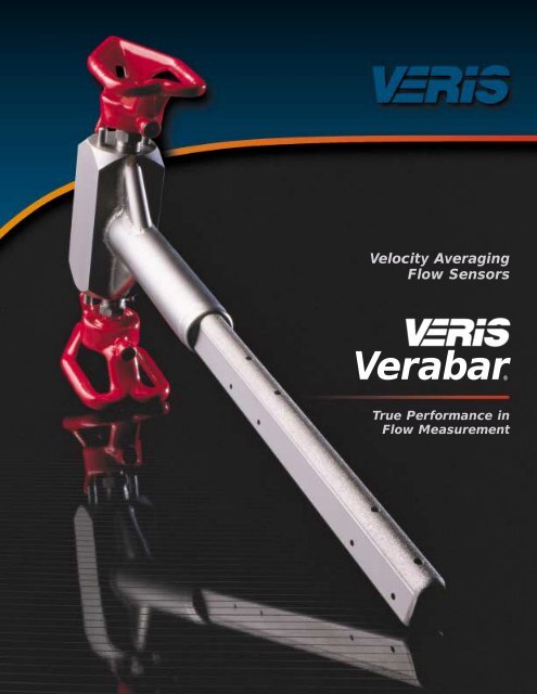
Velocity Averaging<br />
Flow Sensors<br />
<strong>Verabar</strong>®<br />
True Performance in<br />
Flow Measurement
From <strong>Veris</strong> Research…True Performance in DP Flow Measurement<br />
The Most Accurate and Reliable<br />
Technology for Measuring Gas, Liquid<br />
and Steam<br />
Developed from aerospace technology, the<br />
<strong>Verabar</strong> averaging pitot flow sensor provides<br />
unsurpassed accuracy and reliability.<br />
With its solid one-piece construction<br />
and bullet shape, the <strong>Verabar</strong><br />
makes flow measurement<br />
clog-free and precise.<br />
The unique sensor shape<br />
reduces drag and flow<br />
induced vibration.<br />
And the location<br />
of the low<br />
pressure<br />
ports eliminates<br />
the<br />
potential for clogging<br />
and improves signal<br />
stability.<br />
Superior Signal Stability<br />
and Greater Resistance to Clogging<br />
Clogging can occur in low pressure ports located in or near the partial vacuum<br />
at the rear of the sensor. The <strong>Verabar</strong> design locates the low pressure ports<br />
on the sides of the sensor, forward of the fluid<br />
separation point and turbulent wake<br />
area. This virtually eliminates clogging<br />
and produces an extremely<br />
stable signal.<br />
Percent Deviation from the Published K<br />
In God We Trust…<br />
All Others Bring Data<br />
The unique and exclusive breakthrough<br />
in improved accuracy<br />
derived from the development of<br />
a verified theoretical model<br />
predicts the <strong>Verabar</strong> flow<br />
coefficients. This eliminates<br />
the need for<br />
calibration tests to<br />
characterize the<br />
flow coefficients.<br />
3%<br />
2%<br />
1%<br />
0%<br />
-1%<br />
-2%<br />
Air Tests<br />
Water Tests<br />
0.5 Percent<br />
Error Band<br />
Without such a model,<br />
the uncertainty of the flow<br />
coefficients is dramatically<br />
increased and expensive<br />
calibration may be required.<br />
Empirical test data from independent<br />
laboratories verified the theoretical<br />
model and flow coefficients as a<br />
constant, independent of Reynolds number<br />
and within ±0.5% of the predicted value. The<br />
derivation of the theoretical model and test data<br />
is published in the <strong>Verabar</strong> Flow Test Report (ED-100).<br />
Test Data Summary<br />
± 1 /2 Percent<br />
-3%<br />
0% 5% 10% 15% 20% 25%<br />
Percent Blockage<br />
Rough Surface<br />
Smooth Surface<br />
Lower Drag and Extended Turndown<br />
Golf balls fly farther because they have a dimpled surface that<br />
lowers aerodynamic drag.<br />
The grooves and roughness on the <strong>Verabar</strong>’s frontal surface<br />
apply the same principle. This simple design feature relieves the<br />
partial vacuum at the rear of the sensor, reducing the pressure drag.<br />
This extends the accuracy and rangeability to very low velocities.
Unique Valve Head<br />
<strong>Verabar</strong> offers a new concept…<br />
built-in valves in the head of the<br />
instrument.<br />
This superior design:<br />
• Simplifies installation and<br />
maintenance.<br />
• Lowers the<br />
connecting<br />
hardware<br />
cost by<br />
reducing<br />
the number<br />
of fittings.<br />
Transmount<br />
A Transmount flow system<br />
is the first choice for all<br />
liquids; and for gas and<br />
steam applications, with<br />
slight variations in pressure<br />
and temperature.<br />
Mass<br />
Transmount<br />
A Mass Transmount flow<br />
system should be selected on<br />
steam and gas applications<br />
with variable temperature<br />
and pressure.<br />
Field Flow<br />
Systems<br />
Ready to install, the<br />
<strong>Verabar</strong> can be ordered<br />
with a manifold, transmitter<br />
or local indicating<br />
meter.<br />
Quick Jack<br />
Hot Tap<br />
Drive System<br />
Benefits of the Quick Jack<br />
Single Point Drive System:<br />
• Speeds sensor insertion<br />
and retraction.<br />
• Seals the drive threads<br />
from the environment<br />
and protects them from<br />
damage.<br />
• Removable, single point<br />
drive for use<br />
on multiple<br />
sensors.<br />
Complete<br />
Installation<br />
in Less than<br />
an Hour<br />
Spring-Lock…<br />
Offers a Superior Mounting<br />
Method<br />
This advanced, patented design ensures<br />
the sensor remains sealed, locked and<br />
pre-loaded to the opposite wall regardless<br />
of changes in pipe diameter due to pressure,<br />
temperature or mechanical force.<br />
This design has important advantages:<br />
• Fugitive emission and leak prevention…<br />
The Spring-Lock continually compensates<br />
for the differential in packing and<br />
body growth rates due to increased<br />
temperature.<br />
• Increases sensor strength,<br />
thereby eliminating the<br />
need for an opposite wall<br />
support. A locked, preloaded<br />
sensor is four<br />
times stronger than<br />
a non-preloaded,<br />
cantilevered sensor.<br />
• Other mounting methods<br />
do not pre-load the sensor<br />
or the packing seal and are subject to<br />
increased sensor vibration, metal fatigue,<br />
breakage and leakage.<br />
Spring-Lock<br />
Visual load<br />
indicator<br />
Compensates for<br />
changes in pipe<br />
diameter<br />
Spring<br />
travel<br />
The Proof of <strong>Verabar</strong> Accuracy<br />
Accurate Flow Coefficients<br />
The true test of a flow measurement device is its ability<br />
to repeat its published flow coefficient within its accuracy<br />
band.<br />
Actual Flow Test<br />
Test Location: Utah water Research Laboratory<br />
<strong>Verabar</strong><br />
Test Data: November 13, 1991<br />
Meter Size: 6 inch, Schd 40, -10<br />
Fluid: Water at 60 deg F<br />
Serial No: V1000.05.1<br />
has been<br />
0.74<br />
thoroughly<br />
.073<br />
tested at<br />
0.72<br />
0.71<br />
independent<br />
±1.0%<br />
K 0.70<br />
flow laboratories<br />
0.69<br />
(all sensor sizes, in<br />
0.68<br />
multiple pipe sizes,<br />
0.67<br />
in gas and liquids).<br />
0.66<br />
0 5 10 15 20 25<br />
Velocity (fps)
Fast and Easy Model Selection<br />
The easy-to-operate Veracalc computer program features:<br />
• Flow Calculations: DP from flow rate, or flow rate from DP.<br />
• Model Selection: Complete model selection from drop down menus.<br />
• Structural Analysis: Verifies sensor strength at flowing conditions.<br />
• Temperature and Pressure Limits: Error warnings if limits are exceeded.<br />
The Veracalc PC program is available from your local representative,<br />
the factory or it can be downloaded from our website at www.veris-inc.com.<br />
Regular Models — (Threaded Components)<br />
Model Number<br />
V100<br />
V110<br />
Hot Tap Models — (Threaded Components)<br />
V200 V250 V350<br />
<strong>Verabar</strong> Model Selector<br />
V150<br />
Hot Tap Models — (Flanged Components)<br />
Type of Mounting<br />
Tube Fitting<br />
V100 (Single Support)<br />
V110 (Double Support)<br />
Spring-Lock<br />
V150 (No opposite<br />
support required)<br />
Screw Drive<br />
V200<br />
Low Pressure<br />
Hand Insertion<br />
V250<br />
Quick Jack<br />
V350 (Removable)<br />
<strong>Verabar</strong> Applications<br />
The <strong>Verabar</strong> offers the widest application range<br />
of any flow sensor. It accurately measures gas, liquid<br />
and steam.<br />
Gas Liquid Steam<br />
Natural Gas Cooling/Chilled water Saturated<br />
Compressed Air Boiler Feed Water Superheated<br />
Combustion Air De-Mineralized Water Main Header<br />
Hydrocarbon Gas Hydrocarbon Liquids Custody Transfer<br />
Hot Air Cryogenic Distribution<br />
Blast Furnace Gas Thermal Transfer Fluids Energy Studies<br />
Extended Range Applications<br />
The <strong>Verabar</strong>’s versatile design lends itself to<br />
a wide range of applications. Contact <strong>Veris</strong><br />
application engineering for<br />
your special requirements.<br />
High Pressure Design<br />
2500# ANSI Class<br />
6000PSI and 1000ºF<br />
Model Number<br />
Type of Mounting<br />
V400<br />
V450<br />
Screw Drive<br />
V400<br />
Square and<br />
Rectangular Ducts<br />
Low Pressure<br />
Hand Insertion<br />
V450<br />
Large Stacks and Ducts<br />
Up to 21 feet<br />
(6 meters)<br />
Flanged Models — (Flanged Components)<br />
V500 V510 V550<br />
Flanged<br />
V500 (Single Support)<br />
V510 (Double Support)<br />
Flanged Spring-Lock<br />
V550 (No opposite<br />
support required)<br />
Specialized Mounting<br />
• PVC • Concrete<br />
• FRP • Cast Iron Pipe
Through Accuracy of Measurement, Low Installed and Operating Costs,<br />
<strong>Verabar</strong> Proves Its Performance, Efficiency and Value.<br />
<strong>Verabar</strong> Maintains Its<br />
Accuracy<br />
Orifice plates show long term<br />
deterioration of accuracy.<br />
The initial accuracy of the orifice<br />
plate is ±1%. However, long term<br />
accuracy deteriorates unless the plate<br />
is periodically inspected. Senior, dual<br />
chamber fittings are available to check<br />
the plate without requiring system<br />
shutdown, but such fittings are very<br />
expensive.<br />
Orifice Plate Test Results<br />
Florida Gas Transmission Company<br />
conducted a test to quantify various<br />
conditions which can result in inaccurate<br />
measurement. A partial list of the<br />
results is shown:<br />
Valve lubr. (-24%)<br />
Warpage (-9,6%)<br />
Wear (-13.1%)<br />
Dirt & grease (-11.1%)<br />
Leaks (-8.2%)<br />
Condition<br />
% Deviation<br />
Wear of knife edge:<br />
0.010” -2.2<br />
0.020” -4.5<br />
0.050” -13.1<br />
Dirt and grease<br />
deposits in pipe -11.1<br />
Valve lubrication upstream:<br />
one side of plate -15.8<br />
both sides -24.0<br />
Leaks around plate -8.2<br />
Plate warpage -9.6<br />
<strong>Verabar</strong> Lowers Installed<br />
Costs<br />
<strong>Verabar</strong> can save you more than 60%<br />
in installation costs over an orifice<br />
plate in a 10” pipe.<br />
The graph shows the total installed<br />
cost by pipe size of the orifice plate,<br />
the <strong>Verabar</strong>, and the resultant <strong>Verabar</strong><br />
savings. The most significant portion<br />
of the savings is the reduction in the<br />
linear inches of weld.<br />
Savings in Weld Time<br />
Only 4 inches<br />
of linear welding<br />
63 inches<br />
of linear welding<br />
Dollar<br />
Savings<br />
$ 100,000<br />
$ 50,000<br />
$ 10,000<br />
$ 5,000<br />
$ 1,000<br />
$ 500<br />
Installed Cost Savings<br />
Orifice<br />
Installed Cost<br />
<strong>Verabar</strong> Installed<br />
Cost Savings<br />
<strong>Verabar</strong> Installed Cost<br />
10 20 30 40 48<br />
Pipe Size (Inches)<br />
<strong>Verabar</strong> Has the Lowest<br />
Operating Costs<br />
<strong>Verabar</strong> pays for itself in less than<br />
a year.<br />
The graph shows the yearly operating<br />
cost savings and equivalent horsepower<br />
savings of the non-constricting, low<br />
permanent pressure loss <strong>Verabar</strong><br />
compared to the extremely constricting,<br />
high permanent pressure loss orifice<br />
plate. Savings are shown for gases,<br />
liquids and steam—at typical design<br />
velocities, by pipe size.<br />
<strong>Verabar</strong> vs. Orifice<br />
$<br />
$<br />
$ $ $<br />
$ $ $<br />
Dollar<br />
Savings<br />
$ 100,000<br />
$ 50,000<br />
$ 10,000<br />
$ 5,000<br />
$ 1,000<br />
$ 500<br />
Operating Cost Savings<br />
Air<br />
Liquids<br />
Steam<br />
Natural Gas<br />
10 20 30 40 48<br />
Pipe Size (Inches)<br />
Horsepower<br />
Savings @<br />
$ 0.05/KWH<br />
300<br />
200<br />
100<br />
50<br />
10<br />
5<br />
1
Quality Assurance<br />
<strong>Veris</strong> manufactures its own leak-proof,<br />
solid one-piece sensor. Our primary<br />
goal is to provide the highest quality<br />
and most accurate sensor in the<br />
industry.<br />
H L H L H L<br />
<strong>Verabar</strong> Round Diamond<br />
sensor sensor sensor<br />
Other manufacturers use a three-piece<br />
sensor design that has no positive<br />
mechanical method of maintaining<br />
a seal between the tubes. Therefore,<br />
temperature, pressure, vibration and<br />
even manufacturing variations can<br />
cause leakage between the chambers.<br />
This can result in a significant undetectable<br />
loss in accuracy.<br />
<strong>Verabar</strong> is designed to meet or exceed<br />
applicable ANSI and ASME codes.<br />
The <strong>Verabar</strong> is available to meet B31.1,<br />
B31.3, B31.8, NACE MR-01-75, etc.<br />
Additional QA capabilities include<br />
code welding, hydrostatic and other<br />
non-destructive testing.<br />
Why Average the Velocity<br />
Profile<br />
<strong>Verabar</strong> averages the velocity profile<br />
through multi-sensing ports which span<br />
the entire pipe diameter. Other types of<br />
non-averaging insert meters are SINGLE<br />
POINT INSERT METERS (turbine, vortex,<br />
magnetic, sonic, etc.). They assume a<br />
“textbook: turbulent velocity profile, and<br />
use a single “critical” point to infer an<br />
average velocity. In actual industrial applications,<br />
sensors are located downstream<br />
of disturbances, such as elbows or valves,<br />
which produce non-uniform velocity profiles.<br />
This makes it virtually impossible to<br />
locate a single point that represents the<br />
average velocity.<br />
Result: Inaccuracy ranging from ±10%<br />
to ±20%.<br />
⎫<br />
⎪⎬⎪⎭<br />
Textbook<br />
profile<br />
Elbow<br />
Actual profiles<br />
Control valve<br />
Low<br />
Reynolds<br />
Number<br />
Location of average velocity<br />
Other<br />
<strong>Verabar</strong><br />
Problems with Other Sensor Shapes<br />
Round Sensors<br />
Round sensors produce unpredictable<br />
accuracy. The original round sensors<br />
were designed for economical fluid<br />
balancing and did<br />
not meet industrial<br />
demands for<br />
accuracy. Round<br />
sensors have<br />
a variable fluid<br />
separation point<br />
that causes an<br />
unstable low<br />
pressure distribution<br />
around<br />
the sensor.<br />
Result:<br />
Inaccuracy in<br />
excess of ±5%<br />
and as high<br />
as ±10%.<br />
Flow<br />
Variable separation<br />
point<br />
Flow<br />
Diamond-Shaped Sensors<br />
These sensors produce pulsating, noisy<br />
signals. Diamond-shaped sensors<br />
improved accuracy by use of a sharp<br />
edge to fix the<br />
fluid’s separation<br />
point. However,<br />
this greatly<br />
amplified the<br />
vortex shedding<br />
forces.<br />
Result:<br />
The sharp<br />
edges generate<br />
extreme vortices,<br />
causing sensor<br />
vibration, pulsations<br />
and a noisy<br />
signal to the point<br />
that transmitter<br />
dampening and<br />
signal averaging<br />
are recommended.<br />
Flow<br />
Flow<br />
Fixed separation<br />
point<br />
H L H L<br />
Aerodynamic-Shaped Sensors<br />
Extreme aerodynamic shapes that<br />
permit the stream lines to reattach are<br />
subject to airfoil type lift forces. This<br />
occurs when<br />
the angle of Flow<br />
attack varies<br />
due to sensor<br />
misalignment,<br />
or the direction<br />
of the fluid<br />
varies, as is<br />
common in<br />
industrial piping<br />
with upstream<br />
disturbances.<br />
Result:<br />
The lift forces<br />
can cause an Flow<br />
unpredictable<br />
Lift forces<br />
shift in the low<br />
pressure distribution, producing<br />
inaccurate measurement.<br />
ISO 9001 Certified<br />
ISTEC CORPORATION<br />
5 Park Lake Road, Sparta, NJ 07871<br />
973 383 9888 (Phone)<br />
973 383 9088 (Fax)<br />
Email: sales@istec-corp.com<br />
Web: www.istec-corp.com