AXF magnetic flowmeter - Istec Corp.
AXF magnetic flowmeter - Istec Corp.
AXF magnetic flowmeter - Istec Corp.

Create successful ePaper yourself
Turn your PDF publications into a flip-book with our unique Google optimized e-Paper software.
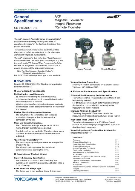
GeneralSpecificationsGS 01E20D01-01E<strong>AXF</strong>Magnetic FlowmeterIntegral Flowmeter/Remote FlowtubeThe <strong>AXF</strong> <strong>magnetic</strong> <strong>flowmeter</strong> series are sophisticatedproducts with outstanding reliability and ease ofoperation, developed on the basis of decades of fieldprovenexperience.The combination of a replaceable electrode and thediagnostic to defect adhesion level on the electrodesdramatically improves maintainability.The <strong>AXF</strong> employs the fluid noise free “Dual FrequencyExcitation Method” (for sizes up to 400 mm (16 in.)) andthe newly added “Enhanced Dual Frequency ExcitationMethod” as an option for more difficult applications toensure greater stability and quicker response.Note: The “Dual Frequency Excitation Method” isYokogawa’s unique technology.FOUNDATION Fieldbus protocol type is also available.Integral FlowmeterRemote Flowtube■ FEATURESRefer to GS 01E20F02-01E for Fieldbus communicationtype marked with “” User-oriented FunctionalityFluid Adhesion Level DiagnosisBy constantly monitoring the level of insulatingsubstance on the electrodes, it is possible to determinewhen maintenance is required.With the utilization of an optional replaceable electrode,the electrodes can be easily removed from the <strong>flowmeter</strong>and cleaned.Flexible Electrical Connection DirectionThe converter or the terminal box can be rotatedarbitrarily to change the directions of electricalconnection on the site.Clear and Versatile IndicationsThe LCD indicator employs a large, backlit full dotmatrix,that can facilitate various displays.One to three lines are available. When there is an alarmcondition, a full description of the countermeasure isindicated.“Easy Setup” Parameters “”The most frequently used parameters are arranged in agroup at the top.The infra-red switches enable the users to setparameters without opening the cover.● Expansion of Product LineupImproved Accuracy SpecificationThe standard accuracy is 0.35% of reading. Alsoavailable is an optional high accuracy calibration rated at0.2% of reading.Extra Small Size Flange TypeThe flange type is now available from a 2.5 mm size.Various Sanitary ConnectionsA variety of sanitary connections are available, such asTri-Clamp, ISO, DIN and SMS.● Enhanced Performance and SpecificationsEnhanced Dual Frequency Excitation MethodThe “Enhanced Dual Frequency Excitation Method” canbe optionally selected.For difficult applications such as for high concentrationslurries or low conductivity fluid, extremely stablemeasurements can be realized.Improved Minimum ConductivityThe newly designed <strong>AXF</strong> converter permits themeasurement of fluids with conductivity as low as 1µS/cm.High-Speed Pulse Output “”The pulse rate now goes up to 10,000 pps (pulse/second) for use with high speed applications such as inshort time batch processes.Versatile Input/ouput Function Now Available forIntegral Flowmeter “”CONTENTSFeatures P. 1Standard Specifications P. 2Hazardous Area Classification P.10Standard Performance P.14Normal Operating Conditions P.17Cautions for Installation P.21Inner Diameter of Grounding Ring P.22Accessories P.23Terminal Configuration and Terminal Wiring P.23Model and Suffix Code P.24Optional Specifications for Flowtubes P.31External Dimensions P.37Sizing Data P.55Recommended Gaskets between Flowtubes and User’sFlanges P.55Ordering Information P.56Yokogawa Electric <strong>Corp</strong>oration2-9-32, Nakacho, Musashino-shi, Tokyo, 180 JapanTel.: 81-422-52-4443 Fax.: 81-422-52-2018GS 01E20D01-01E©Copyright June 20037th Edition May 2006
■ STANDARD SPECIFICATIONS Converter (Integral <strong>flowmeter</strong>)*1: Select two points from: one pulse output, one alarmoutput, one status input, or two status outputs.*2: For models without an indicator, the hand-heldterminal is necessary to set parameters.Excitation Method:• Standard dual frequency excitation:Size 2.5 to 400 mm (0.1 to 16 in.)• Enhanced dual frequency excitation:Size 25 to 200 mm (1.0 to 8.0 in.)(Optional code HF1 or HF2)Input Signal (*1) “”:One Status Input: Dry contactLoad Resistance: 200 Ω or less (ON), 100 kΩ or more(OFF)Output Signals “”:• One Current Output: 4 to 20 mA DC (load resistance:750Ω maximum, including cable resistance)• One Pulse Output (*1):Transistor contact output (open collector)Contact capacity: 30 V DC (OFF), 200 mA (ON)Output rate: 0.0001 to 10,000 pps (pulse/second)• One Alarm Output (*1):Transistor contact output (open collector)Contact capacity: 30 V DC (OFF), 200 mA (ON)• Two Status Outputs (*1):Transistor contact output (open collector)Contact capacity: 30 V DC (OFF), 200 mA (ON)Communication Signals “”:BRAIN or HART communication signal(Superimposed on the 4 to 20 mA DC signal)Distance from Power Line: 15 cm (6 in.) or more(Parallel wiring should be avoided.)BRAIN:Communication Distance:Up to 2 km (1.25 miles), when polyethylene insulatedPVC-sheathed cables (CEV cables) are used.Communication distance varies depending on the typeof cable and wiring used.Load Resistance:250 to 600Ω (including cable resistance)Load Capacitance: 0.22 µF or lessLoad Inductance: 3.3 mH or lessInput Impedance of Communicating Device:10 kΩ or more (at 24 kHz)HART:Communication Distance:Up to 1.5 km (0.9 mile), when using multiple twistedpair cables. Communication distance varies dependingon the type of cable used.2Load Resistance:230 to 600Ω (including cable resistance)Cable Length for Specific Applications:Use the following formula to determine the cable lengthfor specific applications.L 65106(RC) (Cf10,000) Cwhere:L = length in meters or feetR = resistance in (including barrier resistance)C = cable capacitance in pF/m or pF/ftCf = maximum shunt capacitance of receiving devicesin pF/m or pF/ftNote: HART is a registered trademark of the HARTCommunication Foundation.Data Security During Power Failure:Data (parameters, totalizer value, etc.) storage byEEPROM. No back-up battery required.Indicator (*2):Full dot-matrix LCD (32132 pixels)Lightning Protector “”:The lightning protector is built into the current output andpulse/alarm/status input and output terminals. Whenoptional code A is selected, the lightning protector isbuilt into the power terminals.Protection:General-purpose Use/Sanitary Type/TIIS Flameprooftype:IP66, IP67, JIS C0920 immersion-proof typeExplosion proof type except TIIS:In case of explosion proof type except TIIS, refer todescription of "Enclosure" in "HAZARDOUS AREACLASSIFICATION".Coating:Case and Cover: Polyurethane corrosion-resistantCoating Color: Mint green coating (Munsell 5.6 BG3.3/2.9 or its equivalent)Converter Material:Case and Cover : Aluminum alloyMounting/Shapes (Integral Flowmeter):• Electrical Connection:ANSI 1/2 NPT femaleISO M20 1.5 femaleJIS G1/2 (PF1/2) female• Direction of Electrical Connection: The direction can bechanged even after delivery.• Terminal Connection: M4 size screw terminalGrounding:Grounding resistance 100 Ω or lessWhen optional code A is selected, grounding resistance10 Ω or less shall be applied.* In case of explosion proof type except TIIS, follow thedomestic electrical requirements as regulated in eachcountry.* In case of TIIS Flameproof type, refer to description of“HAZARDOUS AREA CLASSIFICATION”.All Rights Reserved. Copyright © 2003, Yokogawa Electric <strong>Corp</strong>oration GS 01E20D01-01E May 10,2006-00
Functions “”How to Set Parameters (*2):The indicator’s LCD and three infra-red switchesenable users to set parameters without opening thecase cover. Parameters can also be set by means ofthe HHT (Handheld terminal).Displayed Languages (*2):Users can choose a language from among English,Japanese, German, French, Italian, and Spanish.Instantaneous Flow Rate/Totalized Value DisplayFunctions (for models with an indicator) (*2):The full dot-matrix LCD enables user selections ofdisplays from one line to three lines for:• Instantaneous flow rate• Instantaneous flow rate (%)• Instantaneous flow rate (bar graph)• Current output value (mA)• Totalized value• Tag No.• Results of electrode adhesion diagnosticsTotalizer Display Function (*2):The flow rate is counted one pulse at a time according tothe setting of totalization pulse weights. For forward andreverse flow measurement functions, the totalizedvalues of the flow direction (forward or reverse) and theflow direction are displayed on the indicator togetherwith the units. The difference of totalized values betweenthe forward and reverse flow rate can be displayed.Totalization for the reverse flow rate is carried out onlywhen “Forward and reverse flow measurement functions”is selected.Damping Time Constant (*2):Time constant can be set from 0.1 second to 200.0seconds (63% response).Span Setting Function (*2):Span flows can be set in units such as volume flow rate,mass flow rate, time, or flow rate value. The velocity unitcan also be set.Volume Flow Rate Unit: kcf, cf, mcf, Mgal (US), kgal(US), gal (US), mgal (US), kbbl (US)*, bbl(US)*, mbbl (US)*, µbbl (US)*, Ml(megaliter), m 3 , kl (kiloliter), l (liter), cm 3Mass Flow Rate Unit (Density must be set.): klb (US), lb(US), t (ton), kg, gVelocity Unit: ft, m (meter)Time Unit: s (sec), min, h (hour), d (day)* “US oil” or “US Beer” can be selected.Pulse Output (*1)(*2):Scaled pulse can be output by setting a pulse weight.Pulse Width: Duty 50% or fixed pulse width (0.05, 0.1,0.5, 1, 20, 33, 50, 100 ms) can be selected.Output Rate: 0.0001 to 10,000 pps (pulse/second)3Multi-range Function (*1)(*2):• Range switching via status inputStatus input enables the switching of up to two ranges.• Automatic range switchingWhen the flow rate exceeds 100 % of the range,transition to the next range (up to four ranges) iscarried out automatically. Range swiching can beconfirmed by status outputs and indicator.Forward and Reverse Flow Measurement Functions (*1)(*2):Flows in both forward and reverse directions can bemeasured. The reverse flow measurement can beconfirmed by status output and indicator.Totalization Switch (*1)(*2):The status output is carried out when a totalized valuebecomes equal to or greater than the set value.Preset Totalization (*1)(*2):The parameter setting or status input enables a totalizedvalue to be preset to a setting value or zero.0% Signal Lock (*1)(*2):Status input forcibly fixes the instantaneous flow ratedisplay, current output, pulse output, and flow ratetotalization to 0%.Alarm Selection Function (*2):Alarms are classified into the System Alarms (hardfailures), Process Alarms (such as ‘Empty Pipe’, ‘SignalOverflow’ and ‘Adhesion Alarm’), Setting Alarms, andWarnings.Whether alarms should be generated or not can beselected for each item.The current output generated for an alarm can beselected from among 2.4 mA or less, fixed to 4 mA, 21.6mA or more, or HOLD.Alarm Output (*1)(*2):Alarms are generated only for the items selected via the‘Alarm Selection Function’ if relevant failures occur.Self Diagnostics Functions (*2):If alarms are generated, details of the System Alarms,Process Alarms, Setting Alarms and Warnings aredisplayed together with concrete descriptions ofcountermeasures.Flow Upper/Lower Limit Alarms (*1)(*2):If a flow rate becomes greater or smaller than the setvalue, this alarm is generated. In addition, two upperlimits (H, HH) and two lower limits (L, LL) can be set.If a flow rate becomes greater or smaller than any of theset values, the status is output.Electrode Adhesion Diagnostics Function (*1) (*2):This function enables monitoring of the adhesion level ofinsulating substances to the electrodes. Depending onthe status of adhesion, users are notified by a warning oran alarm via status outputs. If replaceable electrodes areused, they can be removed and cleaned when adhesionoccurs.All Rights Reserved. Copyright © 2003, Yokogawa Electric <strong>Corp</strong>oration GS 01E20D01-01E May 10,2006-00
4 Flowtubes (Remote Flowtube/Integral Flowmeter)Size of <strong>AXF</strong> Flowtubes: <strong>AXF</strong> Standard (Lay length code 1)Use Process Connection Lining Remote Flowtube Integral FlowmeterGeneralpurposeUseWaferFlangePFAPolyurethaneRubberNatural SoftRubberEPDMRubberCeramics(*1)PFAPolyurethaneRubberNatural SoftRubberEPDMRubber2.5 (0.1), 5 (0.2), 10 (0.4), 15 (0.5),25 (1.0), 32 (1.25), 40 (1.5), 50 (2.0),65 (2.5), 80 (3.0), 100 (4.0), 125 (5.0),150 (6.0), 200 (8.0), 250 (10), 300 (12)25 (1.0), 32 (1.25), 40 (1.5), 50 (2.0),65 (2.5), 80 (3.0), 100 (4.0), 125 (5.0),150 (6.0), 200 (8.0), 250 (10), 300 (12)50 (2.0), 65 (2.5), 80 (3.0), 100 (4.0),125 (5.0), 150 (6.0), 200 (8.0), 250 (10),300 (12)50 (2.0), 65 (2.5), 80 (3.0), 100 (4.0),125 (5.0), 150 (6.0), 200 (8.0), 250 (10),300 (12)15 (0.5), 25 (1.0), 40 (1.5), 50 (2.0),80 (3.0), 100 (4.0), 150 (6.0), 200 (8.0)2.5 (0.1), 5 (0.2), 10 (0.4), 15 (0.5), 25 (1.0),32 (1.25), 40 (1.5), 50 (2.0), 65 (2.5),80 (3.0), 100 (4.0), 125 (5.0), 150 (6.0),200 (8.0), 250 (10), 300 (12), 350 (14),400 (16)25 (1.0), 32 (1.25),40 (1.5), 50 (2.0),65 (2.5), 80 (3.0),100 (4.0), 125 (5.0),150 (6.0), 200 (8.0),250 (10), 300 (12),350 (14), 400 (16),500(20), 600 (24),700 (28), 800 (32),900(36), 1000(40),1100(44), 1200(48),1350(54), 1500(60),1600(64), 1800(72),2000(80), 2200(88),2400(96),2600(104)25 (1.0), 32 (1.25),40 (1.5), 50 (2.0),65 (2.5), 80 (3.0),100 (4.0), 125 (5.0),150 (6.0), 200 (8.0),250 (10), 300 (12),350 (14), 400 (16),50 (2.0), 65 (2.5), 80 (3.0), 100 (4.0),125 (5.0), 150 (6.0), 200 (8.0), 250 (10),300 (12), 350(14), 400(16)50 (2.0), 65 (2.5), 80 (3.0), 100 (4.0),125 (5.0), 150 (6.0), 200 (8.0), 250 (10),300 (12), 350(14), 400(16)High GradeAccuracy 0.2% ofRate (*3)25 (1.0), 32 (1.25),40 (1.5), 50 (2.0),65 (2.5), 80 (3.0),100 (4.0), 125 (5.0),150 (6.0), 200 (8.0)——25 (1.0), 32 (1.25),40 (1.5), 50 (2.0),65 (2.5), 80 (3.0),100 (4.0), 125 (5.0),150 (6.0), 200 (8.0)—Enhanced Dual FrequencyExcitation(Optional code HF1,HF2) (*3)25 (1.0), 32 (1.25),40 (1.5), 50 (2.0), 65 (2.5),80 (3.0), 100 (4.0), 125 (5.0),150 (6.0), 200 (8.0)25 (1.0), 32 (1.25), 40 (1.5),50 (2.0), 65 (2.5), 80 (3.0),100 (4.0), 125 (5.0), 150 (6.0),200 (8.0)50 (2.0), 65 (2.5),80 (3.0), 100 (4.0),125 (5.0), 150 (6.0),200 (8.0)50 (2.0), 65 (2.5),80 (3.0), 100 (4.0),125 (5.0), 150 (6.0),200 (8.0)25 (1.0), 32 (1.25), 40 (1.5),50 (2.0), 65 (2.5), 80 (3.0),100 (4.0), 125 (5.0),150 (6.0), 200 (8.0)25 (1.0), 32 (1.25), 40 (1.5),50 (2.0), 65 (2.5), 80 (3.0),100 (4.0), 125 (5.0),150 (6.0), 200 (8.0)Replaceable Electrode(Electrode structure code 2)25 (1.0), 32 (1.25), 40 (1.5),50 (2.0), 65 (2.5), 80 (3.0),100 (4.0), 125 (5.0), 150 (6.0),200 (8.0), 250 (10), 300 (12)25 (1.0), 32 (1.25), 40 (1.5),50 (2.0), 65 (2.5), 80 (3.0),100 (4.0), 125 (5.0), 150 (6.0),200 (8.0), 250 (10), 300 (12)—25 (1.0), 32 (1.25), 40 (1.5),50 (2.0), 65 (2.5), 80 (3.0),100 (4.0), 125 (5.0), 150 (6.0),200 (8.0), 250 (10), 300 (12),350 (14), 400 (16)25 (1.0), 32 (1.25), 40 (1.5),50 (2.0), 65 (2.5), 80 (3.0),100 (4.0), 125 (5.0), 150 (6.0),200 (8.0), 250 (10), 300 (12),350 (14), 400 (16)Union Joint Ceramics (*2) 2.5 (0.1), 5 (0.2), 10 (0.4) — — ——25 (1.0), 40 (1.5),50 (2.0), 80 (3.0),100 (4.0), 150 (6.0),200 (8.0)——25 (1.0), 40 (1.5), 50 (2.0),80 (3.0), 100 (4.0), 150 (6.0),200 (8.0)50 (2.0), 65 (2.5),80 (3.0), 100 (4.0),125 (5.0), 150 (6.0),200 (8.0)50 (2.0), 65 (2.5),80 (3.0), 100 (4.0),125 (5.0), 150 (6.0),200 (8.0)Unit: mm (in.)————All Rights Reserved. Copyright © 2003, Yokogawa Electric <strong>Corp</strong>oration GS 01E20D01-01E May 10,2006-00
5Size of <strong>AXF</strong> Flowtubes: <strong>AXF</strong> Standard (Lay length code 1) (continued)Use Process Connection Lining Remote Flowtube Integral FlowmeterSubmersibleTypeExplosionproof TypeSanitary TypeWaferFlangeWaferFlangeClamp:Tri-Clamp (*4),DIN32676ISO2852/SMS3016Union:DIN11851ISO2853 (*5)SMS1145 (*6)Butt Weld:DIN11850, ISO203PFAPolyurethaneRubberNatural SoftRubberEPDMRubberPFAPolyurethaneRubberNatural SoftRubberEPDMRubberPFACeramics(*1)PFAPFA15 (0.5), 25 (1.0),32 (1.25), 40 (1.5)50 (2.0), 65 (2.5),80 (3.0), 100 (4.0),125 (5.0), 150 (6.0),200 (8.0), 250 (10),300 (12)25 (1.0), 32 (1.25),40 (1.5), 50 (2.0),65 (2.5), 80 (3.0),100 (4.0), 125 (5.0),150 (6.0), 200 (8.0),250 (10), 300 (12)50 (2.0), 65 (2.5),80 (3.0),100 (4.0),125 (5.0),150 (6.0), 200 (8.0),250 (10), 300 (12)50 (2.0), 65 (2.5),80 (3.0),100 (4.0), 125 (5.0),150 (6.0), 200 (8.0),250 (10), 300 (12)15 (0.5), 25 (1.0),32 (1.25), 40 (1.5),50 (2.0), 65 (2.5),80 (3.0), 100 (4.0),125 (5.0), 150 (6.0),200 (8.0), 250 (10),300 (12), 350 (14),400 (16)25 (1.0), 32 (1.25),40 (1.5), 50 (2.0),65 (2.5), 80 (3.0),100 (4.0), 125 (5.0),150 (6.0), 200 (8.0),250 (10), 300 (12),350 (14), 400 (16),500(20), 600 (24),700 (28), 800 (32),900(36), 1000(40),1100(44), 1200(48),1350(54), 1500(60),1600(64), 1800(72),2000(80), 2200(88),2400(96),2600(104)50 (2.0), 65 (2.5), 80(3.0),100 (4.0), 125 (5.0),150 (6.0), 200 (8.0), 250 (10),300 (12), 350 (14), 400 (16)50 (2.0), 65 (2.5), 80(3.0),100 (4.0), 125 (5.0),—150 (6.0), 200 (8.0), 250 (10),300 (12), 350 (14), 400 (16)2.5 (0.1), 5 (0.2), 10 (0.4), 15 (0.5), 25 (1.0),32 (1.25), 40 (1.5), 50 (2.0), 65 (2.5),80 (3.0), 100 (4.0), 125 (5.0), 150 (6.0),200 (8.0), 250 (10), 300 (12)15 (0.5), 25 (1.0), 40 (1.5), 50 (2.0),80 (3.0), 100 (4.0), 150 (6.0), 200 (8.0)2.5 (0.1), 5 (0.2), 10 (0.4), 15 (0.5),25 (1.0), 32 (1.25), 40 (1.5), 50 (2.0),65 (2.5), 80 (3.0), 100 (4.0), 125 (5.0),150 (6.0), 200 (8.0), 250 (10), 300 (12),350 (14), 400 (16)15 (0.5), 25 (1.0), 32 (1.25), 40 (1.5),50 (2.0), 65 (2.5), 80 (3.0), 100 (4.0),125 (5.0)—25 (1.0), 32 (1.25),40 (1.5), 50 (2.0),65 (2.5), 80 (3.0),100 (4.0), 125 (5.0),150 (6.0), 200 (8.0)— ——25 (1.0), 32 (1.25),40 (1.5), 50 (2.0),65 (2.5), 80 (3.0),100 (4.0), 125 (5.0),150 (6.0), 200 (8.0)— —25 (1.0), 32 (1.25),40 (1.5), 50 (2.0),65 (2.5), 80 (3.0),100 (4.0), 125 (5.0),150 (6.0), 200 (8.0)25 (1.0), 40 (1.5),50 (2.0), 80 (3.0),100 (4.0), 150 (6.0),200 (8.0)25 (1.0), 32 (1.25),40 (1.5), 50 (2.0),65 (2.5), 80 (3.0),100 (4.0), 125 (5.0),150 (6.0), 200 (8.0)25 (1.0), 32 (1.25), 40 (1.5),50 (2.0), 65 (2.5), 80 (3.0),100 (4.0), 125 (5.0),150 (6.0), 200 (8.0) —25 (1.0), 32 (1.25), 40 (1.5),50 (2.0), 65 (2.5), 80 (3.0),100 (4.0), 125 (5.0),150 (6.0), 200 (8.0)25 (1.0), 32 (1.25), 40 (1.5),50 (2.0), 65 (2.5), 80 (3.0),100 (4.0), 125 (5.0),150 (6.0), 200 (8.0)25 (1.0), 32 (1.25),40 (1.5), 50 (2.0), 65 (2.5),80 (3.0), 100 (4.0),125 (5.0), 150 (6.0),200 (8.0)50 (2.0), 65 (2.5),80 (3.0), 100 (4.0),125 (5.0), 150 (6.0),200 (8.0)50 (2.0), 65 (2.5),80 (3.0), 100 (4.0),125 (5.0), 150 (6.0),200 (8.0)25 (1.0), 32 (1.25), 40 (1.5),50 (2.0), 65 (2.5), 80 (3.0),100 (4.0), 125 (5.0),150 (6.0), 200 (8.0)25(1.0),40(1.5),50(2.0),80(3.0),100(4.0),150(6.0),200(8.0)25 (1.0), 32 (1.25), 40 (1.5),50 (2.0), 65 (2.5), 80 (3.0),100 (4.0), 125 (5.0),150 (6.0), 200 (8.0)Union Joint Ceramics (*2) 2.5 (0.1), 5 (0.2), 10 (0.4) — — —25 (1.0), 32 (1.25), 25 (1.0), 32 (1.25),40 (1.5), 50 (2.0), 40 (1.5), 50 (2.0),65 (2.5), 80 (3.0), 65 (2.5), 80 (3.0),100 (4.0), 125 (5.0) 100 (4.0), 125 (5.0)*1: <strong>AXF</strong> standard lay length dimensions for wafer type ceramics linings are the same as those for ADMAG ceramics linings.*2: <strong>AXF</strong> standard lay length dimensions for union joint type ceramics linings are the same as those for ADMAG ceramics linings.*3: Enhanced dual frequency excitation is not available for models with High grade accuracy.*4: Not available with 32 mm (1.25 in.), 125 mm (5.0 in.)*5: Not available with 125 mm (5.0 in.)*6: Not available with 15 mm (0.5 in.), 125 mm (5.0 in.)———High GradeAccuracy 0.2% ofRate (*3)————Enhanced Dual FrequencyExcitation(Optional code HF1,HF2) (*3)50 (2.0), 65 (2.5),80 (3.0), 100 (4.0),125 (5.0), 150 (6.0),200 (8.0)50 (2.0), 65 (2.5),80 (3.0), 100 (4.0),125 (5.0), 150 (6.0),200 (8.0)Unit: mm (in.)Replaceable Electrode(Electrode structure code 2)———————————T21.EPSAll Rights Reserved. Copyright © 2003, Yokogawa Electric <strong>Corp</strong>oration GS 01E20D01-01E May 10,2006-00
6Size of <strong>AXF</strong> Flowtubes: Replacement model for earlier ADMAG or ADMAG AE (Lay length code 2)Use Process Connection Lining Remote Flowtube Integral FlowmeterGeneralpurposeuseSubmersibleTypeWafer (*6)Flange (*7)Wafer (*6)Flange (*7)PFAPolyurethanerubberPFAPolyurethanerubberPFAPolyurethanerubberPFAPolyurethanerubber2.5 (0.1), 5 (0.2), 10 (0.4), 15 (0.5),25 (1.0), 40 (1.5), 50 (2.0), 80 (3.0),100 (4.0), 150 (6.0), 200 (8.0)25 (1.0), 40 (1.5), 50 (2.0), 80 (3.0),100(4.0), 150 (6.0), 200(8.0)150 (6.0), 200 (8.0), 250 (10)150 (6.0), 200 (8.0), 250 (10)15 (0.5), 25 (1.0),40 (1.5), 50 (2.0),80 (3.0), 100 (4.0),150 (6.0), 200 (8.0)25 (1.0), 40 (1.5),50 (2.0), 80 (3.0),100 (4.0), 150 (6.0),200 (8.0)150 (6.0), 200 (8.0),250(10)150 (6.0), 200 (8.0),250 (10)————High GradeAccuracy 0.2% ofRateEnhanced Dual FrequencyExcitation(Optional code HF1,HF2)Unit: mm (in.)Replaceable Electrode(Electrode structure code 2)—25 (1.0), 40 (1.5), 50 (2.0),80 (3.0), 100 (4.0),150 (6.0), 200 (8.0)——25 (1.0), 40(1.5), 50 (2.0),80(3.0), 100 (4.0),—150 (6.0), 200 (8.0)— 150 (6.0), 200 (8.0) 150 (6.0), 200 (8.0), 250 (10)— 150 (6.0), 200 (8.0) 150 (6.0), 200 (8.0), 250 (10)————25 (1.0), 40 (1.5),50 (2.0), 80 (3.0), 100 (4.0),150 (6.0), 200 (8.0)25 (1.0), 40 (1.5), 50 (2.0),80 (3.0), 100 (4.0),150 (6.0), 200 (8.0)150 (6.0), 200 (8.0)150 (6.0), 200 (8.0)Explosion Wafer (*6) PFA2.5 (0.1), 5 (0.2), 10 (0.4), 15 (0.5),25 (1.0), 40 (1.5), 50 (2.0), 80 (3.0),—25 (1.0), 40 (1.5), 50 (2.0),80 (3.0), 100 (4.0),—proof Type100 (4.0), 150 (6.0), 200 (8.0)150 (6.0), 200 (8.0)Flange (*7) PFA 150 (6.0), 200 (8.0), 250 (10)— 150 (6.0), 200 (8.0) —T22.EPS*6: ADMAG lay length dimensions for wafer type of 250 mm (10 in.), and 300 mm (12 in.) are the same as those for <strong>AXF</strong> Standard.And, in case of “platinum-iridium (grounding ring code P) or tantalum (grounding ring code T) or None (grounding ring code N)” in wafer type of 2.5 mm (0.1 in.)to 15 mm (0.5 in.), the lay lengths of Replacement model are the same as those for <strong>AXF</strong> Standard.*7: ADMAG lay length dimensions for flange type of 15 mm (0.5 in.) to 100 mm (4.0 in.), or 300 mm (12 in.) to 2600 mm (104 in.) are the same as those for <strong>AXF</strong>Standard. However, in case of platinum-iridium (grounding ring code P) or tantalum (grounding ring code T) or None (grounding ring code N) in flange type of 15mm (0.5 in.) to 100 mm (4.0 in.), the lay length of <strong>AXF</strong> Standard are longer by approx. 4mm (0.16 in) than those of earlier ADMAG or ADMAG AE.————Protection:General-Purpose Use/Sanitary Type/TIIS FlameproofType:IP66, IP67, JIS C0920 immersion-proof typeExplosion proof type except TIIS:In case of explosion proof type except TIIS, refer todescription of “Enclosure” in “HAZARDOUS AREACLASSIFICATION”.Submersible Type (only for Remote Flowtube):IP68 (can be used for temporary submergence)JIS C0920 Submersible TypeNote: Test Condition: 50 m below the surface of thewater, equivalent to 0.5 MPa hydraulic pressure,for one month.Cable should be protected at customer site. In thecase of installation always under water orcorrosion fluid, contact Yokogawa office.Coating:General-Purpose Use/Explosion proof Type:Size 2.5 to 125 mm (0.1 to 5.0 in.) (Wafer type),Size 2.5 to 125 mm (0.1 to 5.0 in.) (Process connectioncode B or D of flange type):· Housing: No coating (Stainless steel surface)· Flange (Flange type only) : No coating (Stainlesssteel surface)· Terminal Box and Cover (Remote Flowtube):Polyurethane corrosion-resistant coatingCoating color: Mint green (Munsell 5.6 BG 3.3/2.9or its equivalent)Size 150 to 300 mm (6.0 to 12 in.) (Wafer type),Size 150 to 400 mm (6.0 to 16 in.) (Process connectioncode B of flange type),Size 50 to 2600 mm (2.0 to 104 in.) (Process connectioncode C of flange type):· Housing, Flange (Flange type only), Terminal Boxand Cover (Remote Flowtube):Polyurethane corrosion-resistant coatingCoating color: Mint green (Munsell 5.6 BG 3.3/2.9or its equivalent)Sanitary Type:Size 15 to 125 mm (0.5 to 5.0 in.):· Housing: No coating (Stainless steel surface)· Adapter : No coating (Stainless steel surface)· Terminal Box and Cover (Remote Flowtube):Polyurethane corrosion-resistant coatingCoating color: Mint green (Munsell 5.6 BG 3.3/2.9or its equivalent)Submersible Type: Non-tar epoxy coating (black)All Rights Reserved. Copyright © 2003, Yokogawa Electric <strong>Corp</strong>oration GS 01E20D01-01E May 10,2006-00
Flowtube Material:Size 2.5 mm (0.1 in.) to 15 mm (0.5 in.)Mini-FlangePipePart NameHousingFlangeWafer TypePFA/PolyurethaneRubber liningWafer TypeCeramics lining [onlyfor 15 mm (0.5 in.)]Sanitary Type[only for 15 mm (0.5 in.)]Wafer TypePFA/PolyurethaneRubber liningWafer Type/Union JointCeramics liningFlange TypePFA liningSanitary Type[only for 15 mm (0.5 in.)]Terminal Box (Remote Flowtube)MaterialStainless steel-JIS SCS11Stainless steel-JIS SUS304or SUSF304 (AISI 304SS/EN 1.4301 equivalent)Stainless steel-JIS SCS13(EN 1.4308 equivalent)Stainless steel-JISSUS316L (AISI 316SS/EN 1.4404 equivalent)Stainless steel-JIS SCS13(EN 1.4308 equivalent)Stainless steel-JIS SCS13(EN 1.4308 equivalent)Alumina ceramics (99.9%)Stainless steel-JIS SCS13(EN 1.4308 equivalent)and SUS304 (AISI 304SS/EN 1.4301 equivalent)Stainless steel-JIS SCS13(EN 1.4308 equivalent)Aluminum alloyT03.EPSSize 25 mm (1.0 in.) to 125 mm (5.0 in.)FlangeMini-FlangePipePart NameHousingProcess Connection code: B**Process Connection code: C**[(Size 50 mm (2.0 in.) to 125 mm (5.0 in.)]Wafer TypePFA/Polyurethane Rubber/Natural Soft Rubber/EPDM Rubber liningWafer TypeCeramics liningSanitary TypeWafer TypePFA/PolyurethaneRubber/Natural Soft Rubber/EPDM Rubber liningFlange TypePFA/PolyurethaneRubber/Natural Soft Rubber/EPDM Rubber liningWafer TypeCeramics liningSanitary TypeTerminal Box (Remote Flowtube)Size25 mm (1.0 in.)(Lay Length code 1)Size25 mm (1.0 in.)(Lay Length code 2)Size32 mm (1.25 in.) to125 mm (5.0 in.)Size25 mm (1.0 in.) to50 mm (2.0 in.)Size80 mm (3.0 in.),100 mm (4.0 in.)Size25 mm (1.0 in.)Size32 mm (1.25 in.) to125 mm (5.0 in.)Size25 mm (1.0 in.)(Lay Length code 1)Size25 mm (1.0 in.)(Lay Length code 2)Size32 mm (1.25 in.) to125 mm (5.0 in.)Size25 mm (1.0 in.)Size32 mm (1.25 in.) to125 mm (5.0 in.)Size25 mm (1.0 in.) to100 mm (4.0 in.)Size25 mm (1.0 in.)Size32 mm (1.25 in.) to125 mm (5.0 in.)MaterialStainless steel-JIS SUS304(AISI 304 SS/EN 1.4301equivalent)Stainless steel-JIS SUS304or SUSF304 (AISI 304SS/EN 1.4301 equivalent)Carbon steel-JIS SS400Stainless steel- EN 1.4308(SCS13 equivalent)Stainless steel-JIS SUS430(ASTM 43000/DINX6Cr17/EN 1.4016equivalent)Stainless steel-JIS SUS430(ASTM 43000/DINX6Cr17/EN 1.4016equivalent)Stainless steel-JIS SCS13(EN 1.4308 equivalent)Stainless steel-JIS SUS304(AISI 304 SS/EN 1.4301equivalent)Stainless steel- EN 1.4308(SCS13 equivalent)Alumina ceramics (99.9%)Aluminum alloy7Stainless steel-JISSUS316L (AISI 316L SS/EN1.4404 equivalent)Stainless steel-JIS SUS304(AISI 304 SS/EN 1.4301equivalent)Stainless steel-JIS SUS304(AISI 304 SS/EN 1.4301equivalent)Stainless steel-JIS SUS304(AISI 304 SS/EN 1.4301equivalent)Stainless steel- EN 1.4308(SCS13 equivalent)Stainless steel-JIS SUS304(AISI 304 SS/EN 1.4301equivalent)Stainless steel-JIS SCS13(EN 1.4308 equivalent)Stainless steel-JIS SUS304(AISI 304 SS/EN 1.4301equivalent)T04.EPSAll Rights Reserved. Copyright © 2003, Yokogawa Electric <strong>Corp</strong>oration GS 01E20D01-01E May 10,2006-00
Size 150 mm (6.0 in.) to 400 mm (16 in.)FlangeMini-FlangePipePart NameHousingProcess Connection code: B**Process Connection code: C**Wafer TypePFA/Polyurethane Rubber/Natural Soft Rubber/EPDM Rubber liningWafer TypeCeramics lining [available with150 mm (6.0 in.), 200 mm (8.0 in.)]Flange Type/Wafer TypePFA/Polyurethane Rubber/Natural Soft Rubber/EPDM Rubber liningWafer TypeCeramics lining [available with150 mm (6.0 in.), 200 mm (8.0 in.)]Terminal Box (Remote Flowtube)MaterialCarbon steel-JIS SPCCStainless steel-JIS SUS304or SUSF304 (AISI 304SS/EN 1.4301 equivalent)Carbon steel-JIS SS400Carbon steel-JIS SS400Stainless steel-JIS SUS304(AISI 304 SS/EN 1.4301equivalent)Stainless steel-JIS SUS304(AISI 304 SS/EN 1.4301equivalent)Alumina ceramics (99.9%)Aluminum alloySize 500 mm (20 in.) to 2600 mm (104 in.)Terminal Box(Remote Flowtube)Part NameHousingFlangePipeCase, Cover(500 to 1000 mm)(20 to 40 in.)Case(1100 to 2600 mm)(44 to 104 in.)Cover(1100 to 2600 mm)(44 to 104 in.)MaterialCarbon steel-JIS SPCCCarbon steel-JIS SS400T05.EPSStainless steel-JIS SUS304(AISI 304 SS/EN 1.4301equivalent)Aluminum alloyStainless steel-JIS SUS304(AISI 304 SS/EN 1.4301equivalent)Electrical connection:Carbon steelAluminum alloyT05-1.EPSGrounding Ring/Grounding Electrode:• Grounding Ring(plate type)Stainless steel-JIS SUS316 (AISI 316 SS/EN 1.4401equivalent),Stainless steel-JIS SUS316L (AISI 316L SS/EN1.4404 equivalent),Hastelloy*1 C276 equivalent, Titanium,Stainless steel-JIS SUS304 (AISI 304 SS/EN 1.4301equivalent) for size 500 to 1000mm (20 to 40 in.)only,SS400 carbon steel lined with stainless steel-JISSUS316 (AISI 316 SS/EN 1.4404 equivalent) for size1100 to 2600mm (44 to 104 in.) only.• Grounding Electrode(electrode type)Fluorocarbon PFA lining + grounding electrode(Tantalum, Platinum-Iridium)*1: Hastelloy is a registered trademark of HaynesInternational Inc.*2: Available with sizes 2.5 to 200mm (0.1 to 8.0 in.),PFA and ceramics linings only. However, thepermeable fluids (such as nitric acid, hydrofluoricacid, or sodium hydroxide at high temperature) areunusable.8Wetted Part Material:Lining:Fluorocarbon PFA*1 liningPolyurethane Rubber liningNatural Soft Rubber lining*2EPDM Rubber lining*3Alumina ceramics lining*1: PFA is FDA (U.S. Food and Drug Administration)approval material.*2: Natural soft rubber is a material which can reducewear of the lining due to fluids mixed with slurries.If the concentration of mixed slurries is high,contact Yokogawa as necessary measures need tobe taken separately for the electrodes.*3: EPDM rubber lining is superior in the ozone proof.Electrode:Stainless steel-JIS SUS316L (AISI 316L SS/EN 1.4404equivalent), Hastelloy*1 C276 equivalent, Titanium,Tantalum, Platinum-Iridium, Tungsten Carbide,Platinum-Alumina cermet(only for ceramics lining)Note : For size over 500 mm and sanitary type, SUS316Lonly.All Rights Reserved. Copyright © 2003, Yokogawa Electric <strong>Corp</strong>oration GS 01E20D01-01E May 10,2006-00
9Gasket:Joints:UseLiningGeneral-Purpose Use / Submersible Type /Explosion proof TypePFA/Polyurethane Rubber/Natural Soft Rubber/EPDM RubbergroundingringgroundingringCeramicsLiningStandardCeramicsUnion Joints (size 10 mm or less)weld joint(GUW)screw joint(GUN, GUR)nutGasket within FlowtubeStandardMaterials for Union JointNo gasket within FlowtubeGasket within FlowtubeGasket Material (within Flowtube)Fluororesin with—ceramic fillers(Valqua #7020)Process Connection CodeGUW: Union Joint (weld joint)Process Connection CodeGUN, GUR: union joint(screw joint)Stainless steel(JIS SUS316L(ANSI 316L SS/EN1.4404equivalent))groundingringgroundingringNote: Contact Yokogawa office if PVC union joint is required.T23-3.EPSOptional code(GA, GC,GD, or GF)Only whenselectingthe PFA lining/ceramics liningGasket within Flowtube Gasket within FlowtubeGasket Material (within Flowtube)GA: Fluororubber for PVC pipes (Viton®)GC: Acid-resistant fluororubber for PVC pipes (Viton®)GD: Alkali-resistant fluororubber for PVC pipes (Viton®)GF* 1 : Fluororesin with alkali-resistant carbons for metalpipes*1: GF is applicable only for ceramics lining.groundingringUseStandardAdapter for clampconnectionAdapter for unionconnectionAdapter for buttweld connectionSanitary TypeMaterials for Adapters (clamp, union, butt weld)Stainless steel-JIS SUS316L(AISI 316L SS/EN 1.4404 equivalent)Optional code(BCF, BSF,BCC, orBSC)UseLiningStandardFlange of user’spipeGasket for user’s flangeGasket Material (for user’s flange)BCF, BSF: PTFE-sheathed non-asbestosBCC, BSC: Chloroprene rubberAdapter for clampconnectionAdapter for unionconnectionSanitary TypePFAT23-1.EPSO-Ring (Replaceable electrode type only):Fluororubber (Part number : G9303SE)T23-4.EPSElectrode Construction:Non-replaceable Electrode TypeGeneral-Purpose Use/Submersible Type/Explosionproof Type:PFA, Polyurethane Rubber lining:External insertion typeNatural Soft Rubber, EPDM Rubber lining:Internal insertion typeCeramics lining: Integral typeSanitary Type: Internal insertion typeAdapter for buttweld connectionGasket within FlowtubeGasket Material (within Flowtube)EPDM (ethylene propylene) rubberOptional code(GH)GH: Silicone rubberT23-2.EPSAll Rights Reserved. Copyright © 2003, Yokogawa Electric <strong>Corp</strong>oration GS 01E20D01-01E May 10,2006-00
Replaceable Electrode TypeElectrode parts can be put into unit to facilitatereplacement or mounting at customer site.The optional dedicated tool (F9807SK) is required.Replaceable electrodes are available for thefollowing:<strong>AXF</strong> standard:UseGeneral-Purpose UseProcessConnectionWaferFlangeAvailableSize25 to 300 mm(1.0 to 12 in.)25 to 400 mm(1.0 to 16 in.)LiningPFA/PolyurethaneRubberElectrodeMaterialJIS SUS316L(AISI 316LSS/EN1.4404equivalent) ( * 1)T06.EPSReplacement model for earlier ADMAG or ADMAG AE:UseGeneral-Purpose UseProcessConnectionFlangeAvailableSize150 to 250 mm(6.0 to 10 in.)LiningPFA/PolyurethaneRubberElectrodeMaterialJIS SUS316L(AISI 316LSS/EN1.4404equivalent) ( * 1)T07.EPS*1: If any other electrode materials are required, pleasecontact Yokogawa office.Mounting/Shapes (Remote Flowtube):• Electrical Connection: ANSI 1/2 NPT femaleISO M20 1.5 femaleJIS G1/2 (PF1/2) female• Direction of Electrical Connection: The direction can bechanged even after delivery.Note: In case of submersible types, an optional codeDHC, and sizes of 1100 mm or larger, the directioncan not be changed after delivery.• Terminal Connection at Terminal Box: M4 size screwGrounding:Grounding resistance 100 Ω or less* In case of explosion proof type except TIIS, follow thedomestic electrical requirements as regulated in eachcountry.* In case of TIIS Flameproof type, refer to description of“HAZARDOUS AREA CLASSIFCATION”.Combined Converter:•A remote flowtube for sizes of up to 400 mm can becombined with the <strong>AXF</strong>A11 Converter or the <strong>AXF</strong>A14Converter. If a combined converter is changed from<strong>AXF</strong>A11 to <strong>AXF</strong>A14 or vice versa, a new meter factormust be adjusted by flow calibrations.• In case that size 250 mm (10 in.) or larger is used in lowconductivity or high concentration slurries, please usethe <strong>AXF</strong>A11 Converter.•A remote flowtube for sizes of 500 mm or larger can becombined with the <strong>AXF</strong>A11 Converter only.• Maximum Cable Length:Combination of <strong>AXF</strong> remote Flowtube and <strong>AXF</strong>A11:up to 200 m (660 ft)Combination of <strong>AXF</strong> remote Flowtube and <strong>AXF</strong>A14:up to 100 m (330 ft)10■ HAZARDOUS AREA CLASSIFICATIONFM:*<strong>AXF</strong>002C – <strong>AXF</strong>400CApplicable Standard:FM3600, FM3610, FM3615,FM3810, ANSI/NEMA 250(Integral Flowmeter)Explosion proof for Class I, Division 1, Groups A, B, C& D.Dust-ignition proof for Class II/III, Division1, Groups E,F & G.Intrinsically safe (electrodes) for Class I, Division 1,Groups A, B, C & D.“SEAL ALL CONDUITS WITHIN 18 INCHES”“WHEN INSTALLED IN DIV. 2, SEALS NOT REQUIRED”Electrode Circuit Um: 250 Vac/dcMaximum power supply voltage: 250 Vac/130 VdcExcitation Circuit: 140V maxEnclosure: NEMA 4XTemperature Code: T6Refer to following table;TemperatureCodeT6T5T4T3Maximum ProcessTemperature+70°C (+158°F)+85°C (+185°F)+120°C (+248°F)+130°C (+266°F)Minimum ProcessTemperature–40°C (–40°F)–40°C (–40°F)–40°C (–40°F)–40°C (–40°F)Ambient Temp.: –40°C to +60°C (–40°F to +140°F)T27-1_1.EPS(Remote Flowtube)Explosion proof for Class I, Division 1, Groups A, B, C& D.Dust-ignition proof for Class II/III, Division1, Groups E,F & G.Intrinsically safe (electrodes) for Class I, Division 1,Groups A, B, C & D.“SEAL ALL CONDUITS WITHIN 18 INCHES”“WHEN INSTALLED IN DIV. 2, SEALS NOT REQUIRED”Electrode Circuit Um: 250 Vac/dcExcitation Circuit: 170V maxEnclosure: NEMA 4XTemperature Code: T6Refer to following table;TemperatureCodeT6T5T4T3Maximum ProcessTemperature+70°C (+158°F)+85°C (+185°F)+120°C (+248°F)+150°C (+302°F)Minimum ProcessTemperature–40°C (–40°F)–40°C (–40°F)–40°C (–40°F)–40°C (–40°F)Ambient Temp.: –40°C to +60°C (–40°F to +140°F)Note: Installation shall be in accordance with themanufacturer’s instructions and National Electriccode, ANSI/NFPA-70.T28-1_1.EPSAll Rights Reserved. Copyright © 2003, Yokogawa Electric <strong>Corp</strong>oration GS 01E20D01-01E May 10,2006-00
CENELEC ATEX (KEMA):*<strong>AXF</strong>002C – <strong>AXF</strong>400CApplicable Standard:EN 50014, EN 50018, EN 50019,EN 50020, EN 50028, EN 50281-1-1,EN 60529, EN 61010-1Certificate: KEMA 03ATEX2435(Integral Flowmeter)CENELEC ATEX (KEMA) Flameproof TypeGroup: IICategory: 2GEEx dme[ia] IIC T6...T3Electrode Circuit Um: 250 Vac/dcMaximum power supply voltage: 250 Vac/130 VdcExcitation Circuit: 140V maxEnclosure: IP66, IP67Temperature Class:TemperatureClassT6T5T4T3Maximum ProcessTemperature+70°C (+158°F)+85°C (+185°F)+120°C (+248°F)+130°C (+266°F)Minimum ProcessTemperature–40°C (–40°F)–40°C (–40°F)–40°C (–40°F)–40°C (–40°F)Ambient Temp.: –40°C to +60°C (–40°F to +140°F)T27-2.EPSCENELEC ATEX (KEMA) Type of Protection “Dust”Group: IICategory: 1DElectrode Circuit Um: 250 Vac/dcMaximum power supply voltage: 250 Vac/130 VdcExcitation Circuit: 140V maxEnclosure: IP66, IP67Maximum surface temperature:(Remote Flowtube)CENELEC ATEX (KEMA) Flameproof TypeGroup: IICategory: 2GEEx dme[ia] IIC T6...T3Electrode Circuit Um: 250 Vac/dcExcitation Circuit: 170V maxEnclosure: IP66, IP67Temperature Class:TemperatureClassT6T5T4T3Maximum ProcessTemperature+70°C (+158°F)+85°C (+185°F)+120°C (+248°F)+150°C (+302°F)Minimum ProcessTemperature–40°C (–40°F)–40°C (–40°F)–40°C (–40°F)–40°C (–40°F)Ambient Temp.: –40°C to +60°C (–40°F to +140°F)11T28-2.EPSCENELEC ATEX (KEMA) Type of Protection “Dust”Group: IICategory: 1DElectrode Circuit Um: 250 Vac/dcExcitation Circuit: 170V maxEnclosure: IP66, IP67Maximum surface temperature:Maximum SurfaceTemperatureT75°C (+167°F)T85°C (+185°F)T100°C (+212°F)T115°C (+239°F)Maximum ProcessTemperature+70°C (+158°F)+85°C (+185°F)+120°C (+248°F)+150°C (+302°F)T30.EPSAmbient Temp.: –40°C to +60°C (–40°F to +140°F)Maximum SurfaceTemperatureT75°C (+167°F)T85°C (+185°F)T100°C (+212°F)Maximum ProcessTemperature+70°C (+158°F)+85°C (+185°F)+120°C (+248°F)T110°C (+230°F) +130°C (+266°F)T29.EPSAmbient Temp.: –40°C to +60°C (–40°F to +140°F)All Rights Reserved. Copyright © 2003, Yokogawa Electric <strong>Corp</strong>oration GS 01E20D01-01E May 10,2006-00
CSA:*<strong>AXF</strong>002C – <strong>AXF</strong>400CApplicable Standard:For CSA C22.2 Series;C22.2 No 0, C22.2 No 0.4, C22.2 No 0.5,C22.2 No 25, C22.2 No 30, C22.2 No 94,C22.2 No 157, C22.2 No 1010.1For CSA E79 Series;CAN/CSA-E79-0, CAN/CSA-E79-1,CAN/CSA-E79-7, CAN/CSA-E79-11,CAN/CSA-E79-18Certificate: 1481213(Integral Flowmeter)For CSA C22. 2 SeriesExplosion proof for Class I, Division 1, Groups A, B, C& D.Dust-ignition proof for Class II/III, Division 1, Groups E,F & G.Intrinsically safe (electrodes) for Class I, Division 1,Groups A, B, C & D.“SEAL ALL CONDUITS WITHIN 50 cm OF THEENCLOSURE”“WHEN INSTALLED IN DIV. 2, SEALS NOT REQUIRED”Electrode Circuit Um: 250 Vac/dcMaximum power supply voltage: 250 Vac/130 VdcExcitation Circuit: 140V maxEnclosure: Type 4XTemperature Code:TemperatureCodeT6T5T4T3Maximum ProcessTemperature+70°C (+158°F)+85°C (+185°F)+120°C (+248°F)+130°C (+266°F)Minimum ProcessTemperature–40°C (–40°F)–40°C (–40°F)–40°C (–40°F)–40°C (–40°F)Ambient Temp.: –40°C to +60°C (–40°F to +140°F)For CSA E79 SeriesFlameproof for Zone 1, Ex dme[ia] IIC T6...T3Intrinsically safe (electrodes), Ex ia IIC T6...T3Electrode Circuit Um: 250 Vac/dcMaximum power supply voltage: 250 Vac/130 VdcExcitation Circuit: 140V maxEnclosure: IP66, IP67Temperature Code:T27-1.EPS12(Remote Flowtube)For CSA C22.2 SeriesExplosion proof for Class I, Division 1, Groups A, B, C& D.Dust-ignition proof for Class II/III, Division 1, Groups E,F & G.Intrinsically safe (electrodes) for Class I, Division 1,Groups A, B, C & D.“SEAL ALL CONDUITS WITHIN 50 cm OF THEENCLOSURE”“WHEN INSTALLED IN DIV. 2, SEALS NOT REQUIRED”Electrode Circuit Um: 250 Vac/dcExcitation Circuit: 170V maxEnclosure: Type 4XTemperature Code:TemperatureCodeT6T5T4T3Maximum ProcessTemperature+70°C (+158°F)+85°C (+185°F)+120°C (+248°F)+150°C (+302°F)Minimum ProcessTemperature–40°C (–40°F)–40°C (–40°F)–40°C (–40°F)–40°C (–40°F)Ambient Temp.: –40°C to +60°C (–40°F to +140°F)For CSA E79 SeriesFlameproof for Zone 1, Ex dme[ia] IIC T6...T3Intrinsically safe (electrodes), Ex ia IIC T6...T3Electrode Circuit Um: 250 Vac/dcExcitation Circuit: 170V maxEnclosure: IP66, IP67Temperature Code:TemperatureCodeT6T5T4T3Maximum ProcessTemperature+70°C (+158°F)+85°C (+185°F)+120°C (+248°F)+150°C (+302°F)–40°C (–40°F)–40°C (–40°F)–40°C (–40°F)–40°C (–40°F)T28-1.EPSMinimum ProcessTemperatureT28-1.EPSAmbient Temp.: –40°C to +60°C (–40°F to +140°F)TemperatureCodeMaximum ProcessTemperatureMinimum ProcessTemperatureT6T5+70°C (+158°F)+85°C (+185°F)–40°C (–40°F)–40°C (–40°F)T4 +120°C (+248°F) –40°C (–40°F)T3 +130°C (+266°F) –40°C (–40°F)Ambient Temp.: –40°C to +60°C (–40°F to +140°F)T27-1.EPSAll Rights Reserved. Copyright © 2003, Yokogawa Electric <strong>Corp</strong>oration GS 01E20D01-01E May 10,2006-00
IECEx:*<strong>AXF</strong>002C – <strong>AXF</strong>400CApplicable Standard:IEC60079-0: 2004, IEC60079-1: 2003,IEC60079-7: 2001,IEC60079-11: 1999, IEC60079-18: 2004,IEC61241-0: 2004, IEC61241-1: 2004,IEC60529: 1999 + Edition 2.1: 2001Certificate: IECEx KEM 05.0018(Integral Flowmeter)IECEx Flameproof TypeEx demb[ia] IIC T6...T3Electrode Circuit Um: 250 Vac/dcMaximum power supply voltage: 250 Vac/130 VdcExcitation Circuit: 140V maxEnclosure: IP66, IP67Temperature Class:TemperatureClassT6T5T4T3Process Temperature–40°C to +70°C (–40°F to +158°F)–40°C to +85°C (–40°F to +185°F)–40°C to +120°C (–40°F to +248°F)–40°C to +130°C (–40°F to +266°F)T27-3.EPSAmbient Temp.:PFA Lining; –40˚C to +60˚C (–40˚F to +140˚F)Ceramics Lining; –15˚C to +60˚C (5˚F to +140˚F)IECEx Type of Protection “Dust”Ex tD A21 IP6x T95°C, T105°C, T120°C, T130°CElectrode Circuit Um: 250 Vac/dcMaximum power supply voltage: 250 Vac/130 VdcExcitation Circuit: 140V maxEnclosure: IP66, IP67Maximum surface temperature:(Remote Flowtube)IECEx Flameproof TypeEx demb[ia] IIC T6...T3Electrode Circuit Um: 250 Vac/dcExcitation Circuit: 170V maxEnclosure: IP66, IP67Temperature Class:TemperatureClassT6T5T4T3Process Temperature–40°C to +70°C (–40°F to +158°F)–40°C to +85°C (–40°F to +185°F)–40°C to +120°C (–40°F to +248°F)–40°C to +150°C (–40°F to +302°F)13T27-5.EPSAmbient Temp.:PFA Lining; –40˚C to +60˚C (–40˚F to +140˚F)Ceramics Lining; –15˚C to +60˚C (5˚F to +140˚F)IECEx Type of Protection “Dust”Ex tD A21 IP6x T95°C, T105°C, T120°C, T135°CElectrode Circuit Um: 250 Vac/dcExcitation Circuit: 170V maxEnclosure: IP66, IP67Maximum surface temperature:Maximum SurfaceTemperatureT95°C (+203°F)T105°C (+221°F)T120°C (+248°F)T135°C (+275°F)Process Temperature–40°C to +70°C (–40°F to +158°F)–40°C to +85°C (–40°F to +185°F)–40°C to +120°C (–40°F to +248°F)–40°C to +150°C (–40°F to +302°F)T27-6.EPSAmbient Temp.:PFA Lining; –40˚C to +60˚C (–40˚F to +140˚F)Ceramics Lining; –15˚C to +60˚C (5˚F to +140˚F)Maximum SurfaceTemperatureProcess TemperatureT95°C (+203°F)T105°C (+221°F)T120°C (+248°F)T130°C (+266°F)–40°C to +70°C (–40°F to +158°F)–40°C to +85°C (–40°F to +185°F)–40°C to +120°C (–40°F to +248°F)–40°C to +130°C (–40°F to +266°F)T27-4.EPSAmbient Temp.:PFA Lining; –40˚C to +60˚C (–40˚F to +140˚F)Ceramics Lining; –15˚C to +60˚C (5˚F to +140˚F)All Rights Reserved. Copyright © 2003, Yokogawa Electric <strong>Corp</strong>oration GS 01E20D01-01E May 10,2006-00
TIIS:Certificate:Size: mm(inch)Lining2.5 (0.1)5 (0.2)10 (0.4)15 (0.5)25 (1.0)32 (1.25)40 (1.5)50 (2.0)65 (2.5)80 (3.0)100 (4.0)125 (5.0)150 (6.0)200 (8.0)250 (10)300 (12)350 (14)400 (16)Integral FlowmeterPFALiningC16630C16630C16630C16630C16631C16632C16633C16634C16635C16636C16637C16638C16639C16640C16641C16642C16643C16644CeramicsLiningC16645C16645C16645C16646C16647—C16648C16649—C16650C16651—C16652C16653————Remote FlowtubePFALiningC16654C16654C16654C16654C16655C16656C16657C16658C16659C16660C16661C16662C16663C16664C16665C16666C16667C16668CeramicsLiningC16669C16669C16669C16670C16671—C16672C16673—C16674C16675—C16676C16677————T33.EPS(Integral Flowmeter)• Construction: Ex de[ia] IIC T4: Converter ; Explosion proofFlowtube ; Increased Safety andIntrinsically Safety(ia)Electrode ; Intrinsically Safety(ia)• Ambient Temperature: –20 to 60°C (power supply code 1): –20 to 50°C (power supply code 2)• Fluid Temperature: 120°C max• Electrode Circuit: 250V AC/DC• Maximum power supply voltage: 250V AC/130V DC• Grounding: JIS Class C(grouding resister 10Ω orless) or JIS Class A(grounding resister 10Ωor less)*In case that ambient temperature exceeds 50°C, useheat-resistant cables with maximum allowable temperatureof 70°C or above.(Remote Flowtube)• Construction: Ex de[ia] IIC T4: Terminal box ; Explosion proofFlowtube ; Increased Safety andIntrinsically Safety(ia)Electrode; Intrinsically Safety(ia)• Ambient Temperature: –20 to 60°C• Fluid Temperature: 120°C max• Electrode Circuit: 250V AC/DC• Grounding: JIS Class C(grouding resistance 10Ω orless) or JIS Class A(grounding resistance10Ω or less)Note : In case of TIIS Flameproof type, a remote flowtubeis available for combined use with the <strong>AXF</strong>A14converter only.*In case that ambient temperature exceeds 50°C, useheat-resistant cables with maximum allowable temperatureof 70°C or above.■ STANDARD PERFORMANCEReference Conditions:Similar to BS EN 29104 (1993); ISO9104 (1991)• Fluid temperature: 20°C ± 10°C (+68°F ± 18°F)• Ambient temperature: 25°C ± 5°C (+77°F ± 9°F)• Warm-up time: 30 min• Straight runs:Upstream > 10 DNDownstream > 5 DN• Properly grounded• Properly centeredAccuracy (at reference conditions)Pulse Output:PFA/Ceramics Lining:Size mm(in.)2.5 (0.1)to15 (0.5)25 (1.0)to200 (8.0)250 (10)to400 (16)Flow VelocityV m/s (ft/s)V 0.3 (1)0.3 V 10(1) (33)1.0 mm/sV 0.15 (0.5) 0.5 mm/s V 0.15 (0.5) 0.5 mm/s0.15 V 10(0.5) (33)V 0.15 (0.5)0.15 V 10(0.5) (33)StandardAccuracy(Calibrationcode B)0.35% ofRate0.35% ofRate0.5 mm/s0.35% ofRateFlow VelocityV m/s (ft/s)—14High GradeAccuracy(Calibrationcode C)0.15 V 1 0.18% of Rate(0.5) (3.3) 0.2mm/s1 V 10 0.2% of Rate(3.3) (33)Enhanced dual frequency excitation(Option code HF2):Standard accuracy 1 mm/ sSize 2.5 mm (0.1 in.) to 15 mm (0.5 in.)% of Rate1.21.00.8Pulse 0.6OutputAccuracy 0.40.350.20High Standard grade Accuracy—T08.EPS0 1 2 6 8 10V[m/s]F14.EPSSize 25 mm (1.0 in.) to 400 mm (16 in.)% of Rate1.21.00.8Standard AccuracyPulse 0.6OutputHigh grade AccuracyAccuracy 0.40.350.200 1 2 6 8 10V[m/s]F15.EPSAll Rights Reserved. Copyright © 2003, Yokogawa Electric <strong>Corp</strong>oration GS 01E20D01-01E May 10,2006-00
Polyurethane Rubber /Natural Soft Rubber /EPDM Rubber Lining:Size mm (in.)25 (1.0)to400 (16)500 (20)to1000 (40)1100 (44)to2000 (80)2200 (88)to2600 (104)Flow VelocityV m/s (ft/s)Standard Accuracy(Calibration code B)V 0.3 (1.0) 1.0 mm/s0.3 V 10(1.0) (33)0.35% of RateV 0.3 (1.0) 1.75 mm/s0.3 V 1(1.0) (3.3)0.25% of Rate 1 mm/s1 V 10(3.3) (33)0.35% of RateV 0.3 (1.0) 2.2 mm/s0.3 V 1(1.0) (3.3)0.4% of Rate 1 mm/s1 V 10(3.3) (33)0.5% of RateV 1 (3.3) 8.5 mm/s1 V 10(3.3) (33)0.85% of RateT09.EPSEnhanced dual frequency excitation(Option code HF2) :Standard accuracy 1 mm/ sSize 25 mm (1.0 in.) to 400 mm (16 in.)% of Rate1.21.00.8Pulse 0.6OutputAccuracy 0.40.350.20High Standard grade Accuracy0 1 2 6 8 10V[m/s]F14.EPSSize 500 mm (20 in.) to 1000 mm (40 in.)% of Rate1.21.00.8Pulse 0.6OutputAccuracy 0.40.350.20High Standard grade Accuracy0 1 2 6 8 10V[m/s]F16-1.EPSSize 1100 mm (44 in.) to 2000 mm (80 in.)% of Rate1.21.00.8Pulse 0.6Output 0.5Accuracy 0.40.20High Standard grade Accuracy0 1 2 6 8 10V[m/s]F16-2.EPSSize 2200 mm (88 in.) to 2600 mm (104 in.)% of Rate2.42.01.6Pulse 1.2OutputAccuracy 0.850.80.40High Standard grade Accuracy150 1 2 6 8 10V[m/s]F16-3.EPSCurrent Output “”: Pulse output accuracy plus0.05% of SpanRepeatability:0.1% of Rate (V 1 m/s (3.3 ft/s))0.05% of Rate 0.5 mm/s (V < 1 m/s (3.3 ft/s))Maximum Power Consumption:Integral Flowmeter: 12WRemote Flowtube: Combined with <strong>AXF</strong>A11: 20WCombined with <strong>AXF</strong>A14: 12WInsulation Resistance (*1):Integral Flowmeter:Between power supply terminals and groundterminalm : 100MΩ at 500V DCBetween power supply terminals and input /outputterminals : 100MΩ at 500V DCBetween ground terminal and input/outputterminals : 20MΩ at 100V DCBetween input/output terminals : 20MΩ at 100V DCRemote Flowtube:Between excitation current terminal and signal /common terminals : 100MΩ at 500V DCBetween signal terminals : 100MΩ at 500V DCBetween signal terminals and common terminal (C) :100MΩ at 500V DCWithstand Voltage (*1):Integral FlowmeterBetween power supply terminals and ground terminal :1390V AC for 2 secondsBetween power supply terminals and input/outputterminals : 1390V AC for 2 secondsRemote Flowtube (option code JF3, KF2, CF1, and SF2)Between excitation current terminal and groundterminal : 1500V AC for 1 minuteBetween signal terminals and ground terminal :1500V AC for 1 minuteBetween signal terminals and excitation currentterminal : 2000V AC for 1 minuteRemote Flowtube (option code FF1)Between signal terminals and ground terminal : 500VAC for 1 minute or 600V AC for 1 secondBetween signal terminals and excitation currentterminal : 2000V AC for 1 minute or 2400V AC for1 second.All Rights Reserved. Copyright © 2003, Yokogawa Electric <strong>Corp</strong>oration GS 01E20D01-01E May 10,2006-00
CAUTION*1: When performing the Insulation Resistance Test orthe Withstand Voltage Test, please obey the followingcaution.• Following the relevant test, wait for more than 10seconds after the power supply has been turned offbefore removing the cover.• Remove all wires from terminals before testing.• When the power terminal has a lighting protector(optional code A), remove the short bar at the groundterminal.• After testing, be sure to discharge by using a resistanceand return all wires and the short bar to itscorrect position.• Screws must be tightened to a torque of 1.18 N-m ormore.• After closing the cover, the power supply can berestored.Safety Requirement Standards:EN61010-1• Altitude at installation site: Max. 2000 m above sea leve• Installation category based on IEC1010:Overvoltage category II (“II” applies to electricalequipment which is supplied from the fixed installationlike distribution board.)• Pollution degree based on IEC1010Pollution degree 2 (“Pollution degree” describes thedegree to which a solid, liquid, or gas which deterioratesdielectric strength or surface resistivity is adhering. “2”applies to a normal indoor atmosphere.)EMC Conformity Standards:EN61326EN61000-3-2, EN61000-3-3AS/NZS CISPR11Pressure Equipment Directive:Module: HType of Equipment: PipingType of Fluid: Liquid and GasGroup of Fluid: 1 and 2General-Purpose Use/Submersible Type/Explosionproof Type:MODELDN(mm) (*1)PS(MPa) (*1)PS DN(MPa · mm)<strong>AXF</strong>002G/C 2.5 4 10<strong>AXF</strong>005G/C 5 4 20<strong>AXF</strong>010G/C 10 4 40<strong>AXF</strong>015G/W/C 15 4 60<strong>AXF</strong>025G/W/C 25 4 100<strong>AXF</strong>032G/W/C<strong>AXF</strong>040G/W/C<strong>AXF</strong>050G/W/C<strong>AXF</strong>065G/W/C<strong>AXF</strong>080G/W/C<strong>AXF</strong>100G/W/C<strong>AXF</strong>125G/W/C<strong>AXF</strong>150G/W/C<strong>AXF</strong>200G/W/C<strong>AXF</strong>250G/W/C<strong>AXF</strong>300G/W/C<strong>AXF</strong>350G/W/C<strong>AXF</strong>400G/W/CSanitary Type:3240506580100125150200250300350400444222222221112816020013016020025030040050060035040016CATEGORY(*2)Article 3, (*3)paragraph 3Article 3, (*3)paragraph 3Article 3, (*3)paragraph 3Article 3, (*3)paragraph 3Article 3, (*3)paragraph 3IIIIIIIIIIIIIIIIIIIIIIIIIIIIIIT10-1.EPSMODELDN(mm) (*1)PS(MPa) (*1)PS D(MPa · mm)<strong>AXF</strong>015H 15 1 15<strong>AXF</strong>025H 25 1 25<strong>AXF</strong>032H<strong>AXF</strong>040H<strong>AXF</strong>050H<strong>AXF</strong>065H<strong>AXF</strong>080H<strong>AXF</strong>100H<strong>AXF</strong>125H324050658010012511111113240506580100125CATEGORY (*2)Article 3, (*3)paragraph 3Article 3, (*3)paragraph 3Note : The sizes of 500 to 2600 mm (20 to 104 in.) are notattached CE marking of PED.*1: PS: Maximum allowable pressure for FlowtubeDN: Nominal size*2: For details, see “Table 6 covered by ANNEX II of ECDirective on Pressure Equipment Directive 97/23/EC.”*3: <strong>AXF</strong>002G/C to <strong>AXF</strong>025G/W/C, <strong>AXF</strong>015H and<strong>AXF</strong>025H are outside the scope of CE marking ofPED.IIIIIIIIT10-2.EPSAll Rights Reserved. Copyright © 2003, Yokogawa Electric <strong>Corp</strong>oration GS 01E20D01-01E May 10,2006-00
■ NORMAL OPERATING CONDITIONSAmbient Temperature: –40° to +60°C (–40° to +140°F)*1: Minimum temperature should also be limited accordingto minimum fluid temperature of linings.*2: Indicator’s operating range (integral <strong>flowmeter</strong>): –20° to+60°C (–4° to +140°F)*3: Maximum temperature should be +50°C (+122°F) inthe case of power supply code 2 (integral <strong>flowmeter</strong>).Ambient Humidity: 0 to 100%Lengthy continuous operation at 95% or more is notrecommended.Power Supply (integral <strong>flowmeter</strong>):Power supply code 1:• AC specificationsRated power supply: 100 to 240 V AC, 50/60 Hz(Operating voltage range: 80 to 264 V AC)• DC specificationsRated power supply: 100 to 120 V DC(Operating voltage range: 90 to 130 V DC)Power supply code 2:• AC specificationsRated power supply: 24 V AC, 50/60 Hz(Operating voltage range: 20.4 to 28.8 V AC)• DC specificationsRated power supply: 24 V DC(Operating voltage range: 20.4 to 28.8 V DC)Supplied Voltage and Cable Length for PowerSupply Code 2Allowable cable length m(ft)1000 (3300)900 (2970)800 (2640)700 (2310)600 (1980)500 (1650)400 (1320)300 (990)200 (660)100 (330)020 22 24 26 28Usable range E (V)Cable cross section area: 1.25 mm 2Cable cross section area: 2 mm 2F01.EPSFluid Conductivity:Size 2.5 to 10 mm (0.1 to 0.4 in.): 5 µS/cm or largerSize 15 to 125 mm (0.5 to 5 in.): 1 µS/cm or largerSize 150 to 400 mm (6 to 16 in.): 3 µS/cm or largerNote: In the case of fluids which have large flow noise(pure water, pure alcohol or others), low conductivityand low viscosity, please contact Yokogawa office.Cable Length and Liquid Conductivity (RemoteFlowtube):Size 2.5 to 10 mm (0.1 to 0.4 in.)m (ft)Add 1% of Rate to theaccuracy shown inaccuracy descriptionCable lengthCable lengthCable lengthm (ft)200 (660)m (ft)200 (660)100 (330)50 (170)25 (85)0 (0)1 310 20As show in accuracydescription17100 (330)Combinedwith <strong>AXF</strong>A1150 (170)3 (10)5 10 20 50or <strong>AXF</strong>A14converter(µS/cm)Liquid conductivitySize 15 to 125 mm (0.5 to 5.0 in.)Add 1% of Rate tothe accuracy shown inaccuracy descriptionAs show in accuracydescriptionCombined with<strong>AXF</strong>A11converter100 (330)Combined with<strong>AXF</strong>A14converter25 (85)0 (0)1 3 5 10 2050(µS/cm)Liquid conductivitySize 150 to 400 mm (6.0 to 16 in.)Add 1% of Rate tothe accuracy shown inaccuracy descriptionAs show in accuracydescriptionCombined with<strong>AXF</strong>A11converterCombined with<strong>AXF</strong>A14converter505 (µS/cm)Liquid conductivityF03.EPSNote: In case that size 250 or 300 mm (10 or 12 in.) isused for high conductivity fluid (ex. caustic soda,seawater), please use the flange type.Size 500 to 2600 mm (20 to 104 in.)Cable length(m)200010Combined with<strong>AXF</strong>A11 converterAs show in accuracy description30 50 100 200 500 (µS/cm)Liquid conductivityF02.EPSSize 500 to 2600 mm (20 to 104 in.) : 50 µS/cm or large.All Rights Reserved. Copyright © 2003, Yokogawa Electric <strong>Corp</strong>oration GS 01E20D01-01E May 10,2006-00
Measurable Flow Rate Range:SI Units (Size: mm, Flow rate: m 3 /h)Size(mm)0 to Min. Span Flow Rate(0.1 m/s)0 to Max. Span Flow Rate(10 m/s)2.5 0 to 0.0018 m 3 /h 0 to 0.1767 m 3 /h5 0 to 0.00710 to 0.706810 0 to 0.02830 to 2.827415 0 to 0.06370 to 6.36125 0 to 0.17680 to 17.67132 0 to 0.28970 to 28.96740 0 to 0.45240 to 45.2350 0 to 0.70690 to 70.6865 0 to 1.19460 to 119.4580 0 to 1.80960 to 180.95100 0 to 2.82750 to 282.74125 0 to 4.4180 to 441.7150 0 to 6.3620 to 636.1200 0 to 11.3100 to 1,130.9250 0 to 17.6720 to 1,767.1300 0 to 25.4470 to 2,544.6350 0 to 34.640 to 3,463400 0 to 45.240 to 4,523500 0 to 70.690 to 7,068600 0 to 101.790 to 10,178700 0 to 138.550 to 13,854800 0 to 180.960 to 18,095900 0 to 229.030 to 22,9021000 0 to 282.750 to 28,274T11.EPSSize(in.)18English Units (Size: in., Flow rate: GPM)0 to Min. Span Flow Rate(0.33ft/s)0 to Max. Span Flow Rate(33ft/s)0.1 0 to 0.0081 GPM 0 to 0.8031 GPM0.2 0 to 0.03220 to 3.2120.4 0 to 0.12860 to 12.8500.5 0 to 0.20080 to 20.0781.0 0 to 0.80320 to 80.311.25 0 to 1.0040 to 100.391.5 0 to 1.80710 to 180.702.0 0 to 3.2130 to 321.22.5 0 to 5.0200 to 501.93.0 0 to 7.2290 to 722.84.0 0 to 12.8510 to 1,285.05.0 0 to 20.0790 to 2,007.86.0 0 to 28.9140 to 2,891.38.0 0 to 51.410 to 5,14010 0 to 80.320 to 8,03112 0 to 115.660 to 11,56514 0 to 157.420 to 15,74116 0 to 205.610 to 20,56020 0 to 321.30 to 32,12524 0 to 462.70 to 46,26128 0 to 629.70 to 62,96632 0 to 822.50 to 82,24236 0 to 1040.90 to 104,08240 0 to 1285.10 to 128,503T24.EPSSize(mm)0 to Min. Span Flow Rate(0.3 m/s)0 to Max. Span Flow Rate(10 m/s)1100 0 to 1,026.4 m 3 /h 0 to 34,211 m 3 /h1200 0 to 1,221.50 to 40,7151350 0 to 1,545.90 to 51,5291500 0 to 1,908.60 to 63,6171600 0 to 2,171.50 to 72,3821800 0 to 2,748.30 to 91,6082000 0 to 3,3930 to 113,0972200 0 to 4,1060 to 136,8472400 0 to 4,8860 to 162,8602600 0 to 5,7350 to 191,134T11-1.EPSSize(in.)0 to Min. Span Flow Rate(1.0ft/s)0 to Max. Span Flow Rate(33ft/s)44 0 to 4,665 GPM 0 to 155,489 GPM48 0 to 5,5520 to 185,04554 0 to 7,0260 to 234,19760 0 to 8,6740 to 289,13364 0 to 9,8700 to 328,96972 0 to 12,4910 to 416,35180 0 to 15,4210 to 514,01488 0 to 18,6590 to 621,95796 0 to 22,2060 to 740,181104 0 to 26,0610 to 868,684T24-1.EPSAll Rights Reserved. Copyright © 2003, Yokogawa Electric <strong>Corp</strong>oration GS 01E20D01-01E May 10,2006-00
Fluid Temperature and Pressure:Note *1 The following figures show maximum allowablefluid pressure for the flowtube itself. Further fluidpressure should also be limitted according toflange rating.*2 For fluid temperature of the explosion prooftype, refer to descriptions of “HAZARDOUSAREA CLASSIFICATION”.PFA Lining (*1)General-Purpose Use, Submersible Type, Explosionproof Type, Remote Flowtube (electrode structurecode 1: Non-replaceable electrode)PressureMPa (psi)4 (580)2 (290)1 (145)– 0.1 (–14.5)– 40(–40)2.5 to 50 mm (0.1 to 2.0 in.) (flange type, wafer type)65 to 200 mm (2.5 to 8.0 in.) (flange type, wafer type)250, 300 mm (10, 12 in.) (flange type)250, 300 mm (10, 12 in.) (wafer type)350, 400 mm (14, 16 in.) (flange type)*1–10 0 +40+100 +130 +150 +160(+14) (+32) (+104)(+212) (+266) (+302) (+320)Temperature °C (°F)F18-1.EPSGeneral-Purpose Use and Explosion proof Type,Integral Flowmeter (electrode structure code 1:Non-replaceable electrode)PressureMPa (psi)4 (580)2 (290)1 (145)2.5 to 50 mm (0.1 to 2.0 in.) (flange type, wafer type)65 to 200 mm (2.5 to 8.0 in.) (flange type, wafer type)250, 300 mm (10, 12 in.) (flange type)250, 300 mm (10, 12 in.) (wafer type)350, 400 mm (14, 16 in.) (flange type)*1– 0.1 (–14.5)– 40 –10 0 40 100 130(– 40) (14) (32) (104) (212) (266)Temperature °C (°F)F18-2.EPS*1: For lay length code 2 in wafer types of 25 mm (1.0 in.),and for wafer types of 32 mm to 300 mm(1.25 to 12in.), and for carbon steel flange types (process connectioncode: C **) of 50 to 400 mm (2.0 to 16 in.) theminimum temperature is –10°C (+14°F).*2: For fluid temperature of the explosion proof type,refer to descriptions of “HAZARDOUS AREACLASSIFICATION”.19General-Purpose Use, Remote Flowtube (electrodestructure code 2: replaceable electrode)PressureMPa (psi)2 (290)1 (145)– 0.1 (–14.5)25 to 200 mm (1.0 to 8.0 in.) (flange type, wafer type)250, 300 mm (10, 12 in.) (flange type)350, 400 mm (14 to 16 in.) (flange type)250, 300 mm (10, 12 in.) (wafer type)–10 0 40 100(14) (32) (104) (212)Temperature °C (°F)130(266)160(320)F18-3.EPSGeneral-Purpose Use, Integral Flowmeter (electrodestructure code 2: replaceable electrode)PressureMPa (psi)2 (290)1 (145)– 0.1 (–14.5)–10 0(14) (32)25 to 200 mm (1.0 to 8.0 in.) (flange type, wafer type)250, 300 mm (10, 12 in.) (flange type)350, 400 mm (14 to 16 in.) (flange type)250, 300 mm (10, 12 in.) (wafer type)40(104)100(212)130(266)Temperature °C (°F)F18-4.EPSNote: For replaceable electrodes for fluid temperatures of10°C (50°F)or less, please contact Yokogawa office.Sanitary Type (electrode structure code 1: Nonreplaceableelectrode)PressureMPa (psi)1(145)–0.1(–14.5)15 to 125 mm (0.5 to 5.0 in.) (remote flowtube)15 to 125 mm (0.5 to 5.0 in.) (integral <strong>flowmeter</strong>)–10 0(+14) (+32)+130(+266)+160(+320)Temperature °C (°F)Note: In case of 120 to 160°C (248 to 320°F) of fluidtemperature, please select optional code GH.F18-5.EPSCeramics LiningGeneral-Purpose Use and Explosion proof Type,Remote Flowtube (electrode structure code 1: Nonreplaceableelectrode)PressureMPa (psi)4 (580)2.5 to 50 mm (0.1 to 2.0 in.)80 to 200 mm (3.0 to 8.0 in.)2 (290)–0.1 (–14.5)–10 0(+14) (+32)+80 +120(+175) (+248)Temperature °C (°F)+180(+356)F19-1.EPSAll Rights Reserved. Copyright © 2003, Yokogawa Electric <strong>Corp</strong>oration GS 01E20D01-01E May 10,2006-00
General-Purpose Use and Explosion proof Type,Integral <strong>flowmeter</strong> (electrode structure code 1: Nonreplaceableelectrode)PressureMPa (psi)4 (580)2 (290)2.5 to 50 mm (0.1 to 2.0 in.)80 to 200 mm (3.0 to 8.0 in.)20Natural Soft Rubber LiningGeneral-Purpose Use and Submersible Type,Remote Flowtube (electrode structure code 1: Nonreplaceableelectrode)PressureMPa (psi)4(580)50 mm (2.0 in.) (flange type, wafer type)65 to 200 mm (2.5 to 8.0 in.) (flange type, wafer type)250, 300 mm (10, 12 in.) (flange type)250, 300 mm (10, 12 in.) (wafer type)350, 400 mm (14 , 16 in.) (flange type)–0.1(–14.5)–10 0(14) (32)80 130(175) (266)Temperature °C (°F)180(356)F19-2.EPS*1: For fluid temperature of the explosion proof type,refer to descriptions of “HAZARDOUS AREACLASSIFICATION”.Polyurethane Rubber LiningGeneral-Purpose Use and Submersible Type,Remote Flowtube (electrode structure code 1: Nonreplaceableelectrode)PressureMPa (psi)4 (580)25 to 50 mm (1.0 to 2.0 in.) (flange type, wafer type)65 to 200 mm (2.5 to 8.0 in.) (flange type, wafer type)250, 300 mm (10, 12 in.) (flange type)250, 300 mm (10, 12 in.) (wafer type)350 to 1000 mm (14 to 40 in.) (flange type)1100 to 2600 mm (44 to 104 in.) (flange type)2(290)1(145)*1– 0.05(–7.3)–10 0 40 80(14) (32) (104) (175)Temperature °C (°F)*1 : –0.04 MPa (–5.7 psi) for sizes of 350 mm (14 in.) and 400 mm (16 in.)F05-2.EPSEPDM Rubber LiningGeneral-Purpose Use and Submersible Type,Remote Flowtube (electrode structure code 1: Nonreplaceableelectrode)PressureMPa (psi)4(580)50 mm (2.0 in.) (flange type, wafer type)65 to 200 mm (2.5 to 8.0 in.) (flange type, wafer type)250, 300 mm (10, 12 in.) (flange type)250, 300 mm (10, 12 in.) (wafer type)350, 400 mm (14, 16 in.) (flange type)2 (290)1 (145)0.75(109)–0.1(–14.5)–10 0 40(14) (32) (104)Temperature °C (°F)F20-1.EPSGeneral-Purpose Use, Integral Flowmeter (electrodestructure code 2: replaceable electrode)2(290)1(145)*1– 0.05(–7.3)–10 0 40 80(14) (32) (104) (175)Temperature °C (°F)*1 : –0.04 MPa (–5.7 psi) for sizes of 350 mm (14 in.) and 400 mm (16 in.)F05-3.EPS25 to 200 mm (1.0 to 8.0 in.) (flange type, wafer type)250, 300 mm (10, 12 in.) (flange type)PressureMPa (psi)350, 400 mm (14 , 16 in.) (flange type)250, 300 mm (10 , 12 in.) (wafer type)2 (290)1 (145)–0.1(–14.5)–10 0 40(14) (32) (104)Temperature °C (°F)F20-2.EPSAll Rights Reserved. Copyright © 2003, Yokogawa Electric <strong>Corp</strong>oration GS 01E20D01-01E May 10,2006-00
Reasonable Figure for Thermal Shock of Creamics Lining:Size 2.5 to 25 mm (0.1 to 1.0 in.)∆T°C(°F)+120 (+248)+100 (+212)+60 (+140)IncreaseDecrease1(3) 5(15) 10(30)Flow Velocity m/s(ft/s)Size 40 and 50 mm (1.5 and 2.0 in.)∆T°C(°F)Increase+100 (+212)+90 (+162)+50 (+122)+30 (+86)Decrease1(3) 5(15) 10(30)Flow Velocity m/s(ft/s)Size 80 to 200 mm (3.0 to 8.0 in.)∆T°C(°F)Increase+70 (+158)+50 (+122)+30 (+86)Decrease1(3) 5(15) 10(30)Flow Velocity m/s(ft/s)F21.EPS“Decrease” means that the temperature of a measuredfluid drops rapidly, while “increase” means that thetemperature rises rapidly. The maximum allowableranges in both cases are indicated by the curves shownin the diagrams, with the solid line indicating themaximum increase, and the broken line the maximumdecrease.∆T: Change in temperature of measured fluid in onesecondFlow velocity: flow velocity of the measured fluidAllowable Conditions for Cleaning Sanitary TypeLiningsSteam or hot water cleaning: Max.temp.= +150 °C(+302°F), time= 60 minutes or lessVibration Conditions:Level of vibration in conformity with IEC 60068-2-6(SAMA 31.1-1980)• Integral Flowmeter: 1 G or less (frequency 500 Hz orless)• Remote Flowtube (size 2.5 to 400 mm (0.1 to 16 in.)):2 G or less (frequency 500 Hz or less)Note: Avoid locations with much vibration (where the pipevibration frequency is 500 Hz or more), which maycause damage to the equipment.■ CAUTIONS FOR INSTALLATION21Mounting of Flowmeters and Required Lengthsof Straight Runs(See JIS B7554 “Electro<strong>magnetic</strong> <strong>flowmeter</strong>s.”)Gate valvefully open5D or moreTeeReducerpipeD: Flowtube SizeExpanderpipe2Dor more 0 is allowable. 0 is allowable. 10D or more 2D or more90-degree bentVarious valves2D5D or more 0 is allowable. 5D or more 0 is allowable. 10D or more or moreF08.EPSRequired straight runs*1: Do not install anything in the vicinity that may interferewith the <strong>magnetic</strong> field, induced signal voltages, or flowvelocity distributions of the <strong>flowmeter</strong>.*2: A straight run may not be required on the downstreamside of the <strong>flowmeter</strong>. However, if a downstream valveor other fitting causes irregularity or deviation in flows,provide a straight run of 2D to 3D on the downstreamside.*3: Highly recommend to mount valves on the downstreamside so that deviated flows do not occur in theflowtube and to avoid startup from an empty condition.Maintaining Stable Fluid ConductivityDo not install the <strong>flowmeter</strong> where fluid conductivitytends to become uneven. If chemicals are fed near theupstream side of a <strong>magnetic</strong> <strong>flowmeter</strong>, they may affectthe flow-rate’s indications. To avoid this situation, it isrecommended that the chemical feed ports be locatedon the downstream side of the <strong>flowmeter</strong>. If it is unavoidablethat chemicals must be fed on the upstream side,provide a sufficient length of straight run (approximately50D) to ensure the proper mixture of fluids.Mounting Positions• Pipes must be fully filled with liquids.It is essential that pipes remain fully filled at all times,otherwise flow rate indications may be affected andmeasurement errors may be caused.Piping shall be designed so as to maintain the flowtubefilled with fluids.Vertical mounting is effective in such cases as whenfluids tend to separate or solid matter may be precipitated.When employing vertical mounting, direct thefluids from the bottom to the top to ensure that thepipes remain fully filled.(Correct)hh>0(Incorrect)Mounting Positions(Correct)hh>0(Incorrect)F09.EPS• Avoid Air Bubbles.If air bubbles enter a measurement pipe, flow rateindications may be affected and measurement errorsmay be caused.All Rights Reserved. Copyright © 2003, Yokogawa Electric <strong>Corp</strong>oration GS 01E20D01-01E May 10,2006-00
In cases where fluids contain air bubbles, piping mustbe designed to prevent them from accumulating in themeasurement pipe of a flowtube.If a valve exists near the flowtube, try to mount theflowtube on the valve’s upstream side in order toprevent a possible reduction of pressure inside thepipe, thereby avoiding the possibility of air bubbles.(Correct)(Incorrect)Avoiding Air Bubbles(Correct)Valve(Incorrect)F10.EPS• Mounting OrientationIf electrodes are perpendicular to the ground, airbubbles near the top or precipitates at the bottom maycause measurement errors.Ensure that the terminal box of a remote flowtube andconverter of an integral <strong>flowmeter</strong> are mounted abovethe piping to prevent water from entering them.(Correct)(Incorrect)Air bubbleElectrode Electrode PrecipitateMounting Orientation(Incorrect)Water canseep into theterminal box.F11.EPS■ INNER DIAMETER OF GROUNDINGRINGSizeLiningPFA/PolyurethaneRubber/NaturalSoft Rubber/EPDM Rubber<strong>AXF</strong> StandardCeramics22Unit: mm (in.)ReplacementModel for earlierADMAG orADMAG AEPFA/PolyurethaneRubber2.5 (0.1) 15 (0.59)* 1 — 15 (0.59)5 (0.2) 15 (0.59)* 1 — 15 (0.59)10 (0.4) 15 (0.59)* 1 — 15 (0.59)15 (0.5) 15 (0.59) 15 (0.59) 15 (0.59)25 (1.0) 28 (1.10) 27 (1.06) 27 (1.06)32 (1.25) 34 (1.34) — —40 (1.5) 41 (1.61) 40 (1.57) 40 (1.57)50 (2.0) 53 (2.09) 52 (2.05) 52 (2.05)65 (2.5) 66 (2.60) — —80 (3.0) 77 (3.03) 81 (3.19) 81 (3.19)100 (4.0) 102 (4.02) 98 (3.86) 98 (3.86)125 (5.0) 128 (5.04) — —150 (6.0) 146.1 (5.75) 144 (5.67) 140.7 (5.6)200 (8.0) 193.6 (7.62) 192 (7.56) 188.9 (7.5)250 (10)300 (12)Wafer: 243.7(9.60)Flange: 243(9.57)Wafer: 294.7(11.60)Flange: 291.3(11.47)— 243 (9.57)— —350 (14)400 (16)Flange: 323.4(12.73)Flange: 373.5(14.70)— —— —*1: The I.D. of the process connection code: DD4, DJ1,DJ2 is 12 mm (0.47 in.)Note: Please ensure that the I.D. of the gasket does notprotrude into the I.D. of the grounding ring.(This dimension is also applied to when nogrounding ring is used).If the I.D of the gasket is too large, however, fluidleakage may result.T25.EPSAll Rights Reserved. Copyright © 2003, Yokogawa Electric <strong>Corp</strong>oration GS 01E20D01-01E May 10,2006-00
Size500 (20)600 (24)700 (28)800 (32)900 (36)1000 (40)1100 (44)1200 (48)1350 (54)1500 (60)1600 (64)1800 (72)2000 (80)2200 (88)2400 (96)2600 (104)LiningUnit : mm (in.)<strong>AXF</strong> StanderdPolyurethane Rubber468 (18.42) [485 (19.09)]*1563 (22.16) [589 (23.18)]*1665 (26.18) [689 (27.12)]*1765 (30.11) [788 (31.02)]*1855 (33.66) [888 (34.96)]*1942 (37.08) [990 (38.97)]*11085 (42.71)1185 (46.65)1335 (52.55)1485 (58.46)1585 (62.40)1785 (70.27)1985 (78.14)2185 (86.02)2385 (93.89)2585 (101.77)*1: Values in brackets [ ] indicate a process connection code CG1.T16-2.EPS■ ACCESSORIESRemote Flowtube (size 2.5 to 1000 mm(0.1 to 40 in.)):Centering device (wafer type only): 1 pc.Hexagonal wrench: 2 pcs.Integral Flowmeter:Centering device (wafer type only): 1 pc.Fuse (T2.0A, 250 V): 1 pc.*Time lag fuseHexagonal wrench: 2 pcs.■ TERMINAL CONFIGURATION ANDTERMINAL WIRING Integral Flowmeter “”POWERSUPPLY23DIO+DO+--I-Terminal configuration+ L/N/- + Remote FlowtubeTerminal configurationTerminal wiringTerminalSymbolsABCEX1EX2EX1EX2size 2.5 to 400 mm (0.1 to 16 in.)EX1EX2CBACBAsize 500 to 1000 mm (20 to 40 in.)DescriptionFlow signal outputExcitation current inputFunctional grounding(Only for explosion proof type)Protective grounding(Outside of the terminal)EX1EX2CBA(Only for Explosion proof type)size 1100 to 2600 mm (44 to 104 in.)Note: When submersible type or option code DHC isselected, waterproof glands and a 30m long cableare attached.F42.EPS Recommended Excitation, Power and OutputCable:Use polyvinyl chloride insulated and sheathed portablepower cables (JIS C3312) or equivalents.• Outer Diameter: 6.5 to 12 mm (0.26 to 0.47 in.)10.5 or 11.5 mm (0.41 to 0.45 in.) for optional codeEG, EU and EW.6 to 12 mm (0.24 to 0.47 in.) for optional code EP.• Nominal Cross section (single wire): 0.5 to 2.5 mm 2• Nominal Cross section (standard wire): 0.5 to 1.5 mm 2EX1EX2CBATerminal wiringTerminalSymbolsN/ -L/ +I +I -DO +DO -DIO +DIO -DescriptionFunctional groundingPower supplyCurrent output 4 to 20mA DCPulse output/Alarm output/Status outputAlarm output/Status outputStatus inputProtective grounding(Outside of the terminal)F41.EPSAll Rights Reserved. Copyright © 2003, Yokogawa Electric <strong>Corp</strong>oration GS 01E20D01-01E May 10,2006-00
24■ MODEL AND SUFFIX CODE<strong>AXF</strong> STANDARD (Wafer Type)General-purpose Use/Submersible Type/Explosion proof Type, PFA/Polyurethane Rubber/Natural Soft Rubber/EPDM Rubber LiningModel Suffix Code Description Applicable Model<strong>AXF</strong>002 · · · · · · · · · · · · · · · · · · · · · Size 2.5 mm (0.1 in.) Integral Flowmeter/Remote Flowtube<strong>AXF</strong>005 · · · · · · · · · · · · · · · · · · · · · Size 5 mm (0.2 in.) Integral Flowmeter/Remote Flowtube<strong>AXF</strong>010 · · · · · · · · · · · · · · · · · · · · · Size 10 mm (0.4 in.) Integral Flowmeter/Remote Flowtube<strong>AXF</strong>015 · · · · · · · · · · · · · · · · · · · · · Size 15 mm (0.5 in.) Integral Flowmeter/Remote Flowtube<strong>AXF</strong>025 · · · · · · · · · · · · · · · · · · · · · Size 25 mm (1.0 in.) Integral Flowmeter/Remote Flowtube<strong>AXF</strong>032 · · · · · · · · · · · · · · · · · · · · · Size 32 mm (1.25 in.) Integral Flowmeter/Remote Flowtube<strong>AXF</strong>040 · · · · · · · · · · · · · · · · · · · · · Size 40 mm (1.5 in.) Integral Flowmeter/Remote Flowtube<strong>AXF</strong>050 · · · · · · · · · · · · · · · · · · · · · Size 50 mm (2.0 in.) Integral Flowmeter/Remote Flowtube<strong>AXF</strong>065 · · · · · · · · · · · · · · · · · · · · · Size 65 mm (2.5 in.) Integral Flowmeter/Remote Flowtube<strong>AXF</strong>080 · · · · · · · · · · · · · · · · · · · · · Size 80 mm (3.0 in.) Integral Flowmeter/Remote Flowtube<strong>AXF</strong>100 · · · · · · · · · · · · · · · · · · · · · Size 100 mm (4.0 in.) Integral Flowmeter/Remote Flowtube<strong>AXF</strong>125 · · · · · · · · · · · · · · · · · · · · · Size 125 mm (5.0 in.) Integral Flowmeter/Remote Flowtube<strong>AXF</strong>150 · · · · · · · · · · · · · · · · · · · · · Size 150 mm (6.0 in.) Integral Flowmeter/Remote Flowtube<strong>AXF</strong>200 · · · · · · · · · · · · · · · · · · · · · Size 200 mm (8.0 in.) Integral Flowmeter/Remote Flowtube<strong>AXF</strong>250 · · · · · · · · · · · · · · · · · · · · · Size 250 mm (10 in.) Integral Flowmeter/Remote Flowtube<strong>AXF</strong>300 · · · · · · · · · · · · · · · · · · · · · Size 300 mm (12 in.) Integral Flowmeter/Remote FlowtubeUseConverterOutput SignalandCommunicationPower SupplyLining (*8)ElectrodeMaterial (*8)ElectrodeStructureGrounding Ring andGrounding ElectrodeMaterial (*8)G · · · · · · · · · · · · · · · · · · · ·W · · · · · · · · · · · · · · · · · · · ·C · · · · · · · · · · · · · · · · · · · ·-D · · · · · · · · · · · · · · · · · ·-E · · · · · · · · · · · · · · · · · ·-F · · · · · · · · · · · · · · · · · ·-N · · · · · · · · · · · · · · · · · ·-P · · · · · · · · · · · · · · · · · ·1 · · · · · · · · · · · · · · · · ·2 · · · · · · · · · · · · · · · · ·N · · · · · · · · · · · · · · · · ·A · · · · · · · · · · · · · · ·U · · · · · · · · · · · · · · ·D · · · · · · · · · · · · · · ·G · · · · · · · · · · · · · · ·L · · · · · · · · · · · · · ·P · · · · · · · · · · · · · ·H · · · · · · · · · · · · · ·T · · · · · · · · · · · · · ·V · · · · · · · · · · · · · ·W · · · · · · · · · · · · ·1 · · · · · · · · · · · · ·2 · · · · · · · · · · · · ·N · · · · · · · · · · ·S · · · · · · · · · · ·L · · · · · · · · · · ·P · · · · · · · · · · ·H · · · · · · · · · · ·T · · · · · · · · · · ·General-Purpose UseSubmersible TypeExplosion proof Type (*5)Integral Flowmeter with 4 to 20mA DC Output and BRAIN CommunicationIntegral Flowmeter with 4 to 20 mA DC Output and HART CommunicationIntegral Flowmeter with Digital communication(FOUNDATION Fieldbus protocol) (*9)Remote Flowtube for Combined Use with <strong>AXF</strong>A11Remote Flowtube for Combined Use with <strong>AXF</strong>A14Integral Flowmeter, 100 V to 240 V AC or 100 to 120 V DCIntegral Flowmeter, 24V AC/DCRemote FlowtubeFluorocarbon PFAPolyurethane RubberNatural Soft RubberEPDM RubberLay Length 1 · · · · · · · StandardElectrical Connection (*6) -0 · · · · JIS G1/2 female-2 · · · · ANSI 1/2 NPT female-4 · · · · ISO M201.5 femaleJIS SUS316L (AISI 316L SS/EN 1.4404 Equivalent)Platinum-iridiumHastelloy C276 EquivalentTantalumTitaniumTungsten CarbideNon-replaceableReplaceableNoneJIS SUS316 (AISI 316 SS/EN 1.4401 Equivalent)JIS SUS316L (AISI 316L SS/EN 1.4404 Equivalent)Platinum-iridiumHastelloy C276 EquivalentTantalumTitaniumV · · · · · · · · · · ·Process Connection (*3) -AA1 · · · · · · · ANSI Class 150 Wafer (*1)-AA2 · · · · · · · ANSI Class 300 Wafer (*1)-AD1 · · · · · · · DIN PN 10 Wafer (*2)-AD2 · · · · · · · DIN PN 16 Wafer (*2)-AD4 · · · · · · · DIN PN 40 Wafer (*1)(*2)-AJ1 · · · · · · · JIS 10K Wafer (*1)-AJ2 · · · · · · · JIS 20K Wafer (*1)-AG1 · · · · · · · JIS F12 (JIS75M) WaferSize 15 mm (0.5 in.) to 300 mm (12 in.) Remote Flowtube onlyPFA lining onlySize 25 mm (1.0 in.) to 300 mm (12 in.)Size 50 mm (2.0 in.) to 300 mm (12 in.)Size 50 mm (2.0 in.) to 300 mm (12 in.)PFA lining onlyPFA lining onlyPFA/Polyurethane Rubber lining onlyGeneral-Purpose use, Size 25 mm (1.0 in.) to 300 mm (12 in.),PFA/Polyurethane Rubber lining onlyElectrode Material: JIS SUS316L onlySize 2.5 mm (0.1 in.) to 200 mm (8.0 in.), PFA lining onlySize 2.5 mm (0.1 in.) to 200 mm (8.0 in.), PFA lining onlySize 2.5 mm (0.1 in.) to 300 mm (12 in.)Size 2.5 mm (0.1 in.) to 200 mm (8.0 in.)Size 200 mm (8.0 in.) to 300 mm (12 in.)Size 65 mm (2.5 in.) to 300 mm (12 in.)Size 2.5 mm (0.1in.) to 50 mm (2.0 in.)Size 2.5 mm (0.1in.) to 300 mm (12 in.)Size 2.5 mm (0.1in.) to 200 mm (8.0 in.)Size 80 mm (3.0 in.) to 300 mm (12 in.)Not available for Submersible TypeNot available for Submersible TypeIndicator (*4)(*7)1 · · · Integral Flowmeter with indicator (Horizontal)2 · · · Integral Flowmeter with indicator (Vertical)N · · · Integral Flowmeter without indicator /Remote FlowtubeCalibrationB · · · StandardC · · · High GradeSize 25 mm (1.0 in.) to 200 mm (8.0 in.), PFA lining only/ Optional code (See the Table of Optional Specifications)*1: For a wafer type of 2.5 to 10 mm (0.1 to 0.4 in.), prepare 15 mm (0.5 in.) diameter nominal flanges on the process pipe side.T15.EPS(Process connection codes: AA1, AA2, AD4, AJ1, and AJ2)*2: Even when DIN PN10 or 16 is required for a model of size 2.5 to 50 mm (0.1 to 2.0 in.), select PN40 (Process connection code: AD4) because there is no difference in the dimensionsof the mating faces.Even when DIN PN10 is required for a model of size 65 to 150 mm (2.5 to 6.0 in.), select PN16 (Process connection code: AD2) because there is no difference in the dimensions of themating faces.*3: Mating dimensions are based on standards as follow:ANSI:ASME B 16.5, DIN: DIN 2501, JIS:JIS B 2220 and JIS G 3451*4: N shall be always selected for remote flowtubesIn the case of an integral <strong>flowmeter</strong>, select from among the figures at the right:1 2 N*5: For explosion proof types, specify types of explosion proof certification using the optional codes. In case of TIIS flameproof type, the remote flowtube is available only for combined usewith the <strong>AXF</strong>A14. For the TIIS flameproof type with wiring using a flameproof packing adapter, select optional code G12 or G11. Available only for JIS G1/2 electrical connections.*6: JIS G1/2 Female electrical connection is available only for TIIS flameproof type.*7: In case of integral <strong>flowmeter</strong>s of the TIIS flameproof type, select “with indicator”(code 1 or 2).*8: Users must consider the characteristics of selected wetted parts material and influence of process fluids.The use of inappropriate materials can result in the leakage of corrosive process fluids and cause injury to personnel and/or damage to plant facilities. It is also possible that theinstrument itself can be damaged and that fragments from the instrument can contaminate the user's process fluids.Be very careful with highly corrosive process fluids such as hydrochloric acid, sulfuric acid, hydrogen sulfide, sodium hypochlorite, and high-temperature steam (150°C [302°F] orabove). Contact Yokogawa for detailed information of the wetted parts material.*9: For FOUNDATION Fieldbus protocol, refer to GS 01E20F02-01EAll Rights Reserved. Copyright © 2003, Yokogawa Electric <strong>Corp</strong>oration GS 01E20D01-01E May 10,2006-00
25<strong>AXF</strong> STANDARD (Wafer /Union Joint Type)General-purpose Use/Explosion proof Type, Ceramics LiningModel Suffix Code Description Applicable Model<strong>AXF</strong>002<strong>AXF</strong>005<strong>AXF</strong>010<strong>AXF</strong>015<strong>AXF</strong>025<strong>AXF</strong>040<strong>AXF</strong>050<strong>AXF</strong>080<strong>AXF</strong>100<strong>AXF</strong>150<strong>AXF</strong>200UseConverterOutput SignalandCommunicationPower Supply-D · · · · · · · · · · · · · · · · · ·-E · · · · · · · · · · · · · · · · · ·-F · · · · · · · · · · · · · · · · · ·-N · · · · · · · · · · · · · · · · · ·-P · · · · · · · · · · · · · · · · · ·General-Purpose UseExplosion proof Type(*5)Lining (*8)C · · · · · · · · · · · · · · · CeramicsElectrode Material (*8) E · · · · · · · · · · · · · · Platinum-alumina CermetElectrode Structure 1 · · · · · · · · · · · · ·Grounding Ring andGrounding ElectrodeMaterial (*8)-GUR · · · · · · ·Lay Length (*3) 1 · · · · · · · StandardElectrical Connection (*6) -0 · · · ·-2 · · · ·Indicator (*4)(*7)Calibration· · · · · · · · · · · · · · · · · · · · ·· · · · · · · · · · · · · · · · · · · · ·· · · · · · · · · · · · · · · · · · · · ·· · · · · · · · · · · · · · · · · · · · ·· · · · · · · · · · · · · · · · · · · · ·· · · · · · · · · · · · · · · · · · · · ·· · · · · · · · · · · · · · · · · · · · ·· · · · · · · · · · · · · · · · · · · · ·· · · · · · · · · · · · · · · · · · · · ·· · · · · · · · · · · · · · · · · · · · ·· · · · · · · · · · · · · · · · · · · · ·G · · · · · · · · · · · · · · · · · · · · ·C · · · · · · · · · · · · · · · · · · · · ·1 · · · · · · · · · · · · · · · · ·2 · · · · · · · · · · · · · · · · ·N · · · · · · · · · · · · · · · · ·N · · · · · · · · · · · ·S · · · · · · · · · · · ·L · · · · · · · · · · · ·P · · · · · · · · · · · ·H · · · · · · · · · · · ·T · · · · · · · · · · · ·-4 · · · ·Size 2.5 mm (0.1 in.) Integral Flowmeter/Remote FlowtubeSize 5 mm (0.2 in.) Integral Flowmeter/Remote FlowtubeSize 10 mm (0.4 in.) Integral Flowmeter/Remote FlowtubeSize 15 mm (0.5 in.) Integral Flowmeter/Remote FlowtubeSize 25 mm (1.0 in.) Integral Flowmeter/Remote FlowtubeSize 40 mm (1.5 in.) Integral Flowmeter/Remote FlowtubeSize 50 mm (2.0 in.) Integral Flowmeter/Remote FlowtubeSize 80 mm (3.0 in.) Integral Flowmeter/Remote FlowtubeSize 100 mm (4.0 in.) Integral Flowmeter/Remote FlowtubeSize 150 mm (6.0 in.) Integral Flowmeter/Remote FlowtubeSize 200 mm (8.0 in.) Integral Flowmeter/Remote FlowtubeIntegral Flowmeter with 4 to 20 mA DC Output and BRAIN CommunicationIntegral Flowmeter with 4 to 20 mA DC Output and HART CommunicationIntegral Flowmeter with Digital communication(FOUNDATION Fieldbus protocol) (*9)Remote Flowtube for Combined use with <strong>AXF</strong>A11Remote Flowtube for Combined use with <strong>AXF</strong>A14Integral Flowmeter, 100 V to 240 V AC or100 to 120 V DCIntegral Flowmeter, 24 V AC/DCRemote FlowtubeNon-replaceableNoneJIS SUS316 (AISI 316 SS/EN 1.4401 Equivalent)JIS SUS316L (AISI 316L SS/EN 1.4404 Equivalent)Platinum-iridiumHastelloy C276 EquivalentTantalumTitaniumV · · · · · · · · · · · ·Process Connection (*2) -AA1· · · · · · · · ANSI Class 150 Wafer-AA2· · · · · · · · ANSI Class 300Wafer-AD1· · · · · · · ·-AD2· · · · · · · ·-AD4· · · · · · · ·-AJ1 · · · · · · · ·-AJ2 · · · · · · · ·-AG1· · · · · · · ·-GUW · · · · · · ·-GUN · · · · · · ·DIN PN 10 Wafer (*1)DIN PN 16 Wafer (*1)DIN PN 40 Wafer (*1)JIS 10KWaferJIS 20KWaferJIS F12 (JIS75M) WaferUnion Joint (Weld Joint) (*8)Union Joint(1/4NPT Male for 2.5 or 5 mm dia.: 3/8NPT Male for 10 mm dia.) (*8)Union Joint (R1/4 Male for 2.5 or 5 mm dia.: R3/8 Male for 10mm dia.) (*8)JIS G1/2 femaleANSI 1/2 NPT femaleISO M201.5 female1 · · · Integral Flowmeter with indicator (Horizontal)2 · · · Integral Flowmeter with indicator (Vertical)N · · · Integral Flowmeter without indicator /Remote FlowtubeB · · · StandardC · · · High Grade/ Optional code (See the Table of Optional Specifications)*1: Even when DIN PN10 or 16 is required for a model of size 2.5 to 50 mm (0.1 to 2.0 in.), select PN40 (Process connection code : AD4)because there is no difference in the dimensions of the mating faces.Size 2.5 mm (0.1 in.) to 200 mm (8.0 in.)Size 15 mm (0.5 in.) to 200 mm (8.0 in.)Size 15 mm (0.5 in.) to 200 mm (8.0 in.)Size 15 mm (0.5 in.) to 200 mm (8.0 in.)Size 15 mm (0.5 in.) to 200 mm (8.0 in.)Size 15 mm (0.5 in.) to 200 mm (8.0 in.)Size 15 mm (0.5 in.) to 200 mm (8.0 in.)Size 15 mm (0.5 in.) to 200 mm (8.0 in.)Size 15 mm (0.5 in.) to 200 mm (8.0 in.)Size 200 mm (8.0 in.) onlySize 80 mm (3.0 in.) to 200 mm (8.0 in.)Size 15 mm (0.5 in.) to 50 mm (2.0 in.)Size 15 mm (0.5 in.) to 200 mm (8.0 in.)Size 15 mm (0.5 in.) to 200 mm (8.0 in.)Size 80 mm (3.0 in.) to 200 mm (8.0 in.)Size 2.5 mm (0.1 in.) to 10 mm (0.4 in.)Size 2.5 mm (0.1 in.) to 10 mm (0.4 in.)Size 2.5 mm (0.1 in.) to 10 mm (0.4 in.)Size 25 mm (1.0 in.) to 200mm (8.0 in.)Even when DIN PN10 is required for a model of size 65 to 150 mm (2.5 to 6.0 in.), select PN16 (Process connection code : AD2) because there is no differencein the dimensions of the mating faces.*2: Mating dimensions are based on standards as follow:ANSI:ASME B 16.5, DIN: DIN 2501, JIS:JIS B 2220 and JIS G 3451*3: <strong>AXF</strong> standard lay length dimension for ceramics linings are the same asthose for ADMAG ceramics linings.*4: N shall be always selected for remote flowtubesIn the case of an integral <strong>flowmeter</strong>, select from among the figures at the right:1 2 N*5: For explosion proof types, specify types of explosion proof certification using the optional codes. In case of TIIS flameproof type, the remote flowtube isavailable only for combined use with the <strong>AXF</strong>A14. For the TIIS flameproof type with wiring using a flameproof packing adapter, select optional code G12 or G11.Available only for JIS G1/2 electrical connections.*6: JIS G1/2 Female electrical connection is available only for TIIS flameproof type.*7: In case of integral <strong>flowmeter</strong>s of the TIIS flameproof type, select “with indicator”(code 1 or 2).*8: Users must consider the characteristics of selected wetted parts material and influence of process fluids.The use of inappropriate materials can result in the leakage of corrosive process fluids and cause injury to personnel and/or damage to plant facilities. It isalso possible that the instrument itself can be damaged and that fragments from the instrument can contaminate the user's process fluids.Be very careful with highly corrosive process fluids such as hydrochloric acid, sulfuric acid, hydrogen sulfide, sodium hypochlorite, and high-temperaturesteam (150°C [302°F] or above). Contact Yokogawa for detailed information of the wetted parts material.*9: For FOUNDATION Fieldbus protocol, refer to GS 01E20F02-01EAll Rights Reserved. Copyright © 2003, Yokogawa Electric <strong>Corp</strong>oration GS 01E20D01-01E May 10,2006-00T16.EPS
26<strong>AXF</strong> STANDARD (Flange Type) Size 2.5 mm (0.1 in.) to 400 mm (16 in.)General-purpose Use/Submersible Type/Explosion proof Type, PFA/Polyurethane Rubber /Natural Soft Rubber/EPDM Rubber LiningModel Suffix Code Description Applicable Model<strong>AXF</strong>002 · · · · · · · · · · · · · · · · · · · · Size 2.5 mm (0.1 in.) Integral Flowmeter/Remote Flowtube<strong>AXF</strong>005 · · · · · · · · · · · · · · · · · · · · Size 5 mm (0.2 in.) Integral Flowmeter/Remote Flowtube<strong>AXF</strong>010 · · · · · · · · · · · · · · · · · · · · Size 10 mm (0.4 in.) Integral Flowmeter/Remote Flowtube<strong>AXF</strong>015 · · · · · · · · · · · · · · · · · · · · Size 15 mm (0.5 in.) Integral Flowmeter/Remote Flowtube<strong>AXF</strong>025 · · · · · · · · · · · · · · · · · · · · Size 25 mm (1.0 in.) Integral Flowmeter/Remote Flowtube<strong>AXF</strong>032 · · · · · · · · · · · · · · · · · · · · Size 32 mm (1.25 in.) Integral Flowmeter/Remote Flowtube<strong>AXF</strong>040 · · · · · · · · · · · · · · · · · · · · Size 40 mm (1.5 in.) Integral Flowmeter/Remote Flowtube<strong>AXF</strong>050 · · · · · · · · · · · · · · · · · · · · Size 50 mm (2.0 in.) Integral Flowmeter/Remote Flowtube<strong>AXF</strong>065 · · · · · · · · · · · · · · · · · · · · Size 65 mm (2.5 in.) Integral Flowmeter/Remote Flowtube<strong>AXF</strong>080 · · · · · · · · · · · · · · · · · · · · Size 80 mm (3.0 in.) Integral Flowmeter/Remote Flowtube<strong>AXF</strong>100 · · · · · · · · · · · · · · · · · · · · Size 100 mm (4.0 in.) Integral Flowmeter/Remote Flowtube<strong>AXF</strong>125 · · · · · · · · · · · · · · · · · · · · Size 125 mm (5.0 in.) Integral Flowmeter/Remote Flowtube<strong>AXF</strong>150 · · · · · · · · · · · · · · · · · · · · Size 150 mm (6.0 in.) Integral Flowmeter/Remote Flowtube<strong>AXF</strong>200 · · · · · · · · · · · · · · · · · · · · Size 200 mm (8.0 in.) Integral Flowmeter/Remote Flowtube<strong>AXF</strong>250 · · · · · · · · · · · · · · · · · · · · Size 250 mm (10 in.) Integral Flowmeter/Remote Flowtube<strong>AXF</strong>300 · · · · · · · · · · · · · · · · · · · · Size 300 mm (12 in.) Integral Flowmeter/Remote Flowtube<strong>AXF</strong>350 · · · · · · · · · · · · · · · · · · · · Size 350 mm (14 in.) Integral Flowmeter/Remote Flowtube<strong>AXF</strong>400 · · · · · · · · · · · · · · · · · · · · Size 400 mm (16 in.) Integral Flowmeter/Remote FlowtubeUse G · · · · · · · · · · · · · · · · · · · · · General-Purpose UseW · · · · · · · · · · · · · · · · · · · · · Submersible TypeSize 15 mm (0.5 in.) to 400 mm (16 in.), Remote Flowtube onlyC · · · · · · · · · · · · · · · · · · · · · Explosion proof Type (*6)PFA lining onlyConverterOutput SignalandCommunication-D · · · · · · · · · · · · · · · · ·-E · · · · · · · · · · · · · · · · ·-F · · · · · · · · · · · · · · · · ·Integral Flowmeter with 4 to 20 mA DC Output and BRAIN CommunicationIntegral Flowmeter with 4 to 20 mA DC Output and HART CommunicationIntegral Flowmeter with Digital communication(FOUNDATION Fieldbus protocol) (*10)-N · · · · · · · · · · · · · · · · · Remote Flowtube for Combined Use with <strong>AXF</strong>A11-P · · · · · · · · · · · · · · · · · Remote Flowtube for Combined Use with <strong>AXF</strong>A14Power SupplyLining (*9)Electrode Material (*9)Electrode StructureGrounding Ring andGrounding ElectrodeMaterial (*9)Indicator (*5)(*8)Calibration1 · · · · · · · · · · · · · · · ·2 · · · · · · · · · · · · · · · ·N · · · · · · · · · · · · · · · ·A · · · · · · · · · · · · · ·U · · · · · · · · · · · · · ·D · · · · · · · · · · · · · ·G · · · · · · · · · · · · · ·L · · · · · · · · · · · · ·P · · · · · · · · · · · · ·H · · · · · · · · · · · · ·T · · · · · · · · · · · ·V · · · · · · · · · · · · ·W · · · · · · · · · · · · ·1 · · · · · · · · · · · · ·2 · · · · · · · · · · · · ·N · · · · · · · · · · ·S · · · · · · · · · · ·L · · · · · · · · · · ·P · · · · · · · · · · ·H · · · · · · · · · · ·T · · · · · · · · · · ·V · · · · · · · · · · ·Integral Flowmeter, 100 V to 240 V AC or 100 to 120 V DCIntegral Flowmeter, 24 V AC/DCRemote FlowtubeFluorocarbon PFAPolyurethane RubberNatural Soft RubberEPDM RubberJIS SUS316L (AISI 316L SS/EN 1.4404 Equivalent)Platinum-iridiumHastelloy C276 EquivalentTantalumTitaniumTungsten CarbideNon-replaceableReplaceableNoneJIS SUS316 (AISI 316 SS/EN 1.4401 Equivalent)JIS SUS316L (AISI 316L SS/EN 1.4404 Equivalent)Platinum-iridiumHastelloy C276 EquivalentTantalumTitaniumProcess Connection (*4) -BA1 · · · · · · · ANSI Class 150 Flange (Stainless Steel)(*1)-BA2 · · · · · · · ANSI Class 300 Flange (Stainless Steel)(*1)-BD1 · · · · · · · DIN PN 10 Flange (Stainless Steel)(*2)-BD2 · · · · · · · DIN PN 16 Flange (Stainless Steel)(*2)-BD4 · · · · · · · DIN PN 40 Flange (Stainless Steel)(*1)(*2)-BJ1 · · · · · · · JIS 10KFlange (Stainless Steel)(*1)-BJ2 · · · · · · · JIS 20KFlange (Stainless Steel)(*1)-BG1 · · · · · · · JIS F12 (JIS75M) Flange (Stainless Steel)-CA1 · · · · · · · ANSI Class 150 Flange (Carbon Steel)-CA2 · · · · · · · ANSI Class 300 Flange (Carbon Steel)-CD1 · · · · · · · DIN PN 10 Flange (Carbon Steel)(*2)-CD2 · · · · · · · DIN PN 16 Flange (Carbon Steel)(*2)-CD4 · · · · · · · DIN PN 40 Flange (Carbon Steel)(*2)-CJ1 · · · · · · · JIS 10KFlange (Carbon Steel)-CJ2 · · · · · · · JIS 20KFlange (Carbon Steel)-CG1 · · · · · · · JIS F12 (JIS75M) Flange (Carbon Steel)-DD4 · · · · · · · DIN PN 40 Flange (Stainless Steel), DN10(*2)(*3)"-DJ1 · · · · · · ·-DJ2 · · · · · · ·Lay Length 1 · · · · · · · StandardElectrical Connection (*7) -0 · · · · JIS G1/2 female-2 · · · · ANSI 1/2 NPT female-4 · · · · ISO M201.5 femaleJIS 10K Flange (Stainless Steel ), 10 mm Diameter Nominal (*3)JIS 20K Flange (Stainless Steel ), 10 mm Diameter Nominal (*3)1 · · · Integral Flowmeter with indicator (Horizontal)2 · · · Integral Flowmeter with indicator (Vertical)N · · · Integral Flowmeter without indicator /Remote FlowtubeB · · · StandardC · · · High Grade/Optional code (See the Table of Optional Specifications)Size 25 mm (1.0 in.) to 400 mm (16 in.)Size 50 mm (2.0 in.) to 400 mm (16 in.)Size 50 mm (2.0 in.) to 400 mm (16 in.)PFA lining onlyPFA lining onlyPFA/Polyurethane Rubber lining onlyGeneral-Purpose use, Size 25 mm (1.0 in.) to 400 mm (16 in.)PFA/Polyurethane Rubber lining onlyElectrode Material: JIS SUS316L onlySize 2.5 mm (0.1 in.) to 200 mm (8.0 in.), PFA lining onlySize 2.5mm (0.1 in.) to 200 mm (8.0 in.), PFA lining onlySize 2.5 mm (0.1 in.) to 400 mm (16 in.)Size 2.5 mm (0.1 in.) to 300 mm (12 in.)Size 200 mm (8.0 in.) to 400 mm (16 in.)Size 65 mm (2.5 in.) to 300 mm (12 in.)Size 2.5 mm (0.1 in.) to 50 mm (2.0 in.)Size 2.5 mm (0.1 in.) to 400 mm (16 in.)Size 2.5 mm (0.1 in.) to 300 mm (12 in.)Size 80 mm (3.0 in.) to 400 mm (16 in.)Size 50 mm (2 in.) to 400 mm (16 in.)Size 50 mm (2 in.) to 300 mm (12 in.)Size 200 mm (8.0 in.) to 400 mm (16 in.)Size 65 mm (2.5 in.) to 300 mm (12 in.)Size 50 mm (2.0 in.) onlySize 50 mm (2.0 in.) to 400 mm (16 in.)Size 50 mm (2.0 in.) to 300 mm (12 in.)Size 80 mm (3.0 in.) to 400 mm (16 in.)Size 2.5 mm (0.1 in.) to 10 mm (0.4 in.)Size 2.5 mm (0.1 in.) to 10 mm (0.4 in.)Size 2.5 mm (0.1 in.) to 10 mm (0.4 in.)Not available for Submersible TypeNot available for Submersible TypeSize 25 mm (1.0 in.) to 200 mm (8.0 in.),PFA lining only*1: For a flange type of 2.5 to 10 mm (0.1 to 0.4 in.), prepare 15 mm (0.5 in.) diameter nominal flanges on the process pipe side.T17.EPS(Process connection codes: BA1, BA2, BD4, BJ1, and BJ2)*2: Even when DIN PN10 or 16 is required for a model of size 2.5 to 50 mm (0.1 to 2.0 in.), select PN40 (Process connection codes: BD4,CD4 and DD4) because there is no difference in thedimensions of the mating faces.Even when DIN PN10 is required for a model of size 65 to 150 mm (2.5 to 6.0 in.), select PN16 (Process connection codes: BD2 , CD2) because there is no difference in the dimensions of themating faces.*3: For a flange type of 2.5 to 10 mm (0.1 to 0.4 in)(Process connection codes: DJ1, DJ2, and DD4), prepare 10 mm (0.4 in.) diameter nominal flanges on the process pipe side.*4: Mating dimensions are based on standards as follow:ANSI:ASME B 16.5, DIN: DIN 2501, JIS:JIS B 2220 and JIS G 3451*5: N shall be always selected for remote flowtubesIn the case of an integral <strong>flowmeter</strong>, select from among the figures at the right:1 2 N*6: For explosion proof types, specify types of explosion proof certification using the optional codes. In case of TIIS flameproof type, the remote flowtube is available only for combined use with the<strong>AXF</strong>A14. For the TIIS flameproof type with wiring using a flameproof packing adapter, select optional code G12 or G11. Available only for JIS G1/2 electrical connections.*7: JIS G1/2 Female electrical connection is available only for TIIS flameproof type.*8: In case of integral <strong>flowmeter</strong>s of the TIIS flameproof type, select “with indicator”(code 1 or 2).*9: Users must consider the characteristics of selected wetted parts material and influence of process fluids.The use of inappropriate materials can result in the leakage of corrosive process fluids and cause injury to personnel and/or damage to plant facilities. It is also possible that the instrumentitself can be damaged and that fragments from the instrument can contaminate the user's process fluids.Be very careful with highly corrosive process fluids such as hydrochloric acid, sulfuric acid, hydrogen sulfide, sodium hypochlorite, and high-temperature steam (150°C [302°F] or above).Contact Yokogawa for detailed information of the wetted parts material.*10:For FOUNDATION Fieldbus protocol, refer to GS 01E20F02-01EAll Rights Reserved. Copyright © 2003, Yokogawa Electric <strong>Corp</strong>oration GS 01E20D01-01E May 10,2006-00
27<strong>AXF</strong> STANDARD (Flange Type) Size 500 mm (20 in.) to 2600 mm (104 in.)General-purpose Use/Submersible Type, Polyurethane Rubber LiningModel Suffix Code Description Applicable Model<strong>AXF</strong>500<strong>AXF</strong>600<strong>AXF</strong>700<strong>AXF</strong>800<strong>AXF</strong>900<strong>AXF</strong>10L<strong>AXF</strong>11L<strong>AXF</strong>12L<strong>AXF</strong>13L<strong>AXF</strong>15L<strong>AXF</strong>16L<strong>AXF</strong>18L<strong>AXF</strong>20L<strong>AXF</strong>22L<strong>AXF</strong>24L<strong>AXF</strong>26LUseElectrical Connection· · · · · · · · · · · · · · · · · · · ·· · · · · · · · · · · · · · · · · · · ·· · · · · · · · · · · · · · · · · · · ·· · · · · · · · · · · · · · · · · · · ·· · · · · · · · · · · · · · · · · · · ·· · · · · · · · · · · · · · · · · · · ·· · · · · · · · · · · · · · · · · · · ·· · · · · · · · · · · · · · · · · · · ·· · · · · · · · · · · · · · · · · · · ·· · · · · · · · · · · · · · · · · · · ·· · · · · · · · · · · · · · · · · · · ·· · · · · · · · · · · · · · · · · · · ·· · · · · · · · · · · · · · · · · · · ·· · · · · · · · · · · · · · · · · · · ·· · · · · · · · · · · · · · · · · · · ·· · · · · · · · · · · · · · · · · · · ·G · · · · · · · · · · · · · · · · · · · · ·W · · · · · · · · · · · · · · · · · · · · ·-0 · · · ·-2 · · · ·-4 · · · ·Size 500 mm (20 in.) Remote FlowtubeSize 600 mm (24 in.) Remote FlowtubeSize 700 mm (28 in.) Remote FlowtubeSize 800 mm (32 in.) Remote FlowtubeSize 900 mm (36 in.) Remote FlowtubeSize 1000 mm (40 in.) Remote FlowtubeSize 1100 mm (44 in.) Remote FlowtubeSize 1200 mm (48 in.) Remote FlowtubeSize 1350 mm (54 in.) Remote FlowtubeSize 1500 mm (60 in.) Remote FlowtubeSize 1600 mm (64 in.) Remote FlowtubeSize 1800 mm (72 in.) Remote FlowtubeSize 2000 mm (80 in.) Remote FlowtubeSize 2200 mm (88 in.) Remote FlowtubeSize 2400 mm (96 in.) Remote FlowtubeSize 2600 mm (104 in.) Remote FlowtubeGeneral-Purpose UseSubmersible TypeConverterPower SupplyLining (*4)-N · · · · · · · · · · · · · · · · · ·N · · · · · · · · · · · · · · · ·U · · · · · · · · · · · · · ·Remote Flowtube for Combined Use with <strong>AXF</strong>A11Remote FlowtubePolyurethane RubberElectrode Material (*4) L · · · · · · · · · · · · · JIS SUS316L(AISI 316L SS/EN 1.4404 Equivalent)Electrode Structure 1 · · · · · · · · · · · · · · Non-replaceableGrounding Ring material S · · · · · · · · · · · · JIS SUS304 (AISI 304 SS/EN 1.4301 Equivalrnt)(*4)SS400 Carbon Steel lined with Stainless Steal SUS316Process Connection (*1) -CA1 · · · · · · ANSI Class 150 Flange (Carbon Steel) (*2)-CD1 · · · · · · DIN PN10 Flange (Carbon Steel) (*2)-CJ1 · · · · · · JIS 10K Flange (Carbon Steel) (*2)-CG1 · · · · · · JIS F12 (JIS 75M) Flange (Carbon Steel) (*2)(*3)Lay Length 1 · · · · · · · <strong>AXF</strong> StandardJIS G1/2 femaleANSI 1/2 NPT femaleISO M201.5 femaleSize 500 mm (20 in.) to 1000 mm (40 in.)Size 1100 mm (44 in.) to 2600 mm (104 in.)Size 500 mm (20 in.), 600 mm (24 in.)Size 500 mm (20 in.) to 1000 mm (40 in.)Size 500 mm (20 in.) to 1000 mm (40 in.)Size 500 mm (20 in.) to 2600 mm (104 in.)Size 500 mm (20 in.) to 1000 mm (40 in.), Not available forSubmersible TypeSize 500 mm (20 in.) to 1000 mm (40 in.), Not available forSubmersible TypeIndicatorN · · · NoneCalibrationOptionsB · · ·/StandardOptional code (See the Table of Optional Specifications)*1: Mating dimensions are based on standards as follows:T18-1.EPSANSI:ASME B 16.5, DIN: DIN 2501, JIS:JIS B 2220 and JIS G 3451*2: Carbon steel Flange Material: JIS SS400(EN S275 Equivalent)*3: There are no differences in dimensions of mating faces between JIS F12(JIS 75M) and JIS 7.5K.*4: Users must consider the characteristics of selected wetted parts material and influence of process fluids.The use of inappropriate materials can result in the leakage of corrosive process fluids and cause injury to personnel and/or damage to plant facilities. It isalso possible that the instrument itself can be damaged and that fragments from the instrument can contaminate the user's process fluids.Be very careful with highly corrosive process fluids such as hydrochloric acid, sulfuric acid, hydrogen sulfide, sodium hypochlorite, and high-temperaturesteam (150°C [302°F] or above). Contact Yokogawa for detailed information of the wetted parts material.All Rights Reserved. Copyright © 2003, Yokogawa Electric <strong>Corp</strong>oration GS 01E20D01-01E May 10,2006-00
28<strong>AXF</strong> STANDARD (Clamp/Union/Butt Weld Connection)Sanitary Type , PFA LiningModel Suffix Code Description Applicable Model<strong>AXF</strong>015<strong>AXF</strong>025<strong>AXF</strong>032<strong>AXF</strong>040<strong>AXF</strong>050<strong>AXF</strong>065<strong>AXF</strong>080<strong>AXF</strong>100<strong>AXF</strong>125UseConverterOutput SignalandCommunicationPower Supply-D · · · · · · · · · · · · · · · · ·-E · · · · · · · · · · · · · · · · ·-F · · · · · · · · · · · · · · · · ·-N · · · · · · · · · · · · · · · · ·-P · · · · · · · · · · · · · · · · ·Sanitary TypeIntegral Flowmeter with 4 to 20 mA DC Output and BRAIN CommunicationIntegral Flowmeter with 4 to 20 mA DC Output and HART CommunicationIntegral Flowmeter with Digital communication(FOUNDATION Fieldbus protocol) (*5)Remote Flowtube for Combined use with <strong>AXF</strong>A11Remote Flowtube for Combined use with <strong>AXF</strong>A14Integral Flowmeter, 100 V to 240 V AC or 100 to 120 V DCIntegral Flowmeter, 24 V AC/DCRemote FlowtubeLining (*4)A · · · · · · · · · · · · · · Fluorocarbon PFAElectrode Material (*4) L · · · · · · · · · · · · · JIS SUS316L (AISI 316L SS/EN 1.4404 Equivalent)Electrode Structure 1 · · · · · · · · · · · · · · Non-replaceableGrounding Ring N · · · · · · · · · · · · NoneProcess Connection -HAB · · · · · · Tri-Clamp (3A), JIS SUS316L (AISI 316L SS/EN1.4404 Equivalent)(*1) Size 15 mm (0.5 in.) to 100 mm (4.0in.),(*2) (*4)except 32 mm (1.25 in.)-HDB · · · · · · DIN32676 Clamp, JIS SUS316L (AISI 316L SS/EN1.4404 Equivalent) Size 15 mm (0.5 in.) to 125 mm (5.0 in.)-HKB · · · · · · ISO2852/SMS3016 Clamp, JIS SUS316L (AISI 316L SS/ EN1.4404 Equivalent) Size 15 mm (0.5 in.) to 125 mm (5.0 in.)-JDB · · · · · · DIN11851 Union, SUS316L (AISI 316L SS/EN1.4404 Equivalent)Size 15 mm (0.5 in.) to 125 mm (5.0 in.)-JKB · · · · · · ISO2853 Union, SUS316L (AISI 316L SS/EN1.4404 Equivalent)Size 15 mm (0.5 in.) to 100 mm (4.0 in.)-JSB · · · · · · SMS1145 Union, SUS316L (AISI 316L SS/EN1.4404 Equivalent)Size 25 mm (1.0 in.) to 100 mm (4.0 in.)-KDB · · · · · · Butt Weld for DIN 11850 Pipe ConnectionSize 15 mm (0.5 in.) to 125 mm (5.0 in.)(SUS316L [AISI 316L SS/EN1.4404 Equivalent])-KKB · · · · · · Butt Weld for ISO 2037 Pipe ConnectionSize 15 mm (0.5 in.) to 125 mm (5.0 in.)(SUS316L [AISI 316L SS/EN1.4404 Equivalent])Lay Length 1 · · · · · · ·Electrical ConnectionIndicator (*3)· · · · · · · · · · · · · · · · · · · ·· · · · · · · · · · · · · · · · · · · ·· · · · · · · · · · · · · · · · · · · ·· · · · · · · · · · · · · · · · · · · ·· · · · · · · · · · · · · · · · · · · ·· · · · · · · · · · · · · · · · · · · ·· · · · · · · · · · · · · · · · · · · ·· · · · · · · · · · · · · · · · · · · ·· · · · · · · · · · · · · · · · · · · ·H · · · · · · · · · · · · · · · · · · · ·1 · · · · · · · · · · · · · · · ·2 · · · · · · · · · · · · · · · ·N · · · · · · · · · · · · · · · ·-0 · · · ·-2 · · · ·-4 · · · ·1 · · ·2 · · ·N · · ·Size 15 mm (0.5 in.), Integral Flowmeter/Remote FlowtubeSize 25 mm (1.0 in.), Integral Flowmeter/Remote FlowtubeSize 32 mm (1.25 in.), Integral Flowmeter/Remote FlowtubeSize 40 mm (1.5 in.), Integral Flowmeter/Remote FlowtubeSize 50 mm (2.0 in.), Integral Flowmeter/Remote FlowtubeSize 65 mm (2.5 in.), Integral Flowmeter/Remote FlowtubeSize 80 mm (3.0 in.), Integral Flowmeter/Remote FlowtubeSize 100 mm (4.0 in.), Integral Flowmeter/Remote FlowtubeSize 125 mm (5.0 in.), Integral Flowmeter/Remote FlowtubeStandardJIS G1/2 femaleANSI 1/2 NPT femaleISO M201.5 femaleIntegral Flowmeter with indicator (Horizontal)Integral Flowmeter with indicator (Vertical)Integral Flowmeter without indicator /Remote FlowtubeCalibrationB · · · StandardC · · · High GradeSize 25 mm (1.0 in.) to 125 mm (5.0 in.)/ Optional code (See the Table of Optional Specifications)*1: For a tri-clamp type of size15 mm (0.5 in.)(Process connection code: HAB), prepare a 3/4 in. tri-clamp on the process pipe side.T18.EPS*2: The detail dimensions of process connections (clamp/union/butt weld) are shown in the ‘EXTERNAL DIMENSIONS’ section of the sanitary type.In case of Butt Weld type, ferrules, sleeves, or alternative must be provided by the user. User need to weld these parts to the butt weld adapter.*3: N shall be always selected for remote flowtubes.In the case of an integral <strong>flowmeter</strong>, select from among the following figures.1 2 N*4: Users must consider the characteristics of selected wetted parts material and influence of process fluids.The use of inappropriate materials can result in the leakage of corrosive process fluids and cause injury to personnel and/or damage to plant facilities. It isalso possible that the instrument itself can be damaged and that fragments from the instrument can contaminate the user's process fluids.Be very careful with highly corrosive process fluids such as hydrochloric acid, sulfuric acid, hydrogen sulfide, sodium hypochlorite, and high-temperaturesteam (150°C [302°F] or above). Contact Yokogawa for detailed information of the wetted parts material.*5: For FOUNDATION Fieldbus protocol, refer to GS 01E20F02-01EAll Rights Reserved. Copyright © 2003, Yokogawa Electric <strong>Corp</strong>oration GS 01E20D01-01E May 10,2006-00
29REPLACEMENT MODEL FOR EARLIER ADMAG OR ADMAG AE (Wafer Type)General-purpose Use/Submersible Type/Explosion proof Type, PFA/Polyurethane Rubber LiningFor the Wafer Types of size 250 mm (10 in.), 300 mm (12 in.), <strong>AXF</strong> Standard shall be selected.UseModel Suffix Code Description Applicable Model<strong>AXF</strong>002<strong>AXF</strong>005<strong>AXF</strong>010<strong>AXF</strong>015<strong>AXF</strong>025<strong>AXF</strong>040<strong>AXF</strong>050<strong>AXF</strong>080<strong>AXF</strong>100<strong>AXF</strong>150<strong>AXF</strong>200ConverterOutput SignalandCommunicationPower SupplyLining (*9)Electrode Material (*9)Electrode StructureElectrical Connection (*6)Indicator (*4)(*7)Calibration· · · · · · · · · · · · · · · · · · · ·· · · · · · · · · · · · · · · · · · · ·· · · · · · · · · · · · · · · · · · · ·· · · · · · · · · · · · · · · · · · · ·· · · · · · · · · · · · · · · · · · · ·· · · · · · · · · · · · · · · · · · · ·· · · · · · · · · · · · · · · · · · · ·· · · · · · · · · · · · · · · · · · · ·· · · · · · · · · · · · · · · · · · · ·· · · · · · · · · · · · · · · · · · · ·· · · · · · · · · · · · · · · · · · · ·G · · · · · · · · · · · · · · · · · · · · ·W · · · · · · · · · · · · · · · · · · · · ·C · · · · · · · · · · · · · · · · · · · · ·-D · · · · · · · · · · · · · · · · · ·-E · · · · · · · · · · · · · · · · · ·-F · · · · · · · · · · · · · · · · · ·-N · · · · · · · · · · · · · · · · · ·-P · · · · · · · · · · · · · · · · · ·1 · · · · · · · · · · · · · · · ·2 · · · · · · · · · · · · · · · ·N · · · · · · · · · · · · · · · ·A · · · · · · · · · · · · · ·U · · · · · · · · · · · · · ·L · · · · · · · · · · · · ·P · · · · · · · · · · · · ·H · · · · · · · · · · · · ·T · · · · · · · · · · · · ·V · · · · · · · · · · · · ·W · · · · · · · · · · · · ·1 · · · · · · · · · · · ·-0 · · · ·-2 · · · ·-4 · · · ·1 · · ·2 · · ·N · · ·Size 2.5 mm (0.1 in.) Integral Flowmeter/Remote Flowtube (*8)Size 5 mm (0.2 in.) Integral Flowmeter/Remote Flowtube (*8)Size 10 mm (0.4 in.) Integral Flowmeter/Remote Flowtube (*8)Size 15 mm (0.5 in.) Integral Flowmeter/Remote Flowtube (*8)Size 25 mm (1.0 in.) Integral Flowmeter/Remote FlowtubeSize 40 mm (1.5 in.) Integral Flowmeter/Remote FlowtubeSize 50 mm (2.0 in.) Integral Flowmeter/Remote FlowtubeSize 80 mm (3.0 in.) Integral Flowmeter/Remote FlowtubeSize 100 mm (4.0 in.) Integral Flowmeter/Remote FlowtubeSize 150 mm (6.0 in.) Integral Flowmeter/Remote FlowtubeSize 200 mm (8.0 in.) Integral Flowmeter/Remote FlowtubeGeneral-Purpose UseSubmersible TypeExplosion proof Type (*5)Integral Flowmeter with 4 to 20 mA DC Output and BRAIN CommunicationIntegral Flowmeter with 4 to 20 mA DC Output and HART CommunicationIntegral Flowmeter with Digital communication(FOUNDATION Fieldbus protocol) (*10)Remote Flowtube for Combined Use with <strong>AXF</strong>A11Remote Flowtube for Combined Use with <strong>AXF</strong>A14Integral Flowmeter, 100 V to 240 V AC or 100 to 120 V DCIntegral Flowmeter, 24 V AC/DCRemote FlowtubeFluorocarbon PFAPolyurethane RubberJIS SUS316L (AISI 316L SS/EN 1.4404 Equivalent)Platinum-iridiumHastelloy C276 EquivalentTantalumTitaniumTungsten CarbideNon-replaceableGrounding Ring andGrounding ElectrodeMaterial (*9)N · · · · · · · · · · ·S · · · · · · · · · · ·L · · · · · · · · · · ·P · · · · · · · · · · ·H · · · · · · · · · · ·T · · · · · · · · · · ·V · · · · · · · · · · ·NoneJIS SUS316 (AISI 316 SS/EN 1.4401 Equivalent)JIS SUS316L (AISI 316L SS/EN 1.4404 Equivalent)Platinum-iridium (*8)Hastelloy C276 EquivalentTantalum (*8)TitaniumSize 25 mm (1.0 in.) to 200 mm (8.0 in.)(*5)PFA lining onlyPFA lining onlyProcess Connection (*3) -AA1 · · · · · · · ANSI Class 150 Wafer(*1)Size 2.5 mm (0.1 in.) to 200 mm (8.0 in.)-AA2 · · · · · · · ANSI Class 300Wafer(*1)Size 2.5 mm (0.1 in.) to 200 mm (8.0 in.)-AD1 · · · · · · · DIN PN 10Wafer(*2)Size 200 mm(8.0 in.) only-AD2 · · · · · · · DIN PN 16Wafer(*2)Size 80 mm (3.0 in.) to 200 mm (8.0 in.)-AD4 · · · · · · · DIN PN 40Wafer(*1)(*2)Size 2.5 mm (0.1 in.) to 50 mm (2.0 in.)-AJ1 · · · · · · · JIS 10KWafer(*1)Size 2.5 mm (0.1 in.) to 200 mm (8.0 in.)-AJ2 · · · · · · · JIS 20KWafer(*1)Size 2.5 mm (0.1 in.) to 200 mm (8.0 in.)-AG1 · · · · · · · JIS F12 (JIS75M) WaferSize 80 mm (3.0 in.) to 200 mm (8.0 in.)Lay Length 2 · · · · · · · Matches an Earlier ADMAG Flowmeter (ADMAG or ADMAG AE) for ReplacementJIS G1/2 femaleANSI 1/2 NPT femaleISO M201.5 femaleIntegral Flowmeter with indicator(Horizontal)Integral Flowmeter with indicator(Vertical)Integral Flowmeter without indicator /Remote FlowtubeB · · · StandardOptional code (See the Table of Optional Specifications)Not available for Submersible TypeNot available for Submersible Type/*1: For a wafer type of 2.5 to 10 mm (0.1 to 0.4 in.), prepare 15 mm (0.5 in.) diameter nominal flanges on the process pipe side.T19.EPS(Process connection codes: AA1, AA2, AD4, AJ1, and AJ2)*2: Even when DIN PN10 or 16 is required for a model of size 2.5 to 50 mm (0.1 to 2.0 in.), select PN40 (Process connection code: AD4) because there is nodifference in the dimensions of the mating faces.Even when DIN PN10 is required for a model of size 65 to 150 mm (2.5 to 6.0 in.), select PN16 (Process connection code: AD2) because there is no differencein the dimensions of the mating faces.*3: Mating dimensions are based on standards as follow:ANSI:ASME B 16.5, DIN: DIN 2501, JIS:JIS B 2220 and JIS G 3451*4: N shall be always selected for remote flowtubesIn the case of an integral <strong>flowmeter</strong>, select from among the figures at the right:1 2 NSize 15 mm (0.5 in.) to 200 mm (8.0 in.),Remote Flowtube onlyPFA lining onlySize 25 mm (1.0 in.) to 200 mm (8.0 in.)PFA lining onlyPFA lining only*5: For explosion proof types, specify types of explosion proof certification using the optional codes. In case of TIIS flameproof type, the remote flowtube is availableonly for combined use with the <strong>AXF</strong>A14. For the TIIS flameproof type with wiring using a flameproof packing adapter, select optional code G12 or G11. Availableonly for JIS G1/2 electrical connections.*6: JIS G1/2 Female electrical connection is available only for TIIS flameproof type.*7: In case of integral <strong>flowmeter</strong>s of the TIIS flameproof type, select “with indicator”(code 1 or 2).*8: In case of platinum-iridium (grounding ring code P) or tantalum (grounding ring code T) or None (grounding ring code N) in wafer type of 2.5 mm (0.1 in.) to 15mm (0.5 in.), the lay lengths of Replacement model are the same as those for <strong>AXF</strong> Standard.In this case, <strong>AXF</strong> Standard shall be selected.*9: Users must consider the characteristics of selected wetted parts material and influence of process fluids.The use of inappropriate materials can result in the leakage of corrosive process fluids and cause injury to personnel and/or damage to plant facilities. It isalso possible that the instrument itself can be damaged and that fragments from the instrument can contaminate the user's process fluids.Be very careful with highly corrosive process fluids such as hydrochloric acid, sulfuric acid, hydrogen sulfide, sodium hypochlorite, and high-temperaturesteam (150°C [302°F] or above). Contact Yokogawa for detailed information of the wetted parts material.*10:For FOUNDATION Fieldbus protocol, refer to GS 01E20F02-01EAll Rights Reserved. Copyright © 2003, Yokogawa Electric <strong>Corp</strong>oration GS 01E20D01-01E May 10,2006-00
30REPLACEMENT MODEL FOR EARLIER ADMAG OR ADMAG AE (Flange Type)General-purpose Use/Submersible Type/Explosion proof Type, PFA/Polyurethane Rubber LiningFor Flange Types of size 15 mm (0.5 in.) to 100 mm (4.0 in.), 300 mm (12 in.) to 2600 mm (104 in.), <strong>AXF</strong> Standard shall beselected.Model Suffix Code Description Applicable Model<strong>AXF</strong>150 · · · · · · · · · · · · · · · · · · · · Size 150 mm (6.0 in.) Integral Flowmeter/Remote Flowtube<strong>AXF</strong>200 · · · · · · · · · · · · · · · · · · · · Size 200 mm (8.0 in.) Integral Flowmeter/Remote Flowtube<strong>AXF</strong>250 · · · · · · · · · · · · · · · · · · · · Size 250 mm (10 in.) Integral Flowmeter/Remote FlowtubeUse G · · · · · · · · · · · · · · · · · · · · ·W · · · · · · · · · · · · · · · · · · · · ·General-Purpose UseSubmersible TypeRemote Flowtube onlyC · · · · · · · · · · · · · · · · · · · · · Explosion proof Type (*4)PFA lining onlyConverter -D · · · · · · · · · · · · · · · · · · Integral Flowmeter with 4 to 20 mA DC Output and BRAIN CommunicationOutput SignalandCommunication-E · · · · · · · · · · · · · · · · · ·-F · · · · · · · · · · · · · · · · · ·Integral Flowmeter with 4 to 20 mA DC Output and HART CommunicationIntegral Flowmeter with Digital communication(FOUNDATION Fieldbus protocol) (*8)-N · · · · · · · · · · · · · · · · · · Remote Flowtube for Combined Use with <strong>AXF</strong>A11-P · · · · · · · · · · · · · · · · · · Remote Flowtube for Combined Use with <strong>AXF</strong>A14Power SupplyLining (*7)Electrode Material (*7)Electrode StructureGrounding Ring andGrounding ElectrodeMaterial (*7)Integral Flowmeter, 100 V to 240 V AC or 100 to 120 V DCIntegral Flowmeter, 24 V AC/DCRemote FlowtubeFluorocarbon PFAPolyurethane RubberJIS SUS316L (AISI 316L SS/EN 1.4404 Equivalent)Platinum-iridiumHastelloy C276 EquivalentTantalumTitaniumTungsten CarbideNon-replaceableReplaceableNoneJIS SUS316 (AISI 316 SS/EN 1.4401 Equivalent)JIS SUS316L (AISI 316L SS/EN 1.4404 Equivalent)Platinum-iridiumHastelloy C276 EquivalentTantalumV · · · · · · · · · · · TitaniumProcess Connection (*2) -CA1 · · · · · · · ANSI Class 150 Flange (Carbon Steel)-CA2 · · · · · · · ANSI Class 300Flange (Carbon Steel)-CD1 · · · · · · · DIN PN 10Flange (Carbon Steel)(*1)-CD2 · · · · · · · DIN PN 16Flange (Carbon Steel)(*1)-CJ1 · · · · · · · JIS 10KFlange (Carbon Steel)-CJ2 · · · · · · · JIS 20KFlange (Carbon Steel)-CG1 · · · · · · · JIS F12 (JIS75M) Flange (Carbon Steel)Lay Length2 · · · · · · · Matches an Earlier ADMAG Flowmeter (ADMAG or ADMAG AE) for ReplacementElectrical Connection (*5)Indicator (*3)(*6)1 · · · · · · · · · · · · · · · ·2 · · · · · · · · · · · · · · · ·N · · · · · · · · · · · · · · · ·A · · · · · · · · · · · · · ·U · · · · · · · · · · · · · ·L · · · · · · · · · · · · ·P · · · · · · · · · · · · ·H · · · · · · · · · · · · ·T · · · · · · · · · · · · ·V · · · · · · · · · · · · ·W · · · · · · · · · · · · ·1 · · · · · · · · · · · · ·2 · · · · · · · · · · · · ·N · · · · · · · · · · ·S · · · · · · · · · · ·L · · · · · · · · · · ·P · · · · · · · · · · ·H · · · · · · · · · · ·T · · · · · · · · · · ·-0 · · · ·-2 · · · ·-4 · · · ·1 · · ·2 · · ·N · · ·JIS G1/2 femaleANSI 1/2 NPT femaleISO M201.5 femaleIntegral Flowmeter with indicator (Horizontal)Integral Flowmeter with indicator(Vertical)Integral Flowmeter without indicator /Remote FlowtubePFA lining onlyPFA lining onlyGeneral-Purpose use,Electrode Material :JIS SUS316L onlySize150 mm (6.0 in.), 200 mm (8.0 in.),PFA lining onlySize150 mm (6.0 in.), 200 mm (8.0 in.),PFA lining onlySize 150 mm (6.0 in.) to 250 mm (10 in.)Size 150 mm (6.0 in.) to 250 mm (10 in.)Size 200 mm (8.0 in.) to 250 mm (10 in.)Size 150 mm (6.0 in.) to 250 mm (10 in.)Size 150 mm (6.0 in.) to 250 mm (10 in.)Size 150 mm (6.0 in.) to 250 mm (10 in.)Size 150 mm (6.0 in.) to 250 mm (10 in.)Not available for Submersible TypeNot available for Submersible TypeCalibrationB · · · Standard/ Optional code (See the Table of Optional Specifications)T20.EPS*1: Even when DIN PN10 is required for a 150 (6.0 in.)-mm model, select PN16 (Process connection code: CD2) because there is no difference in the dimensions of themating faces.*2: Mating dimensions are based on standards as follow:ANSI: ASME B 16.5, DIN:DIN 2501, JIS:JIS B 2220 and JIS G 3451*3: N shall be always selected for remote flowtubes.In the case of an integral, select from among the following figures:1 2 N*4: For explosion proof types, specify types of explosion proof certification using the optional codes. In case of TIIS flameproof type, the remote flowtube is available only forcombined use with the <strong>AXF</strong>A14. For the TIIS flameproof type with wiring using a flameproof packing adapter, select optional code G12 or G11. Available only for JIS G1/2electrical connections.*5: JIS G1/2 Female electrical connection is available only for TIIS flameproof type.*6: In case of integral <strong>flowmeter</strong>s of the TIIS flameproof type, select “with indicator”(code 1 or 2).*7: Users must consider the characteristics of selected wetted parts material and influence of process fluids.The use of inappropriate materials can result in the leakage of corrosive process fluids and cause injury to personnel and/or damage to plant facilities. It is alsopossible that the instrument itself can be damaged and that fragments from the instrument can contaminate the user's process fluids.Be very careful with highly corrosive process fluids such as hydrochloric acid, sulfuric acid, hydrogen sulfide, sodium hypochlorite, and high-temperature steam(150°C [302°F] or above). Contact Yokogawa for detailed information of the wetted parts material.*8: For FOUNDATION Fieldbus protocol, refer to GS 01E20F02-01EAll Rights Reserved. Copyright © 2003, Yokogawa Electric <strong>Corp</strong>oration GS 01E20D01-01E May 10,2006-00
31■ OPTIONAL SPECIFICATIONS FOR FLOWTUBES Table of Optional Specifications (Size 2.5 mm (0.1 in.) to 400 mm (16 in.)) “”: Available –: Not availableApplicable ModelItemFor DistrictHeating andCooling orCondensation-proofUser-specifiedSignal and ExcitationCable LengthSpecificationsUrethane resin potting is applied in the terminal box of a remote flowtube.Select JIS G1/2 for the electrical connections. 30-m signal and excitationcables are pre-wired and waterproof grands with union joints are attached atfactory.Available for the submersible type and a model with optional code DHC. Thecable length is limited up to 200 meters when combined with an <strong>AXF</strong>A11converter, or 100 meters when combined with an <strong>AXF</strong>A14 converter.Following “L,” specify the cable length in three digits as a multiple of 1 meter(e.g., 001, 002, or 005) for a length up to 5 m, or as a multiple of 5 meters(i.e., 005, 010, 015, or the like) for a length of 5 meters or more. If thisoptional code is not selected, a 30m long cable is attached.IntegralFlowmeter<strong>AXF</strong>***G-D<strong>AXF</strong>***G-EGeneralRemoteFlowtube<strong>AXF</strong>***G-N<strong>AXF</strong>***G-PExplosion proofIntegralFlowmeter<strong>AXF</strong>***C-D<strong>AXF</strong>***C-ERemoteFlowtube<strong>AXF</strong>***C-N<strong>AXF</strong>***C-PSubmersibleRemoteFlowtube<strong>AXF</strong>***W-N<strong>AXF</strong>***W-P<strong>AXF</strong>***H-D<strong>AXF</strong>***H-ESanitaryIntegralFlowmeterRemoteFlowtube<strong>AXF</strong>***H-N<strong>AXF</strong>***H-PCode– – – – – DHC– – – – L***Lightning Protector A lightning protector is built into the power terminals.DC Noise Cut Circuit The DC Noise Cut Circuit is built in. Available for 15 mm (0.5 in.) and largersizes, and for fluids with the conductivity of 50 µS/cm or higher. Nullifies theempty check and electrode adhesion diagnostic function.Burn Out DownThe output level is set to 0 mA during a CPU failure and is set 2.4 mA (-10 %)or less during an alarm. Standard products are delivered with a setting 25 mAduring a CPU failure and 21.6 mA (110%) or more during an alarm. – – – – A – – – – ELC – – – – C1NAMUR NE43ComplianceActive Pulse OutputMass Unit SettingOutput signallimits: 3.8 to20.5 mAFailure alarm down-scale: The output level is set to 0 mA during aCPU failure and is set 2.4 mA (–10%) or less during an alarm.Failure alarm up-scale: The output level is set to 25 mA during aCPU failure and is set 21.6 mA (110%) or more during an alarm.Active pulses are output in order to drive an external electro<strong>magnetic</strong> orelectronic counter directly using the converter’s internal power supply.(Nullifies the standard transistor contact pulse output.)Output voltage: 24 V DC ±20%Pulse specifications:• The drive current of 30 to 150 mA• Pulse rate: 0.0001 to 2 pps (pulse/second); Pulse width: 20, 33, 50, or100 msThe flow rate span, transmission pulse weight, and totalizer display pulseweight can be set in terms of mass unit. Specify the density of the processfluid when ordering in addition to the mass flow rate span, transmission pulsewight (for mass unit), and totalizer display pulse weight (for mass unit). – – – – C2 – – – – C3 – – – – EMWhen ordering a remote flowtube, parameters for 'Mass Unit Setting' will beset in the corresponding converter before shipment.1. Densitya. Available density Numerics:Specify the numeric within the value of 0.0001 to 32000. And it canbe up to five digits, to a maximum of 32000 ignoring the decimalpoint. A fraction is limited to the fourth decimal place.b. Available density units: kg/m 3 , lb/gal, lb/cfExample: A water density is about 1000kg/m 3 . In this case specify“1000kg/m 3 ”.However a density is changed by temperature.Specify the actual density.(The 1000kg/m 3 is equivalent to 8.345lb/gal and 62.43lb/cf.)2. The mass flow rate span, transmission pulse weight, and totalizer displaypulse weighta. Available density Numerics:Specify the numeric within the value of 0.0001 to 32000. And it canbe up to five digits, to a maximum of 32000 ignoring the decimalpoint. A fraction is limited to the fourth decimal place.b. Mass Units Available mass units: t, kg, g, klb, lbAvailable time units: /d, /h, /min, /sNote1: In case of specifying the mass flow span, calculate the volumetric flowspan by the setting density, and specify the available value in the massflow span.Note2: In case of transmission pulse weight and totalizer display pulse weight,specify the mass unit which was specified as the flow unit. MUT26-1.EPSAll Rights Reserved. Copyright © 2003, Yokogawa Electric <strong>Corp</strong>oration GS 01E20D01-01E May 10,2006-00
32 Table of Optional Specifications (Size 2.5 mm (0.1 in.) to 400 mm (16 in.)) (continued)ItemG3/4 FemaleWaterproof GlandsWaterproof GlandsWaterproof Glandswith Union JointsPlastic GlandsMirror Finished PFALiningMirror FinishedCeramicsStainless Steel TagPlateSpecificationsWaterproof glands for G3/4 conduits or flexible tubes are attached to theelectrical connections. Available only for JIS G1/2 electric connections.Waterproof glands are attached to the electrical connections. Availableonly for JIS G1/2 electric connections.Waterproof glands with union joints are attached to the electricalconnections. Available only for JIS G1/2 electric connections.Plastic glands are attached to the electrical connections. Available only forJIS G1/2 electric connections.Mirror finishing on the PFA lining inside of the tube to the smoothness lying.Available for 15 mm (0.5 in.) and larger sizes.The Ra is average of measured values on several point.Size 15 to 200 mm (0.5 to 8.0 in.) : Ra 0.05 to 0.15 µmSize 250 to 400 mm (10 to 16 in.) : Ra 0.05 to 0.25 µmMirror finishing on the inside of the ceramics tube to Rmax 1 µm.Available for 5 mm (0.2 in.) and larger sizes.A pendant tag plate of JIS SUS304 (AISI 304 SS/EN 1.4301 equivalent) isprovided. Choose this option when a pendant tag plate is required inaddition to the standard nameplate with the tag number inscribed on it.Dimension (Height Width): Appr. 12.5 (4.92) 40 (15.7) mm (inch)<strong>AXF</strong>***G-D<strong>AXF</strong>***G-EGeneralIntegralFlowmeterRemoteFlowtube<strong>AXF</strong>***G-N<strong>AXF</strong>***G-P: Available –: Not availableApplicable ModelExplosion proof Submersible SanitaryIntegralFlowmeter<strong>AXF</strong>***C-D<strong>AXF</strong>***C-ERemoteFlowtube<strong>AXF</strong>***C-N<strong>AXF</strong>***C-PRemoteFlowtube<strong>AXF</strong>***W-N<strong>AXF</strong>***W-PIntegralFlowmeter<strong>AXF</strong>***H-D<strong>AXF</strong>***H-ERemoteFlowtube<strong>AXF</strong>***H-N<strong>AXF</strong>***H-PCode– – – – – EW – – – EG – – – EU – – – EP PM – – – CM SCTDirection change ofthe electricalconnection (*1)Bolts, Nuts, andGaskets (*2)Special Gaskets (*3)Oil-prohibited Use90 degrees rotated converter (or terminal box) to change the direction ofthe electrical connection.180 degrees rotated converter (or terminal box) to change the direction ofthe electrical connection.90 degrees rotated converter (or terminal box) to change the direction ofthe electrical connection.Bolts, nuts, and Bolts and nuts: Carbon steel; Gaskets: Chloroprenegaskets are rubberprovided for wafer Bolts and nuts: Carbon steel; Gaskets: PTFE-sheathedconnections. non-asbestosAvailable only for Bolts: JIS SUS304 (AISI 304 SS stainless steelANSI 150, JIS10K, equivalent);or, JIS20K wafer Nuts: JIS SUS403 (AISI 403SS stainless steelconnections. equivalent) ;Gaskets: Chloroprene rubberBolts: JIS SUS304 (AISI 304 SS stainless steelequivalent);Nuts: JIS SUS403 (AISI 403SS stainless steelequivalent) ;Gaskets: PTFE-sheathed non-asbestosViton® gaskets for use with a PFA or ceramics lining with PVC piping.Valqua #4010, special fluororubber not mixed. Available for 2.5 mm (0.1 in.)to 200 mm (8.0 in.) of PFA lining or 15 to 200 mm (0.5 to 8 in.) sizes ofceramics lining.Acid-resistant Viton® gaskets for use with a PFA or ceramics lining withPVC piping. Valqua #4010, special fluororubber mixed (mixing #RCD470).Available for 2.5 mm (0.1 in.) to 200 mm (8.0 in.) of PFA lining or 15 to 200mm (0.5 to 8 in.) sizes of ceramics lining.Alkali-resistant Viton® gaskets for use with a PFA or ceramics lining withPVC piping. Valqua #4010, special fluororubber mixed (mixing #RCD970).Available for 2.5 mm (0.1 in.) to 200 mm (8.0 in.) of PFA lining or 15 to 200mm (0.5 to 8 in.) sizes of ceramics lining.Alkali-resistant carbonized fluororesin gaskets for use with a ceramicslining with metal piping. Valqua #7026.Silicon rubber gaskets for Sanitary Type, provided between the lining andthe adapter. For the condition of fluid temp. 120 to 160°C (248 to 320°F).Electrodes, linings, and grounding rings are assembled and packed withpolyethylene after being cleaned with water and acetone and dried with air.The label ‘OIL FREE’ is affixed. RA RB RC – – BCC – – BCF – – BSC – – BSF – – GA – – GC – – GD – – – GF– – – – – GH – – – K1T26-2.EPSAll Rights Reserved. Copyright © 2003, Yokogawa Electric <strong>Corp</strong>oration GS 01E20D01-01E May 10,2006-00
33 Table of Optional Specifications (Size 2.5 mm (0.1 in.) to 400 mm (16 in.)) (continued)Applicable Model: Available –: Not availableGeneralExplosion proofSubmersibleSanitaryItemSpecificationsIntegralFlowmeterRemoteFlowtubeIntegralFlowwmeterRemoteFlowtubeRemoteFlowtubeIntegralFlowmeterRemoteFlowtubeCode<strong>AXF</strong>***G-D<strong>AXF</strong>***G-E<strong>AXF</strong>***G-N<strong>AXF</strong>***G-P<strong>AXF</strong>***C-D<strong>AXF</strong>***C-E<strong>AXF</strong>***C-N<strong>AXF</strong>***C-P<strong>AXF</strong>***W-N<strong>AXF</strong>***W-P<strong>AXF</strong>***H-D<strong>AXF</strong>***H-E<strong>AXF</strong>***H-N<strong>AXF</strong>***H-POil-prohibited Use withDehydrating TreatmentPainting Color ChangeEpoxy Resin CoatingHigh Anti-corrosionCoatingMaterial CertificateHydrostatic TestCalibration CertificateVent HoleEnhanced DualFrequency Excitation(*4)Electrodes, linings, and grounding rings are assembled and packed withpolyethylene including desiccants after being cleaned with water andacetone and dried with air. The label ‘OIL & WATER FREE’ is affixed.Coated in black (Munsell N1.5 or its equivalent.)Coated in jade green (Munsell 7.5 BG 4/1.5 or its equivalent.)Coated in metallic silver.Epoxy resin coating which has alkali-resistance instead of standardpolyurethane resin coating. The color is same as standard type.Three-layer coating (polyurethane coating on two-layer epoxy resincoating) in the same range as that for the standard coating. The color issame as standard type. Salt/alkali/acid/weather-resistance.Reproduced material certificates for :PFA/polyurethane: Pipe, electrodes, grounding rings/groundingelectrodes, flanges or mini flanges, adapters (for sanitary type)Ceramics: only grounding rings or grounding electrodesThe test verifies the absence of leaks by applying the following waterpressures (which are determined under process connection conditions) tolinings for ten minutes. Test results are described in the Note column of atest certificate (QIC).Process Connection:Water Pressure:ANSI Class 150, DIN PN10, JIS 10K1.5 MPaANSI Class 300, DIN PN16, JIS 20K3.0 MPaDIN PN40, Union joint (Ceramics lining)6.0 MPaJIS F121.25 MPaLevel 2: The Declaration and the Calibration Equipment List are issued.Level 3: The Declaration and the Primary Standard List are issued.Level 4: The Declaration and the Yokogawa Measuring Instruments ControlSystem are issued.With a vent hole provided for permeable fluids (such as nitric acid,hydrofluoric acid, or sodium hydroxide at high temperature).Available only for a PFA lining flange type tube.Available for 25 to 200 mm (1.0 to 8.0 in.) sizes.Products are delivered with the Standard dual frequency excitation modeand the Enhanced dual frequency excitation mode enabled.As flow calibration is not performed for optional code HF1 while inEnhanced dual frequency excitation. Excitation mode select optional codeHF2 when an accurate flow measurement is required.Available for 25 to 200 mm (1.0 to 8.0 in.) sizes.Products are delivered with the Standard dual frequency excitation modeand the Enhanced dual frequency excitation mode enabled.The meter factor for the Enhanced dual frequency excitation obtained byflow calibration is inscribed on the nameplate and set into the combinedconverter in addition to the meter factor for the Standard dual frequencyexcitation. – – – K5 – P1 – P2 – P7 – – – X1 – – – X2 M01 – – T01 L2 L3 L4 – – – H HF1 HF2T26-3.EPSAll Rights Reserved. Copyright © 2003, Yokogawa Electric <strong>Corp</strong>oration GS 01E20D01-01E May 10,2006-00
34 Table of Optional Specifications (Size 2.5 mm (0.1 in.) to 400 mm (16 in.)) (continued)ItemFive-point Calibrationin User-specifiedSpanSpecificationsA flow test at 0, 25, 50, 75, and 100% of the user-specified span isperformed instead of the flow test of the standard 2m/s span and a testcertificate (QIC) is submitted. Specify the span (100% flow span) whosecorresponding flow velocity lies between 0.5 to 10 m/s and that is less thanthe maximum line capacity. Selectable range of flow rate span is showingbelow.IntegralFlowmeter<strong>AXF</strong>***G-D<strong>AXF</strong>***G-EGeneralRemoteFlowtube<strong>AXF</strong>***G-N<strong>AXF</strong>***G-P: Available –: Not availableApplicable ModelExplosion proof Submersible SanitaryIntegralFlowmeter<strong>AXF</strong>***C-D<strong>AXF</strong>***C-ERemoteFlowtube<strong>AXF</strong>***C-N<strong>AXF</strong>***C-PRemoteFlowtube<strong>AXF</strong>***W-N<strong>AXF</strong>***W-PIntegralFlowmeter<strong>AXF</strong>***H-D<strong>AXF</strong>***H-ERemoteFlowtube<strong>AXF</strong>***H-N<strong>AXF</strong>***H-PCodeSize : mm(in.)2.5 (0.1)5 (0.2)10 (0.4)15 (0.5)25 (1)32 (1.25)40 (1.5)50 (2)65 (2.5)80 (3)100 (4)125 (5)150 (6)200 (8)250 (10)300 (12)350 (14)400 (16)Selectable range of flow rate span : m 3 /h(Flow rate span velocity : m/s)0.009 (0.5) to 0.05 (2.83)0.036 (0.5) to 0.2 (2.83)0.15 (0.5) to 0.96 (3.40)0.32 (0.5) to 2.8 (4.40)0.89 (0.5) to 11 (6.22)1.45 (0.5) to 8.9 (10.00)2.27 (0.5) to 32 (7.07)3.54 (0.5) to 56 (7.92)5.98 (0.5) to 80 (6.70)9.05 (0.5) to 126 (6.96)14.2 (0.5) to 220 (7.78)22.1 (0.5) to 300 (6.79)31.9 (0.5) to 380 (5.97)56.6 (0.5) to 670 (5.92)88.4 (0.5) to 1000 (5.66)128 (0.5) to 1200 (4.72)174 (0.5) to 1200 (3.47)227 (0.5) to 1350 (2.98) SCFM ApprovalCENELEC ATEXCertification(KEMA Approval)CSA CertificationIECExCertification (*5)TIIS CertificationFlameproof packingadapter for TIISFlameproof Type (*6)FM Explosion proofSee “HAZARDOUS AREA CLASSIFICATION”ATEX Explosion proofSee “HAZARDOUS AREA CLASSIFICATION”CSA Explosion proofSee “HAZARDOUS AREA CLASSIFICATION”IECEx Explosion proofSee “HAZARDOUS AREA CLASSIFICATION”TIIS FlameproofSee “HAZARDOUS AREA CLASSIFICATION”Two flameproof packing adaptersOne flameproof packing adapter and one blind plug.Available for integral <strong>flowmeter</strong> and only when a four-wire cable is used forpower input and signal output with a DC power supply.– – – – – FF1– – – – – KF2– – – – – CF1– – – – – – SF2– – (*7) – – – JF3– – – – – G12– – – – – – G11*1:Standard90-degree rotation 180-degree rotation 90-degree rotationOptional Code RA Optional Code RB Optional Code RCIntegral FlowmeterElectricalConnectionIndicatorElectricalConnectionIndicatorRemote FlowtubeElectricalConnectionElectricalConnection*2: When specifying the optional code BCC or BSC for a PFA or ceramics lining, it is advisable to specify the optional code GA, GC, or GD at the same timeto prevent potential leakage caused by the difference in elasticity between the flowtube and chloroprene gaskets. Refer to description of “Gasket” in the“Wetted Part Material”.*3: Special gaskets are inserted between the flowtube and the grounding ring or grounding electrode.*4: Enhanced dual frequency excitation is not available for models with calibration code C (High Grade Accuracy).*5: Applicable only for Australia and New Zealand area.*6: Select optional code G12 or G11 when TIIS Flameproof type with wiring using a flameproof packing adapter. Available only for JIS G1/2 electric connection.*7: The TIIS flameproof type is only available for <strong>AXF</strong>***C-P (remote flowtube for combined use with <strong>AXF</strong>A14).T26-4.EPSAll Rights Reserved. Copyright © 2003, Yokogawa Electric <strong>Corp</strong>oration GS 01E20D01-01E May 10,2006-00
35 Table of Optional Specifications (Size 500 mm (20 in.) to 2600 mm (104 in.)): Available –: Not availableApplicable ModelItemFor District Heatingand Cooling orCondensation-proofSpecificationsUrethane resin potting is applied in the terminal box of a remote flowtube. Select JIS G1/2 for the electricalconnections. 30-m dedicated and excitation cables are pre-wired and waterproof glands with union joints are attachedat factory.GeneralRemoteFlowtube<strong>AXF</strong>***G-NSubmersibleRemoteFlowtube Code<strong>AXF</strong>***W-N – DHCUser-specified Signaland Excitation CableLengthMass Unit SettingG3/4 FemaleWaterproof GlandsWaterproof GlandsWaterproof Glandswith Union JointsStainless Steel TagPlateAvailable for the submersible type and a model with optional code DHC. The cable length is limited up to 200 meterswhen combined with an <strong>AXF</strong>A11 converter. Following “L,” specify the cable length in three digits as a multiple of 1meter (e. g., 001, 002, or 005) for a length up to 5 meters, or as a multiple of 5 meters (i.e., 005, 010, 015, or the like)for a length of 5 meters or more. If this optional code is not selected, a 30m long cable is attached.The flow rate span, transmission pulse weight, and totalizer display pulse weight can be set in terms of mass unit.Specify the density of the process fluid when ordering in addition to the mass flow rate span, transmission pulseweight (for mass unit), and totalizer display pulse weight (for mass unit).When ordering a remote flowtube, parameters for 'Mass Unit Setting' will be set in the corresponding converter beforeshipment.1. Densitya. Available density Numerics:Specify the numeric within the value of 0.0001 to 32000. And it can be up to five digits, to a maximum of32000 ignoring the decimal point. A fraction is limited to the fourth decimal place.b. Available density units: kg/m 3 , lb/gal, lb/cfExample: A water density is about 1000kg/m 3 . In this case specify “1000kg/m 3 ”.However a density is changed by temperature. Specify the actual density.(The 1000kg/m 3 is equivalent to 8.345lb/gal and 62.43lb/cf.)2. The mass flow rate span, transmission pulse weight, and totalizer display pulse weighta. Available density Numerics:Specify the numeric within the value of 0.0001 to 32000. And it can be up to five digits, to a maximum of32000 ignoring the decimal point. A fraction is limited to the fourth decimal place.b. Mass Units Available mass units: t, kg, g, klb, lbAvailable time units: /d, /h, /min, /sNote1: In case of specifying the mass flow span, calculate the volumetric flow span by the setting density, and specifythe available value in the mass flow span.Note2: In case of transmission pulse weight and totalizer display pulse weight, specify the mass unit which wasspecified as the flow unit.Waterproof glands for G3/4 conduits or flexible tubes are attached to the electrical connections. Available only for JISG1/2 electric connections.Waterproof glands are attached to the electrical connections. Available only for JIS G1/2 electric connections.Waterproof glands with union joints are attached to the electrical connections. Available only for JIS G1/2 electricconnections.Screwd JIS SUS304 (AISI 304 SS/EN 1.4301 stainless steel equivalent) stainless steel tag plate for size 1100 to 2600mm, or a pendant tag plate of JIS SUS304 is provided for size 500 to 1000 mm. Choose this option when a SS tagplate is required in addition to the standard nameplate with the tag number inscribed on it.Dimension (Height Width): Appr. 12.5 (4.92) 40 (15.7) mm (inch) L*** MU – EW – EG – EU SCTDirection Change of +90 degrees rotated terminal box to change the direction of the electrical connection. Available for 1000 mmElectrical Connection (*1) (40 in.) and smaller sizes.+180 degrees rotated terminal box to change the direction of the electrical connection. Available for 1000 mm (40 in.)and smaller sizes.–90 degrees rotated terminal box to change the direction of the electrical connection. Available for 1000 mm (40 in.)and smaller sizes. RA RB RCMaterial CertificateMaterial certificates are provided for linings, electrodes, grounding rings, and flanges. M01*1:Standard90-degree rotation 180-degree rotation 90-degree rotationOptional Code RA Optional Code RB Optional Code RCRemote FlowtubeElectricalConnectionElectricalConnectionT26-5.EPSAll Rights Reserved. Copyright © 2003, Yokogawa Electric <strong>Corp</strong>oration GS 01E20D01-01E May 10,2006-00
36 Table of Optional Specifications (Size 500 mm (20 in.) to 2600 mm (104 in.)) (continued): Available –: Not availableApplicable ModelItemSpecificationsGeneralRemoteFlowtubeSubmersibleRemoteFlowtube Code<strong>AXF</strong>***G-N<strong>AXF</strong>***W-NHydrostatic TestThe test verifies the absence of leaks by applying the following water pressures (which are determinedunder process connection conditions) to lining for ten minutes. Test results are described in the Note columnof a test certificate(QIC).Process Connection:Water Pressure:JIS 10K, ANSI Class 150, DIN PN10 1.5 MPaJIS F121.25 MPa T01Calibration CertificateLevel 2: The Declaration and the Calibration Equipment List are issued. L2Level 3: The Declaration and the Primary Standard List are issued. L3Level 4: The Declaration and the Yokogawa Measuring Instruments Control System are issued. L4Five-point Calibrationin User-specifiedSpanA flow test at 0, 25, 50, 75, and 100% of the user-specified span is performed instead of the flow test of thestandard 2m/s span and a test certificate (QIC) is submitted. Specify the span (100% flow span) whosecorresponding flow velocity lies between 0.5 to 10 m/s and that is less than the maximum line capacity.Selectable range of flow rate span is showing below.Size : mmSelectable range of flow rate span : m 3 /h(in.)(Flow rate span velocity : m/s)500 (20)354 (0.5) to 7068 (10.00)600 (24)509 (0.5) to 8200 (8.06)700 (28)693 (0.5) to 8200 (5.92)800 (32)905 (0.5) to 8200 (4.53)900 (36)1146 (0.5) to 8200 (3.58)1000 (40)1414 (0.5) to 8200 (2.90)1100 (44)1711 (0.5) to 8200 (2.40)1200 (48)2036 (0.5) to 8200 (2.01)1350 (54)2577 (0.5) to 41300 (8.01)1500 (60)3181 (0.5) to 41300 (6.49)1600 (64)3620 (0.5) to 41300 (5.71)1800 (72)4581 (0.5) to 41300 (4.51)2000 (80)5655 (0.5) to 41300 (3.65)2200 (88)6843 (0.5) to 41300 (3.02)2400 (96)8143 (0.5) to 41300 (2.54)2600 (104)9557 (0.5) to 41300 (2.16) SCT26-6.EPSAll Rights Reserved. Copyright © 2003, Yokogawa Electric <strong>Corp</strong>oration GS 01E20D01-01E May 10,2006-00
37■ EXTERNAL DIMENSIONS <strong>AXF</strong> Standard, <strong>AXF</strong>002-<strong>AXF</strong>015, Wafer Type, PFA Lining<strong>AXF</strong>002G<strong>AXF</strong>005W<strong>AXF</strong>010C<strong>AXF</strong>015*4DEF12 A 1 A 1N NP*4: D, E, F; Integral Flowmeter,N, P; Remote Flowtube49(1.93)Hi73(2.87)Integral Flowmeter154(6.06)HrRemote FlowtubeGround Terminal(M4)ø86(3.38)48 (1.89)70(2.76)H163.5(2.50)3(0.12)DUnit : mm (approx. inch)Integral Flowmeter Remote Flowtube197(7.76)* 1 Ground Terminal(M4)66* 1 51.5 51.5 28(1.1)(2.6) (2.03) (2.03)111(4.37)ø128(5.04)(ød)* No infra-red switches are furnishedfor Fieldbus communication type.L* 24- ø6.2(0.24)7258(2.83)(2.28)ModelRemoteflowtubeIntegral<strong>flowmeter</strong>RemoteflowtubeHeightSize codeSizeLining codeFace-to-facelengthOutside dia.Inner diameter ofGrounding ringMax. HeightWeight kg (lb)* 3L *2DødH1Hr0022.5(0.1)A005 0105(0.2) 10(0.4)A A81(3.19)44(1.73)15(0.59)144(5.67)268(10.55)2.4(5.3)01515(0.5)A*1: When indicator code N is selected, subtract 12 mm (0.47 inch)from the value in the figure.In case of explosion proof type with indicator, add 5 mm (0.2 inch) to it.*2: Depending on the selection of grounding ring code and optionalcode, add the following value to L (face-to-face length).Grounding Ring Code S, L, H, V P, T NNone +0 +26(1.02) -2(0.08)OptionCodeGA, GC, GD(Special Gaskets)+6(0.24) +28(1.10) –*3: When submersible type or option code DHC is selected,waterproof glands and a 30m long cable are attached.Add 9.5kg(20.9lb) to the weight in the table.Integral Max. Height Hi<strong>flowmeter</strong>Weight kg (lb)306(12.03)4.1(9.0)F22.EPS <strong>AXF</strong> Standard, <strong>AXF</strong>025-<strong>AXF</strong>125, Wafer Type, PFA /Polyurethane Rubber /Natural Soft Rubber /EPDMRubber LiningUnit : mm (approx. inch)<strong>AXF</strong>025<strong>AXF</strong>032<strong>AXF</strong>040G<strong>AXF</strong>050W<strong>AXF</strong>065C<strong>AXF</strong>080<strong>AXF</strong>100<strong>AXF</strong>125*5DEFNP12NAUDG12A 1*5: D, E, F; Integral Flowmeter,N, P; Remote Flowtube49(1.93)Hi73(2.87)Integral <strong>flowmeter</strong> Remote Flowtube Integral <strong>flowmeter</strong> Remote FlowtubeGround Terminal(M4)154(6.06) ø86(3.38)48(1.89)Hr70(2.76)Hr66* 1(2.6)197(7.76)* 151.5 51.5(2.03) (2.03)Ground Terminal(M4)28(1.1)111(4.37)ø128(5.04)øD(ød)ModelSize codeSizeLining codeFace-to-facelength L *2Remote Outside dia. øDFlowtubeInner diameter ofGrounding ring ødIntegralFlowmeter Width W* 3Height H1Remote Max. Height HrFlowtubeWeight kg (lb)* 4Integral Max. Height HiFlowmeterWeight kg (lb)* No infra-red switches are furnished L* 2W* 3for Fieldbus communication type.02525(1)03232(1.25)04040(1.5)05050(2)06565(2.5)08080(3)100100(4)125125(5)*1: When indicator code N is selected, subtract 12mm (0.47 inch) from the value in the figure.In case of explosion proof type with indicator, add5 mm (0.2 inch) to it.A,U A,U A,UA,U A,U A,U A,U A,U*2: Depending on the selection of grounding ringD,G D,G D,G D,G D,Gcode and optional code, add the following value to60(2.36) 70(2.76) 70(2.76) 80(3.15) 100(3.94) 120(4.72) 150(5.91) 200(7.87) L (face-to-face length).67.5(2.66) 73(2.87) 86(3.39) 99(3.90) 117(4.61) 129(5.08) 155(6.10) 183(7.20)Grounding Ring Code S, L, H, V P, T NOptionNone+0 +26(1.02) -2(0.08)28(1.10) 34(1.34) 41(1.61) 53(2.09) 66(2.60) 77(3.03) 102(4.02) 128(5.04) Code(Special Gaskets)GA, GC, GD+8(0.31) +30(1.18) –67.5(2.66) 73(2.87) 86(3.39) 99(3.90) 117(4.61) 129(5.08) 155(6.10) 183(7.20) *3: When electrode structure 2 is selected, add thefollowing value to W (width).92(3.62) 98(3.86) 111(4.37) 129(5.08) 147(5.79) 157(6.18) 183(7.20) 212(8.35)216(8.50) 222(8.74) 235(9.25) 253(9.96) 271(10.67) 281(11.06) 307(12.09) 336(13.23)NominalSize25 32, 40, 50 65, 80 100 125W +52.5(2.07) +52(2.05) +49(1.93) +48(1.89) +47(1.85)1.9(4.1) 2.0(4.5) 2.2(4.9) 2.7(5.8) 3.4(7.6) 4.1(9.1) 5.6(12.3) 9.3(20.4) *4: When submersible type or option code DHC isselected, waterproof glands and a 30m long cable254(9.98) 260(10.24) 273(10.73) 291(11.44) 309(12.17) 319(12.54) 345(13.56) 374(14.70) are attached.Add 9.5kg(20.9lb) to the weight in the table.3.6(7.8) 3.7(8.2) 3.9(8.7) 4.4(9.6) 5.1(11.3) 5.8(12.9) 7.3(16.0) 11.0(24.2)F23.EPSAll Rights Reserved. Copyright © 2003, Yokogawa Electric <strong>Corp</strong>oration GS 01E20D01-01E May 10,2006-00
38 <strong>AXF</strong> Standard, <strong>AXF</strong>150-<strong>AXF</strong>300, Wafer Type, PFA /Polyurethane Rubber /Natural Soft Rubber /EPDMRubber Lining<strong>AXF</strong>150G<strong>AXF</strong>200W<strong>AXF</strong>250C<strong>AXF</strong>300*5DEFNP12NAUDG12*5: D, E, F; Integral Flowmeter,N, P; Remote FlowtubeA 1* No infra-red switches are furnishedfor Fieldbus communication type.Hi73(2.87) 49(1.93)Integral Flowmeter154(6.06)ModelSize codeSize150150(6)200200(8)250250(10)300300(12)Lining codeA,U A,U A,U A,UD,G D,G D,G D,GFace-to-facelengthRemote Outside dia.L *2øD200(7.87)202(7.95)250(9.84)252(9.92)300(11.81)310(12.20)350(13.78)358(14.09)Flowtube Inner diameter ofGrounding ring ødIntegral146.1(5.75) 193.6(7.62) 243.7(9.59) 294.7(11.60)Flowmeter Width*W202(7.95) 252(9.92) 310(12.20) 358(14.09)Height H1 243(9.57) 293(11.54) 354(13.94) 402(15.83)RemoteMax. Height Hr 367(14.45) 417(16.42) 478(18.82) 526(20.71)FlowtubeWeight kg (lb)* 414.5(32.0) 22.1(48.7) 39.0(86.0) 48.3(106.5)Integral Max. Height Hi 405(15.93) 455(17.89) 516(20.31) 564(22.20)FlowmeterWeight kg (lb) 16.2(35.7) 23.8(52.4) 40.7(89.7) 50.0(110.2)Hr70(2.76)H1Remote FlowtubeGround Terminal(M4)ø86(3.38)48(1.89)Unit : mm (approx. inch)Integral Flowmeter Remote Flowtube197(7.76)* 1 Ground Terminal(M4)66* 1 51.5 51.5 28(1.1)(2.6) (2.03) (2.03)111(4.37)L* 2W* 3*1: When indicator code N is selected, subtract 12 mm (0.47 inch)from the value in the figure.In case of explosion proof type with indicator, add 5 mm (0.2 inch) to it.*2: Depending on the selection of grounding ring code and optionalcode, add the following value to L (face-to-face length).Nominal Size: 150 to 200mmGrounding Ring Code S, L, H, V P, T NNone +0 +32(1.26) -2(0.08)OptionCode GA, GC, GD+10(0.39) +38(1.5) –(Special Gaskets)Nominal Size: 250 to 300mmGrounding Ring Code S, L, H, V P, T NOption Code is “None” +0 – -2(0.08)*3: When electrode structure 2 is selected, add the following value toW(width).Nominal size 150 200 250 300W +49(1.93) +50(1.97) +49(1.93) +53(2.09)*4: When submersible type or option code DHC is selected,waterproof glands and a 30m long cable are attached.Add 9.5kg(20.9lb) to the weight in the table. <strong>AXF</strong> Standard, <strong>AXF</strong>002-<strong>AXF</strong>010, Weld · Union Joint, Ceramics Liningø128(5.04)* In case of size250mm or 300mm,position of groundingring is differentfrom the figure to45-degree.øD(ød)F24.EPS<strong>AXF</strong>002G<strong>AXF</strong>005C<strong>AXF</strong>010*2DE 1WF 2 C E 1 N G U N 1N NRP*2: D, E, F; Integral Flowmeter,N, P; Remote FlowtubeHi49(1.93)73(2.87)Integral Flowmeter154(6.06)70(2.76)Remote FlowtubeGround Terminal(M4)ø86(3.38)48(1.89)H163.5(2.50)HrUnit : mm (approx. inch)Integral Flowmeter Remote FlowtubeGround Terminal(M4)197(7.76)* 166* 1 51.5 51.5 28(1.1)(2.6) (2.03) (2.03)111(4.37)ø128(5.04)3(0.12)* No infra-red switches are furnishedfor Fieldbus communication type.L4- ø6.2(0.24)72 (2.83)58 (2.28)Process connection GUW (Welding type) GUN/GUR (Union joint type)ModelRemoteflowtubeIntegral<strong>flowmeter</strong>RemoteflowtubeIntegral<strong>flowmeter</strong>Size codeSizeLining code0022.5(0.1)C0055(0.2)C01010(0.4)CFace-to-facelengthL140(5.51)Height H1144(5.67)Max. Height Hr268(10.55)Weight kg (lb)2.3(5.1)Max. Height Hi306(12.03)Weight kg (lb)4(8.8)0022.5(0.1)C0055(0.2)C01010(0.4)C130(5.12)144(5.67)268(10.55)2.3(5.1)306(12.03)4(8.8)*1: When indicator code N is selected, subtract 12 mm (0.47 inch)from the value in the figure.In case of explosion proof type with indicator, add 5 mm (0.2 inch) to it.All Rights Reserved. Copyright © 2003, Yokogawa Electric <strong>Corp</strong>orationøA4(0.16)Union joint11.5 (0.45)30(1.18)DøB øCSize A B C D2.5(0.1)5(0.2)22(0.87)22(0.87)22(0.87)22(0.87)8(0.31)8(0.31)8(0.31)8(0.31)18.5(0.73)18.5(0.73)18.5(0.73)18.5(0.73)R1/4NPT1/4R1/4NPT1/410(0.4)25(0.98)25(0.98)10(0.39) 22.5(0.89)10(0.39) 22.5(0.89)R3/8NPT3/8øA øB4(0.16)Size2.5(0.1)5(0.2)10(0.4)A22(0.87)22(0.87)25(0.98)Weld joint35(1.38)B8(0.31)8(0.31)10(0.39)10øC øD(0.39)C D14.3(0.56) 18.5(0.73)14.3(0.56) 18.5(0.73)17.8(0.70) 22.5(0.89)F25.EPSGS 01E20D01-01E May 10,2006-00
39 <strong>AXF</strong> Standard, <strong>AXF</strong>015, Wafer Type, Ceramics Lining<strong>AXF</strong>015 G C*3DE 1F 2 C E 1 A 1N NP*3: D, E, F; Integral Flowmeter,N, P; Remote Flowtube49(1.93)Hi73(2.87)Integral Flowmeter154(6.06)HrRemote FlowtubeGround Terminal(M4)ø86(3.38)48 (1.89)70(2.76)H163.5(2.50)3(0.12)DUnit : mm (approx. inch)Integral Flowmeter Remote Flowtube197(7.76)* 1 Ground Terminal(M4)66* 1 51.5 51.5 28(1.1)(2.6) (2.03) (2.03)111(4.37)ø128(5.04)(ød)* No infra-red switches are furnishedfor Fieldbus communication type.L* 24- ø6.2(0.24)7258(2.83)(2.28)ModelRemoteflowtubeIntegral<strong>flowmeter</strong>HeightSize codeSizeLining codeFace-to-facelengthOutside dia.Inner diameter ofGrounding ringL *2DødH101515(0.5)C85(3.35)44(1.73)15(0.59)144(5.67)*1: When indicator code N is selected, subtract 12 mm(0.47 inch) from the value in the figure.In case of explosion proof type with indicator, add 5 mm(0.2 inch) to it.*2: Depending on the selection of grounding ring code andoptional code, add the following value to L (face-to-facelength).Grounding Ring Code S, L, H, V P, T NL(Face-to-face length) +0 +22(087) -6(0.24)RemoteflowtubeMax. HeightWeight kg (lb)Hr268(10.55)2.3(5.1)Integral<strong>flowmeter</strong>Max. HeightWeight kg (lb)Hi306(12.03)4(8.8)F26.EPS <strong>AXF</strong> Standard, <strong>AXF</strong>025-<strong>AXF</strong>100, Wafer Type, Ceramics Lining<strong>AXF</strong>025<strong>AXF</strong>040G<strong>AXF</strong>050C<strong>AXF</strong>080<strong>AXF</strong>100*3DEF12 C E 1 A 1N NP*3: D, E, F; Integral Flowmeter,N, P; Remote Flowtube49(1.93)Hi73(2.87)Integral Flowmeter Remote FlowtubeGround Terminal(M4)154(6.06)ø86(3.38)48(1.89)Hr70(2.76)Unit : mm (approx. inch)Integral Flowmeter Remote Flowtube66* 1(2.6)Ground Terminal(M4)197(7.76)* 1H151.5 51.5(2.03) (2.03)28(1.1)111(4.37)ø128(5.04)øD(ød)Size codeModel SizeLining codeFace-to-facelength L *2RemoteFlowtubeOutside dia. øDIntegral Inner diameter ofFlowmeter Grounding ring ødRemoteFlowtubeHeightMax. HeightWeight kg (lb)H1Hr025 04025(1) 40(1.5)C C93(3.66) 106(4.17)67.5(2.66) 86(3.39)27(1.06) 40(1.57)92(3.62) 111(4.37)216(8.50) 235(9.25)2.3(5.1) 3.2(7.0)* No infra-red switches are furnished L* 2for Fieldbus communication type.050 080 100 *1: When indicator code N is selected, subtract 12 mm (0.47inch) from the value in the figure.50(2) 80(3) 100(4)In case of explosion proof type with indicator, add 5 mm(0.2 inch) to it.C C C *2: Depending on the selection of grounding ring code andoptional code, add the following value to L (face-to-face120(4.72) 160(6.30) 180(7.09) length).99(3.90) 129(5.08) 155(6.10)Grounding Ring Code S, L, H, V P, T NL(Face-to-face length) +0 +22(0.87) -6(0.24)52(2.05) 81(3.19) 98(3.86)129(5.08) 159(6.26) 184(7.24)253(9.96) 283(11.14) 308(12.13)4.1(9.0) 6.8(15.0) 9.6(21.1)IntegralMax. Height HiFlowmeterWeight kg (lb)254(9.98) 273(10.73) 291(11.44) 321(12.64) 346(13.62)4.0(8.8) 4.9(10.8) 5.8(12.7) 8.5(18.8) 11.3(24.9)F27.EPSAll Rights Reserved. Copyright © 2003, Yokogawa Electric <strong>Corp</strong>oration GS 01E20D01-01E May 10,2006-00
40 <strong>AXF</strong> Standard, <strong>AXF</strong>150, <strong>AXF</strong>200, Wafer Type, Ceramics Lining<strong>AXF</strong>150 G<strong>AXF</strong>200 C*3DE 1F 2N NP*3: D, E, F; Integral Flowmeter,N, P; Remote FlowtubeC E 1 A 1Integral Flowmeter154(6.06)Remote FlowtubeGround Terminal(M4)ø8648(3.38)(1.89)Unit : mm (approx. inch)Integral Flowmeter Remote FlowtubeGround Terminal(M4)197(7.76)* 166* 1(2.6)51.5 51.5(2.03) (2.03)28(1.1)111(4.37)HrH1Hi73(2.87)49(1.93)70(2.76)ø128(5.04)(ød)øD* No infra-red switches are furnishedfor Fieldbus communication type.L* 2ModelRemoteFlowtubeSize codeSizeLining codeFace-to-facelengthOutside dia.L *2D150150(6)C232(9.13)214(8.43)200200(8)C302(11.89)264(10.39)*1: When indicator code N is selected, subtract 12 mm (0.47 inch) from thevalue in the figure.In case of explosion proof type with indicator, add 5 mm (0.2 inch) to it.*2: Depending on the selection of grounding ring code and optional code,add the following value to L (face-to-face length).Grounding Ring Code S, L, H, V P, T NL(Face-to-face length) +0 +30(1.18) -6(0.24)IntegralFlowmeterInner diameter ofGrounding ringHeightødH1144(5.67)254(10.00)192(7.56)304(11.97)RemoteFlowtubeMax. HeightWeight kg (lb)Hr378(14.88)20.2(44.5)428(16.85)33.5(73.9)IntegralFlowmeterMax. HeightWeight kg (lb)Hi416(16.36)466(18.33)21.9(48.3) 35.2(77.6)F28.EPSAll Rights Reserved. Copyright © 2003, Yokogawa Electric <strong>Corp</strong>orationGS 01E20D01-01E May 10,2006-00
41 <strong>AXF</strong> Standard, <strong>AXF</strong>002-<strong>AXF</strong>015, JIS/ANSI/DIN Flange Type, PFA LininigIntegral FlowmeterRemote FlowtubeIntegral FlowmeterUnit : mm (approx. inch)Remote Flowtube<strong>AXF</strong>002G<strong>AXF</strong>005W<strong>AXF</strong>010C<strong>AXF</strong>015*4DE 1F 2N NPA 1*4: D, E, F; Integral Flowmeter,N, P; Remote FlowtubeBBBBBDDDJJAADJJD12124124149(1.93)Hi73(2.87)154(6.06)HrH170(2.76)(H2)60.5(2.38)Ground Terminal(M4)ø86(3.38)48 (1.89)t * 2Ground Terminal(M4)197(7.76)* 166* 1 51.5 51.5 28(1.1)(2.6) (2.03) (2.03)ø128(5.04)111(4.37)N-øhøDøC(ød)* No infra-red switches are furnishedfor Fieldbus communication type.L* 2θ°ModelRemoteFlowtubeProcess ConnectionSize codeSizeLining code0Face-to-face length L -3*2Outside dia. øDThickness t * 2Inner diameter ofGrounding ring ødPitch circle dia. øCθ˚Bolt hole intervalIntegralFlowmeterHole dia. øhNumber of holes NHeight H1Height H2Remote Max. Height HrFlowtube Weight kg (lb)* 3IntegralFlowmeterMax. Height HiWeight kg (lb)0022.5(0.1)ABJ1(JIS10K)0055(0.2)A150(5.91)01010(0.4)A95(3.74)18 to 22(0.71 to 0.87)15(0.59)70(2.76)4515(0.59)4141(5.54)80(3.15)265(10.43)3.4(7.5)01515(0.5)0022.5(0.1)ABJ2(JIS20K)*1: When indicator code N is selected, subtract 12 mm (0.47 inch) from the value in the figure.In case of explosion proof type with indicator, add 5 mm (0.2 inch) to it.*2: Depending on the selection of grounding ring code and optional code, add the following value to “L” (face-to-face length) and “t” (thicknessof flange).L t L t L tGrounding Ring Code S, L, H, V P, T NNone +0 +0 +26(1.02) +13(0.51) -2(0.08) -1(0.04)OptionCode GA, GC, GD +8(0.31) +4(0.16) +30(1.18) +15(0.59) – –(Special Gaskets)0055(0.2)A01010(0.4)AA200(7.87) 150(5.91)16(0.63)3.5(7.7)303(11.91)5.1(11.2) 5.2(11.5)01515(0.5)A200(7.87)95(3.74)20 to 24 18(0.79 to 0.94) (0.71)15(0.59)70(2.76)4515(0.59)4141(5.54)80(3.15)265(10.43)3.6(7.9) 3.7(8.2)303(11.91)5.3(11.7) 5.4(11.9)BA1(ANSI Class 150) BA2(ANSI Class 300) BD4(DIN PN40)005 010 0155 10 15(0.2) (0.4) (0.5)A A A200150(5.91) (7.87)88.9(3.50)*3: When submersible type or option code DHC is selected, waterproof glands and a 30m long cable are attached.Add 9.5kg(20.9lb) to the weight in the table.0022.5(0.1)A17 to 22 15.2(0.67 to 0.87) (0.60)15(0.59)60.5(2.38)4515.7(0.62)4141(5.54)80(3.15)265(10.43)3.2(7.1) 3.3(7.3)303(11.91)4.9(10.8) 5.0(11.0)0022.5(0.1)A0055(0.2)A150(5.91)01010(0.4)A95.3(3.75)20 to 25(0.79 to 0.98)15(0.59)66.5(2.62)4515.7(0.62)4141(5.54)80(3.15)265(10.43)3.6(7.9)01515(0.5)A200(7.87)18.2(0.72)3.7(8.2)303(11.91)5.3(11.7) 5.4(11.9)0022.5(0.1)A0055(0.2)A150(5.91)01010(0.4)A95(3.74)21 to 25(0.83 to 0.98)01515(0.5)A200(7.87)20(0.79)15(0.59)65(2.56)4514(0.55)4141(5.54)80(3.15)265(10.43)3.8(8.4) 3.9(8.6)303(11.91)5.5(12.1) 5.6(12.4)DJ1(JIS10K) DJ2(JIS20K) DD4(DIN PN40)0022.5(0.1)A0055(0.2)A01010(0.4)A150(5.91)90(3.54)18 to 22(0.71 to 0.87)12(0.47)65(2.56)4515(0.59)4141(5.54)80(3.15)265(10.43)3.3(7.3)303(11.91)0022.5(0.1)A0055(0.2)A01010(0.4)A150(5.91)90(3.54)20 to 24(0.79 to 0.94)12(0.47)65(2.56)4515(0.59)4141(5.54)80(3.15)265(10.43)3.4(7.5)303(11.91)0022.5(0.1)A0055(0.2)A01010(0.4)A150(5.91)90(3.54)21 to 25(0.83 to 0.98)12(0.47)60(2.36)4514(0.55)4141(5.54)80(3.15)265(10.43)3.6(7.9)303(11.91)5.0(11.0) 5.1(11.2) 5.3(11.7)F29.EPSAll Rights Reserved. Copyright © 2003, Yokogawa Electric <strong>Corp</strong>oration GS 01E20D01-01E May 10,2006-00
42 <strong>AXF</strong> Standard, <strong>AXF</strong>025-<strong>AXF</strong>050, JIS/ANSI/DIN Flange Type, PFA /Polyurethane Rubber /Natural SoftRubber /EPDM Rubber LiningIntegral FlowmeterRemote FlowtubeUnit : mm (approx. inch)Integral Flowmeter Remote Flowtube<strong>AXF</strong>025G<strong>AXF</strong>032W<strong>AXF</strong>040C<strong>AXF</strong>050*4DEFNP12NAUDG12B AB JB DC AC JC D*4: D, E, F; Integral Flowmeter,N, P; Remote Flowtube4449(1.93)Hi73(2.87)154(6.06)Hr70(2.76)(H2)Ground Terminal(M4)ø86(3.38)48 (1.89)t * 266* 1(2.6)Ground Terminal(M4)197(7.76)* 151.5 51.5(2.03) (2.03)28(1.1)ø128(5.04)111(4.37)N-øh(ød)* No infra-red switches are furnishedfor Fieldbus communication type.H1L* 2θ°øDøCModelProcess ConnectionSize codeSizeLining code0Face-to-face length L -3*2Outside dia. øDThickness * t2Inner diameter ofGrounding ring ødRemotePitch circle dia. øCFlowtubeBolt hole interval θ˚Integral Hole dia. øhFlowmeter Number of holes NHeightHeightH1H2RemoteFlowtubeIntegralFlowmeterMax. HeightWeight kg (lb)Hr* 3Max. Height HiWeight kg (lb)02525(1)A,U200(7.87)125(4.92)18(0.71)28(1.10)90(3.54)4519(0.75)4120(4.74)58(2.28)244(9.62)4.4(9.8)282(11.09)6.1(13.5)BJ1(JIS10K)03232(1.25)A,U200(7.87)135(5.31)20(0.79)34(1.34)100(3.94)4519(0.75)4129(5.08)61(2.40)253(9.96)5.3(11.7)291(11.46)7.0(15.5)04040(1.5)A,U200(7.87)140(5.51)20(0.79)41(1.61)105(4.13)4519(0.75)4138(5.43)68(2.67)262(10.31)5.7(12.6)299(11.79)7.4(16.4)BJ1/CJ1(JIS10K)05050(2)A,UD,G200(7.87)155(6.10)20(0.79)53(2.09)120(4.72)4519(0.75)4157(6.16)79(3.11)281(11.04)6.8(14.9)318(12.52)8.5(18.6)02525(1)A,U200(7.87)125(4.92)20(0.79)28(1.10)90(3.54)4519(0.75)4120(4.74)58(2.28)244(9.62)4.8(10.5)282(11.09)6.5(14.3)BJ2(JIS20K)03232(1.25)A,U200(7.87)135(5.31)22(0.87)34(1.34)100(3.94)4519(0.75)4129(5.08)61(2.40)253(9.96)5.7(12.6)291(11.46)7.4(16.4)*1: When indicator code N is selected, subtract 12 mm (0.47 inch) from the value in the figure.In case of explosion proof type with indicator, add 5 mm (0.2 inch) to it.*2: Depending on the selection of grounding ring code and optional code, add the following value to “L” (face-to-face length) and “t” (thicknessof flange).L t L t L tGrounding Ring Code S, L, H, V P, T NNone +0 +0 +26(1.02) +13(0.51) -2(0.08) -1(0.04)OptionCode GA, GC, GD +8(0.31) +4(0.16) +30(1.18) +15(0.59) – –(Special Gaskets)A,U200(7.87)140(5.51)22(0.87)41(1.61)105(4.13)4519(0.75)4138(5.43)68(2.67)262(10.31)6.2(13.6)299(11.79)7.9(17.4)BJ2/CJ2(JIS20K)D,G200(7.87)155(6.10)22(0.87)53(2.09)120(4.72)22.519(0.75)8157(6.16)79(3.11)281(11.04)7.0(15.4)318(12.52)8.7(19.1)*3: When submersible type or option code DHC is selected, waterproof glands and a 30m long cable are attached.Add 9.5kg(20.9lb) to the weight in the table.04040(1.5)05050(2)A,UBA1/CA1BA1(ANSI Class 150) (ANSI Class 150) BA2(ANSI Class 300)025 032 040 050 025 032 04025(1)A,U200(7.87)108.0(4.25)18.2(0.72)28(1.10)79.2(3.12)4515.7(0.62)4112(4.40)58(2.28)236(9.28)3.9(8.5)273(10.76)5.6(12.2)32(1.25)A,U200(7.87)117.3(4.62)19.7(0.78)34(1.34)88.9(3.50)4515.7(0.62)4120(4.72)61(2.40)244(9.61)4.5(9.9)282(11.10)6.2(13.6)40(1.5)A,U200(7.87)127.0(5.00)21.5(0.85)41(1.61)98.6(3.88)4515.7(0.62)4131(5.17)68(2.67)255(10.05)5.4(11.9)293(11.53)7.1(15.7)50(2)A,UD,G200(7.87)152.4(6.00)23.1(0.91)53(2.09)120.7(4.75)4519.1(0.75)4155(6.11)79(3.11)279(10.99)7.4(16.4)317(12.47)9.1(20.1)25(1)A,U200(7.87)124.0(4.88)21.5(0.85)28(1.10)88.9(3.50)4519.1(0.75)4120(4.72)58(2.28)244(9.60)5.0(11.0)281(11.07)6.7(14.7)32(1.25)A,U200(7.87)133.4(5.25)23.1(0.91)34(1.34)98.6(3.88)4519.1(0.75)4128(5.04)61(2.40)252(9.92)5.8(12.9)290(11.42)7.5(16.6)40(1.5)A,U200(7.87)155.4(6.12)24.6(0.97)41(1.61)114.3(4.50)4522.4(0.88)4146(5.73)68(2.67)270(10.61)7.8(17.1)307(12.09)9.5(20.8)BA2/CA2(ANSI Class 300)05050(2)A,UD,G200(7.87)165.1(6.50)26.4(1.04)53(2.09)127.0(5.00)22.519.1(0.75)8162(6.36)79(3.11)286(11.24)9.0(19.8)323(12.72)10.7(23.6)BD4(DIN PN40)02525(1)A,U200(7.87)115(4.53)22(0.87)28(1.10)85(3.35)4514(0.55)4115(4.54)58(2.28)239(9.42)4.7(10.4)277(10.90)6.4(14.1)032 04032 40(1.25) (1.5)A,U200(7.87)140(5.51)22(0.87)34(1.34)100(3.94)4518(0.71)4131(5.16)61(2.40)255(10.04)6.1(13.4)293(11.54)7.8(17.2)A,U200(7.87)150(5.91)22(0.87)41(1.61)110(4.33)4518(0.71)4143(5.63)68(2.67)267(10.51)6.9(15.2)304(11.98)8.6(19.0)BD4/CD4(DIN PN40)05050(2)A,UD,G200(7.87)165(6.50)24(0.94)53(2.09)125(4.92)4518(0.71)4162(6.36)79(3.11)286(11.24)8.7(19.2)323(12.72)10.4(22.9)F30.EPSAll Rights Reserved. Copyright © 2003, Yokogawa Electric <strong>Corp</strong>orationGS 01E20D01-01E May 10,2006-00
43 <strong>AXF</strong> Standard, <strong>AXF</strong>065-<strong>AXF</strong>125, JIS/ANSI/DIN Flange Type, PFA /Polyurethane Rubber /Natural SoftRubber /EPDM Rubber LiningIntegral Flowmeter154(6.06)Remote FlowtubeGround Terminal(M4)ø86 (3.38)48 (1.89)Integral FlowmeterGround Terminal(M4)197(7.76)* 166* 1 51.5 51.5(2.6) (2.03) (2.03)Unit : mm (approx. inch)28(1.1)Remote Flowtube111(4.37)<strong>AXF</strong>065G<strong>AXF</strong>080W<strong>AXF</strong>100C<strong>AXF</strong>125*4DEFNP12NAUDG12*4: D, E, F; Integral Flowmeter,N, P; Remote FlowtubeBBBBCCCCADJGADJG21211Hi73(2.87) 49(1.93)HrH1(H2) 70(2.76)t * 2ø128(5.04)N-øhøDøC(ød)* No infra-red switches are furnishedfor Fieldbus communication type.L* 2θ°Process Connection BJ1/CJ1(JIS10K) BJ2/CJ2(JIS20K) BG1/CG1(JIS F12) BA1/CA1(ANSI Class 150) BA2/CA2(ANSI Class 300)Size code 065 080 100 125 065 080 100 125 080 100 125 065 080 100 125 065 080 100 125Model65 80 100 125 65 80 100 125 80 100 125 65 80 100 125 65 80 100 125Size (2.5) (3) (4) (5) (2.5) (3) (4) (5) (3) (4) (5) (2.5) (3) (4) (5) (2.5) (3) (4) (5)A,ULining codeA,U A,U A,U A,U A,U A,U A,U A,U A,U A,U A,U A,U A,U A,U A,U A,U A,U A,U0Face-to-face length L -3*2Outside dia. øDThickness * t2Inner diameter ofRemote Grounding ring ødflowtube Pitch circle dia. øCBolt hole interval ˚IntegralHole dia. øh<strong>flowmeter</strong>Number of holes NHeight H1Height H2Max. Height HrRemoteflowtubeIntegral<strong>flowmeter</strong>Weight kg (lb)* 3Max. Height HiWeight kg (lb)D,G200(7.87)175(6.89)22(0.87)66(2.60)140(5.51)4519(0.75)4176(6.93)89(3.50)300(11.81)9.0(19.8)338(13.31)10.7(23.5)D,G200(7.87)185(7.28)22(0.87)77(3.03)150(5.91)22.519(0.75)8187(7.36)95(3.74)311(12.24)9.6(21.2)349(13.74)11.3(25.0)D,G250(9.84)210(8.27)22(0.87)102(4.02)175(6.89)22.519(0.75)8211(8.30)106(4.16)335(13.18)12.4(27.3)372(14.65)14.1(31.0)D,G250(9.84)250(9.84)24(0.94)128(5.04)210(8.27)22.523(0.91)8245(9.65)120(4.73)369(14.53)17.4(38.3)407(16.01)19.1(42.1)D,G200(7.87)175(6.89)24(0.94)66(2.60)140(5.51)22.519(0.75)8176(6.93)89(3.50)300(11.81)9.3(20.5)338(13.31)11.0(24.3)D,G200(7.87)200(7.87)26(1.02)77(3.03)160(6.30)22.523(0.91)8195(7.68)95(3.74)319(12.56)12.4(27.3)357(14.06)14.1(31.0)D,G250(9.84)225(8.86)28(1.10)102(4.02)185(7.28)22.523(0.91)8218(8.59)106(4.16)342(13.47)16.9(37.3)380(14.95)18.6(41.0)D,G250(9.84)270(10.63)30(1.18)128(5.04)225(8.86)22.525(0.98)8255(10.04)120(4.73)379(14.92)24.7(54.5)417(16.40)26.4(58.3)D,G200(7.87)211(8.31)22(0.87)77(3.03)168(6.61)4519(0.75)4200(7.87)95(3.74)324(12.76)12.2(26.9)362(14.25)13.9(30.7)D,G250(9.84)238(9.37)22(0.87)102(4.02)195(7.68)4519(0.75)4225(8.85)106(4.16)349(13.73)15.5(34.2)386(15.21)17.2(37.8)D,G250(9.84)263(10.35)24(0.94)128(5.04)220(8.66)3019(0.75)6252(9.90)120(4.73)376(14.79)19.5(43.1)413(16.26)21.2(46.8)D,G200(7.87)177.8(7.00)26.4(1.04)66(2.60)139.7(5.50)4519.1(0.75)4177(6.97)89(3.50)301(11.85)10.8(23.7)339(13.35)12.5(27.5)D,G200(7.87)190.5(7.50)27.9(1.10)77(3.03)152.4(6.00)4519.1(0.75)4190(7.48)95(3.74)314(12.36)12.9(28.5)352(13.86)14.6(32.2)D,G250(9.84)228.6(9.00)27.9(1.10)102(4.02)190.5(7.50)22.519.1(0.75)8220(8.66)106(4.16)344(13.54)17.7(39.1)382(15.02)19.4(42.8)D,G250(9.84)254.0(10.00)27.9(1.10)128(5.04)215.9(8.50)22.522.4(0.88)8247(9.72)120(4.72)371(14.61)20.8(45.9)409(16.08)22.5(49.6)D,G200(7.87)190.5(7.50)29.4(1.16)66(2.60)149.4(5.88)22.522.4(0.88)8184(7.24)89(3.50)308(12.13)12.6(27.7)346(13.62)14.3(31.4)D,G200(7.87)209.6(8.25)32.4(1.28)77(3.03)168.1(6.62)22.522.4(0.88)8200(7.87)95(3.74)324(12.76)16.6(36.6)362(14.25)18.3(40.4)D,G250(9.84)254.0(10.00)35.8(1.41)102(4.02)200.2(7.88)22.522.4(0.88)8233(9.16)106(4.16)357(14.04)26.8(59.1)394(15.52)28.5(62.8)D,G250(9.84)279.4(11.00)39.1(1.54)128(5.04)235.0(9.25)22.522.4(0.88)8260(10.22)120(4.72)384(15.11)34.9(76.9)421(16.58)36.6(80.7)06565(2.5)A,UD,G200(7.87)185(7.28)22(0.87)66(2.60)145(5.71)4518(0.71)4181(7.13)89(3.50)305(12.01)9.8(21.6)343(13.50)11.5(25.4)BD2/CD2(DIN PN16)*1: When indicator code N is selected, subtract 12 mm (0.47 inch) from the value in the figure.In case of explosion proof type with indicator, add 5 mm (0.2 inch) to it.*2: Depending on the selection of grounding ring code and optional code, add the following value to “L” (face-to-face length) and “t” (thickness offlange).L t L t L tGrounding Ring Code S, L, H, V P, T NNone +0 +0 +26(1.02) +13(0.51) -2(0.08) -1(0.04)OptionCode GA, GC, GD +8(0.31) +4(0.16) +30(1.18) +15(0.59) – –(Special Gaskets)08080(3)A,UD,G200(7.87)200(7.87)24(0.94)77(3.03)160(6.30)22.518(0.71)8195(7.68)95(3.74)319(12.56)11.9(26.2)357(14.06)13.6(29.9)100100(4)A,UD,G250(9.84)220(8.66)24(0.94)102(4.02)180(7.09)22.518(0.71)8216(8.49)106(4.16)340(13.37)14.5(32.0)377(14.85)16.2(35.7)125125(5)A,UD,G250(9.84)250(9.84)26(1.02)128(5.04)210(8.27)22.518(0.71)8245(9.65)120(4.72)369(14.53)19.3(42.5)407(16.00)21.0(46.2)*3: When submersible type or option code DHC is selected, waterproof glands and a 30m long cable are attached.Add 9.5kg(20.9lb) to the weight in the table.F31.EPSAll Rights Reserved. Copyright © 2003, Yokogawa Electric <strong>Corp</strong>oration GS 01E20D01-01E May 10,2006-00
(ød) 44 <strong>AXF</strong> Standard, <strong>AXF</strong>150, <strong>AXF</strong>200, JIS/ANSI/DIN Flange Type, PFA /Polyurethane Rubber /Natural SoftRubber /EPDM Rubber LiningG<strong>AXF</strong>150W<strong>AXF</strong>200C*4DEFNP12NAUDG12*4: D, E, F; Integral Flowmeter,N, P; Remote FlowtubeBBBBCCCCADJGADJG111Unit : mm (approx. inch)Integral Flowmeter Remote Flowtube Integral Flowmeter Remote Flowtube154(6.06)Ground Terminal(M4)ø86 (3.38)48 (1.89)Ground Terminal(M4)197(7.76)* 166* 1 51.5 51.5(2.6) (2.03) (2.03)28(1.1)111(4.37)73 49 (1.93)(2.87)70(2.76)t * 2ø128(5.04)N-øhøDHiH1Hr(H2)øC* No infra-red switches are furnishedfor Fieldbus communication type.L* 2θ°ModelRemoteflowtubeIntegral<strong>flowmeter</strong>RemoteflowtubeIntegral<strong>flowmeter</strong>Process Connection BJ1/CJ1(JIS10K) BJ2/CJ2(JIS20K) BG1/CG1(JIS F12) BA1/CA1(ANSI Class 150) BA2/CA2(ANSI Class 300) BD1/CD1(DIN PN10) BD2/CD2(DIN PN16)Size codeSizeLining codeFace-to-facelengthOutside dia.ThicknessInner diameter ofGrounding ringPitch circle dia.Bolt hole intervalHole dia.Number of holesHeightHeightMax. HeightHrWeight kg (lb)Max. Height0L -3*2øCøhNH1H2HiWeight kg (lb)øDt* 2ød˚* 3150150(6)A,UD,G300(11.81)280(11.02)27(1.06)146.1(5.75)240(9.45)22.523(0.91)8281(11.06)141(5.55)405(15.94)27.8(61.3)443(17.42)29.5(65.0)200200(8)A,UD,G350(13.78)330(12.99)27(1.06)193.6(7.62)290(11.42)1523(0.91)12331(13.03)166(6.54)455(17.91)37.3(82.2)493(19.39)39.0(86.0)150150(6)A,UD,G300(11.81)305(12.01)33(1.30)146.1(5.75)260(10.24)1525(0.98)12294(11.56)141(5.55)418(16.44)37.1(81.8)456(17.95)38.8(85.5)200200(8)A,UD,G350(13.78)350(13.78)35(1.38)193.6(7.62)305(12.01)1525(0.98)12341(13.43)166(6.54)465(18.31)51.9(114.4)503(19.80)53.6(118.2)150150(6)A,UD,G300(11.81)290(11.42)27(1.06)146.1(5.75)247(9.72)3019(0.75)6286(11.26)141(5.55)410(16.14)29.9(65.9)448(17.64)31.6(69.7)*1: When indicator code N is selected, subtract 12 mm (0.47 inch) from the value in the figure.In case of explosion proof type with indicator, add 5 mm (0.2 inch) to it.*2: Depending on the selection of grounding ring code and optional code, add the following value to “L” (face-to-face length)and “t” (thickness of flange).L t L t L tGrounding Ring Code S, L, H, V P, T NNone +0 +0 +32(1.26) +16(0.63) -2(0.08) -1(0.04)OptionCode GA, GC, GD +10(0.39) +5(0.20) +38(1.5) +19(0.75) – –(Special Gaskets)*3: When submersible type or option code DHC is selected, waterproof glands and a 30m long cable are attached.Add 9.5kg(20.9lb) to the weight in the table.200200(8)A,UD,G350(13.78)342(13.46)29(1.14)193.6(7.62)299(11.77)22.519(0.75)8337(13.27)166(6.54)461(18.15)43.2(95.3)499(19.65)44.9(99.0)150150(6)A,UD,G300(11.81)279.4(11.00)30.4(1.20)146.1(5.75)241.3(9.50)22.522.4(0.88)8281(11.05)141(5.55)405(15.93)30.9(68.0)443(17.43)32.6(71.8)200200(8)A,UD,G350(13.78)342.9(13.50)33.4(1.31)193.6(7.62)298.5(11.75)22.522.4(0.88)8337(13.29)166(6.54)461(18.17)49.2(108.4)499(19.66)50.9(112.2)150150(6)A,UD,G300(11.81)317.5(12.50)43.5(1.71)146.1(5.75)269.7(10.62)1522.4(0.88)12300(11.80)141(5.55)424(16.68)52.5(115.7)462(18.18)54.2(119.5)200200(8)A,UD,G350(13.78)381.0(15.00)46.1(1.81)193.6(7.62)330.2(13.00)1525.4(1.00)12357(14.04)166(6.54)481(18.92)78.8(173.7)519(20.41)80.5(177.5)200200(8)A,UD,G350(13.78)340(13.39)29(1.14)193.6(7.62)295(11.61)22.522(0.87)8336(13.23)166(6.54)460(18.11)42.5(93.7)498(19.61)44.2(97.5)150150(6)A,UD,G300(11.81)285(11.22)27(1.06)146.1(5.75)240(9.45)22.522(0.87)8284(11.16)141(5.55)408(16.04)28.7(63.2)446(17.54)30.4(66.9)200200(8)A,UD,G350(13.78)340(13.39)29(1.14)193.6(7.62)295(11.61)1522(0.87)12336(13.23)166(6.54)460(18.11)41.9(92.5)498(19.61)43.6(96.2)F32.EPSAll Rights Reserved. Copyright © 2003, Yokogawa Electric <strong>Corp</strong>orationGS 01E20D01-01E May 10,2006-00
45 <strong>AXF</strong> Standard, <strong>AXF</strong>250-<strong>AXF</strong>400, JIS/ANSI/DIN Flange Type, PFA /Polyurethane Rubber /Natural SoftRubber /EPDM Rubber Lining<strong>AXF</strong>250G<strong>AXF</strong>300W<strong>AXF</strong>350C<strong>AXF</strong>400Hi*4DEFNP12NAUDG12*4: D, E, F; Integral Flowmeter,N, P; Remote Flowtube(1.93)4973(2.87)H1(2.76)70(H2)BBBBCCCCADJGADJG111H3Hrø128(5.04)Unit : mm (approx. inch)Integral Flowmeter Remote Flowtube Integral Flowmeter Remote FlowtubeGround Termonal(M4)Ground Terminal197(7.76)* 1154(6.06)ø86 (3.38) (M4)48(1.89)66* 1 51.5 51.5 28(1.1)(2.03) (2.03)Eye Bolt(2.6)111 (4.37)L* 2 N- øht* 2θ°(ød)øDøCModel* No infra-red switches are furnishedfor Fieldbus communication type.Process ConnectionSize codeSizeLining code250BJ1/CJ1(JIS10K)300350400BJ2/CJ2(JIS20K)250 300BG1/CG1(JIS F12)BA1/CA1(ANSI Class 150)BA2/CA2(ANSI Class 300)*3: When submersible type or option code DHC is selected, waterproof glands and a 30m long cable are attached.Add 9.5kg(20.9lb) to the weight in the table.250300350for <strong>AXF</strong>300, <strong>AXF</strong>350, <strong>AXF</strong>400BD1/CD1(DIN PN10)BD2/CD2(DIN PN16)250 300 350 400 250 300 250 300 350 400 250 300 350 400 250 300 250 300 350 400 250 300(10) (12) (14) (16) (10) (12) (10) (12) (14) (16) (10) (12) (14) (16) (10) (12) (10) (12) (14) (16) (10) (12)A,UD,GA,UD,GA,UD,GA,UD,GA,UD,GA,UD,GA,UD,GA,UD,GA,UD,GA,UD,GA,UD,GA,UD,GA,UD,GA,UD,GA,UD,GA,UD,GA,UD,GA,UD,GA,UD,GA,UD,GA,UD,GA,UD,GFace-to-face 0length L -5450 500 550 600 450 500 450 500 550 600 450 500 550 600 450 500 450 500 550 600 450 500(17.72)(19.69)(21.65)(23.62)(17.72)(19.69) (17.72) (19.69)(21.65)(23.62)(17.72)(19.69) (21.65) (23.62) (17.72) (19.69) (17.72) (19.69) (21.65) (23.62) (17.72) (19.69)Outside dia. øD400 445 490 560 430 480 410 464 530 582 406.4 482.6 533.4 596.9 444.5 520.7 395 445 505 565 405 460(15.75)(17.52)(19.29)(22.05)(16.93)(18.90) (16.14) (18.27)(20.87)(22.91)(16.00)(19.00) (21.00) (23.50) (17.50) (20.50) (15.55) (17.52) (19.88) (22.24) (15.94) (18.11)Thickness t* 2 32 34 36 38 42 44 32 34 36 36 38.2 39.8 45.1 46.6 55.7 58.8 34 34 36 36 34 36(1.26) (1.34) (1.42) (1.50) (1.65) (1.73) (1.26) (1.34) (1.42) (1.42) (1.50) (1.57) (1.78) (1.83) (2.19) (2.31) (1.34) (1.34) (1.42) (1.42) (1.34) (1.42)Inner diameter of243 291.3 323.4 373.5 243 291.3 243 291.3 323.4 373.5 243 291.3 323.4 373.5 243 291.3 243 291.3 323.4 373.5 243 291.3Remote Grounding ring ød (9.57) (11.47)(12.73)(14.70) (9.57) (11.47) (9.57) (11.47)(12.73)(14.70) (9.57) (11.47) (12.73) (14.70) (9.56) (11.47) (9.57) (11.47) (12.73) (14.70) (9.57) (11.47)flowtube355 400 445 510 380 430 360 414 472 524 362.0 431.8 476.3 539.8 387.4 450.9 350 400 460 515 355 410Pitch circle dia. øC (13.98)(15.75)(17.52)(20.08)(14.96)(16.93) (14.17) (16.30)(18.58)(20.63)(14.25)(17.00) (18.75) (21.25) (15.25) (17.75) (13.78) (15.75) (18.11) (20.28) (13.98) (16.14)Integral Bolt hole interval ˚ 15 11.25 11.25 11.25 15 11.25 22.5 18 18 15 15 15 15 11.25 11.25 11.25 15 15 11.25 11.25 15 15<strong>flowmeter</strong>25 25 25 27 27 27 23 23 25 25 25.4 25.4 28.4 28.4 28.4 31.8 22 22 22 26 26 26Hole dia. øh (0.98) (0.98) (0.98) (1.06) (1.06) (1.06) (0.91) (0.91) (0.98) (0.98) (1.00) (1.00) (1.12) (1.12) (1.12) (1.25) (0.87) (0.87) (0.87) (1.02) (1.02) (1.02)Number of holes N 12 16 16 16 12 16 8 10 10 12 12 12 12 16 16 16 12 12 16 16 12 12HeightHeightH1H2400 447 491 553 415 464 405 456 511 564 403 466 512 572 422 485 397 447 498 556 402 454(15.75)(17.60)(19.33)(21.77)(16.34)(18.27)(15.94)(17.95)(20.12)(22.20)(15.87)(18.35) (20.16) (22.52) (16.61) (19.09) (15.63) (17.60) (19.61) (21.89) (15.83) (17.87)197 221 243 270 197 221 197 221 243 270 197 221 243 270 197 221 197 221 243 270 197 221(7.76) (8.70) (9.57) (10.63) (7.76) (8.70) (7.76) (8.70) (9.57) (10.63) (7.76) (8.70) (9.57) (10.63) (7.76) (8.70) (7.76) (8.70) (9.57) (10.63) (7.76) (8.70)Height H3454 499 553 623 484 534 464 518 593 645 460 537 596 660 499 575 449 499 568 628 459 514(17.87)(19.65)(21.77)(24.53)(19.06)(21.02)(18.27)(20.39)(23.35)(25.39)(18.11)(21.14) (23.46) (25.98) (19.65) (22.64) (17.68) (19.65) (22.36) (24.72) (18.07) (20.24)Remote Max. Height Hr524 571 615 677 539 588 529 580 635 688 527 590 636 696 546 609 521 571 622 680 526 578(20.63)(22.48)(24.21)(26.65)(21.22)(23.15)(20.83)(22.83)(25.00)(27.09)(20.75)(23.23) (25.04) (27.40) (21.50) (23.98) (20.51) (22.48) (24.49) (26.77) (20.71) (22.76)flowtubeWeight kg (lb)* 3 70.0 78.0 107.0 135.0 98.5 114.5 73.4 85.0 121.2 137.0 83.4 104.8 151.8 185.3 133.0 176.7 73.0 79.4 112.5 129.7 74.8 87.9(154.3)(172.0)(235.9)(297.6)(217.2)(252.4)(161.7)(187.4)(267.2)(301.9)(183.8)(231.0) (334.7) (408.5) (293.1) (389.5) (161.0) (174.9) (248.0) (285.9) (164.9) (193.8)Integral Max. Height Hi562 609 653 715 577 626 567 618 673 726 565 628 674 734 584 647 559 609 660 718 564 616(22.13)(23.98)(25.71)(28.15)(22.72)(24.65)(22.32)(24.33)(26.50)(28.58)(22.24)(24.72) (26.54) (28.90) (22.99) (25.47) (22.01) (23.98) (25.98) (28.27) (22.20) (24.25)<strong>flowmeter</strong>71.7 79.7 108.7 136.7 100.2 116.2 75.1 86.7 122.9 138.7 85.1 106.5 153.5 187.0 134.7 178.4 74.7 81.1 114.2 131.4 76.5 89.6Weight kg (lb) (158.1)(175.7)(239.6)(301.4)(220.9)(256.2)(165.5)(191.2)(270.9)(305.7)(187.6)(234.8) (338.4) (412.3) (296.9) (393.3) (164.7) (178.7) (251.7) (289.6) (168.7) (197.6)*1: When indicator code N is selected, subtract 12 mm (0.47 inch) from the value in the figure.In case of explosion proof type with indicator, add 5 mm (0.2 inch) to it.*2: Depending on the selection of grounding ring code and optional code, add the following value to “L” (face-to-face length)and “t” (thickness of flange).Nominal Size: 250 mm to 300 mmNominal Size: 350 mm to 400 mmL t L tL t L tGrounding Ring Code S, L, H, V NGrounding Ring Code S, L, H, V NOption Code is “None” +0 +0 -6(0.24) -3(0.12) Option Code is “None” +0 +0 -10(0.39) -5(0.20)400250300350400250300250300350400250300F33.EPSAll Rights Reserved. Copyright © 2003, Yokogawa Electric <strong>Corp</strong>oration GS 01E20D01-01E May 10,2006-00
46 <strong>AXF</strong> Standard, <strong>AXF</strong>015-<strong>AXF</strong>125, Sanitary for Clamp Connection, PFA LiningUnit : mm (approx. inch)Integral Flowmeter Remote Flowtube Integral Flowmeter Remote Flowtube<strong>AXF</strong>015<strong>AXF</strong>025<strong>AXF</strong>032<strong>AXF</strong>040<strong>AXF</strong>050<strong>AXF</strong>065<strong>AXF</strong>080<strong>AXF</strong>100<strong>AXF</strong>125H*3DE 1F 2N NPA L 1 NHHHADK*3: D, E, F; Integral Flowmeter,N, P; Remote FlowtubeBB 1BHi49(1.93)73(2.87)154(6.06)Ground Terminal(M4)ø86(3.38)48(1.89)Hr70(2.76)H1197(7.76)*166*1 51.5 51.5(2.6) (2.03) (2.03)Ground Terminal(M4)28(1.1)ø128(5.04)Adapter for clamp connection111(4.37)øD(ød)ModelProcess ConnectionSize codeHeightSizeLining codeFace-to-facelengthLOutside dia.RemoteFlowtubeIntegralFlowmeterRemoteFlowtubeIntegralFlowmeterInner dia.Max. HeightMax. HeightøDH1HrHiWeight kg (lb)HABød HDBHKB* 2Weight kg (lb)01515(0.5)A166(6.55)73(2.87)15.7(0.62)16(0.63)15.2(0.60)98(3.86)222(8.74)2.7(6.0)260(10.22)4.4(9.7)02525(1)A166(6.55)73(2.87)22.1(0.87)26(1.02)22.6(0.89)98(3.86)222(8.74)2.5(5.5)260(10.22)4.2(9.3)03232(1.3)A166(6.55)73(2.87)–32(1.26)31.3(1.23)98(3.86)222(8.74)2.6(5.7)260(10.22)4.3(9.5)* No infra-red switches are furnishedfor Fieldbus communication type.HAB / HDB / HKB04040(1.5)A166(6.55)86(3.39)34.8(1.37)38(1.50)35.6(1.40)111(4.37)235(9.25)2.9(6.4)273(10.73)4.6(10.1)05050(2)A176(6.94)99(3.90)47.5(1.87)50(1.97)48.6(1.91)129(5.08)253(9.96)3.6(7.9)291(11.44)5.3(11.7)06565(2.6)A196(7.73)117(4.61)60.2(2.37)66(2.60)60.3(2.37)147(5.79)271(10.67)4.8(10.6)309(12.15)6.5(14.3)08080(3)A216(8.52)129(5.08)72.9(2.87)81(3.19)72.9(2.87)157(6.18)281(11.06)5.7(12.6)319(12.54)7.4(16.3)100100(4)A246(9.70)155(6.10)97.4(3.83)100(3.94)97.6(3.84)183(7.20)307(12.09)8.1(17.9)345(13.56)9.8(21.6)125125(5)A316(12.46)183(7.20)–125(4.92)135.7(5.34)212(8.35)336(13.23)12.1(26.7)374(14.70)13.8(30.4)L*1: When indicator code N is selected, subtract 12 mm(0.47 inch) from the value in the figure.*2: When option code DHC is selected, waterproofglands and a 30m long cable are attached.Add 9.5kg(20.9lb) to the weight in the table.øAøBøCGødøEøFAdapter for clamp connectionProcessConnectionNominalSizeøAøBøCødøEøFGParts No.1570(2.76)16(0.63)19.2(0.76)15.7(0.62)25(0.98)50(1.97)F9811HU2570(2.76)22.2(0.87)25.4(1.00)22.1(0.87)43.6(1.72)50.4(1.98)50(1.97)F9811HVHAB (Tri–Clamp)4083(3.27)34.6(1.36)38.1(1.50)34.8(1.37)43.6(1.72)50.4(1.98)50(1.97)F9811HX5096(3.78)47.6(1.87)50.8(2.00)47.5(1.87)56.3(2.22)64(2.52)50(1.97)F9811HY65114(4.49)59.5(2.34)63.5(2.50)60.2(2.37)70.6(2.78)77.4(3.05)50(1.97)F9811HZ80126(4.96)72.3(2.85)76.2(3.00)72.9(2.87)83.3(3.28)91(3.58)50(1.97)F9811JA100152(5.98)97(3.82)101.6(4.00)97.4(3.83)110.3(4.34)118.9(4.68)50(1.97)F9811JB1570(2.76)16(0.63)20(0.79)16(0.63)27.5(1.08)34(1.34)50(1.97)F9811JD2570(2.76)22.2(0.87)30(1.18)26(1.02)43.5(1.71)50.5(1.99)50(1.97)F9811JE3270(2.76)29.4(1.16)36(1.42)32(1.26)43.5(1.71)50.5(1.99)50(1.97)F9811JFHDB (DIN 32676 Clamp)4083(3.27)34.6(1.36)42(1.65)38(1.50)43.5(1.71)50.5(1.99)50(1.97)F9811JG5096(3.78)47.6(1.87)54(2.13)50(1.97)56.5(2.22)64(2.52)50(1.97)F9811JH65114(4.49)59.5(2.34)70(2.76)66(2.60)83.5(3.29)91(3.58)50(1.97)F9811JJ80126(4.96)72.3(2.85)85(3.35)81(3.19)97(3.82)106(4.17)50(1.97)F9811JK100152(5.98)97(3.82)104(4.09)100(3.94)110(4.33)119(4.69)50(1.97)F9811JL125180(7.09)123(4.84)129(5.08)125(4.92)146(5.75)155(6.10)60(2.36)F9811JM1570(2.76)16(0.63)18(0.71)15.2(0.60)27.5(1.08)34(1.34)50(1.97)F9811JN2570(2.76)22.2(0.87)25.6(1.01)22.6(0.89)43.5(1.71)50.5(1.99)50(1.97)F9811JP3270(2.76)29.4(1.16)34.3(1.35)31.3(1.23)43.5(1.71)50.5(1.99)50(1.97)F9811JQHKB (ISO2852 Clamp)4083(3.27)34.6(1.36)38.6(1.52)35.6(1.40)43.5(1.71)50.5(1.99)50(1.97)F9811JR5096(3.78)47.6(1.87)51.6(2.03)48.6(1.91)56.5(2.22)64(2.52)50(1.97)F9811JS65114(4.49)59.5(2.34)64.1(2.52)60.3(2.37)70.5(2.78)77.5(3.05)50(1.97)F9811JT80126(4.96)72.3(2.85)76.7(3.02)72.9(2.87)83.5(3.29)91(3.58)50(1.97)F9811JU100152(5.98)97(3.82)102.5(4.04)97.6(3.84)110(4.33)119(4.69)50(1.97)F9811JV125180(7.09)123(4.84)141.2(5.56)135.7(5.34)146(5.75)155(6.10)60(2.36)F9811JWF34.EPSAll Rights Reserved. Copyright © 2003, Yokogawa Electric <strong>Corp</strong>orationGS 01E20D01-01E May 10,2006-00
47 <strong>AXF</strong> Standard, <strong>AXF</strong>015-<strong>AXF</strong>125, Sanitary for Union Connection, PFA LiningUnit : mm (approx. inch)Integral Flowmeter Remote Flowtube Integral Flowmeter Remote Flowtube<strong>AXF</strong>015<strong>AXF</strong>025<strong>AXF</strong>032<strong>AXF</strong>040<strong>AXF</strong>050 H<strong>AXF</strong>065<strong>AXF</strong>080<strong>AXF</strong>100<strong>AXF</strong>125*3DE 1F 2N NPA L 1 NJJJKDS*3: D, E, F; Integral Flowmeter,N, P; Remote FlowtubeBB 1BHi49(1.93)73(2.87)154(6.06)Ground Terminal(M4) ø86(3.38)48(1.89)Hr70(2.76)Ground Terminal (M4)197(7.76)*166*1 51.5 51.5(2.6) (2.03) (2.03)ø128(5.04)28(1.1)111(4.37)H1øD(ød)LAdapter for unionconnection* No infra-red switches are furnishedfor Fieldbus communication type.øCJKB:øAøBødøEModel*1: When indicator code N is selected, subtract 12 mm (0.47 inch) from the value in thefigure.*2: When option code DHC is selected, waterproof glands and a 30m long cable areattached. Add 9.5kg (20.9lb) to the weight in the table.ProcessConnectionJKB (ISO2853 Union)JDB (DIN 11851 Union)NominalSize15 25 32 40 50 65 80 100 15 25 32 40 50 65øAøBøCødøEøFGHParts No.Process Connection70(2.76)16(0.63)18(0.71)15.2(0.60)21.2(0.83)13.5(0.53)3(0.12)50(1.97)F9811LASize codeHeightSizeLining codeFace-to-facelengthRemoteFlowtube Outside dia.IntegralFlowmeterRemoteFlowtubeIntegralFlowmeterInside dia.Max. HeightMax. Height70(2.76)22.2(0.87)25.6(1.01)22.6(0.89)29.2(1.15)13.5(0.53)3(0.12)50(1.97)F9811LBLøDød JDBJSBH1Hr* 2Weight kg (lb)HiWeight kg (lb)70(2.76)29.4(1.16)34.3(1.35)31.3(1.23)38.2(1.50)13.5(0.53)3(0.12)50(1.97)F9811LCJKBJDBJSBJKB83(3.27)34.6(1.36)38.6(1.52)35.6(1.40)42.7(1.68)13.5(0.53)3(0.12)50(1.97)F9811LD01515(0.5)A166(6.55)166(6.55)–73(2.87)15.2(0.60)16(0.63)–98(3.86)222(8.74)2.6(5.7)260(10.24)4.3(9.5)96(3.78)47.6(1.87)51.6(2.03)48.6(1.91)56.2(2.21)13.5(0.53)3(0.12)50(1.97)F9811LE02525(1)A166(6.55)166(6.55)166(6.55)73(2.87)22.6(0.89)26(1.02)22.5(0.89)98(3.86)222(8.74)2.6(5.7)260(10.24)4.3(9.5)114(4.49)59.5(2.34)64.1(2.52)60.3(2.37)69.9(2.75)13.5(0.53)3(0.12)50(1.97)F9811LF03232(1.3)A166(6.55)166(6.55)166(6.55)73(2.87)31.3(1.23)32(1.26)29.6(1.17)98(3.86)222(8.74)2.7(6.0)260(10.24)4.4(9.7)126(4.96)72.3(2.85)76.7(3.02)72.9(2.87)82.6(3.25)13.5(0.53)3(0.12)50(1.97)F9811LGJKB / JDB / JSB04040(1.5)A166(6.55)166(6.55)166(6.55)86(3.39)35.6(1.40)38(1.50)35.5(1.40)111(4.37)235(9.25)3(6.6)273(10.73)4.7(10.4)152(5.98)97(3.82)102.5(4.04)97.6(3.84)108.7(4.28)13.5(0.53)3(0.12)50(1.97)F9811LH05050(2)A176(6.94)176(6.94)176(6.94)99(3.90)48.6(1.91)50(1.97)48.5(1.91)129(5.08)253(9.96)3.8(8.4)291(11.44)5.5(12.1)70(2.76)16(0.63)20(0.79)16(0.63)18(0.71)25.8(1.02)RD34×1/8″50(1.97)F9811KR06565(2.6)A196(7.73)196(7.73)196(7.73)117(4.61)60.3(2.37)66(2.60)60.5(2.38)147(5.79)271(10.67)4.9(10.8)309(12.17)6.6(14.6)70(2.76)22.2(0.87)30(1.18)26(1.02)30(1.18)39.8(1.57)RD52×1/6″50(1.97)F9811KS08080(3)A216(8.52)236(9.31)216(8.52)129(5.08)72.9(2.87)81(3.19)72.9(2.87)157(6.18)281(11.06)5.9(13.0)319(12.54)7.6(16.8)70(2.76)29.4(1.16)36(1.42)32(1.26)36(1.42)45.8(1.80)RD58×1/6″50(1.97)F9811KT100100(4)A246(9.70)266(10.49)276(10.88)155(6.10)97.6(3.84)100(3.94)97.6(3.84)183(7.20)307(12.09)8.2(18.1)345(13.56)9.9(21.8)83(3.27)34.6(1.36)42(1.65)38(1.50)42(1.65)51.8(2.04)RD65×1/6″50(1.97)F9811KU96(3.78)47.6(1.87)54(2.13)50(1.97)54(2.13)63.8(2.51)RD78×1/6″50(1.97)F9811KV125125(5)A–326(12.85)–183(7.20)–125(4.92)–212(8.35)336(13.23)13(28.7)374(14.70)14.7(32.4)114(4.49)59.5(2.34)70(2.76)66(2.60)71(2.80)80.8(3.18)RD95×1/6″50(1.97)F9811KW80126(4.96)72.3(2.85)85(3.35)81(3.19)85(3.35)94.8(3.73)RD110×1/4″60(2.36)F9811KXJDB:JSB:100152(5.98)97(3.82)104(4.09)100(3.94)104(4.09)113.8(4.48)RD130×1/4″60(2.36)F9811KYøAøBøAøB125180(7.09)123(4.84)129(5.08)125(4.92)130(5.12)141.8(5.58)RD160×1/4″65(2.56)F9811KZ2570(2.76)22.2(0.87)25.4(1.00)22.5(0.89)32(1.26)11(0.43)RD40×1/6″50(1.97)F9811LKøC3270(2.76)29.4(1.16)32(1.26)29.6(1.17)40(1.57)13(0.51)RD48×1/6″50(1.97)F9811LLøCHHHFFGG3GødøEøFødøEAdapters for union connectionJSB (SMS1145 Union)4083(3.27)34.6(1.36)38.1(1.50)35.5(1.40)48(1.89)15(0.59)RD60×1/6″50(1.97)F9811LM5096(3.78)47.6(1.87)51(2.01)48.5(1.91)61(2.40)15(0.59)RD70×1/6″50(1.97)F9811LN65114(4.49)59.5(2.34)63.5(2.50)60.5(2.38)73.5(2.89)19(0.75)RD85×1/6″50(1.97)F9811LP80126(4.96)72.3(2.85)76.2(3.00)72.9(2.87)86(3.39)19(0.75)RD98×1/6″50(1.97)F9811LQ100152(5.98)97(3.82)102.5(4.04)97.6(3.84)120(4.72)30(1.18)RD132×1/6″65(2.56)F9811LRF35.EPSAll Rights Reserved. Copyright © 2003, Yokogawa Electric <strong>Corp</strong>oration GS 01E20D01-01E May 10,2006-00
48 <strong>AXF</strong> Standard, <strong>AXF</strong>015-<strong>AXF</strong>125, Sanitary for Butt Weld, PFA LiningUnit : mm (approx. inch)Integral FlowmeterRemote FlowtubeIntegral FlowmeterRemote Flowtube<strong>AXF</strong>015<strong>AXF</strong>025<strong>AXF</strong>032<strong>AXF</strong>040<strong>AXF</strong>050 H<strong>AXF</strong>065<strong>AXF</strong>080<strong>AXF</strong>100<strong>AXF</strong>125*3DE 1F 2N NPA L 1 NK KK D*3: D, E, F; Integral Flowmeter,N, P; Remote FlowtubeBB 1Hi73(2.87) 49(1.93)154(6.06)Ground Terminal(M4)ø86(3.38)Hr70(2.76)H148(1.89)Ground Terminal(M4)197(7.76)*166*1 51.5 51.5(2.6) (2.03) (2.03)28(1.1)ø128(5.04)Adapter for butt weld connection111(4.37)øD(ød)ModelProcess ConnectionSize codeHeightSizeLining codeFace-to-facelengthLOutside dia. øDRemoteFlowtubeKKBInner dia. ødIntegralKDBFlowmeterRemoteFlowtubeIntegralFlowmeterMax. HeightMax. HeightH1Hr* 2Weight kg (lb)HiWeight kg (lb)01515(0.5)A126(4.98)73(2.87)15.2(0.60)16(0.63)98(3.86)222(8.74)2.6(5.7)260(10.24)4.3(9.5)02525(1)A126(4.98)73(2.87)22.6(0.89)26(1.02)98(3.86)222(8.74)2.3(5.1)260(10.24)4(8.8)03232(1.3)A126(4.98)73(2.87)31.3(1.23)32(1.26)98(3.86)222(8.74)2.5(5.5)260(10.24)4.2(9.3)* No infra-red switches are furnishedfor Fieldbus communication type.KKB / KDB04040(1.5)A126(4.98)86(3.39)35.6(1.40)38(1.50)111(4.37)235(9.25)2.8(6.2)273(10.73)4.5(9.9)05050(2)A136(5.37)99(3.90)48.6(1.91)50(1.97)129(5.08)253(9.96)3.4(7.5)291(11.44)5.1(11.2)06565(2.6)A156(6.16)117(4.61)60.3(2.37)66(2.60)147(5.79)271(10.67)4.5(9.9)309(12.17)6.2(13.7)08080(3)A176(6.94)129(5.08)72.9(2.87)81(3.19)157(6.18)281(11.06)5.3(11.7)319(12.54)7(15.4)100100(4)A206(8.13)155(6.10)97.6(3.84)100(3.94)183(7.20)307(12.09)7.1(15.7)345(13.56)8.8(19.4)125125(5)A276(10.88)183(7.20)135.7(5.34)125(4.92)212(8.35)336(13.23)11(24.3)374(14.70)12.7(28.0)L*1: When indicator code N is selected, subtract 12 mm(0.47 inch) from the value in the figure.*2: When option code DHC is selected, waterproofglands and a 30m long cable are attached.Add 9.5kg (20.9lb) to the weight in the table.øAøBEødøCAdapter for butt weld connectionProcessConnectionNominalSizeøAøBøCødEParts No.1570(2.76)16(0.63)18(0.71)15.2(0.60)30(1.18)F9811NN2570(2.76)22.2(0.87)25.6(1.01)22.6(0.89)30(1.18)F9811NP3270(2.76)29.4(1.16)34.3(1.35)31.3(1.23)30(1.18)F9811NQKKB (ISO2037 Butt Weld)4083(3.27)34.6(1.36)38.6(1.52)35.6(1.40)30(1.18)F9811NR5096(3.78)47.6(1.87)51.6(2.03)48.6(1.91)30(1.18)F9811NS65114(4.49)59.5(2.34)64.1(2.52)60.3(2.37)30(1.18)F9811NT80126(4.96)72.3(2.85)76.7(3.02)72.9(2.87)30(1.18)F9811NU100152(5.98)97(3.82)102.5(4.04)97.6(3.84)30(1.18)F9811NV125180(7.09)123(4.84)141.2(5.56)135.7(5.34)40(1.57)F9811NW1570(2.76)16(0.63)20(0.79)16(0.63)30(1.18)F9811ND2570(2.76)22.2(0.87)30(1.18)26(1.02)30(1.18)F9811NE3270(2.76)29.4(1.16)36(1.42)32(1.26)30(1.18)F9811NFKDB (DIN 1185 Butt Weld)4083(3.27)34.6(1.36)42(1.65)38(1.50)30(1.18)F9811NG5096(3.78)47.6(1.87)54(2.13)50(1.97)30(1.18)F9811NH65114(4.49)59.5(2.34)70(2.76)66(2.60)30(1.18)F9811NJ80126(4.96)72.3(2.85)85(3.35)81(3.19)30(1.18)F9811NK100152(5.98)97(3.82)104(4.09)100(3.94)30(1.18)F9811NL125180(7.09)123(4.84)129(5.08)125(4.92)40(1.57)F9811NMF36.EPSAll Rights Reserved. Copyright © 2003, Yokogawa Electric <strong>Corp</strong>orationGS 01E20D01-01E May 10,2006-00
49 Replacement model for Earlier ADMAG or ADMAG AE, <strong>AXF</strong>002-<strong>AXF</strong>015, Wafer Type, PFA Lining<strong>AXF</strong>002G<strong>AXF</strong>005W<strong>AXF</strong>010C<strong>AXF</strong>015*4DEF12 A 1 A 2N NP*4: D, E, F; Integral Flowmeter,N, P; Remote Flowtube49(1.93)Hi73(2.87)Unit : mm (approx. inch)Integral Flowmeter Remote Flowtube Integral Flowmeter Remote Flowtube197(7.76)* Ground TerminalGround Terminal(M4)154(6.06)(M4)66* 1 51.5 51.5 28(1.1)ø86(3.38) (2.6) (2.03) (2.03)48 (1.89)111(4.37)Hr70(2.76)H163.5(2.50)3(0.12)Dø128(5.04)(ød)* No infra-red switches are furnishedfor Fieldbus communication type.L* 24- ø6.2(0.24)7258(2.83)(2.28)Size codeModel SizeLining codeFace-to-faceRemotelength L *2Flowtube Outside dia. DIntegralFlowmeterRemoteFlowtubeInner diameter ofGrounding ringHeightMax. HeightødWeight kg (lb)H1Hr* 30022.5(0.1)A005 0105(0.2) 10(0.4)A A85(3.35)44(1.73)15(0.59)144(5.67)265(10.43)2.4(5.3)01515(0.5)A*1: When indicator code N is selected, subtract 12 mm (0.47 inch)from the value in the figure.In case of explosion proof type with indicator, add 5 mm (0.2inch) to it.*2: Depending on the selection of grounding ring code and optionalcode, add the following value to L (face-to-face length).Grounding Ring Code S, L, H, V P, T NOptionCodeNoneGA, GC, GD(Special Gaskets)+0 +22(0.87) -6(0.24)+2(0.08) +24(0.94) –*3: When submersible type or option code DHC is selected,waterproof glands and a 30m long cable are attached.Add 9.5kg(20.9lb) to the weight in the table.Max. Height HiIntegralFlowmeterWeight kg (lb)306(12.03)4.1(9.0)F37.EPS Replacement model for Earlier ADMAG or ADMAG AE, <strong>AXF</strong>025-<strong>AXF</strong>100, Wafer Type,PFA /Polyurethane Rubber LiningUnit : mm (approx. inch)Integral Flowmeter Remote Flowtube Integral Flowmeter Remote Flowtube<strong>AXF</strong>025<strong>AXF</strong>040 G<strong>AXF</strong>050 W<strong>AXF</strong>080 C<strong>AXF</strong>100*4DE 1AF 2UN NP1 A 2*4: D, E, F; Integral Flowmeter,N, P; Remote Flowtube49(1.93)Hi73(2.87)154(6.06)Ground Terminal(M4)ø86(3.38)Hr70(2.76)H148(1.89)197(7.76)*166*1 51.5 51.5(2.6) (2.03) (2.03)Ground Terminal(M4)28(1.1)111(4.37)ø128(5.04)øD(ød)ModelSize codeSizeLining code02525(1)A,U04040(1.5)A,UFace-to-facelengthRemoteFlowtube Outside dia.L *2øD93(3.66) 106(4.17)67.5(2.66) 86(3.39) 99(3.90) 129(5.08) 155(6.10)IntegralFlowmeterInner diameter ofGrounding ring ød 27(1.06) 40(1.57) 52(2.05) 81(3.19) 98(3.86)HeightRemoteMax. HeightH1Hr92(3.62) 111(4.37) 129(5.08) 157(6.18) 183(7.20)216(8.50) 235(9.25) 253(9.96) 281(11.06) 307(12.09)FlowtubeWeight kg (lb)* 3 3.1(6.7) 3.5(7.7) 4.2(9.3) 6.4(14.1) 8.0(17.6)* No infra-red switches are furnishedL*2for Fieldbus communication type.050 080 100*1: When indicator code N is selected, subtract 12 mm (0.47 inch)from the value in the figure.50(2) 80(3) 100(4)In case of explosion proof type with indicator, add 5 mm (0.2inch) to it.A,U A,U A,U*2: Depending on the selection of grounding ring code and optionalGrounding Ring Code S, L, H, V P, T N120(4.72) 160(6.30) 180(7.09)OptionCodeNoneGA, GC, GD(Special Gaskets)+0 +22(0.87) -6(0.24)+2(0.08) +24(0.94) –*3: When submersible type or option code DHC is selected,waterproof glands and a 30m long cable are attached.Add 9.5kg(20.9lb) to the weight in the table.Max. Height HiIntegralFlowmeterWeight kg (lb)254(9.98) 273(10.73) 291(11.44) 319(12.54) 345(13.56)4.8(10.5) 5.2(11.4) 5.9(13.1) 8.1(17.9) 9.7(21.3)F38.EPSAll Rights Reserved. Copyright © 2003, Yokogawa Electric <strong>Corp</strong>oration GS 01E20D01-01E May 10,2006-00
50 Replacement model for Earlier ADMAG or ADMAG AE, <strong>AXF</strong>150, <strong>AXF</strong>200, Wafer Type,PFA /Polyurethane Rubber LiningUnit : mm (approx. inch)Integral Flowmeter Remote Flowtube Integral Flowmeter Remote FlowtubeG<strong>AXF</strong>150W<strong>AXF</strong>200C*4DEFNP12NAU1 A 2*4: D, E, F; Integral Flowmeter,N, P; Remote FlowtubeHi73(2.87) 49(1.93)154(6.06)70(2.76)Ground Terminal(M4)ø86(3.38)48(1.89)Ground Terminal(M4)197(7.76)*166*1 51.5 51.5 28(1.1)(2.6) (2.03) (2.03)111(4.37)ø128(5.04)(ød)HrøDH1* No infra-red switches are furnishedfor Fieldbus communication type.L*2ModelRemoteflowtubeIntegral<strong>flowmeter</strong>Size codeHeightSizeLining codeFace-to-facelengthOutside dia.Inner diameter ofGrounding ringL *2øDødH1150150(6)A,U230(9.06)202(7.95)140.7(5.54)243(9.57)200200(8)A,U300(11.81)252(9.92)188.9(7.44)293(11.54)*1: When indicator code N is selected, subtract 12 mm (0.47 inch) from thevalue in the figure.In case of explosion proof type with indicator, add 5 mm (0.2 inch) to it.*2: Depending on the selection of grounding ring code and optional code, addthe following value to L (face-to-face length).Grounding Ring Code S, L, H, V P, T NNone +0 +28(1.1) -6(0.24)OptionCode GA, GC, GD+2(0.08) +30(1.18) –(Special Gaskets)*3: When submersible type or option code DHC is selected, waterproof glandsand a 30m long cable are attached. Add 9.5kg(20.9lb) to the weight in thetable.RemoteflowtubeMax. HeightWeight kg (lb)Hr* 3367(14.45)17.9(39.5)417(16.42)26.8(59.1)Integral<strong>flowmeter</strong>Max. HeightHiWeight kg (lb)405(15.93)19.6(43.2)455(17.89)28.5(62.8)F39.EPSAll Rights Reserved. Copyright © 2003, Yokogawa Electric <strong>Corp</strong>orationGS 01E20D01-01E May 10,2006-00
51 Replacement model for Earlier ADMAG or ADMAG AE, <strong>AXF</strong>150-<strong>AXF</strong>250, JIS/ANSI/DIN Flange Type,PFA /Polyurethane Rubber Lining<strong>AXF</strong>150 G<strong>AXF</strong>200 W<strong>AXF</strong>250 C*4DEFNP12NAU12C AC DC JC G 12*4: D, E, F; Integral Flowmeter,N, P; Remote FlowtubeUnit : mm (approx. inch)Integral Flowmeter Remote Flowtube Integral Flowmeter Remote FlowtubeGround Terminal(M4)197(7.76)* 1 N- øh49 (1.93)73(2.87)154(6.06)70(2.76)Ground Terminalø86 (3.38) (M4)48(1.89)Eye Bolt66* 1 51.5 51.5(2.6) (2.03) (2.03)28(1.1)ø128(5.04)111(4.37)øDHiH1(H2)H3HrøC(ød)* No infra-red switches are furnishedfor Fieldbus communication type.L* 2t * 2θ°ModelRemoteflowtubePitch circle dia. øCIntegral<strong>flowmeter</strong> Bolt hole interval ˚Hole dia. øhNumber of holes NHeight H1Height H2Height H3Max. Height HrRemoteflowtubeIntegral<strong>flowmeter</strong>Process ConnectionSize codeSizeLining codeFace-to-facelengthOutside dia.ThicknessInner diameter ofGrounding ringWeight kg (lb)*3Max. HeightWeight kg (lb)L*2øDt *2ødHi150150(6)A,U270(10.63)280(11.02)31(1.22)140.7(5.54)240(9.45)22.523(0.91)8284(11.18)141(5.55)325(12.80)408(16.06)29(63.9)446(17.56)30.7(67.7)CJ1(JIS10K) CJ2(JIS20K) CG1(JIS F12) CA1(ANSI Class 150) CA2(ANSI Class 300) CD1(DIN PN10) CD2(DIN PN16)200200(8)A,U340(13.39)330(12.99)31(1.22)188.9(7.44)290(11.42)1523(0.91)12334(13.15)166(6.54)375(14.76)458(18.03)39(86.0)496(19.53)40.7(89.7)*1: When indicator code N is selected, subtract 12 mm (0.47 inch) from the value in the figure.In case of explosion proof type with indicator, add 5 mm (0.2 inch) to it.*2: Depending on the selection of grounding ring code and optional code, add the following value to “L” (face-to-face length) and “t” (thickness offlange).Nominal Size: 150, 200 mmL t L t L tGrounding Ring Code S, L, H, V P, T NNone +0 +0 +28(1.1) +14(0.55) -6(0.24) -3(0.12)OptionCode GA, GC, GD +2(0.08) +1(0.04) +30(1.81) +15(0.59) – –(Special Gaskets)250250(10)A,U430(16.93)400(15.75)33(1.30)243(9.57)355(13.98)1525(0.98)12400(15.75)197(7.76)454(17.87)524(20.63)64(141.1)562(22.13)65.7(144.8)150150(6)A,U270(10.63)305(12.01)37(1.46)140.7(5.54)260(10.24)1525(0.98)12297(11.69)141(5.55)350(13.78)421(16.57)38.3(84.4)459(18.07)40.0(88.2)200200(8)A,U340(13.39)350(13.78)39(1.54)188.9(7.44)305(12.01)1525(0.98)12344(13.54)166(6.54)395(15.55)468(18.43)53.6(118.2)506(19.92)55.3(121.9)250250(10)A,U430(16.93)430(16.93)43(1.69)243(9.57)380(14.96)1527(1.06)12415(16.34)197(7.76)484(19.06)539(21.22)92.5(203.9)577(22.72)94.2(207.7)150150(6)A,U270(10.63)290(11.42)31(1.22)145.4(5.72)247(9.72)3019(0.75)6289(11.38)141(5.55)335(13.19)413(16.26)31.1(68.6)451(17.76)32.8(72.3)200200(8)A,U340(13.39)342(13.46)33(1.30)192.9(7.59)299(11.77)22.519(0.75)8340(13.39)166(6.54)387(15.24)464(18.27)44.6(98.3)502(19.76)46.3(102.1)250250(10)A,U430(16.93)410(16.14)33(1.30)243(9.57)360(14.17)22.523(0.91)8405(15.94)197(7.76)464(18.27)529(20.83)67.4(148.6)567(22.32)69.1(152.3)150150(6)A,U270(10.63)279.4(11.00)34.4(1.35)140.7(5.54)241.3(9.50)22.522.4(0.88)Nominal Size: 250 mmL t L tGrounding Ring Code S, L, H, V NOption Code is “None”8284(11.18)141(5.55)324(12.76)408(16.06)32.1(70.7)446(17.56)33.8(74.4)200200(8)A,U340(13.39)342.9(13.50)37.4(1.47)188.9(7.44)298.5(11.75)22.522.4(0.88)8340(13.39)166(6.54)387(15.24)464(18.27)50.9(112.2)502(19.76)52.6(115.9)250250(10)A,U430(16.93)406.4(16.00)39.2(1.54)243(9.57)362.0(14.25)1525.4(1.00)12403(15.87)197(7.76)460(18.11)527(20.75)77.4(170.6)565(22.24)79.1(174.4)150150(6)A,U270(10.63)317.5(12.50)47.5(1.87)140.7(5.54)269.7(10.62)1522.4(0.88)12303(11.93)141(5.55)362(14.25)427(16.81)53.7(118.4)465(18.31)55.4200200(8)A,U340(13.39)381.0(15.00)50.1(1.97)188.9(7.44)330.2(13.00)1525.4(1.00)12360(14.17)166(6.54)426(16.77)484(19.06)80.5(177.5)522(20.55)82.2(122.1) (181.2)+0 +0 -6(0.24) -3(0.12)250250(10)A,U430(16.93)444.5(17.50)56.7(2.23)243(9.57)387.4(15.25)11.2528.4(1.12)16422(16.61)197(7.76)499(19.65)546(21.50)127.0(279.9)584(22.99)128.7(283.6)200200(8)A,U340(13.39)340(13.39)33(1.30)188.9(7.44)295(11.61)22.522(0.87)8339(13.35)166(6.54)385(15.16)463(18.23)44.2(97.5)501(19.72)45.9(101.2)250250(10)A,U430(16.93)395(15.55)35(1.38)243(9.57)350(13.78)1522(0.87)12397(15.63)197(7.76)449(17.68)521(20.51)67.0(147.7)559(22.01)68.7(151.5)150150(6)A,U270(10.63)285(11.22)31(1.22)140.7(5.54)240(9.45)22.522(0.87)8287(11.30)141(5.55)330(12.99)411(16.18)29.9(65.8)449(17.68)31.6(69.6)200200(8)A,U340(13.39)340(13.39)33(1.30)188.9(7.44)295(11.61)1522(0.87)12339(13.35)166(6.54)385(15.16)463(18.23)43.6(96.2)501(19.72)45.3(100.0)250250(10)A,U430(16.93)405(15.94)35(1.38)243(9.57)355(13.98)1526(1.02)12402(15.83)197(7.76)459(18.07)526(20.71)68.8(151.7)564(22.20)70.5(155.5)*3: When submersible type or option code DHC is selected, waterproof glands and a 30m long cable are attached.Add 9.5kg(20.9lb) to the weight in the table.F40.EPSAll Rights Reserved. Copyright © 2003, Yokogawa Electric <strong>Corp</strong>oration GS 01E20D01-01E May 10,2006-00
52 <strong>AXF</strong> Standard, <strong>AXF</strong>500-<strong>AXF</strong>10L, JIS/ANSI/DIN Flange Type, PFA /Polyurethane Rubber Lining<strong>AXF</strong>500<strong>AXF</strong>600<strong>AXF</strong>700 G<strong>AXF</strong>800 W<strong>AXF</strong>900<strong>AXF</strong>10LCJ1NNUL 1SCG1CA11CD1t 15(0.59)ø86(3.38)48(1.89)ø40(1.57)Graund Terminal(M4)111(4.37)θ°Unit : mm (approx. inch)N- øh(H2)øDøCFlange DetailHr(ød)H14- ø24(0.94)(Anchor bolt M20)L1L125(4.92)35(1.38)L235(1.38)ModelRemoteFlowtubeProcess ConnectionSize codeSizeLining codeFace-to-facelength LSupport interval L1Mounting bolt intervalOutside dia.ThicknessInner diameter ofGrounding ringHeightHeightL2øDtødPitch circle dia. øCBolt hole interval θ˚Hole dia. øhNumber of holes NH1H2Max. Height HrWeight kg (lb)*1500500(20)U750(29.53)350(13.78)350(13.78)675(26.57)30(1.18)468(18.43)620(24.41)927(1.06)20450(17.72)426(16.77)930(36.61)260600600(24)U800(31.50)400(15.75)400(15.75)795(31.30)32(1.26)563(22.17)730(28.74)7.533(1.30)24500(19.69)474(18.66)1028(40.47)400CJ1(JIS10K) CG1(JIS F12)700700(28)U900(35.43)450(17.72)500(19.69)905(35.63)34(1.34)665(26.18)840(33.07)7.533(1.30)24550(21.65)529(20.83)1133(44.61)510800800(32)U1050(41.34)550(21.65)550(21.65)1020(40.16)36(1.42)765(30.12)950(37.40)6.433(1.30)28600(23.62)584(22.99)1238(48.74)680900900(36)U1200(47.24)700(27.56)650(25.59)1120(44.09)38(1.50)855(33.66)1050(41.34)6.433(1.30)28650(25.59)633(24.92)1337(52.64)87010L1000(40)U1300(51.18)800(31.50)700(27.56)1235(48.62)40(1.57)942(37.09)1160(45.67)6.439(1.54)28700(27.56)682(26.85)1436(56.54)1200CA1(ANSI Class 150)(573.2) (881.8) (1124.4)(1499.1)(1918.0)(2645.5)(540.1) (661.4) (992.1) (1366.9) (1697.6) (2160.5)*1: When submersible type or option code DHC is selected, waterproof glands and a 30m long cable are attached.Add 9.5kg(20.9lb) to the weight in the table.500500(20)U750(29.53)350(13.78)350(13.78)706(27.80)30(1.18)485(19.09)639(25.16)1527(1.06)12450(17.72)435(17.13)939(36.97)245600600(24)U800(31.50)400(15.75)400(15.75)810(31.89)33(1.30)589(23.19)743(29.25)11.2527(1.06)16500(19.69)486(19.13)1040(40.94)300700700(28)U900(35.43)450(17.72)500(19.69)928(36.54)35(1.38)689(27.13)854(33.62)11.2533(1.30)16550(21.65)536(21.10)1140(44.88)450800800(32)U1050(41.34)550(21.65)550(21.65)1034(40.71)37(1.46)788(31.02)960(37.80)933(1.30)20600(23.62)589(23.19)1243(48.94)620900900(36)U1200(47.24)700(27.56)650(25.59)1156(45.51)39(1.54)888(34.96)1073(42.24)933(1.30)20650(25.59)645(25.39)1349(53.11)77010L1000(40)U1300(51.18)800(31.50)700(27.56)1262(49.69)41(1.61)990(38.98)1179(46.42)7.533(1.30)24700(27.56)697(27.44)1451(57.13)980500500(20)U750(29.53)350(13.78)350(13.78)698.5(27.50)42.9(1.69)468(18.43)635(25.00)931.7(1.25)20450(17.72)426(16.77)930(36.61)360(793.7)600600(24)U800(31.50)400(15.75)400(15.75)812.8(32.00)47.7(1.88)563(22.17)749.3(29.50)935(1.38)20500(19.69)474(18.66)1028(40.47)450(992.1)500500(20)U750(29.53)350(13.78)350(13.78)670(26.38)28(1.10)468(18.43)620(24.41)926(1.02)20450(17.72)426(16.77)930(36.61)253(557.8)600600(24)U800(31.50)400(15.75)400(15.75)780(30.71)28(1.10)563(22.17)725(28.54)930(1.18)20500(19.69)474(18.66)1028(40.47)382(842.2)CD1(DIN PN10)700700(28)U900(35.43)450(17.72)500(19.69)895(35.24)30(1.18)665(26.18)840(33.07)7.530(1.18)24550(21.65)529(20.83)1133(44.61)490(1080.3)800800(32)U1050(41.34)550(21.65)550(21.65)1015(39.96)32(1.26)765(30.12)950(37.40)7.533(1.30)24600(23.62)584(22.99)1238(48.74)659(1452.8)900900(36)U1200(47.24)700(27.56)650(25.59)1115(43.90)34(1.34)855(33.66)1050(41.34)6.433(1.30)28650(25.59)633(24.92)1337(52.64)844(1860.7)10L1000(40)U1300(51.18)800(31.50)700(27.56)1230(48.43)34(1.34)942(37.09)1160(45.67)6.436(1.42)28700(27.56)682(26.85)1436(56.54)1160(2557.4)F48.EPSAll Rights Reserved. Copyright © 2003, Yokogawa Electric <strong>Corp</strong>orationGS 01E20D01-01E May 10,2006-00
53 <strong>AXF</strong> Standard, <strong>AXF</strong>11L-<strong>AXF</strong>13L, JIS Flange Type, Polyurethane Rubber Lining<strong>AXF</strong>11LG<strong>AXF</strong>12LW<strong>AXF</strong>13LShackle BTSNNUL 1S CG11AL1LTSFlange Detail( t )H1(t)HPQYGasket MaterialButadiene-styrene-rubber+Natural RubberMaterial SS400Material SUS316θ˚øDøCN-øh16-øRModelProcess ConnectionSize codeSizeLining codeFace-to-facelengthShackleSupportRemoteMountingFlowtube BoltIntervalSizeWidthLengthIntervalIntervalHole dia.Outside dia.ThicknessPitch circle dia.Bolt hole intervalHole dia.Number of holesHeightLABSYL1PQTøRøDt*1øCθ˚øhMax. Height HWeight kg (lb) *211L1100(44)U01650 -10(64.96)1325(52.17)SB24200(7.87)1280(50.39)1211(47.68)720 2(28.35)1100 3(43.31)130 1(5.12)19(0.75)1366(53.78)78(3.07)1283(50.51)7.533(1.30)24(0.94)+10950 0(37.40)1698(66.85)1650(3637.6)CG1(JIS F12)12L1200(48)U01800 -10(70.87)1470(57.87)SB24200(7.87)1380(54.33)1261(49.65)780 2(30.71)1200 3(47.24)130 1(5.12)19(0.75)1470(57.87)80(3.15)1387(54.61)6.433(1.30)28(1.10)+101000 0(39.37)1803(70.98)1910(4210.8)*1: The value before the gasket is tightened.*2: When submersible type or option code DHC is selected,waterproof glands and a 30m long cable are attached.Add 9.5kg(20.9lb) to the weight in the table.NH1Unit : mm (approx. inch)13L1350(54)U02025 -10(79.72)1640(64.57)SB30200(7.87)1540(60.63)1366(53.78)880 2(34.65)1350 3(53.15)130 1(5.12)19(0.75)1642(64.65)82(3.23)1552(61.10)6.439(1.54)28(1.10)+101100 0(43.31)1974(77.72)2420(5335.2)F45.EPS <strong>AXF</strong> Standard, <strong>AXF</strong>15L, JIS Flange Type, Polyurethane Rubber Lining<strong>AXF</strong>15L G WNNUL 1S CG11Unit : mm (approx. inch)Shackle BTSAL1LFlange Detail( t )TSH1(t)HGasket MaterialButadiene-styrene-rubber+Natural RubberMaterial SS400Material SUS316θ˚PQYN-øhøDøC16-øRModelProcess ConnectionSize codeSizeLining codeFace-to-facelengthShackleSupportRemoteMountingFlowtube BoltIntervalSizeWidthLengthIntervalIntervalHole dia.Outside dia.ThicknessPitch circle dia.Bolt hole intervalHole dia.Number of holesHeightLABSYL1PQTøRøDt*1øCθ˚øhMax. Height HWeight kg (lb) *2CG1(JIS F12)15L1500(60)U02250 -10(88.58)1860(73.23)SB30200(7.87)1700(66.93)1490(58.66)980 2(38.58)1500 3(59.06)130 1(5.12)19(0.75)1800(70.87)85(3.35)1710(67.32)5.639(1.54)32(1.26)+161200 0(47.24)2155(84.84)3150(6944.6)*1: The value before the gasket is tightened.*2: When submersible type or option code DHC is selected,waterproof glands and a 30m long cable are attached.Add 9.5kg(20.9lb) to the weight in the table.F46.EPSNH1All Rights Reserved. Copyright © 2003, Yokogawa Electric <strong>Corp</strong>oration GS 01E20D01-01E May 10,2006-00
54 <strong>AXF</strong> Standard, <strong>AXF</strong>16L-<strong>AXF</strong>26L, JIS Flange Type, Polyurethane Rubber Lining<strong>AXF</strong>16L<strong>AXF</strong>18L<strong>AXF</strong>20L G<strong>AXF</strong>22L W<strong>AXF</strong>24L<strong>AXF</strong>26LEye-nut BTSNNUL 1S CG11A1L1LTSFlange Detail( t )H1(t)HGasket MaterialButadiene-styrene-rubber+Natural RubberMaterial SS400Material SUS316A2θ˚PQYøDN-øhøC16-øRModelProcess ConnectionSize codeSizeLining codeFace-to-facelengthInterval 1Eye-nut Interval 2SupportRemoteMountingFlowtube BoltSizeWidthLengthIntervalIntervalHole dia.Outside dia.ThicknessPitch circle dia.Bolt hole intervalHole dia.Number of holesHeightMax. HeightWeight kg (lb) *2LA1A2BSYL1PQTøRøDt*1øCθ˚øhNH1H16L1600(64)U02400 -10(94.49)1834(72.20)1872(73.70)M48250(9.84)1850(72.83)1698(66.85)1080 3(42.52)1650 3(64.96)170 1(6.69)22(0.87)1915(75.39)88(3.46)1820(71.65)539(1.54)36(1.42)+1612800(50.39)2972(117.01)3650(8046.9)18L1800(72)U02610 -10(102.76)2022(79.61)2078(81.81)M48250(9.84)2000(78.74)1864(73.39)1180 3(46.46)1800 3(70.87)170 1(6.69)22(0.87)2115(83.27)90(3.54)2020(79.53)4.139(1.54)44(1.73)+1613500(53.15)3153(124.13)5270(11618.3)Unit : mm (approx. inch)CG1(JIS F12)20L2000(80)U02800 -10(110.24)2191(86.26)2300(90.55)M48250(9.84)2220(87.40)2010(79.13)1300 3(51.18)2000 3(78.74)170 1(6.69)22(0.87)2325(91.54)92(3.62)2230(87.80)3.7546(1.81)48(1.89)+1614500(57.09)3347(131.77)approx.6500(14330.0)22L2200(88)U02970 -10(116.93)2325(91.54)2520(99.21)M48300(11.81)2420(95.28)2172(85.51)1430 3(56.30)2200 3(86.61)200 1(7.87)22(0.87)2550(100.39)95(3.74)2440(96.06)3.546(1.81)52(2.05)+1615500(61.02)3554(139.92)approx.8400(18518.8)24L2400(96)U03120 -10(122.83)2421(95.31)2724(107.24)M64300(11.81)2620(103.15)2218(87.32)1560 3(61.42)2400 3(94.49)200 1(7.87)22(0.87)2760(108.66)97(3.82)2650(104.33)3.246(1.81)56(2.20)+1617000(66.93)3813(150.12)approx.10000(22046.2)26L2600(104)U03300 -10(129.92)2550(100.39)2946(115.98)M64300(11.81)2820(111.02)2300(90.55)1700 3(66.93)2600 3(102.36)200 1(7.87)22(0.87)2960(116.54)101(3.98)2850(112.20)3.252(2.05)56(2.20)+1617000(66.93)3917(154.21)approx.14500(31967.0)*1: The value before the gasket is tightened.*2: When submersible type or option code DHC is selected, waterproof glands and a30m long cable are attached.Add 9.5kg(20.9lb) to the weight in the table.F47.EPS Flameproof Packing Adapter for TIIS Flameproof Type (Optional code G12 or G11)T1Adapter body(M. Screw)Unit : mm(Approx. inch)O-Ring16.5(0.65)Packing caseHexagon socket set screwPacking *18(0.71)Hexagon socket set screwFLO-RingO-RingCGWasherUnion nut*Packing(Choose from the table belowdepend on cable outside diameter)T2Packing glandClamp ringClamp nutO-RingDB.couplingCable(user's scope)F43.EPSDimensionT1 T2 C D LCable outer diameterPacking diameterFGIdentificationmarkWeightkg(lb)G 1/2 G 1/235(1.38)39(1.54)94.5(3.72)8.0 to 10.0 (0.31 to 0.39)10.0 to 12.0 (0.39 to 0.47)10.0(0.39)12.0(0.47)20.0(0.79)16 8-1016 10-120.26(0.57)T31.EPSAll Rights Reserved. Copyright © 2003, Yokogawa Electric <strong>Corp</strong>orationGS 01E20D01-01E May 10,2006-00
55 Unless otherwise specified, difference in the dimensions are refer to the following table.Category of basic dimensionCategory of basic dimensionToleranceAbove Equal or below Above Equal or below3 (0.12)6 (0.24)10 (0.39)18 (0.71)30 (1.18)50 (1.97)80 (3.15)120 (4.72)180 (7.09)250 (9.84)315 (12.40)400 (15.75)3 (0.12)6 (0.24)10 (0.39)18 (0.71)30 (1.18)50 (1.97)80 (3.15)120 (4.72)180 (7.09)250 (9.84)315 (12.40)400 (15.75)500 (19.69)General tolerance in the dimensional outline drawing.0.7 (0.03)0.9 (0.04)1.1 (0.04)1.35 (0.05)1.65 (0.06)1.95 (0.08)2.3 (0.09)2.7 (0.11)3.15 (0.12)3.6 (0.14)4.05 (0.16)4.45 (0.18)4.85 (0.19)500 (19.69)630 (24.80)800 (31.50)1000 (39.37)1250 (49.21)1600 (62.99)2000 (78.74)2500 (98.43)Remarks: The numeric is based on criteria of tolerance class IT18 in JIS B 0401.630 (24.80)800 (31.50)1000 (39.37)1250 (49.21)1600 (62.99)2000 (78.74)2500 (98.43)3150 (124.02)Unit : mm (approx.inch)Tolerance5.5 (2.17)6.25 (0.25)7.0 (0.28)8.25 (0.32)9.75 (0.38)11.5 (0.45)14.0 (0.55)16.5 (0.65)■ SIZING DATA (Measurable flow velocity is from 0 m/s.)10.05.0SI Units2.5Size: mm510152532405065801001251502002503003504005006007008009001,0001,1001,200 1,3501,500 1,6001,800 2,0002,2002,4002,600Flow velocity(m/s)1.00.50.30.10.001 0.010.11101001,00010,000100,000Flowrate (m 3/h)English UnitsSize: inch330.10.20.40.511.251.522.534658101214162024283236 40444854607264808896104Flow velocity(ft/s)105.02.01.00.330.010.11.0 1,0001001010,000100,0001,000,000Flowrate (GPM)F44.EPS* Measurable flow velocity is from 0 m/s.■ RECOMMENDED GASKETS BETWEEN FLOWTUBES AND USER’S FLANGESUse compressed non-asbestos fiber gaskets, PTFE gaskets or gaskets which have equivalent elasticity. For optionalcodes GA, GC, and GD, use rubber gaskets or others which have equivalent elasticity (such as Teflon-coated rubbergaskets).All Rights Reserved. Copyright © 2003, Yokogawa Electric <strong>Corp</strong>oration GS 01E20D01-01E May 10,2006-00
56ORDERING INFORMATION “”Note 1: When ordering a remote flowtube and a remoteconverter, specify the flow span, unit, pulse weight,and totalizer display pulse weight for the orderdetails of the flowtube.Then these parameters will then be set in thecombined converter before shipment.Note 2: Some options, if ordered, require the relevantspecifications to be input when ordering.1. Model, specification and option codes.2. Converter for combined use (when ordering a remoteflowtube)Model, suffix code, optional code, and tag number (ifspecified) of a converter for combined use.Refer to “ORDERING INFORMATION” of GS01E20C01-01E, GS 01E20C02-01.3. Tag numberEach tag number can be specified in up to 16characters in a combination of letters (capital or smallletters), numbers, “-” and “.”.For HART protocol, up to 8 characters can be specified.If specified, the tag number is inscribed on the product’sname plate and tag plate (if optional code SCT isselected). If the product is an integral <strong>flowmeter</strong>, the tagnumber is also set into the memory of its converter.If the user wishes to change only the tag number to beset into a converter’s memory, specify the software tag.If a tag number is not specified, the tag number is setas a blank.4. Flow rate spans and unitsFlow span can be specified the numeric within the valueof 0.0001 to 32000.And it can be up to five digits, to a maximum of 32000ignoring the decimal point.And a fraction is limited to the fourth decimal place.Integral <strong>flowmeter</strong> are set to the first range in theforward direction. Remote flowtube are set to the firstrange in the forward direction of the converter (<strong>AXF</strong>A11or <strong>AXF</strong>A14) with which they are to be combined.If a flow rate span and its unit are not specified, therelevant product is delivered with the setting at 1 m/s(3.3 ft/s).5. Output pulse weightIf specified, volume per pulse shall be set. Unlessspecified, the relevant product is delivered with thesetting at 0 pulse/second.6. Totalizer display pulse weightIf specified, volume per pulse shall be set. Unlessspecified, the relevant product is delivered with thesetting at 0 pulse/second.7. Fluid nameRELATED INSTRUMENTSCalibrator for Magnetic Flowmeter (AM012):GS 01E06K02-00EBT200 Brain Terminal: GS 1C0A11-E<strong>AXF</strong>A11G Magnetic Flowmeter Remote Converter:GS 01E20C01-01E<strong>AXF</strong>A14G/C Magnetic Flowmeter Remote Converter:GS 01E20C02-01EAll Rights Reserved. Copyright © 2003, Yokogawa Electric <strong>Corp</strong>orationSubject to change without notice.GS 01E20D01-01E May 10,2006-00