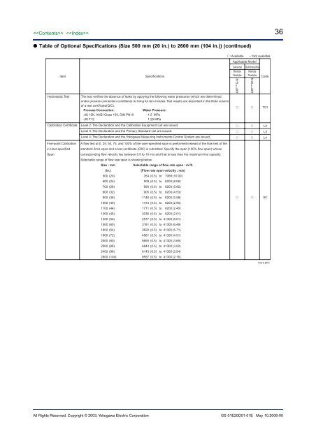
36 Table of Optional Specifications (Size 500 mm (20 in.) to 2600 mm (104 in.)) (continued): Available –: Not availableApplicable ModelItemSpecificationsGeneralRemoteFlowtubeSubmersibleRemoteFlowtube Code<strong>AXF</strong>***G-N<strong>AXF</strong>***W-NHydrostatic TestThe test verifies the absence of leaks by applying the following water pressures (which are determinedunder process connection conditions) to lining for ten minutes. Test results are described in the Note columnof a test certificate(QIC).Process Connection:Water Pressure:JIS 10K, ANSI Class 150, DIN PN10 1.5 MPaJIS F121.25 MPa T01Calibration CertificateLevel 2: The Declaration and the Calibration Equipment List are issued. L2Level 3: The Declaration and the Primary Standard List are issued. L3Level 4: The Declaration and the Yokogawa Measuring Instruments Control System are issued. L4Five-point Calibrationin User-specifiedSpanA flow test at 0, 25, 50, 75, and 100% of the user-specified span is performed instead of the flow test of thestandard 2m/s span and a test certificate (QIC) is submitted. Specify the span (100% flow span) whosecorresponding flow velocity lies between 0.5 to 10 m/s and that is less than the maximum line capacity.Selectable range of flow rate span is showing below.Size : mmSelectable range of flow rate span : m 3 /h(in.)(Flow rate span velocity : m/s)500 (20)354 (0.5) to 7068 (10.00)600 (24)509 (0.5) to 8200 (8.06)700 (28)693 (0.5) to 8200 (5.92)800 (32)905 (0.5) to 8200 (4.53)900 (36)1146 (0.5) to 8200 (3.58)1000 (40)1414 (0.5) to 8200 (2.90)1100 (44)1711 (0.5) to 8200 (2.40)1200 (48)2036 (0.5) to 8200 (2.01)1350 (54)2577 (0.5) to 41300 (8.01)1500 (60)3181 (0.5) to 41300 (6.49)1600 (64)3620 (0.5) to 41300 (5.71)1800 (72)4581 (0.5) to 41300 (4.51)2000 (80)5655 (0.5) to 41300 (3.65)2200 (88)6843 (0.5) to 41300 (3.02)2400 (96)8143 (0.5) to 41300 (2.54)2600 (104)9557 (0.5) to 41300 (2.16) SCT26-6.EPSAll Rights Reserved. Copyright © 2003, Yokogawa Electric <strong>Corp</strong>oration GS 01E20D01-01E May 10,2006-00
37■ EXTERNAL DIMENSIONS <strong>AXF</strong> Standard, <strong>AXF</strong>002-<strong>AXF</strong>015, Wafer Type, PFA Lining<strong>AXF</strong>002G<strong>AXF</strong>005W<strong>AXF</strong>010C<strong>AXF</strong>015*4DEF12 A 1 A 1N NP*4: D, E, F; Integral Flowmeter,N, P; Remote Flowtube49(1.93)Hi73(2.87)Integral Flowmeter154(6.06)HrRemote FlowtubeGround Terminal(M4)ø86(3.38)48 (1.89)70(2.76)H163.5(2.50)3(0.12)DUnit : mm (approx. inch)Integral Flowmeter Remote Flowtube197(7.76)* 1 Ground Terminal(M4)66* 1 51.5 51.5 28(1.1)(2.6) (2.03) (2.03)111(4.37)ø128(5.04)(ød)* No infra-red switches are furnishedfor Fieldbus communication type.L* 24- ø6.2(0.24)7258(2.83)(2.28)ModelRemoteflowtubeIntegral<strong>flowmeter</strong>RemoteflowtubeHeightSize codeSizeLining codeFace-to-facelengthOutside dia.Inner diameter ofGrounding ringMax. HeightWeight kg (lb)* 3L *2DødH1Hr0022.5(0.1)A005 0105(0.2) 10(0.4)A A81(3.19)44(1.73)15(0.59)144(5.67)268(10.55)2.4(5.3)01515(0.5)A*1: When indicator code N is selected, subtract 12 mm (0.47 inch)from the value in the figure.In case of explosion proof type with indicator, add 5 mm (0.2 inch) to it.*2: Depending on the selection of grounding ring code and optionalcode, add the following value to L (face-to-face length).Grounding Ring Code S, L, H, V P, T NNone +0 +26(1.02) -2(0.08)OptionCodeGA, GC, GD(Special Gaskets)+6(0.24) +28(1.10) –*3: When submersible type or option code DHC is selected,waterproof glands and a 30m long cable are attached.Add 9.5kg(20.9lb) to the weight in the table.Integral Max. Height Hi<strong>flowmeter</strong>Weight kg (lb)306(12.03)4.1(9.0)F22.EPS <strong>AXF</strong> Standard, <strong>AXF</strong>025-<strong>AXF</strong>125, Wafer Type, PFA /Polyurethane Rubber /Natural Soft Rubber /EPDMRubber LiningUnit : mm (approx. inch)<strong>AXF</strong>025<strong>AXF</strong>032<strong>AXF</strong>040G<strong>AXF</strong>050W<strong>AXF</strong>065C<strong>AXF</strong>080<strong>AXF</strong>100<strong>AXF</strong>125*5DEFNP12NAUDG12A 1*5: D, E, F; Integral Flowmeter,N, P; Remote Flowtube49(1.93)Hi73(2.87)Integral <strong>flowmeter</strong> Remote Flowtube Integral <strong>flowmeter</strong> Remote FlowtubeGround Terminal(M4)154(6.06) ø86(3.38)48(1.89)Hr70(2.76)Hr66* 1(2.6)197(7.76)* 151.5 51.5(2.03) (2.03)Ground Terminal(M4)28(1.1)111(4.37)ø128(5.04)øD(ød)ModelSize codeSizeLining codeFace-to-facelength L *2Remote Outside dia. øDFlowtubeInner diameter ofGrounding ring ødIntegralFlowmeter Width W* 3Height H1Remote Max. Height HrFlowtubeWeight kg (lb)* 4Integral Max. Height HiFlowmeterWeight kg (lb)* No infra-red switches are furnished L* 2W* 3for Fieldbus communication type.02525(1)03232(1.25)04040(1.5)05050(2)06565(2.5)08080(3)100100(4)125125(5)*1: When indicator code N is selected, subtract 12mm (0.47 inch) from the value in the figure.In case of explosion proof type with indicator, add5 mm (0.2 inch) to it.A,U A,U A,UA,U A,U A,U A,U A,U*2: Depending on the selection of grounding ringD,G D,G D,G D,G D,Gcode and optional code, add the following value to60(2.36) 70(2.76) 70(2.76) 80(3.15) 100(3.94) 120(4.72) 150(5.91) 200(7.87) L (face-to-face length).67.5(2.66) 73(2.87) 86(3.39) 99(3.90) 117(4.61) 129(5.08) 155(6.10) 183(7.20)Grounding Ring Code S, L, H, V P, T NOptionNone+0 +26(1.02) -2(0.08)28(1.10) 34(1.34) 41(1.61) 53(2.09) 66(2.60) 77(3.03) 102(4.02) 128(5.04) Code(Special Gaskets)GA, GC, GD+8(0.31) +30(1.18) –67.5(2.66) 73(2.87) 86(3.39) 99(3.90) 117(4.61) 129(5.08) 155(6.10) 183(7.20) *3: When electrode structure 2 is selected, add thefollowing value to W (width).92(3.62) 98(3.86) 111(4.37) 129(5.08) 147(5.79) 157(6.18) 183(7.20) 212(8.35)216(8.50) 222(8.74) 235(9.25) 253(9.96) 271(10.67) 281(11.06) 307(12.09) 336(13.23)NominalSize25 32, 40, 50 65, 80 100 125W +52.5(2.07) +52(2.05) +49(1.93) +48(1.89) +47(1.85)1.9(4.1) 2.0(4.5) 2.2(4.9) 2.7(5.8) 3.4(7.6) 4.1(9.1) 5.6(12.3) 9.3(20.4) *4: When submersible type or option code DHC isselected, waterproof glands and a 30m long cable254(9.98) 260(10.24) 273(10.73) 291(11.44) 309(12.17) 319(12.54) 345(13.56) 374(14.70) are attached.Add 9.5kg(20.9lb) to the weight in the table.3.6(7.8) 3.7(8.2) 3.9(8.7) 4.4(9.6) 5.1(11.3) 5.8(12.9) 7.3(16.0) 11.0(24.2)F23.EPSAll Rights Reserved. Copyright © 2003, Yokogawa Electric <strong>Corp</strong>oration GS 01E20D01-01E May 10,2006-00
- Page 1 and 2: GeneralSpecificationsGS 01E20D01-01
- Page 3 and 4: Functions “”How to Set Paramete
- Page 5 and 6: 5Size of AXF Flowtubes: AXF Standar
- Page 7 and 8: Flowtube Material:Size 2.5 mm (0.1
- Page 9 and 10: 9Gasket:Joints:UseLiningGeneral-Pur
- Page 11 and 12: CENELEC ATEX (KEMA):*AXF002C - AXF4
- Page 13 and 14: IECEx:*AXF002C - AXF400CApplicable
- Page 15 and 16: Polyurethane Rubber /Natural Soft R
- Page 17 and 18: ■ NORMAL OPERATING CONDITIONSAmbi
- Page 19 and 20: Fluid Temperature and Pressure:Note
- Page 21 and 22: Reasonable Figure for Thermal Shock
- Page 23 and 24: Size500 (20)600 (24)700 (28)800 (32
- Page 25 and 26: 25AXF STANDARD (Wafer /Union Joint
- Page 27 and 28: 27AXF STANDARD (Flange Type) Size 5
- Page 29 and 30: 29REPLACEMENT MODEL FOR EARLIER ADM
- Page 31 and 32: 31■ OPTIONAL SPECIFICATIONS FOR F
- Page 33 and 34: 33 Table of Optional Specifications
- Page 35: 35 Table of Optional Specifications
- Page 39 and 40: 39 AXF Standard, AXF015, Wafer Type
- Page 41 and 42: 41 AXF Standard, AXF002-AXF015, JIS
- Page 43 and 44: 43 AXF Standard, AXF065-AXF125, JIS
- Page 45 and 46: 45 AXF Standard, AXF250-AXF400, JIS
- Page 47 and 48: 47 AXF Standard, AXF015-AXF125, San
- Page 49 and 50: 49 Replacement model for Earlier AD
- Page 51 and 52: 51 Replacement model for Earlier AD
- Page 53 and 54: 53 AXF Standard, AXF11L-AXF13L, JIS
- Page 55 and 56: 55 Unless otherwise specified, diff