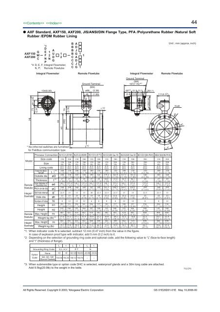
(ød) 44 <strong>AXF</strong> Standard, <strong>AXF</strong>150, <strong>AXF</strong>200, JIS/ANSI/DIN Flange Type, PFA /Polyurethane Rubber /Natural SoftRubber /EPDM Rubber LiningG<strong>AXF</strong>150W<strong>AXF</strong>200C*4DEFNP12NAUDG12*4: D, E, F; Integral Flowmeter,N, P; Remote FlowtubeBBBBCCCCADJGADJG111Unit : mm (approx. inch)Integral Flowmeter Remote Flowtube Integral Flowmeter Remote Flowtube154(6.06)Ground Terminal(M4)ø86 (3.38)48 (1.89)Ground Terminal(M4)197(7.76)* 166* 1 51.5 51.5(2.6) (2.03) (2.03)28(1.1)111(4.37)73 49 (1.93)(2.87)70(2.76)t * 2ø128(5.04)N-øhøDHiH1Hr(H2)øC* No infra-red switches are furnishedfor Fieldbus communication type.L* 2θ°ModelRemoteflowtubeIntegral<strong>flowmeter</strong>RemoteflowtubeIntegral<strong>flowmeter</strong>Process Connection BJ1/CJ1(JIS10K) BJ2/CJ2(JIS20K) BG1/CG1(JIS F12) BA1/CA1(ANSI Class 150) BA2/CA2(ANSI Class 300) BD1/CD1(DIN PN10) BD2/CD2(DIN PN16)Size codeSizeLining codeFace-to-facelengthOutside dia.ThicknessInner diameter ofGrounding ringPitch circle dia.Bolt hole intervalHole dia.Number of holesHeightHeightMax. HeightHrWeight kg (lb)Max. Height0L -3*2øCøhNH1H2HiWeight kg (lb)øDt* 2ød˚* 3150150(6)A,UD,G300(11.81)280(11.02)27(1.06)146.1(5.75)240(9.45)22.523(0.91)8281(11.06)141(5.55)405(15.94)27.8(61.3)443(17.42)29.5(65.0)200200(8)A,UD,G350(13.78)330(12.99)27(1.06)193.6(7.62)290(11.42)1523(0.91)12331(13.03)166(6.54)455(17.91)37.3(82.2)493(19.39)39.0(86.0)150150(6)A,UD,G300(11.81)305(12.01)33(1.30)146.1(5.75)260(10.24)1525(0.98)12294(11.56)141(5.55)418(16.44)37.1(81.8)456(17.95)38.8(85.5)200200(8)A,UD,G350(13.78)350(13.78)35(1.38)193.6(7.62)305(12.01)1525(0.98)12341(13.43)166(6.54)465(18.31)51.9(114.4)503(19.80)53.6(118.2)150150(6)A,UD,G300(11.81)290(11.42)27(1.06)146.1(5.75)247(9.72)3019(0.75)6286(11.26)141(5.55)410(16.14)29.9(65.9)448(17.64)31.6(69.7)*1: When indicator code N is selected, subtract 12 mm (0.47 inch) from the value in the figure.In case of explosion proof type with indicator, add 5 mm (0.2 inch) to it.*2: Depending on the selection of grounding ring code and optional code, add the following value to “L” (face-to-face length)and “t” (thickness of flange).L t L t L tGrounding Ring Code S, L, H, V P, T NNone +0 +0 +32(1.26) +16(0.63) -2(0.08) -1(0.04)OptionCode GA, GC, GD +10(0.39) +5(0.20) +38(1.5) +19(0.75) – –(Special Gaskets)*3: When submersible type or option code DHC is selected, waterproof glands and a 30m long cable are attached.Add 9.5kg(20.9lb) to the weight in the table.200200(8)A,UD,G350(13.78)342(13.46)29(1.14)193.6(7.62)299(11.77)22.519(0.75)8337(13.27)166(6.54)461(18.15)43.2(95.3)499(19.65)44.9(99.0)150150(6)A,UD,G300(11.81)279.4(11.00)30.4(1.20)146.1(5.75)241.3(9.50)22.522.4(0.88)8281(11.05)141(5.55)405(15.93)30.9(68.0)443(17.43)32.6(71.8)200200(8)A,UD,G350(13.78)342.9(13.50)33.4(1.31)193.6(7.62)298.5(11.75)22.522.4(0.88)8337(13.29)166(6.54)461(18.17)49.2(108.4)499(19.66)50.9(112.2)150150(6)A,UD,G300(11.81)317.5(12.50)43.5(1.71)146.1(5.75)269.7(10.62)1522.4(0.88)12300(11.80)141(5.55)424(16.68)52.5(115.7)462(18.18)54.2(119.5)200200(8)A,UD,G350(13.78)381.0(15.00)46.1(1.81)193.6(7.62)330.2(13.00)1525.4(1.00)12357(14.04)166(6.54)481(18.92)78.8(173.7)519(20.41)80.5(177.5)200200(8)A,UD,G350(13.78)340(13.39)29(1.14)193.6(7.62)295(11.61)22.522(0.87)8336(13.23)166(6.54)460(18.11)42.5(93.7)498(19.61)44.2(97.5)150150(6)A,UD,G300(11.81)285(11.22)27(1.06)146.1(5.75)240(9.45)22.522(0.87)8284(11.16)141(5.55)408(16.04)28.7(63.2)446(17.54)30.4(66.9)200200(8)A,UD,G350(13.78)340(13.39)29(1.14)193.6(7.62)295(11.61)1522(0.87)12336(13.23)166(6.54)460(18.11)41.9(92.5)498(19.61)43.6(96.2)F32.EPSAll Rights Reserved. Copyright © 2003, Yokogawa Electric <strong>Corp</strong>orationGS 01E20D01-01E May 10,2006-00
45 <strong>AXF</strong> Standard, <strong>AXF</strong>250-<strong>AXF</strong>400, JIS/ANSI/DIN Flange Type, PFA /Polyurethane Rubber /Natural SoftRubber /EPDM Rubber Lining<strong>AXF</strong>250G<strong>AXF</strong>300W<strong>AXF</strong>350C<strong>AXF</strong>400Hi*4DEFNP12NAUDG12*4: D, E, F; Integral Flowmeter,N, P; Remote Flowtube(1.93)4973(2.87)H1(2.76)70(H2)BBBBCCCCADJGADJG111H3Hrø128(5.04)Unit : mm (approx. inch)Integral Flowmeter Remote Flowtube Integral Flowmeter Remote FlowtubeGround Termonal(M4)Ground Terminal197(7.76)* 1154(6.06)ø86 (3.38) (M4)48(1.89)66* 1 51.5 51.5 28(1.1)(2.03) (2.03)Eye Bolt(2.6)111 (4.37)L* 2 N- øht* 2θ°(ød)øDøCModel* No infra-red switches are furnishedfor Fieldbus communication type.Process ConnectionSize codeSizeLining code250BJ1/CJ1(JIS10K)300350400BJ2/CJ2(JIS20K)250 300BG1/CG1(JIS F12)BA1/CA1(ANSI Class 150)BA2/CA2(ANSI Class 300)*3: When submersible type or option code DHC is selected, waterproof glands and a 30m long cable are attached.Add 9.5kg(20.9lb) to the weight in the table.250300350for <strong>AXF</strong>300, <strong>AXF</strong>350, <strong>AXF</strong>400BD1/CD1(DIN PN10)BD2/CD2(DIN PN16)250 300 350 400 250 300 250 300 350 400 250 300 350 400 250 300 250 300 350 400 250 300(10) (12) (14) (16) (10) (12) (10) (12) (14) (16) (10) (12) (14) (16) (10) (12) (10) (12) (14) (16) (10) (12)A,UD,GA,UD,GA,UD,GA,UD,GA,UD,GA,UD,GA,UD,GA,UD,GA,UD,GA,UD,GA,UD,GA,UD,GA,UD,GA,UD,GA,UD,GA,UD,GA,UD,GA,UD,GA,UD,GA,UD,GA,UD,GA,UD,GFace-to-face 0length L -5450 500 550 600 450 500 450 500 550 600 450 500 550 600 450 500 450 500 550 600 450 500(17.72)(19.69)(21.65)(23.62)(17.72)(19.69) (17.72) (19.69)(21.65)(23.62)(17.72)(19.69) (21.65) (23.62) (17.72) (19.69) (17.72) (19.69) (21.65) (23.62) (17.72) (19.69)Outside dia. øD400 445 490 560 430 480 410 464 530 582 406.4 482.6 533.4 596.9 444.5 520.7 395 445 505 565 405 460(15.75)(17.52)(19.29)(22.05)(16.93)(18.90) (16.14) (18.27)(20.87)(22.91)(16.00)(19.00) (21.00) (23.50) (17.50) (20.50) (15.55) (17.52) (19.88) (22.24) (15.94) (18.11)Thickness t* 2 32 34 36 38 42 44 32 34 36 36 38.2 39.8 45.1 46.6 55.7 58.8 34 34 36 36 34 36(1.26) (1.34) (1.42) (1.50) (1.65) (1.73) (1.26) (1.34) (1.42) (1.42) (1.50) (1.57) (1.78) (1.83) (2.19) (2.31) (1.34) (1.34) (1.42) (1.42) (1.34) (1.42)Inner diameter of243 291.3 323.4 373.5 243 291.3 243 291.3 323.4 373.5 243 291.3 323.4 373.5 243 291.3 243 291.3 323.4 373.5 243 291.3Remote Grounding ring ød (9.57) (11.47)(12.73)(14.70) (9.57) (11.47) (9.57) (11.47)(12.73)(14.70) (9.57) (11.47) (12.73) (14.70) (9.56) (11.47) (9.57) (11.47) (12.73) (14.70) (9.57) (11.47)flowtube355 400 445 510 380 430 360 414 472 524 362.0 431.8 476.3 539.8 387.4 450.9 350 400 460 515 355 410Pitch circle dia. øC (13.98)(15.75)(17.52)(20.08)(14.96)(16.93) (14.17) (16.30)(18.58)(20.63)(14.25)(17.00) (18.75) (21.25) (15.25) (17.75) (13.78) (15.75) (18.11) (20.28) (13.98) (16.14)Integral Bolt hole interval ˚ 15 11.25 11.25 11.25 15 11.25 22.5 18 18 15 15 15 15 11.25 11.25 11.25 15 15 11.25 11.25 15 15<strong>flowmeter</strong>25 25 25 27 27 27 23 23 25 25 25.4 25.4 28.4 28.4 28.4 31.8 22 22 22 26 26 26Hole dia. øh (0.98) (0.98) (0.98) (1.06) (1.06) (1.06) (0.91) (0.91) (0.98) (0.98) (1.00) (1.00) (1.12) (1.12) (1.12) (1.25) (0.87) (0.87) (0.87) (1.02) (1.02) (1.02)Number of holes N 12 16 16 16 12 16 8 10 10 12 12 12 12 16 16 16 12 12 16 16 12 12HeightHeightH1H2400 447 491 553 415 464 405 456 511 564 403 466 512 572 422 485 397 447 498 556 402 454(15.75)(17.60)(19.33)(21.77)(16.34)(18.27)(15.94)(17.95)(20.12)(22.20)(15.87)(18.35) (20.16) (22.52) (16.61) (19.09) (15.63) (17.60) (19.61) (21.89) (15.83) (17.87)197 221 243 270 197 221 197 221 243 270 197 221 243 270 197 221 197 221 243 270 197 221(7.76) (8.70) (9.57) (10.63) (7.76) (8.70) (7.76) (8.70) (9.57) (10.63) (7.76) (8.70) (9.57) (10.63) (7.76) (8.70) (7.76) (8.70) (9.57) (10.63) (7.76) (8.70)Height H3454 499 553 623 484 534 464 518 593 645 460 537 596 660 499 575 449 499 568 628 459 514(17.87)(19.65)(21.77)(24.53)(19.06)(21.02)(18.27)(20.39)(23.35)(25.39)(18.11)(21.14) (23.46) (25.98) (19.65) (22.64) (17.68) (19.65) (22.36) (24.72) (18.07) (20.24)Remote Max. Height Hr524 571 615 677 539 588 529 580 635 688 527 590 636 696 546 609 521 571 622 680 526 578(20.63)(22.48)(24.21)(26.65)(21.22)(23.15)(20.83)(22.83)(25.00)(27.09)(20.75)(23.23) (25.04) (27.40) (21.50) (23.98) (20.51) (22.48) (24.49) (26.77) (20.71) (22.76)flowtubeWeight kg (lb)* 3 70.0 78.0 107.0 135.0 98.5 114.5 73.4 85.0 121.2 137.0 83.4 104.8 151.8 185.3 133.0 176.7 73.0 79.4 112.5 129.7 74.8 87.9(154.3)(172.0)(235.9)(297.6)(217.2)(252.4)(161.7)(187.4)(267.2)(301.9)(183.8)(231.0) (334.7) (408.5) (293.1) (389.5) (161.0) (174.9) (248.0) (285.9) (164.9) (193.8)Integral Max. Height Hi562 609 653 715 577 626 567 618 673 726 565 628 674 734 584 647 559 609 660 718 564 616(22.13)(23.98)(25.71)(28.15)(22.72)(24.65)(22.32)(24.33)(26.50)(28.58)(22.24)(24.72) (26.54) (28.90) (22.99) (25.47) (22.01) (23.98) (25.98) (28.27) (22.20) (24.25)<strong>flowmeter</strong>71.7 79.7 108.7 136.7 100.2 116.2 75.1 86.7 122.9 138.7 85.1 106.5 153.5 187.0 134.7 178.4 74.7 81.1 114.2 131.4 76.5 89.6Weight kg (lb) (158.1)(175.7)(239.6)(301.4)(220.9)(256.2)(165.5)(191.2)(270.9)(305.7)(187.6)(234.8) (338.4) (412.3) (296.9) (393.3) (164.7) (178.7) (251.7) (289.6) (168.7) (197.6)*1: When indicator code N is selected, subtract 12 mm (0.47 inch) from the value in the figure.In case of explosion proof type with indicator, add 5 mm (0.2 inch) to it.*2: Depending on the selection of grounding ring code and optional code, add the following value to “L” (face-to-face length)and “t” (thickness of flange).Nominal Size: 250 mm to 300 mmNominal Size: 350 mm to 400 mmL t L tL t L tGrounding Ring Code S, L, H, V NGrounding Ring Code S, L, H, V NOption Code is “None” +0 +0 -6(0.24) -3(0.12) Option Code is “None” +0 +0 -10(0.39) -5(0.20)400250300350400250300250300350400250300F33.EPSAll Rights Reserved. Copyright © 2003, Yokogawa Electric <strong>Corp</strong>oration GS 01E20D01-01E May 10,2006-00
- Page 1 and 2: GeneralSpecificationsGS 01E20D01-01
- Page 3 and 4: Functions “”How to Set Paramete
- Page 5 and 6: 5Size of AXF Flowtubes: AXF Standar
- Page 7 and 8: Flowtube Material:Size 2.5 mm (0.1
- Page 9 and 10: 9Gasket:Joints:UseLiningGeneral-Pur
- Page 11 and 12: CENELEC ATEX (KEMA):*AXF002C - AXF4
- Page 13 and 14: IECEx:*AXF002C - AXF400CApplicable
- Page 15 and 16: Polyurethane Rubber /Natural Soft R
- Page 17 and 18: ■ NORMAL OPERATING CONDITIONSAmbi
- Page 19 and 20: Fluid Temperature and Pressure:Note
- Page 21 and 22: Reasonable Figure for Thermal Shock
- Page 23 and 24: Size500 (20)600 (24)700 (28)800 (32
- Page 25 and 26: 25AXF STANDARD (Wafer /Union Joint
- Page 27 and 28: 27AXF STANDARD (Flange Type) Size 5
- Page 29 and 30: 29REPLACEMENT MODEL FOR EARLIER ADM
- Page 31 and 32: 31■ OPTIONAL SPECIFICATIONS FOR F
- Page 33 and 34: 33 Table of Optional Specifications
- Page 35 and 36: 35 Table of Optional Specifications
- Page 37 and 38: 37■ EXTERNAL DIMENSIONS AXF Stand
- Page 39 and 40: 39 AXF Standard, AXF015, Wafer Type
- Page 41 and 42: 41 AXF Standard, AXF002-AXF015, JIS
- Page 43: 43 AXF Standard, AXF065-AXF125, JIS
- Page 47 and 48: 47 AXF Standard, AXF015-AXF125, San
- Page 49 and 50: 49 Replacement model for Earlier AD
- Page 51 and 52: 51 Replacement model for Earlier AD
- Page 53 and 54: 53 AXF Standard, AXF11L-AXF13L, JIS
- Page 55 and 56: 55 Unless otherwise specified, diff