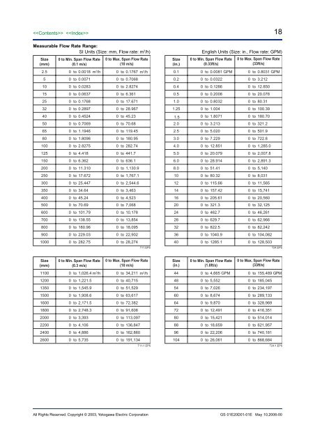
Measurable Flow Rate Range:SI Units (Size: mm, Flow rate: m 3 /h)Size(mm)0 to Min. Span Flow Rate(0.1 m/s)0 to Max. Span Flow Rate(10 m/s)2.5 0 to 0.0018 m 3 /h 0 to 0.1767 m 3 /h5 0 to 0.00710 to 0.706810 0 to 0.02830 to 2.827415 0 to 0.06370 to 6.36125 0 to 0.17680 to 17.67132 0 to 0.28970 to 28.96740 0 to 0.45240 to 45.2350 0 to 0.70690 to 70.6865 0 to 1.19460 to 119.4580 0 to 1.80960 to 180.95100 0 to 2.82750 to 282.74125 0 to 4.4180 to 441.7150 0 to 6.3620 to 636.1200 0 to 11.3100 to 1,130.9250 0 to 17.6720 to 1,767.1300 0 to 25.4470 to 2,544.6350 0 to 34.640 to 3,463400 0 to 45.240 to 4,523500 0 to 70.690 to 7,068600 0 to 101.790 to 10,178700 0 to 138.550 to 13,854800 0 to 180.960 to 18,095900 0 to 229.030 to 22,9021000 0 to 282.750 to 28,274T11.EPSSize(in.)18English Units (Size: in., Flow rate: GPM)0 to Min. Span Flow Rate(0.33ft/s)0 to Max. Span Flow Rate(33ft/s)0.1 0 to 0.0081 GPM 0 to 0.8031 GPM0.2 0 to 0.03220 to 3.2120.4 0 to 0.12860 to 12.8500.5 0 to 0.20080 to 20.0781.0 0 to 0.80320 to 80.311.25 0 to 1.0040 to 100.391.5 0 to 1.80710 to 180.702.0 0 to 3.2130 to 321.22.5 0 to 5.0200 to 501.93.0 0 to 7.2290 to 722.84.0 0 to 12.8510 to 1,285.05.0 0 to 20.0790 to 2,007.86.0 0 to 28.9140 to 2,891.38.0 0 to 51.410 to 5,14010 0 to 80.320 to 8,03112 0 to 115.660 to 11,56514 0 to 157.420 to 15,74116 0 to 205.610 to 20,56020 0 to 321.30 to 32,12524 0 to 462.70 to 46,26128 0 to 629.70 to 62,96632 0 to 822.50 to 82,24236 0 to 1040.90 to 104,08240 0 to 1285.10 to 128,503T24.EPSSize(mm)0 to Min. Span Flow Rate(0.3 m/s)0 to Max. Span Flow Rate(10 m/s)1100 0 to 1,026.4 m 3 /h 0 to 34,211 m 3 /h1200 0 to 1,221.50 to 40,7151350 0 to 1,545.90 to 51,5291500 0 to 1,908.60 to 63,6171600 0 to 2,171.50 to 72,3821800 0 to 2,748.30 to 91,6082000 0 to 3,3930 to 113,0972200 0 to 4,1060 to 136,8472400 0 to 4,8860 to 162,8602600 0 to 5,7350 to 191,134T11-1.EPSSize(in.)0 to Min. Span Flow Rate(1.0ft/s)0 to Max. Span Flow Rate(33ft/s)44 0 to 4,665 GPM 0 to 155,489 GPM48 0 to 5,5520 to 185,04554 0 to 7,0260 to 234,19760 0 to 8,6740 to 289,13364 0 to 9,8700 to 328,96972 0 to 12,4910 to 416,35180 0 to 15,4210 to 514,01488 0 to 18,6590 to 621,95796 0 to 22,2060 to 740,181104 0 to 26,0610 to 868,684T24-1.EPSAll Rights Reserved. Copyright © 2003, Yokogawa Electric <strong>Corp</strong>oration GS 01E20D01-01E May 10,2006-00
Fluid Temperature and Pressure:Note *1 The following figures show maximum allowablefluid pressure for the flowtube itself. Further fluidpressure should also be limitted according toflange rating.*2 For fluid temperature of the explosion prooftype, refer to descriptions of “HAZARDOUSAREA CLASSIFICATION”.PFA Lining (*1)General-Purpose Use, Submersible Type, Explosionproof Type, Remote Flowtube (electrode structurecode 1: Non-replaceable electrode)PressureMPa (psi)4 (580)2 (290)1 (145)– 0.1 (–14.5)– 40(–40)2.5 to 50 mm (0.1 to 2.0 in.) (flange type, wafer type)65 to 200 mm (2.5 to 8.0 in.) (flange type, wafer type)250, 300 mm (10, 12 in.) (flange type)250, 300 mm (10, 12 in.) (wafer type)350, 400 mm (14, 16 in.) (flange type)*1–10 0 +40+100 +130 +150 +160(+14) (+32) (+104)(+212) (+266) (+302) (+320)Temperature °C (°F)F18-1.EPSGeneral-Purpose Use and Explosion proof Type,Integral Flowmeter (electrode structure code 1:Non-replaceable electrode)PressureMPa (psi)4 (580)2 (290)1 (145)2.5 to 50 mm (0.1 to 2.0 in.) (flange type, wafer type)65 to 200 mm (2.5 to 8.0 in.) (flange type, wafer type)250, 300 mm (10, 12 in.) (flange type)250, 300 mm (10, 12 in.) (wafer type)350, 400 mm (14, 16 in.) (flange type)*1– 0.1 (–14.5)– 40 –10 0 40 100 130(– 40) (14) (32) (104) (212) (266)Temperature °C (°F)F18-2.EPS*1: For lay length code 2 in wafer types of 25 mm (1.0 in.),and for wafer types of 32 mm to 300 mm(1.25 to 12in.), and for carbon steel flange types (process connectioncode: C **) of 50 to 400 mm (2.0 to 16 in.) theminimum temperature is –10°C (+14°F).*2: For fluid temperature of the explosion proof type,refer to descriptions of “HAZARDOUS AREACLASSIFICATION”.19General-Purpose Use, Remote Flowtube (electrodestructure code 2: replaceable electrode)PressureMPa (psi)2 (290)1 (145)– 0.1 (–14.5)25 to 200 mm (1.0 to 8.0 in.) (flange type, wafer type)250, 300 mm (10, 12 in.) (flange type)350, 400 mm (14 to 16 in.) (flange type)250, 300 mm (10, 12 in.) (wafer type)–10 0 40 100(14) (32) (104) (212)Temperature °C (°F)130(266)160(320)F18-3.EPSGeneral-Purpose Use, Integral Flowmeter (electrodestructure code 2: replaceable electrode)PressureMPa (psi)2 (290)1 (145)– 0.1 (–14.5)–10 0(14) (32)25 to 200 mm (1.0 to 8.0 in.) (flange type, wafer type)250, 300 mm (10, 12 in.) (flange type)350, 400 mm (14 to 16 in.) (flange type)250, 300 mm (10, 12 in.) (wafer type)40(104)100(212)130(266)Temperature °C (°F)F18-4.EPSNote: For replaceable electrodes for fluid temperatures of10°C (50°F)or less, please contact Yokogawa office.Sanitary Type (electrode structure code 1: Nonreplaceableelectrode)PressureMPa (psi)1(145)–0.1(–14.5)15 to 125 mm (0.5 to 5.0 in.) (remote flowtube)15 to 125 mm (0.5 to 5.0 in.) (integral <strong>flowmeter</strong>)–10 0(+14) (+32)+130(+266)+160(+320)Temperature °C (°F)Note: In case of 120 to 160°C (248 to 320°F) of fluidtemperature, please select optional code GH.F18-5.EPSCeramics LiningGeneral-Purpose Use and Explosion proof Type,Remote Flowtube (electrode structure code 1: Nonreplaceableelectrode)PressureMPa (psi)4 (580)2.5 to 50 mm (0.1 to 2.0 in.)80 to 200 mm (3.0 to 8.0 in.)2 (290)–0.1 (–14.5)–10 0(+14) (+32)+80 +120(+175) (+248)Temperature °C (°F)+180(+356)F19-1.EPSAll Rights Reserved. Copyright © 2003, Yokogawa Electric <strong>Corp</strong>oration GS 01E20D01-01E May 10,2006-00
- Page 1 and 2: GeneralSpecificationsGS 01E20D01-01
- Page 3 and 4: Functions “”How to Set Paramete
- Page 5 and 6: 5Size of AXF Flowtubes: AXF Standar
- Page 7 and 8: Flowtube Material:Size 2.5 mm (0.1
- Page 9 and 10: 9Gasket:Joints:UseLiningGeneral-Pur
- Page 11 and 12: CENELEC ATEX (KEMA):*AXF002C - AXF4
- Page 13 and 14: IECEx:*AXF002C - AXF400CApplicable
- Page 15 and 16: Polyurethane Rubber /Natural Soft R
- Page 17: ■ NORMAL OPERATING CONDITIONSAmbi
- Page 21 and 22: Reasonable Figure for Thermal Shock
- Page 23 and 24: Size500 (20)600 (24)700 (28)800 (32
- Page 25 and 26: 25AXF STANDARD (Wafer /Union Joint
- Page 27 and 28: 27AXF STANDARD (Flange Type) Size 5
- Page 29 and 30: 29REPLACEMENT MODEL FOR EARLIER ADM
- Page 31 and 32: 31■ OPTIONAL SPECIFICATIONS FOR F
- Page 33 and 34: 33 Table of Optional Specifications
- Page 35 and 36: 35 Table of Optional Specifications
- Page 37 and 38: 37■ EXTERNAL DIMENSIONS AXF Stand
- Page 39 and 40: 39 AXF Standard, AXF015, Wafer Type
- Page 41 and 42: 41 AXF Standard, AXF002-AXF015, JIS
- Page 43 and 44: 43 AXF Standard, AXF065-AXF125, JIS
- Page 45 and 46: 45 AXF Standard, AXF250-AXF400, JIS
- Page 47 and 48: 47 AXF Standard, AXF015-AXF125, San
- Page 49 and 50: 49 Replacement model for Earlier AD
- Page 51 and 52: 51 Replacement model for Earlier AD
- Page 53 and 54: 53 AXF Standard, AXF11L-AXF13L, JIS
- Page 55 and 56: 55 Unless otherwise specified, diff