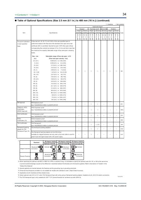
34 Table of Optional Specifications (Size 2.5 mm (0.1 in.) to 400 mm (16 in.)) (continued)ItemFive-point Calibrationin User-specifiedSpanSpecificationsA flow test at 0, 25, 50, 75, and 100% of the user-specified span isperformed instead of the flow test of the standard 2m/s span and a testcertificate (QIC) is submitted. Specify the span (100% flow span) whosecorresponding flow velocity lies between 0.5 to 10 m/s and that is less thanthe maximum line capacity. Selectable range of flow rate span is showingbelow.IntegralFlowmeter<strong>AXF</strong>***G-D<strong>AXF</strong>***G-EGeneralRemoteFlowtube<strong>AXF</strong>***G-N<strong>AXF</strong>***G-P: Available –: Not availableApplicable ModelExplosion proof Submersible SanitaryIntegralFlowmeter<strong>AXF</strong>***C-D<strong>AXF</strong>***C-ERemoteFlowtube<strong>AXF</strong>***C-N<strong>AXF</strong>***C-PRemoteFlowtube<strong>AXF</strong>***W-N<strong>AXF</strong>***W-PIntegralFlowmeter<strong>AXF</strong>***H-D<strong>AXF</strong>***H-ERemoteFlowtube<strong>AXF</strong>***H-N<strong>AXF</strong>***H-PCodeSize : mm(in.)2.5 (0.1)5 (0.2)10 (0.4)15 (0.5)25 (1)32 (1.25)40 (1.5)50 (2)65 (2.5)80 (3)100 (4)125 (5)150 (6)200 (8)250 (10)300 (12)350 (14)400 (16)Selectable range of flow rate span : m 3 /h(Flow rate span velocity : m/s)0.009 (0.5) to 0.05 (2.83)0.036 (0.5) to 0.2 (2.83)0.15 (0.5) to 0.96 (3.40)0.32 (0.5) to 2.8 (4.40)0.89 (0.5) to 11 (6.22)1.45 (0.5) to 8.9 (10.00)2.27 (0.5) to 32 (7.07)3.54 (0.5) to 56 (7.92)5.98 (0.5) to 80 (6.70)9.05 (0.5) to 126 (6.96)14.2 (0.5) to 220 (7.78)22.1 (0.5) to 300 (6.79)31.9 (0.5) to 380 (5.97)56.6 (0.5) to 670 (5.92)88.4 (0.5) to 1000 (5.66)128 (0.5) to 1200 (4.72)174 (0.5) to 1200 (3.47)227 (0.5) to 1350 (2.98) SCFM ApprovalCENELEC ATEXCertification(KEMA Approval)CSA CertificationIECExCertification (*5)TIIS CertificationFlameproof packingadapter for TIISFlameproof Type (*6)FM Explosion proofSee “HAZARDOUS AREA CLASSIFICATION”ATEX Explosion proofSee “HAZARDOUS AREA CLASSIFICATION”CSA Explosion proofSee “HAZARDOUS AREA CLASSIFICATION”IECEx Explosion proofSee “HAZARDOUS AREA CLASSIFICATION”TIIS FlameproofSee “HAZARDOUS AREA CLASSIFICATION”Two flameproof packing adaptersOne flameproof packing adapter and one blind plug.Available for integral <strong>flowmeter</strong> and only when a four-wire cable is used forpower input and signal output with a DC power supply.– – – – – FF1– – – – – KF2– – – – – CF1– – – – – – SF2– – (*7) – – – JF3– – – – – G12– – – – – – G11*1:Standard90-degree rotation 180-degree rotation 90-degree rotationOptional Code RA Optional Code RB Optional Code RCIntegral FlowmeterElectricalConnectionIndicatorElectricalConnectionIndicatorRemote FlowtubeElectricalConnectionElectricalConnection*2: When specifying the optional code BCC or BSC for a PFA or ceramics lining, it is advisable to specify the optional code GA, GC, or GD at the same timeto prevent potential leakage caused by the difference in elasticity between the flowtube and chloroprene gaskets. Refer to description of “Gasket” in the“Wetted Part Material”.*3: Special gaskets are inserted between the flowtube and the grounding ring or grounding electrode.*4: Enhanced dual frequency excitation is not available for models with calibration code C (High Grade Accuracy).*5: Applicable only for Australia and New Zealand area.*6: Select optional code G12 or G11 when TIIS Flameproof type with wiring using a flameproof packing adapter. Available only for JIS G1/2 electric connection.*7: The TIIS flameproof type is only available for <strong>AXF</strong>***C-P (remote flowtube for combined use with <strong>AXF</strong>A14).T26-4.EPSAll Rights Reserved. Copyright © 2003, Yokogawa Electric <strong>Corp</strong>oration GS 01E20D01-01E May 10,2006-00
35 Table of Optional Specifications (Size 500 mm (20 in.) to 2600 mm (104 in.)): Available –: Not availableApplicable ModelItemFor District Heatingand Cooling orCondensation-proofSpecificationsUrethane resin potting is applied in the terminal box of a remote flowtube. Select JIS G1/2 for the electricalconnections. 30-m dedicated and excitation cables are pre-wired and waterproof glands with union joints are attachedat factory.GeneralRemoteFlowtube<strong>AXF</strong>***G-NSubmersibleRemoteFlowtube Code<strong>AXF</strong>***W-N – DHCUser-specified Signaland Excitation CableLengthMass Unit SettingG3/4 FemaleWaterproof GlandsWaterproof GlandsWaterproof Glandswith Union JointsStainless Steel TagPlateAvailable for the submersible type and a model with optional code DHC. The cable length is limited up to 200 meterswhen combined with an <strong>AXF</strong>A11 converter. Following “L,” specify the cable length in three digits as a multiple of 1meter (e. g., 001, 002, or 005) for a length up to 5 meters, or as a multiple of 5 meters (i.e., 005, 010, 015, or the like)for a length of 5 meters or more. If this optional code is not selected, a 30m long cable is attached.The flow rate span, transmission pulse weight, and totalizer display pulse weight can be set in terms of mass unit.Specify the density of the process fluid when ordering in addition to the mass flow rate span, transmission pulseweight (for mass unit), and totalizer display pulse weight (for mass unit).When ordering a remote flowtube, parameters for 'Mass Unit Setting' will be set in the corresponding converter beforeshipment.1. Densitya. Available density Numerics:Specify the numeric within the value of 0.0001 to 32000. And it can be up to five digits, to a maximum of32000 ignoring the decimal point. A fraction is limited to the fourth decimal place.b. Available density units: kg/m 3 , lb/gal, lb/cfExample: A water density is about 1000kg/m 3 . In this case specify “1000kg/m 3 ”.However a density is changed by temperature. Specify the actual density.(The 1000kg/m 3 is equivalent to 8.345lb/gal and 62.43lb/cf.)2. The mass flow rate span, transmission pulse weight, and totalizer display pulse weighta. Available density Numerics:Specify the numeric within the value of 0.0001 to 32000. And it can be up to five digits, to a maximum of32000 ignoring the decimal point. A fraction is limited to the fourth decimal place.b. Mass Units Available mass units: t, kg, g, klb, lbAvailable time units: /d, /h, /min, /sNote1: In case of specifying the mass flow span, calculate the volumetric flow span by the setting density, and specifythe available value in the mass flow span.Note2: In case of transmission pulse weight and totalizer display pulse weight, specify the mass unit which wasspecified as the flow unit.Waterproof glands for G3/4 conduits or flexible tubes are attached to the electrical connections. Available only for JISG1/2 electric connections.Waterproof glands are attached to the electrical connections. Available only for JIS G1/2 electric connections.Waterproof glands with union joints are attached to the electrical connections. Available only for JIS G1/2 electricconnections.Screwd JIS SUS304 (AISI 304 SS/EN 1.4301 stainless steel equivalent) stainless steel tag plate for size 1100 to 2600mm, or a pendant tag plate of JIS SUS304 is provided for size 500 to 1000 mm. Choose this option when a SS tagplate is required in addition to the standard nameplate with the tag number inscribed on it.Dimension (Height Width): Appr. 12.5 (4.92) 40 (15.7) mm (inch) L*** MU – EW – EG – EU SCTDirection Change of +90 degrees rotated terminal box to change the direction of the electrical connection. Available for 1000 mmElectrical Connection (*1) (40 in.) and smaller sizes.+180 degrees rotated terminal box to change the direction of the electrical connection. Available for 1000 mm (40 in.)and smaller sizes.–90 degrees rotated terminal box to change the direction of the electrical connection. Available for 1000 mm (40 in.)and smaller sizes. RA RB RCMaterial CertificateMaterial certificates are provided for linings, electrodes, grounding rings, and flanges. M01*1:Standard90-degree rotation 180-degree rotation 90-degree rotationOptional Code RA Optional Code RB Optional Code RCRemote FlowtubeElectricalConnectionElectricalConnectionT26-5.EPSAll Rights Reserved. Copyright © 2003, Yokogawa Electric <strong>Corp</strong>oration GS 01E20D01-01E May 10,2006-00
- Page 1 and 2: GeneralSpecificationsGS 01E20D01-01
- Page 3 and 4: Functions “”How to Set Paramete
- Page 5 and 6: 5Size of AXF Flowtubes: AXF Standar
- Page 7 and 8: Flowtube Material:Size 2.5 mm (0.1
- Page 9 and 10: 9Gasket:Joints:UseLiningGeneral-Pur
- Page 11 and 12: CENELEC ATEX (KEMA):*AXF002C - AXF4
- Page 13 and 14: IECEx:*AXF002C - AXF400CApplicable
- Page 15 and 16: Polyurethane Rubber /Natural Soft R
- Page 17 and 18: ■ NORMAL OPERATING CONDITIONSAmbi
- Page 19 and 20: Fluid Temperature and Pressure:Note
- Page 21 and 22: Reasonable Figure for Thermal Shock
- Page 23 and 24: Size500 (20)600 (24)700 (28)800 (32
- Page 25 and 26: 25AXF STANDARD (Wafer /Union Joint
- Page 27 and 28: 27AXF STANDARD (Flange Type) Size 5
- Page 29 and 30: 29REPLACEMENT MODEL FOR EARLIER ADM
- Page 31 and 32: 31■ OPTIONAL SPECIFICATIONS FOR F
- Page 33: 33 Table of Optional Specifications
- Page 37 and 38: 37■ EXTERNAL DIMENSIONS AXF Stand
- Page 39 and 40: 39 AXF Standard, AXF015, Wafer Type
- Page 41 and 42: 41 AXF Standard, AXF002-AXF015, JIS
- Page 43 and 44: 43 AXF Standard, AXF065-AXF125, JIS
- Page 45 and 46: 45 AXF Standard, AXF250-AXF400, JIS
- Page 47 and 48: 47 AXF Standard, AXF015-AXF125, San
- Page 49 and 50: 49 Replacement model for Earlier AD
- Page 51 and 52: 51 Replacement model for Earlier AD
- Page 53 and 54: 53 AXF Standard, AXF11L-AXF13L, JIS
- Page 55 and 56: 55 Unless otherwise specified, diff