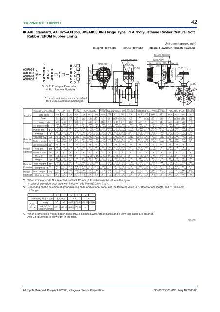
42 <strong>AXF</strong> Standard, <strong>AXF</strong>025-<strong>AXF</strong>050, JIS/ANSI/DIN Flange Type, PFA /Polyurethane Rubber /Natural SoftRubber /EPDM Rubber LiningIntegral FlowmeterRemote FlowtubeUnit : mm (approx. inch)Integral Flowmeter Remote Flowtube<strong>AXF</strong>025G<strong>AXF</strong>032W<strong>AXF</strong>040C<strong>AXF</strong>050*4DEFNP12NAUDG12B AB JB DC AC JC D*4: D, E, F; Integral Flowmeter,N, P; Remote Flowtube4449(1.93)Hi73(2.87)154(6.06)Hr70(2.76)(H2)Ground Terminal(M4)ø86(3.38)48 (1.89)t * 266* 1(2.6)Ground Terminal(M4)197(7.76)* 151.5 51.5(2.03) (2.03)28(1.1)ø128(5.04)111(4.37)N-øh(ød)* No infra-red switches are furnishedfor Fieldbus communication type.H1L* 2θ°øDøCModelProcess ConnectionSize codeSizeLining code0Face-to-face length L -3*2Outside dia. øDThickness * t2Inner diameter ofGrounding ring ødRemotePitch circle dia. øCFlowtubeBolt hole interval θ˚Integral Hole dia. øhFlowmeter Number of holes NHeightHeightH1H2RemoteFlowtubeIntegralFlowmeterMax. HeightWeight kg (lb)Hr* 3Max. Height HiWeight kg (lb)02525(1)A,U200(7.87)125(4.92)18(0.71)28(1.10)90(3.54)4519(0.75)4120(4.74)58(2.28)244(9.62)4.4(9.8)282(11.09)6.1(13.5)BJ1(JIS10K)03232(1.25)A,U200(7.87)135(5.31)20(0.79)34(1.34)100(3.94)4519(0.75)4129(5.08)61(2.40)253(9.96)5.3(11.7)291(11.46)7.0(15.5)04040(1.5)A,U200(7.87)140(5.51)20(0.79)41(1.61)105(4.13)4519(0.75)4138(5.43)68(2.67)262(10.31)5.7(12.6)299(11.79)7.4(16.4)BJ1/CJ1(JIS10K)05050(2)A,UD,G200(7.87)155(6.10)20(0.79)53(2.09)120(4.72)4519(0.75)4157(6.16)79(3.11)281(11.04)6.8(14.9)318(12.52)8.5(18.6)02525(1)A,U200(7.87)125(4.92)20(0.79)28(1.10)90(3.54)4519(0.75)4120(4.74)58(2.28)244(9.62)4.8(10.5)282(11.09)6.5(14.3)BJ2(JIS20K)03232(1.25)A,U200(7.87)135(5.31)22(0.87)34(1.34)100(3.94)4519(0.75)4129(5.08)61(2.40)253(9.96)5.7(12.6)291(11.46)7.4(16.4)*1: When indicator code N is selected, subtract 12 mm (0.47 inch) from the value in the figure.In case of explosion proof type with indicator, add 5 mm (0.2 inch) to it.*2: Depending on the selection of grounding ring code and optional code, add the following value to “L” (face-to-face length) and “t” (thicknessof flange).L t L t L tGrounding Ring Code S, L, H, V P, T NNone +0 +0 +26(1.02) +13(0.51) -2(0.08) -1(0.04)OptionCode GA, GC, GD +8(0.31) +4(0.16) +30(1.18) +15(0.59) – –(Special Gaskets)A,U200(7.87)140(5.51)22(0.87)41(1.61)105(4.13)4519(0.75)4138(5.43)68(2.67)262(10.31)6.2(13.6)299(11.79)7.9(17.4)BJ2/CJ2(JIS20K)D,G200(7.87)155(6.10)22(0.87)53(2.09)120(4.72)22.519(0.75)8157(6.16)79(3.11)281(11.04)7.0(15.4)318(12.52)8.7(19.1)*3: When submersible type or option code DHC is selected, waterproof glands and a 30m long cable are attached.Add 9.5kg(20.9lb) to the weight in the table.04040(1.5)05050(2)A,UBA1/CA1BA1(ANSI Class 150) (ANSI Class 150) BA2(ANSI Class 300)025 032 040 050 025 032 04025(1)A,U200(7.87)108.0(4.25)18.2(0.72)28(1.10)79.2(3.12)4515.7(0.62)4112(4.40)58(2.28)236(9.28)3.9(8.5)273(10.76)5.6(12.2)32(1.25)A,U200(7.87)117.3(4.62)19.7(0.78)34(1.34)88.9(3.50)4515.7(0.62)4120(4.72)61(2.40)244(9.61)4.5(9.9)282(11.10)6.2(13.6)40(1.5)A,U200(7.87)127.0(5.00)21.5(0.85)41(1.61)98.6(3.88)4515.7(0.62)4131(5.17)68(2.67)255(10.05)5.4(11.9)293(11.53)7.1(15.7)50(2)A,UD,G200(7.87)152.4(6.00)23.1(0.91)53(2.09)120.7(4.75)4519.1(0.75)4155(6.11)79(3.11)279(10.99)7.4(16.4)317(12.47)9.1(20.1)25(1)A,U200(7.87)124.0(4.88)21.5(0.85)28(1.10)88.9(3.50)4519.1(0.75)4120(4.72)58(2.28)244(9.60)5.0(11.0)281(11.07)6.7(14.7)32(1.25)A,U200(7.87)133.4(5.25)23.1(0.91)34(1.34)98.6(3.88)4519.1(0.75)4128(5.04)61(2.40)252(9.92)5.8(12.9)290(11.42)7.5(16.6)40(1.5)A,U200(7.87)155.4(6.12)24.6(0.97)41(1.61)114.3(4.50)4522.4(0.88)4146(5.73)68(2.67)270(10.61)7.8(17.1)307(12.09)9.5(20.8)BA2/CA2(ANSI Class 300)05050(2)A,UD,G200(7.87)165.1(6.50)26.4(1.04)53(2.09)127.0(5.00)22.519.1(0.75)8162(6.36)79(3.11)286(11.24)9.0(19.8)323(12.72)10.7(23.6)BD4(DIN PN40)02525(1)A,U200(7.87)115(4.53)22(0.87)28(1.10)85(3.35)4514(0.55)4115(4.54)58(2.28)239(9.42)4.7(10.4)277(10.90)6.4(14.1)032 04032 40(1.25) (1.5)A,U200(7.87)140(5.51)22(0.87)34(1.34)100(3.94)4518(0.71)4131(5.16)61(2.40)255(10.04)6.1(13.4)293(11.54)7.8(17.2)A,U200(7.87)150(5.91)22(0.87)41(1.61)110(4.33)4518(0.71)4143(5.63)68(2.67)267(10.51)6.9(15.2)304(11.98)8.6(19.0)BD4/CD4(DIN PN40)05050(2)A,UD,G200(7.87)165(6.50)24(0.94)53(2.09)125(4.92)4518(0.71)4162(6.36)79(3.11)286(11.24)8.7(19.2)323(12.72)10.4(22.9)F30.EPSAll Rights Reserved. Copyright © 2003, Yokogawa Electric <strong>Corp</strong>orationGS 01E20D01-01E May 10,2006-00
43 <strong>AXF</strong> Standard, <strong>AXF</strong>065-<strong>AXF</strong>125, JIS/ANSI/DIN Flange Type, PFA /Polyurethane Rubber /Natural SoftRubber /EPDM Rubber LiningIntegral Flowmeter154(6.06)Remote FlowtubeGround Terminal(M4)ø86 (3.38)48 (1.89)Integral FlowmeterGround Terminal(M4)197(7.76)* 166* 1 51.5 51.5(2.6) (2.03) (2.03)Unit : mm (approx. inch)28(1.1)Remote Flowtube111(4.37)<strong>AXF</strong>065G<strong>AXF</strong>080W<strong>AXF</strong>100C<strong>AXF</strong>125*4DEFNP12NAUDG12*4: D, E, F; Integral Flowmeter,N, P; Remote FlowtubeBBBBCCCCADJGADJG21211Hi73(2.87) 49(1.93)HrH1(H2) 70(2.76)t * 2ø128(5.04)N-øhøDøC(ød)* No infra-red switches are furnishedfor Fieldbus communication type.L* 2θ°Process Connection BJ1/CJ1(JIS10K) BJ2/CJ2(JIS20K) BG1/CG1(JIS F12) BA1/CA1(ANSI Class 150) BA2/CA2(ANSI Class 300)Size code 065 080 100 125 065 080 100 125 080 100 125 065 080 100 125 065 080 100 125Model65 80 100 125 65 80 100 125 80 100 125 65 80 100 125 65 80 100 125Size (2.5) (3) (4) (5) (2.5) (3) (4) (5) (3) (4) (5) (2.5) (3) (4) (5) (2.5) (3) (4) (5)A,ULining codeA,U A,U A,U A,U A,U A,U A,U A,U A,U A,U A,U A,U A,U A,U A,U A,U A,U A,U0Face-to-face length L -3*2Outside dia. øDThickness * t2Inner diameter ofRemote Grounding ring ødflowtube Pitch circle dia. øCBolt hole interval ˚IntegralHole dia. øh<strong>flowmeter</strong>Number of holes NHeight H1Height H2Max. Height HrRemoteflowtubeIntegral<strong>flowmeter</strong>Weight kg (lb)* 3Max. Height HiWeight kg (lb)D,G200(7.87)175(6.89)22(0.87)66(2.60)140(5.51)4519(0.75)4176(6.93)89(3.50)300(11.81)9.0(19.8)338(13.31)10.7(23.5)D,G200(7.87)185(7.28)22(0.87)77(3.03)150(5.91)22.519(0.75)8187(7.36)95(3.74)311(12.24)9.6(21.2)349(13.74)11.3(25.0)D,G250(9.84)210(8.27)22(0.87)102(4.02)175(6.89)22.519(0.75)8211(8.30)106(4.16)335(13.18)12.4(27.3)372(14.65)14.1(31.0)D,G250(9.84)250(9.84)24(0.94)128(5.04)210(8.27)22.523(0.91)8245(9.65)120(4.73)369(14.53)17.4(38.3)407(16.01)19.1(42.1)D,G200(7.87)175(6.89)24(0.94)66(2.60)140(5.51)22.519(0.75)8176(6.93)89(3.50)300(11.81)9.3(20.5)338(13.31)11.0(24.3)D,G200(7.87)200(7.87)26(1.02)77(3.03)160(6.30)22.523(0.91)8195(7.68)95(3.74)319(12.56)12.4(27.3)357(14.06)14.1(31.0)D,G250(9.84)225(8.86)28(1.10)102(4.02)185(7.28)22.523(0.91)8218(8.59)106(4.16)342(13.47)16.9(37.3)380(14.95)18.6(41.0)D,G250(9.84)270(10.63)30(1.18)128(5.04)225(8.86)22.525(0.98)8255(10.04)120(4.73)379(14.92)24.7(54.5)417(16.40)26.4(58.3)D,G200(7.87)211(8.31)22(0.87)77(3.03)168(6.61)4519(0.75)4200(7.87)95(3.74)324(12.76)12.2(26.9)362(14.25)13.9(30.7)D,G250(9.84)238(9.37)22(0.87)102(4.02)195(7.68)4519(0.75)4225(8.85)106(4.16)349(13.73)15.5(34.2)386(15.21)17.2(37.8)D,G250(9.84)263(10.35)24(0.94)128(5.04)220(8.66)3019(0.75)6252(9.90)120(4.73)376(14.79)19.5(43.1)413(16.26)21.2(46.8)D,G200(7.87)177.8(7.00)26.4(1.04)66(2.60)139.7(5.50)4519.1(0.75)4177(6.97)89(3.50)301(11.85)10.8(23.7)339(13.35)12.5(27.5)D,G200(7.87)190.5(7.50)27.9(1.10)77(3.03)152.4(6.00)4519.1(0.75)4190(7.48)95(3.74)314(12.36)12.9(28.5)352(13.86)14.6(32.2)D,G250(9.84)228.6(9.00)27.9(1.10)102(4.02)190.5(7.50)22.519.1(0.75)8220(8.66)106(4.16)344(13.54)17.7(39.1)382(15.02)19.4(42.8)D,G250(9.84)254.0(10.00)27.9(1.10)128(5.04)215.9(8.50)22.522.4(0.88)8247(9.72)120(4.72)371(14.61)20.8(45.9)409(16.08)22.5(49.6)D,G200(7.87)190.5(7.50)29.4(1.16)66(2.60)149.4(5.88)22.522.4(0.88)8184(7.24)89(3.50)308(12.13)12.6(27.7)346(13.62)14.3(31.4)D,G200(7.87)209.6(8.25)32.4(1.28)77(3.03)168.1(6.62)22.522.4(0.88)8200(7.87)95(3.74)324(12.76)16.6(36.6)362(14.25)18.3(40.4)D,G250(9.84)254.0(10.00)35.8(1.41)102(4.02)200.2(7.88)22.522.4(0.88)8233(9.16)106(4.16)357(14.04)26.8(59.1)394(15.52)28.5(62.8)D,G250(9.84)279.4(11.00)39.1(1.54)128(5.04)235.0(9.25)22.522.4(0.88)8260(10.22)120(4.72)384(15.11)34.9(76.9)421(16.58)36.6(80.7)06565(2.5)A,UD,G200(7.87)185(7.28)22(0.87)66(2.60)145(5.71)4518(0.71)4181(7.13)89(3.50)305(12.01)9.8(21.6)343(13.50)11.5(25.4)BD2/CD2(DIN PN16)*1: When indicator code N is selected, subtract 12 mm (0.47 inch) from the value in the figure.In case of explosion proof type with indicator, add 5 mm (0.2 inch) to it.*2: Depending on the selection of grounding ring code and optional code, add the following value to “L” (face-to-face length) and “t” (thickness offlange).L t L t L tGrounding Ring Code S, L, H, V P, T NNone +0 +0 +26(1.02) +13(0.51) -2(0.08) -1(0.04)OptionCode GA, GC, GD +8(0.31) +4(0.16) +30(1.18) +15(0.59) – –(Special Gaskets)08080(3)A,UD,G200(7.87)200(7.87)24(0.94)77(3.03)160(6.30)22.518(0.71)8195(7.68)95(3.74)319(12.56)11.9(26.2)357(14.06)13.6(29.9)100100(4)A,UD,G250(9.84)220(8.66)24(0.94)102(4.02)180(7.09)22.518(0.71)8216(8.49)106(4.16)340(13.37)14.5(32.0)377(14.85)16.2(35.7)125125(5)A,UD,G250(9.84)250(9.84)26(1.02)128(5.04)210(8.27)22.518(0.71)8245(9.65)120(4.72)369(14.53)19.3(42.5)407(16.00)21.0(46.2)*3: When submersible type or option code DHC is selected, waterproof glands and a 30m long cable are attached.Add 9.5kg(20.9lb) to the weight in the table.F31.EPSAll Rights Reserved. Copyright © 2003, Yokogawa Electric <strong>Corp</strong>oration GS 01E20D01-01E May 10,2006-00
- Page 1 and 2: GeneralSpecificationsGS 01E20D01-01
- Page 3 and 4: Functions “”How to Set Paramete
- Page 5 and 6: 5Size of AXF Flowtubes: AXF Standar
- Page 7 and 8: Flowtube Material:Size 2.5 mm (0.1
- Page 9 and 10: 9Gasket:Joints:UseLiningGeneral-Pur
- Page 11 and 12: CENELEC ATEX (KEMA):*AXF002C - AXF4
- Page 13 and 14: IECEx:*AXF002C - AXF400CApplicable
- Page 15 and 16: Polyurethane Rubber /Natural Soft R
- Page 17 and 18: ■ NORMAL OPERATING CONDITIONSAmbi
- Page 19 and 20: Fluid Temperature and Pressure:Note
- Page 21 and 22: Reasonable Figure for Thermal Shock
- Page 23 and 24: Size500 (20)600 (24)700 (28)800 (32
- Page 25 and 26: 25AXF STANDARD (Wafer /Union Joint
- Page 27 and 28: 27AXF STANDARD (Flange Type) Size 5
- Page 29 and 30: 29REPLACEMENT MODEL FOR EARLIER ADM
- Page 31 and 32: 31■ OPTIONAL SPECIFICATIONS FOR F
- Page 33 and 34: 33 Table of Optional Specifications
- Page 35 and 36: 35 Table of Optional Specifications
- Page 37 and 38: 37■ EXTERNAL DIMENSIONS AXF Stand
- Page 39 and 40: 39 AXF Standard, AXF015, Wafer Type
- Page 41: 41 AXF Standard, AXF002-AXF015, JIS
- Page 45 and 46: 45 AXF Standard, AXF250-AXF400, JIS
- Page 47 and 48: 47 AXF Standard, AXF015-AXF125, San
- Page 49 and 50: 49 Replacement model for Earlier AD
- Page 51 and 52: 51 Replacement model for Earlier AD
- Page 53 and 54: 53 AXF Standard, AXF11L-AXF13L, JIS
- Page 55 and 56: 55 Unless otherwise specified, diff