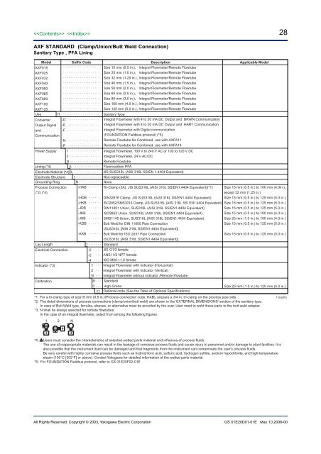
28<strong>AXF</strong> STANDARD (Clamp/Union/Butt Weld Connection)Sanitary Type , PFA LiningModel Suffix Code Description Applicable Model<strong>AXF</strong>015<strong>AXF</strong>025<strong>AXF</strong>032<strong>AXF</strong>040<strong>AXF</strong>050<strong>AXF</strong>065<strong>AXF</strong>080<strong>AXF</strong>100<strong>AXF</strong>125UseConverterOutput SignalandCommunicationPower Supply-D · · · · · · · · · · · · · · · · ·-E · · · · · · · · · · · · · · · · ·-F · · · · · · · · · · · · · · · · ·-N · · · · · · · · · · · · · · · · ·-P · · · · · · · · · · · · · · · · ·Sanitary TypeIntegral Flowmeter with 4 to 20 mA DC Output and BRAIN CommunicationIntegral Flowmeter with 4 to 20 mA DC Output and HART CommunicationIntegral Flowmeter with Digital communication(FOUNDATION Fieldbus protocol) (*5)Remote Flowtube for Combined use with <strong>AXF</strong>A11Remote Flowtube for Combined use with <strong>AXF</strong>A14Integral Flowmeter, 100 V to 240 V AC or 100 to 120 V DCIntegral Flowmeter, 24 V AC/DCRemote FlowtubeLining (*4)A · · · · · · · · · · · · · · Fluorocarbon PFAElectrode Material (*4) L · · · · · · · · · · · · · JIS SUS316L (AISI 316L SS/EN 1.4404 Equivalent)Electrode Structure 1 · · · · · · · · · · · · · · Non-replaceableGrounding Ring N · · · · · · · · · · · · NoneProcess Connection -HAB · · · · · · Tri-Clamp (3A), JIS SUS316L (AISI 316L SS/EN1.4404 Equivalent)(*1) Size 15 mm (0.5 in.) to 100 mm (4.0in.),(*2) (*4)except 32 mm (1.25 in.)-HDB · · · · · · DIN32676 Clamp, JIS SUS316L (AISI 316L SS/EN1.4404 Equivalent) Size 15 mm (0.5 in.) to 125 mm (5.0 in.)-HKB · · · · · · ISO2852/SMS3016 Clamp, JIS SUS316L (AISI 316L SS/ EN1.4404 Equivalent) Size 15 mm (0.5 in.) to 125 mm (5.0 in.)-JDB · · · · · · DIN11851 Union, SUS316L (AISI 316L SS/EN1.4404 Equivalent)Size 15 mm (0.5 in.) to 125 mm (5.0 in.)-JKB · · · · · · ISO2853 Union, SUS316L (AISI 316L SS/EN1.4404 Equivalent)Size 15 mm (0.5 in.) to 100 mm (4.0 in.)-JSB · · · · · · SMS1145 Union, SUS316L (AISI 316L SS/EN1.4404 Equivalent)Size 25 mm (1.0 in.) to 100 mm (4.0 in.)-KDB · · · · · · Butt Weld for DIN 11850 Pipe ConnectionSize 15 mm (0.5 in.) to 125 mm (5.0 in.)(SUS316L [AISI 316L SS/EN1.4404 Equivalent])-KKB · · · · · · Butt Weld for ISO 2037 Pipe ConnectionSize 15 mm (0.5 in.) to 125 mm (5.0 in.)(SUS316L [AISI 316L SS/EN1.4404 Equivalent])Lay Length 1 · · · · · · ·Electrical ConnectionIndicator (*3)· · · · · · · · · · · · · · · · · · · ·· · · · · · · · · · · · · · · · · · · ·· · · · · · · · · · · · · · · · · · · ·· · · · · · · · · · · · · · · · · · · ·· · · · · · · · · · · · · · · · · · · ·· · · · · · · · · · · · · · · · · · · ·· · · · · · · · · · · · · · · · · · · ·· · · · · · · · · · · · · · · · · · · ·· · · · · · · · · · · · · · · · · · · ·H · · · · · · · · · · · · · · · · · · · ·1 · · · · · · · · · · · · · · · ·2 · · · · · · · · · · · · · · · ·N · · · · · · · · · · · · · · · ·-0 · · · ·-2 · · · ·-4 · · · ·1 · · ·2 · · ·N · · ·Size 15 mm (0.5 in.), Integral Flowmeter/Remote FlowtubeSize 25 mm (1.0 in.), Integral Flowmeter/Remote FlowtubeSize 32 mm (1.25 in.), Integral Flowmeter/Remote FlowtubeSize 40 mm (1.5 in.), Integral Flowmeter/Remote FlowtubeSize 50 mm (2.0 in.), Integral Flowmeter/Remote FlowtubeSize 65 mm (2.5 in.), Integral Flowmeter/Remote FlowtubeSize 80 mm (3.0 in.), Integral Flowmeter/Remote FlowtubeSize 100 mm (4.0 in.), Integral Flowmeter/Remote FlowtubeSize 125 mm (5.0 in.), Integral Flowmeter/Remote FlowtubeStandardJIS G1/2 femaleANSI 1/2 NPT femaleISO M201.5 femaleIntegral Flowmeter with indicator (Horizontal)Integral Flowmeter with indicator (Vertical)Integral Flowmeter without indicator /Remote FlowtubeCalibrationB · · · StandardC · · · High GradeSize 25 mm (1.0 in.) to 125 mm (5.0 in.)/ Optional code (See the Table of Optional Specifications)*1: For a tri-clamp type of size15 mm (0.5 in.)(Process connection code: HAB), prepare a 3/4 in. tri-clamp on the process pipe side.T18.EPS*2: The detail dimensions of process connections (clamp/union/butt weld) are shown in the ‘EXTERNAL DIMENSIONS’ section of the sanitary type.In case of Butt Weld type, ferrules, sleeves, or alternative must be provided by the user. User need to weld these parts to the butt weld adapter.*3: N shall be always selected for remote flowtubes.In the case of an integral <strong>flowmeter</strong>, select from among the following figures.1 2 N*4: Users must consider the characteristics of selected wetted parts material and influence of process fluids.The use of inappropriate materials can result in the leakage of corrosive process fluids and cause injury to personnel and/or damage to plant facilities. It isalso possible that the instrument itself can be damaged and that fragments from the instrument can contaminate the user's process fluids.Be very careful with highly corrosive process fluids such as hydrochloric acid, sulfuric acid, hydrogen sulfide, sodium hypochlorite, and high-temperaturesteam (150°C [302°F] or above). Contact Yokogawa for detailed information of the wetted parts material.*5: For FOUNDATION Fieldbus protocol, refer to GS 01E20F02-01EAll Rights Reserved. Copyright © 2003, Yokogawa Electric <strong>Corp</strong>oration GS 01E20D01-01E May 10,2006-00
29REPLACEMENT MODEL FOR EARLIER ADMAG OR ADMAG AE (Wafer Type)General-purpose Use/Submersible Type/Explosion proof Type, PFA/Polyurethane Rubber LiningFor the Wafer Types of size 250 mm (10 in.), 300 mm (12 in.), <strong>AXF</strong> Standard shall be selected.UseModel Suffix Code Description Applicable Model<strong>AXF</strong>002<strong>AXF</strong>005<strong>AXF</strong>010<strong>AXF</strong>015<strong>AXF</strong>025<strong>AXF</strong>040<strong>AXF</strong>050<strong>AXF</strong>080<strong>AXF</strong>100<strong>AXF</strong>150<strong>AXF</strong>200ConverterOutput SignalandCommunicationPower SupplyLining (*9)Electrode Material (*9)Electrode StructureElectrical Connection (*6)Indicator (*4)(*7)Calibration· · · · · · · · · · · · · · · · · · · ·· · · · · · · · · · · · · · · · · · · ·· · · · · · · · · · · · · · · · · · · ·· · · · · · · · · · · · · · · · · · · ·· · · · · · · · · · · · · · · · · · · ·· · · · · · · · · · · · · · · · · · · ·· · · · · · · · · · · · · · · · · · · ·· · · · · · · · · · · · · · · · · · · ·· · · · · · · · · · · · · · · · · · · ·· · · · · · · · · · · · · · · · · · · ·· · · · · · · · · · · · · · · · · · · ·G · · · · · · · · · · · · · · · · · · · · ·W · · · · · · · · · · · · · · · · · · · · ·C · · · · · · · · · · · · · · · · · · · · ·-D · · · · · · · · · · · · · · · · · ·-E · · · · · · · · · · · · · · · · · ·-F · · · · · · · · · · · · · · · · · ·-N · · · · · · · · · · · · · · · · · ·-P · · · · · · · · · · · · · · · · · ·1 · · · · · · · · · · · · · · · ·2 · · · · · · · · · · · · · · · ·N · · · · · · · · · · · · · · · ·A · · · · · · · · · · · · · ·U · · · · · · · · · · · · · ·L · · · · · · · · · · · · ·P · · · · · · · · · · · · ·H · · · · · · · · · · · · ·T · · · · · · · · · · · · ·V · · · · · · · · · · · · ·W · · · · · · · · · · · · ·1 · · · · · · · · · · · ·-0 · · · ·-2 · · · ·-4 · · · ·1 · · ·2 · · ·N · · ·Size 2.5 mm (0.1 in.) Integral Flowmeter/Remote Flowtube (*8)Size 5 mm (0.2 in.) Integral Flowmeter/Remote Flowtube (*8)Size 10 mm (0.4 in.) Integral Flowmeter/Remote Flowtube (*8)Size 15 mm (0.5 in.) Integral Flowmeter/Remote Flowtube (*8)Size 25 mm (1.0 in.) Integral Flowmeter/Remote FlowtubeSize 40 mm (1.5 in.) Integral Flowmeter/Remote FlowtubeSize 50 mm (2.0 in.) Integral Flowmeter/Remote FlowtubeSize 80 mm (3.0 in.) Integral Flowmeter/Remote FlowtubeSize 100 mm (4.0 in.) Integral Flowmeter/Remote FlowtubeSize 150 mm (6.0 in.) Integral Flowmeter/Remote FlowtubeSize 200 mm (8.0 in.) Integral Flowmeter/Remote FlowtubeGeneral-Purpose UseSubmersible TypeExplosion proof Type (*5)Integral Flowmeter with 4 to 20 mA DC Output and BRAIN CommunicationIntegral Flowmeter with 4 to 20 mA DC Output and HART CommunicationIntegral Flowmeter with Digital communication(FOUNDATION Fieldbus protocol) (*10)Remote Flowtube for Combined Use with <strong>AXF</strong>A11Remote Flowtube for Combined Use with <strong>AXF</strong>A14Integral Flowmeter, 100 V to 240 V AC or 100 to 120 V DCIntegral Flowmeter, 24 V AC/DCRemote FlowtubeFluorocarbon PFAPolyurethane RubberJIS SUS316L (AISI 316L SS/EN 1.4404 Equivalent)Platinum-iridiumHastelloy C276 EquivalentTantalumTitaniumTungsten CarbideNon-replaceableGrounding Ring andGrounding ElectrodeMaterial (*9)N · · · · · · · · · · ·S · · · · · · · · · · ·L · · · · · · · · · · ·P · · · · · · · · · · ·H · · · · · · · · · · ·T · · · · · · · · · · ·V · · · · · · · · · · ·NoneJIS SUS316 (AISI 316 SS/EN 1.4401 Equivalent)JIS SUS316L (AISI 316L SS/EN 1.4404 Equivalent)Platinum-iridium (*8)Hastelloy C276 EquivalentTantalum (*8)TitaniumSize 25 mm (1.0 in.) to 200 mm (8.0 in.)(*5)PFA lining onlyPFA lining onlyProcess Connection (*3) -AA1 · · · · · · · ANSI Class 150 Wafer(*1)Size 2.5 mm (0.1 in.) to 200 mm (8.0 in.)-AA2 · · · · · · · ANSI Class 300Wafer(*1)Size 2.5 mm (0.1 in.) to 200 mm (8.0 in.)-AD1 · · · · · · · DIN PN 10Wafer(*2)Size 200 mm(8.0 in.) only-AD2 · · · · · · · DIN PN 16Wafer(*2)Size 80 mm (3.0 in.) to 200 mm (8.0 in.)-AD4 · · · · · · · DIN PN 40Wafer(*1)(*2)Size 2.5 mm (0.1 in.) to 50 mm (2.0 in.)-AJ1 · · · · · · · JIS 10KWafer(*1)Size 2.5 mm (0.1 in.) to 200 mm (8.0 in.)-AJ2 · · · · · · · JIS 20KWafer(*1)Size 2.5 mm (0.1 in.) to 200 mm (8.0 in.)-AG1 · · · · · · · JIS F12 (JIS75M) WaferSize 80 mm (3.0 in.) to 200 mm (8.0 in.)Lay Length 2 · · · · · · · Matches an Earlier ADMAG Flowmeter (ADMAG or ADMAG AE) for ReplacementJIS G1/2 femaleANSI 1/2 NPT femaleISO M201.5 femaleIntegral Flowmeter with indicator(Horizontal)Integral Flowmeter with indicator(Vertical)Integral Flowmeter without indicator /Remote FlowtubeB · · · StandardOptional code (See the Table of Optional Specifications)Not available for Submersible TypeNot available for Submersible Type/*1: For a wafer type of 2.5 to 10 mm (0.1 to 0.4 in.), prepare 15 mm (0.5 in.) diameter nominal flanges on the process pipe side.T19.EPS(Process connection codes: AA1, AA2, AD4, AJ1, and AJ2)*2: Even when DIN PN10 or 16 is required for a model of size 2.5 to 50 mm (0.1 to 2.0 in.), select PN40 (Process connection code: AD4) because there is nodifference in the dimensions of the mating faces.Even when DIN PN10 is required for a model of size 65 to 150 mm (2.5 to 6.0 in.), select PN16 (Process connection code: AD2) because there is no differencein the dimensions of the mating faces.*3: Mating dimensions are based on standards as follow:ANSI:ASME B 16.5, DIN: DIN 2501, JIS:JIS B 2220 and JIS G 3451*4: N shall be always selected for remote flowtubesIn the case of an integral <strong>flowmeter</strong>, select from among the figures at the right:1 2 NSize 15 mm (0.5 in.) to 200 mm (8.0 in.),Remote Flowtube onlyPFA lining onlySize 25 mm (1.0 in.) to 200 mm (8.0 in.)PFA lining onlyPFA lining only*5: For explosion proof types, specify types of explosion proof certification using the optional codes. In case of TIIS flameproof type, the remote flowtube is availableonly for combined use with the <strong>AXF</strong>A14. For the TIIS flameproof type with wiring using a flameproof packing adapter, select optional code G12 or G11. Availableonly for JIS G1/2 electrical connections.*6: JIS G1/2 Female electrical connection is available only for TIIS flameproof type.*7: In case of integral <strong>flowmeter</strong>s of the TIIS flameproof type, select “with indicator”(code 1 or 2).*8: In case of platinum-iridium (grounding ring code P) or tantalum (grounding ring code T) or None (grounding ring code N) in wafer type of 2.5 mm (0.1 in.) to 15mm (0.5 in.), the lay lengths of Replacement model are the same as those for <strong>AXF</strong> Standard.In this case, <strong>AXF</strong> Standard shall be selected.*9: Users must consider the characteristics of selected wetted parts material and influence of process fluids.The use of inappropriate materials can result in the leakage of corrosive process fluids and cause injury to personnel and/or damage to plant facilities. It isalso possible that the instrument itself can be damaged and that fragments from the instrument can contaminate the user's process fluids.Be very careful with highly corrosive process fluids such as hydrochloric acid, sulfuric acid, hydrogen sulfide, sodium hypochlorite, and high-temperaturesteam (150°C [302°F] or above). Contact Yokogawa for detailed information of the wetted parts material.*10:For FOUNDATION Fieldbus protocol, refer to GS 01E20F02-01EAll Rights Reserved. Copyright © 2003, Yokogawa Electric <strong>Corp</strong>oration GS 01E20D01-01E May 10,2006-00
- Page 1 and 2: GeneralSpecificationsGS 01E20D01-01
- Page 3 and 4: Functions “”How to Set Paramete
- Page 5 and 6: 5Size of AXF Flowtubes: AXF Standar
- Page 7 and 8: Flowtube Material:Size 2.5 mm (0.1
- Page 9 and 10: 9Gasket:Joints:UseLiningGeneral-Pur
- Page 11 and 12: CENELEC ATEX (KEMA):*AXF002C - AXF4
- Page 13 and 14: IECEx:*AXF002C - AXF400CApplicable
- Page 15 and 16: Polyurethane Rubber /Natural Soft R
- Page 17 and 18: ■ NORMAL OPERATING CONDITIONSAmbi
- Page 19 and 20: Fluid Temperature and Pressure:Note
- Page 21 and 22: Reasonable Figure for Thermal Shock
- Page 23 and 24: Size500 (20)600 (24)700 (28)800 (32
- Page 25 and 26: 25AXF STANDARD (Wafer /Union Joint
- Page 27: 27AXF STANDARD (Flange Type) Size 5
- Page 31 and 32: 31■ OPTIONAL SPECIFICATIONS FOR F
- Page 33 and 34: 33 Table of Optional Specifications
- Page 35 and 36: 35 Table of Optional Specifications
- Page 37 and 38: 37■ EXTERNAL DIMENSIONS AXF Stand
- Page 39 and 40: 39 AXF Standard, AXF015, Wafer Type
- Page 41 and 42: 41 AXF Standard, AXF002-AXF015, JIS
- Page 43 and 44: 43 AXF Standard, AXF065-AXF125, JIS
- Page 45 and 46: 45 AXF Standard, AXF250-AXF400, JIS
- Page 47 and 48: 47 AXF Standard, AXF015-AXF125, San
- Page 49 and 50: 49 Replacement model for Earlier AD
- Page 51 and 52: 51 Replacement model for Earlier AD
- Page 53 and 54: 53 AXF Standard, AXF11L-AXF13L, JIS
- Page 55 and 56: 55 Unless otherwise specified, diff