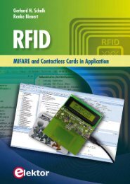
Practical Digital Signal Processing using Microcontrollers - Elektor
Practical Digital Signal Processing using Microcontrollers - Elektor
Practical Digital Signal Processing using Microcontrollers - Elektor
You also want an ePaper? Increase the reach of your titles
YUMPU automatically turns print PDFs into web optimized ePapers that Google loves.
<strong>Practical</strong> <strong>Digital</strong> <strong>Signal</strong> <strong>Processing</strong> <strong>using</strong><br />
<strong>Microcontrollers</strong><br />
Prof Dr Dogan Ibrahim<br />
Near East University
ACKNOWLEDGEMENTS<br />
The following material is reproduced in this book with the kind permission of the<br />
respective copyright holders and may not be reprinted, or reproduced in any way, without<br />
their prior consent.<br />
Figures A.1 – A.11 are taken from Microchip Technology Inc. Data Sheet<br />
PIC18(L)F2X/4XK22 (DS41412F). Figures 3.1 – 3.3, 3.9, 12.4 are taken from the web site<br />
of Microchip Technology Inc.<br />
Figure 3.4 is taken from the web site of Custom Computer Services Inc.<br />
Figures 3.6 – 3.8, 12.2, 12.4 are taken from the web site of mikroElektronica.<br />
Figure 3.5 is taken from the web site of Olimex.<br />
Figures 3.10 - 3.12, 14.1 – 14.3 are taken from the web site of Analog Devices Inc.<br />
Figure 3.13 is taken from the web site of Texas Instruments Inc.<br />
Figure 3.14 is taken from the web site of Freescale Semiconductors Inc.<br />
Copyright <strong>Elektor</strong><br />
PIC®, PICSTART®, and MPLAB® are all trademarks of Microchip Technology Inc.
Contents<br />
CHAPTER 1 -<br />
INTRODUCTION ........................................................................... 17<br />
1.1 BACKGROUND ....................................................................................................... 17<br />
1.2 A TYPICAL DSP APPLICATION ................................................................................... 18<br />
1.3 THE ANTI-ALIASING ANALOG FILTER ........................................................................... 18<br />
1.4 SAMPLE AND HOLD CIRCUIT ..................................................................................... 21<br />
1.5 A/D CONVERTER ................................................................................................... 21<br />
1.6 DSP ................................................................................................................... 24<br />
1.7 D/A CONVERTER ................................................................................................... 24<br />
1.8 EXERCISES ............................................................................................................ 25<br />
CHAPTER 2 -<br />
NUMBER SYSTEMS ...................................................................... 27<br />
2.1 FIXED POINT NUMBERS ........................................................................................... 27<br />
2.1.1 Decimal Number System ............................................................................ 28<br />
2.1.2 Binary Number System .............................................................................. 28<br />
2.1.3 Octal Number System ................................................................................ 29<br />
2.1.4 Hexadecimal Number System .................................................................... 29<br />
2.1.5 Converting Binary Numbers into Decimal .................................................. 30<br />
2.1.6 Converting Decimal Numbers into Binary .................................................. 31<br />
2.1.7 Converting Binary Numbers into Hexadecimal ........................................... 33<br />
2.1.8 Converting Hexadecimal Numbers into Binary ........................................... 34<br />
2.1.9 Converting Hexadecimal Numbers into Decimal ........................................ 35<br />
2.1.10 Converting Decimal Numbers into Hexadecimal ........................................ 36<br />
2.1.11 Converting Octal Numbers into Decimal .................................................... 37<br />
2.1.12 Converting Decimal Numbers into Octal .................................................... 38<br />
2.1.13 Converting Octal Numbers into Binary ....................................................... 39<br />
2.1.14 Converting Binary Numbers Into Octal ....................................................... 40<br />
2.1.15 Negative Numbers ..................................................................................... 40<br />
2.1.16 Adding Binary Numbers ............................................................................. 42<br />
2.1.17 Subtracting Binary Numbers ...................................................................... 43<br />
2.1.18 Multiplication of Binary Numbers .............................................................. 43<br />
2.1.19 Division of Binary Numbers ........................................................................ 45<br />
2.1.20 Signed Magnitude Representation ............................................................. 45<br />
2.1.21 Offset Binary Representation ..................................................................... 46<br />
Copyright <strong>Elektor</strong><br />
5
2.1.22 Fractional Fixed Point Numbers ................................................................. 47<br />
2.1.23 Converting Fractional Number into Integer ................................................ 48<br />
2.1.24 Converting from Integer into Fractional Number ....................................... 48<br />
2.2 FLOATING POINT NUMBERS ..................................................................................... 49<br />
2.2.1 Converting a Floating Point Number into Decimal ..................................... 50<br />
2.2.2 Normalizing the Floating Point Numbers ................................................... 51<br />
2.2.3 Converting a Decimal Number into Floating Point ..................................... 52<br />
2.2.4 Multiplication and Division of Floating Point Numbers............................... 53<br />
2.2.5 Addition and Subtraction of Floating Point Numbers ................................. 55<br />
2.3 FIXED POINT OR FLOATING POINT NUMBERS IN DSP OPERATIONS .................................... 56<br />
2.4 BCD NUMBERS ..................................................................................................... 57<br />
2.5 THE ASCII TABLE ................................................................................................... 58<br />
2.6 SUMMARY ........................................................................................................... 59<br />
2.7 EXERCISES ............................................................................................................ 60<br />
CHAPTER 3 -<br />
DIGITAL SIGNAL PROCESSORS ............................................... 65<br />
3.1 CHOOSING A DDSP PROCESSOR ............................................................................... 66<br />
3.2 DSP HARDWARE DEVELOPMENT TOOLS ..................................................................... 68<br />
3.2.1 General Purpose Microcontroller Development Tools ................................ 68<br />
3.2.2 DSP-Enhanced Processor Development Tools ............................................. 75<br />
3.2.3 Dedicated DSP Processor Development Tools ............................................ 80<br />
3.3 DSP SOFTWARE DEVELOPMENT TOOLS ...................................................................... 83<br />
3.3.1 General Purpose Microcontroller Software Development Tools ................. 83<br />
3.3.2 DSP-Enhanced Processor Software Development Tools .............................. 84<br />
3.3.3 Dedicated DSP Processor Software Development Tools.............................. 85<br />
3.4 EXERCISES ............................................................................................................ 86<br />
Copyright <strong>Elektor</strong><br />
CHAPTER 4 -<br />
MIKROC PRO PROGRAMMING LANGUAGE FOR<br />
MICROCONTROLLERS .................................................................. 87<br />
4.1 C LANGUAGES FOR MICROCONTROLLERS ..................................................................... 87<br />
4.2 YOUR FIRST MIKROC PRO FOR PIC PROGRAM .............................................................. 89<br />
4.2.1 Comments ................................................................................................. 90<br />
4.2.2 Beginning and Ending a Program .............................................................. 90<br />
4.2.3 White Spaces ............................................................................................. 91<br />
4.2.4 Variable Names ......................................................................................... 92<br />
4.2.5 Reserved Names ........................................................................................ 92<br />
4.2.6 Variable Types ........................................................................................... 93<br />
6
4.2.7 Constants .................................................................................................. 95<br />
4.2.8 Escape Sequences ...................................................................................... 96<br />
4.2.9 Accessing Bits of a Variable ....................................................................... 96<br />
4.2.10 sbit Type .................................................................................................... 97<br />
4.2.11 bit Type ..................................................................................................... 97<br />
4.2.12 Arrays ........................................................................................................ 97<br />
4.2.13 Pointers ................................................................................................... 100<br />
4.2.14 Structures ................................................................................................ 102<br />
4.2.15 Operators in mikroC Pro for PIC ............................................................... 105<br />
4.2.16 The Flow of Control ................................................................................. 109<br />
4.3 FUNCTIONS IN MIKROC PRO FOR PIC ....................................................................... 118<br />
4.3.1 void Functions ......................................................................................... 119<br />
4.3.2 Passing Parameters to Functions ............................................................. 119<br />
4.3.3 Passing Arrays to Functions ..................................................................... 120<br />
4.3.4 Interrupt <strong>Processing</strong> ................................................................................ 121<br />
4.4 MIKROC PRO FOR PIC BUILT-IN FUNCTIONS ............................................................... 122<br />
4.5 MIKROC PRO FOR PIC LIBRARIES ............................................................................. 123<br />
4.6 USING THE MIKROC PRO FOR PIC COMPILER.............................................................. 124<br />
4.6.1 mikroC Pro for PIC IDE ............................................................................. 125<br />
4.6.2 Creating a New Source File ...................................................................... 127<br />
4.6.3 Compiling the Source File......................................................................... 130<br />
4.7 SUMMARY ......................................................................................................... 131<br />
4.8 EXERCISES .......................................................................................................... 132<br />
CHAPTER 5 -<br />
Copyright <strong>Elektor</strong><br />
INTRODUCTION TO MATLAB ................................................. 135<br />
5.1 GETTING STARTED ............................................................................................... 135<br />
5.1.1 disp Command ........................................................................................ 137<br />
5.1.2 format Command .................................................................................... 138<br />
5.1.3 input Command ....................................................................................... 139<br />
5.1.4 Comment lines......................................................................................... 139<br />
5.1.5 Programming in MATLAB ........................................................................ 139<br />
5.1.6 The Working Environment ....................................................................... 149<br />
5.1.7 Vectors in MATLAB .................................................................................. 149<br />
5.1.8 Matrices in MATLAB ................................................................................ 154<br />
5.1.9 Graphics Plotting Using MATLAB ............................................................. 157<br />
5.2 SUMMARY ......................................................................................................... 170<br />
5.3 EXERCISES .......................................................................................................... 170<br />
7
CHAPTER 6 -<br />
DISCRETE TIME SIGNALS ....................................................... 173<br />
6.1 THE SAMPLING PROCESS ....................................................................................... 173<br />
6.2 SOME DIGITAL SIGNAL TYPES.................................................................................. 174<br />
6.2.1 Unit Step Function ................................................................................... 174<br />
6.2.2 Unit Impulse Function .............................................................................. 175<br />
6.2.3 Sinusoidal <strong>Signal</strong> ...................................................................................... 175<br />
6.2.4 Exponential <strong>Signal</strong> ................................................................................... 177<br />
6.2.5 Complex Exponential <strong>Signal</strong> ..................................................................... 177<br />
6.2.6 Exponential Sinusoidal Decay <strong>Signal</strong> ........................................................ 178<br />
6.3 OPERATIONS ON DISCRETE TIME SIGNALS .................................................................. 179<br />
6.3.1 Delay or Shift ........................................................................................... 179<br />
6.3.2 Vector Addition and Subtraction .............................................................. 181<br />
6.3.3 Scalar Addition and Subtraction .............................................................. 182<br />
6.3.4 Scalar Multiplication and Division ............................................................ 182<br />
6.3.5 Vector Multiplication and Division ........................................................... 183<br />
6.4 BLOCK DIAGRAM REPRESENTATION.......................................................................... 184<br />
6.4.1 Block Diagram Manipulation ................................................................... 184<br />
6.5 DISCRETE SYSTEM CLASSIFICATION ........................................................................... 186<br />
6.5.1 Linear and Non-linear .............................................................................. 186<br />
6.5.2 Time-variant and Time-invariant ............................................................. 186<br />
6.5.3 Causal and Non-causal ............................................................................ 186<br />
6.5.4 Stable and Unstable ................................................................................ 187<br />
6.5.5 Linear Time-invariant Systems ................................................................. 187<br />
6.6 THE CONVOLUTION PROCESS .................................................................................. 187<br />
6.7 EXERCISES .......................................................................................................... 192<br />
Copyright <strong>Elektor</strong><br />
CHAPTER 7 -<br />
THE Z-TRANSFORM .................................................................. 195<br />
7.1 UNIT STEP FUNCTION ........................................................................................... 195<br />
7.2 UNIT RAMP FUNCTION.......................................................................................... 196<br />
7.3 EXPONENTIAL FUNCTION ....................................................................................... 197<br />
7.4 SINE FUNCTION ................................................................................................... 198<br />
7.5 DISCRETE IMPULSE FUNCTION ................................................................................. 199<br />
7.6 TABLES OF Z-TRANSFORMS .................................................................................... 199<br />
7.7 THE Z-TRANSFORM OF A FUNCTION EXPRESSED AS A LAPLACE TRANSFORM ....................... 200<br />
7.8 PROPERTIES OF THE Z-TRANSFORM .......................................................................... 201<br />
7.9 INVERSE Z-TRANSFORMS ....................................................................................... 204<br />
7.9.1 Coefficients of Partial Fraction Expansion ................................................ 211<br />
8
7.10 EXERCISES .......................................................................................................... 214<br />
CHAPTER 8 -<br />
THE DISCRETE FOURIER TRANSFORM ............................... 217<br />
8.1 THE SPECTRA OF PERIODIC SIGNALS ......................................................................... 217<br />
8.2 PROPERTIES OF THE DFT ....................................................................................... 231<br />
8.3 FOURIER TRANSFORM OF APERIODIC DIGITAL SIGNALS ................................................. 232<br />
8.4 EXERCISES .......................................................................................................... 235<br />
CHAPTER 9 -<br />
DIGITAL FILTERS ...................................................................... 237<br />
9.1 FIR FILTERS AND IIR FILTERS .................................................................................. 238<br />
9.2 THE DIGITAL FILTER DESIGN PROCESS ....................................................................... 239<br />
CHAPTER 10 -<br />
DESIGN OF FIR DIGITAL FILTERS ........................................ 245<br />
10.1 THE FOURIER TRANSFORM METHOD ........................................................................ 245<br />
10.2 TRUNCATION AND WINDOWING.............................................................................. 249<br />
10.3 SOME COMMONLY USED WINDOWING FUNCTIONS ..................................................... 250<br />
10.3.1 Rectangular Window ............................................................................... 250<br />
10.3.2 Hamming Window................................................................................... 252<br />
10.3.3 Hanning Window ..................................................................................... 256<br />
10.3.4 Blackman Window................................................................................... 256<br />
10.3.5 Remez Exchange Based Design ................................................................ 260<br />
10.4 USING COMPUTER AIDED TECHNIQUES FOR THE DESIGN OF FIR FILTERS .......................... 260<br />
10.4.1 The ScopeFIR Software ............................................................................ 260<br />
10.5 FIR DIGITAL FILTER STRUCTURES ............................................................................. 268<br />
10.5.1 Direct FIR Structures ................................................................................ 268<br />
10.5.2 Cascade FIR Structures ............................................................................ 269<br />
10.6 EXERCISES .......................................................................................................... 269<br />
Copyright <strong>Elektor</strong><br />
CHAPTER 11 -<br />
DESIGN OF IIR DIGITAL FILTERS ......................................... 271<br />
11.1 IIR FILTER TRANSFER FUNCTION .............................................................................. 271<br />
11.2 ANALOG FILTER DESIGN REVIEW ............................................................................. 272<br />
11.3 BUTTERWORTH FILTERS ......................................................................................... 273<br />
11.3.1 Bilinear transformation method .............................................................. 275<br />
11.4 CHEBYSHEV FILTERS.............................................................................................. 282<br />
11.5 ELLIPTIC FILTERS .................................................................................................. 286<br />
11.6 THE SCOPEIIR FILTER DESIGN PROGRAM................................................................... 288<br />
11.7 IIR FILTER STRUCTURES ......................................................................................... 289<br />
11.7.1 Direct Structure ....................................................................................... 290<br />
9
11.7.2 Cascade Structure .................................................................................... 290<br />
11.8 EXERCISES .......................................................................................................... 292<br />
CHAPTER 12 -<br />
DESIGN OF FIR DIGITAL FILTERS USING<br />
MICROCONTROLLERS ................................................................ 295<br />
12.1 DESIGN OF A LOW-PASS FILTER ............................................................................... 295<br />
12.1.1 The Project Hardware .............................................................................. 295<br />
12.1.2 Calculating the Filter Coefficients with Scope FIR Filter Design Program .. 301<br />
12.1.3 Implementing the FIR Filter ..................................................................... 304<br />
12.1.4 The Algorithm.......................................................................................... 305<br />
12.1.5 Program Listing ....................................................................................... 306<br />
12.2 DESIGN OF A BAND-PASS FILTER ............................................................................. 310<br />
12.3 MORE EFFICIENT ALGORITHM ................................................................................. 311<br />
12.3.1 Filter Specifications.................................................................................. 315<br />
12.4 DESIGNING A BAND-PASS FILTER WITH MORE EFFICIENT ALGORITHM .............................. 318<br />
12.5 CALCULATING THE TIME IN THE FIR FILTER LOOP......................................................... 320<br />
CHAPTER 13 - DESIGN OF IIR DIGITAL FILTERS USING<br />
MICROCONTROLLERS ................................................................ 323<br />
13.1 DESIGN OF A LOW-PASS FILTER ............................................................................... 323<br />
13.1.1 The Project Hardware .............................................................................. 323<br />
13.1.2 Cascade Implementation ......................................................................... 324<br />
13.1.3 The Filter Coefficients .............................................................................. 326<br />
13.1.4 The Filter Program ................................................................................... 328<br />
13.2 SECOND ORDER HIGH-PASS FILTER .......................................................................... 331<br />
13.3 SIXTH ORDER LOW-PASS FILTER .............................................................................. 332<br />
13.4 PROGRAM FOR ANY EVEN ORDER IIR FILTER .............................................................. 335<br />
13.5 IIR FILTERS OF ANY ORDER .................................................................................... 337<br />
13.6 CALCULATING THE TIME IN THE IIR FILTER LOOP ......................................................... 341<br />
Copyright <strong>Elektor</strong><br />
CHAPTER 14 -<br />
GETTING STARTED WITH DEDICATED DSPS ..................... 343<br />
14.1 THE DEDICATED DSP MARKET ................................................................................ 343<br />
14.2 THE ADSP-21469 DSP PROCESSOR ....................................................................... 344<br />
14.3 THE ADSP-21469 EZ-BOARD DEVELOPMENT KIT ...................................................... 347<br />
14.4 AUDIO INPUT-OUTPUT CONNECTIONS ...................................................................... 351<br />
14.5 THE SHARC FAMILY DEVELOPMENT TOOLS ............................................................... 353<br />
14.6 THE VISUALDSP++ .............................................................................................. 356<br />
10
APPENDIX A BUTTERWORTH DIGITAL FILTER COEFFICIENTS .......... 365<br />
APPENDIX B CHEBYSHEV DIGITAL FILTER COEFFICIENTS ................. 371<br />
APPENDIX C<br />
ARCHITECTURE OF THE PIC18F45K22<br />
MICROCONTROLLER .................................................................. 377<br />
C.1 THE PIC18F45K22 MICROCONTROLLER .................................................................. 377<br />
C.2 PIC18F45K22 ARCHITECTURE ............................................................................... 378<br />
C.2.1 The Program Memory ............................................................................. 380<br />
C.2.2 The Data Memory ................................................................................... 381<br />
C.2.3 Oscillator Configurations ......................................................................... 382<br />
C.2.4 The Reset ................................................................................................. 382<br />
C.2.5 Parallel I/O Ports ..................................................................................... 383<br />
C.2.6 Timer Modules ........................................................................................ 384<br />
C.2.7 Analog-to-<strong>Digital</strong> Converter Module ........................................................ 387<br />
C.2.8 Interrupts ................................................................................................ 391<br />
APPENDIX D PROGRAM LISTING FIR1.C ..................................................... 397<br />
APPENDIX E PROGRAM LISTING FIR1.C (INPUT BUFFER) ...................... 401<br />
APPENDIX F PROGRAM LISTING IIR1.C ...................................................... 405<br />
APPENDIX G 6 TH ORDER IIR DIGITAL FILTER PROGRAM ....................... 409<br />
APPENDIX H PROGRAM LISTING EVEN NUMBER IIR FILTER ............... 413<br />
APPENDIX I PROGRAM LISTING: MODIFIED IIR FILTER DESIGN ....... 417<br />
Copyright <strong>Elektor</strong><br />
INDEX .......................................................................................................................... 423<br />
11
PREFACE<br />
<strong>Digital</strong> <strong>Signal</strong> <strong>Processing</strong> (DSP) is the process of capturing, analysing, and manipulation of<br />
an analog signal by a digital processor, e.g. a digital computer.<br />
The theory of DSP is quite complex and requires good understanding of high level of<br />
mathematics. Students new to DSP are usually taught the theory in great detail with very<br />
little or no practical applications. For example, in many cases a student can derive complex<br />
equations for digital filters, but is unable to implement a digital filter in real life. Some<br />
institutions use tools such as MATLAB to derive the coefficients of digital filters and then<br />
to simulate the behaviour of these filters on a PC. Although simulation can be an invaluable<br />
tool in teaching, it is never the same as real-time and real-life implementations.<br />
The aim of this book is to teach the basic principles of DSP and to introduce DSP from a<br />
practical point of view <strong>using</strong> minimum of mathematics. Only the basic level of theory is<br />
given just enough to implement DSP applications in real-time. The emphasis of the book is<br />
on practical aspects of DSP, such as design issues and real-time implementation issues. The<br />
practical implementation is described <strong>using</strong> the widely available low-cost general purpose<br />
microcontrollers so that the readers can very easily and quickly design and implement DSP<br />
applications in real-time. The architectures of dedicated DSP processors are complex and<br />
this adds additional difficulty to students who may want to implement DSP applications<br />
<strong>using</strong> such tools.<br />
In this book the popular and highly powerful PIC18F45K22 microcontroller is used as the<br />
processor to implement DSP applications in real-time. Using this microcontroller the<br />
readers should be able to implement DSP applications with sampling frequencies within the<br />
audio range. Programming is done <strong>using</strong> the popular and powerful mikroC PRO for PIC,<br />
which is a “C” language and compiler developed specifically for the PIC family of<br />
microcontrollers. The DSP projects given in the book are based on <strong>using</strong> the EasyPIC 7<br />
microcontroller development kit, although any other development kit could also be used.<br />
Copyright <strong>Elektor</strong><br />
The DSP development environment used in the book consists of:<br />
• EasyPIC 7 microcontroller development board with PIC18F45K22 chip<br />
• A/D converter (built-in on the microcontroller chip)<br />
• D/A converter (MCP4921)<br />
• PCSGU250 Frequency generator and Bode plotter<br />
• mikroC PRO for PIC compiler<br />
This book is primarily intended for students and practising engineers who may want to<br />
learn the practical implementation of DSPs, such as digital filters in real-time.<br />
13
The structure of the book is as follows:<br />
Chapter 1 is an introduction to the world of DSPs and gives a brief overview of the basic<br />
parts forming a typical DSP system.<br />
Chapter 2 is about the important topic of number systems which describes the various<br />
number systems used in microcontroller and DSP applications.<br />
Chapter 3 is an introduction to the processor architectures used in DSP applications. The<br />
features of various hardware and software development tools are given in this chapter.<br />
Chapter 4 is about “C” programming and describes the features of the popular mikroC PRO<br />
for PIC language and compiler in detail and with many examples.<br />
Chapter 5 is an introduction to the powerful engineering design and simulation tool<br />
MATLAB. The basic programming and graph plotting details are given with examples.<br />
Chapter 6 provides the basic principles of discrete time systems required for the<br />
understanding of DSP systems in general.<br />
Chapter 7 is about the z-transforms and covers the principles of this important topic,<br />
including the inverse transformations.<br />
Chapter 8 is an introduction to the important topic of Discrete Fourier Transforms and gives<br />
examples of finding the transform of some common functions.<br />
Chapter 9 is about the features of digital filters and provides a comparison of various types<br />
of filters used in practice.<br />
Copyright <strong>Elektor</strong><br />
Chapter 10 provides the theory of designing FIR digital filters. The design of low-pass and<br />
high-pass filters is given with examples. In addition, the ScopeFIR digital filter design<br />
software package is described with examples.<br />
Chapter 11 provides the theory of designing IIR digital filters. The design of Butterworth<br />
and Chebyshev type digital filters are given with examples. In addition, the ScopeIIR<br />
digital filter design software package is described with examples.<br />
Chapter 12 is about the implementation of FIR digital filters <strong>using</strong> general purpose<br />
microcontrollers. Various tested and working example projects are given in this chapter,<br />
including the implementation of several different windowed designs.<br />
Chapter 13 is about the implementation of IIR digital filters <strong>using</strong> general purpose<br />
microcontrollers. Various tested and working examples are given in this chapter, including<br />
the implementation of Butterworth and Chebyshev type filters.<br />
14
Chapter 14 is an introduction to the dedicated DSP processors where the use of<br />
VisualDSP++ software package is given with a simple example.<br />
Finally, Appendix A and Appendix B give tables for the design of Butterworth and<br />
Chebyshev type digital filters respectively. Appendix C provides the architectural details of<br />
the PIC18F45K22 microcontroller used in the projects in this book. Appendix D to<br />
Appendix I give program listings of designed digital filters.<br />
Prof Dr Dogan Ibrahim<br />
London, 2013<br />
Copyright <strong>Elektor</strong><br />
15
6.4 | Block Diagram Representation<br />
6.4 Block Diagram Representation<br />
Operations on discrete time sequences can be represented by <strong>using</strong> block diagrams<br />
as shown in Figure 6-14. Block diagrams can be useful when discrete time<br />
sequences are used in systems with discrete time inputs and outputs.<br />
Figure 6-14 Block diagram representation of discrete time sequences<br />
6.4.1 Block Diagram Manipulation<br />
Block diagram manipulation is useful for deriving the equations at various parts of<br />
the system. An example is given below.<br />
Copyright <strong>Elektor</strong><br />
Example 6.1<br />
The block diagram of a discrete time system is shown in Figure 6-15. Derive an<br />
expression for the output y[n].<br />
184
7.8 | Properties of the z-Transform<br />
Z[ax(n)] = aZ[x(n)] = aX[z]<br />
2. Left shift property<br />
Suppose that the z-transform of x[n] is X[z] and let y[n] = x(n + m). Then,<br />
m−1<br />
Y[z] = z m X[Z] − x(i)z m−i<br />
i=0<br />
If the initial conditions are all zero, i.e. x(i) = 0, i = 0,1,2,….,m-1, then,<br />
Z[x(n + m)] = z m X[z]<br />
3. Right shift property<br />
Suppose that the z-transform of x[n] is X[z] and let y[n] = x(n - m). Then,<br />
m−1<br />
Y[z] = z −m X[Z] − x(i − m)z −i<br />
i=0<br />
If the initial conditions are all zero, i.e. x(i) = 0, i = 0,1,2,….,m-1, then,<br />
Z[x(n − m)] = z − m X[z]<br />
4. Attenuation property<br />
Suppose that the z-transform of x[n] is X[z], then,<br />
Z[e −an x(n)] = X[ze a ]<br />
Copyright <strong>Elektor</strong><br />
This result states that if a function is multiplied by the exponential e −an<br />
then in the z-transform of this function z is replaced by ze a .<br />
5. Initial value theorem<br />
Suppose that the z-transform of x[n] is X[z], then the initial value of the<br />
time response is given by:<br />
lim x(n) = lim X[z]<br />
n→0 z→∞<br />
6. Final value theorem<br />
Suppose that the z-transform of x[n] is X[z], then the initial value of the<br />
time response is given by:<br />
lim x(n) = lim X[1 −<br />
n→∞ z→1 z−1 ]X[z]<br />
202
Chapter 10 - | Design of FIR <strong>Digital</strong> Filters<br />
Figure 10-2 shows a graph of the impulse response of the filter.<br />
Figure 10-2<br />
Impulse response of the filter<br />
In practice, it is impossible to realize a filter with the ideal characteristics of Figure<br />
10-1, as the impulse response is not causal and is of infinite length. In order to<br />
develop stable and realizable filters, the frequency response is relaxed and the sharp<br />
edges are removed and replaced with a transition band, and small ripple is allowed<br />
in the pass-band and stop band.<br />
Copyright <strong>Elektor</strong><br />
As seen from Figure 10-2, the impulse response decays to either side of the vertical<br />
axis, but is never 0. This is because we have defined the frequency response with<br />
very sharp edges. To realize the ideal filter we would need infinite number of<br />
impulse response coefficients which is not practical. In practice, the small sample<br />
values at the tails of the response are ignored and then h[n] is set to begin from n =<br />
0, so that we have a causal, realizable, linear phase filter. Typically depending upon<br />
the applications between 10 and 100 coefficients are taken in practical applications.<br />
10.2 Truncation and Windowing<br />
As we have seen in Example 10.1, the impulse response of an ideal filter has<br />
infinite number of coefficients and is not realizable. A finite length filter is obtained<br />
from the ideal response by setting all its coefficients to zero outside the range of<br />
− M ≤ n ≤ M , thus giving a filter with a length of N = 2 M + 1. If we then<br />
249
Chapter 13 - | Design of IIR <strong>Digital</strong> Filters <strong>using</strong> <strong>Microcontrollers</strong><br />
There are basically two methods that we can implement a second-order section in<br />
cascade and these are described below.<br />
In the first method the filter transfer function is assumed to be as follows:<br />
b + b z + b z<br />
H (13.1)<br />
−1<br />
−2<br />
0 1 2<br />
( z)<br />
=<br />
−1<br />
−2<br />
1+<br />
a1z<br />
+ a2<br />
z<br />
Using equation (13.1), the second order section is implemented as shown in Figure<br />
13-4, requiring 2 delays, 5 multiplications, and 2 summations.<br />
Figure 13-4<br />
Implementing a second order section<br />
In the second method, the transfer function is written as in equation (13.2) below.<br />
G(<br />
b + b z + b z )<br />
H (13.2)<br />
−1<br />
−2<br />
0 1 2<br />
( z)<br />
=<br />
−1<br />
−2<br />
1+<br />
a1z<br />
+ a2<br />
z<br />
Copyright <strong>Elektor</strong><br />
Where G is the gain and b 0 = 1 and equation (13.2) reduces to<br />
G(1<br />
+ b z + b z )<br />
H (13.3)<br />
−1<br />
−2<br />
1 2<br />
( z)<br />
=<br />
−1<br />
−2<br />
1+<br />
a1z<br />
+ a2<br />
z<br />
Figure 13-5 shows a second order filter implemented <strong>using</strong> the second method. The<br />
ScopeIIR digital filter design program gives the filter parameters as shown in Figure<br />
13-5.<br />
325
Index<br />
Index<br />
8<br />
8-Bit Mode, 384<br />
A<br />
Butterworth, 19, 271, 365<br />
Butterworth Filters, 273<br />
Butterworth Polynomials, 275<br />
C<br />
A/D converter, 21, 387<br />
A/D converters, 23<br />
Adding Binary Numbers, 42<br />
ADSP-21469 DSP Processor, 344<br />
ADSP-21469 EZ, 80<br />
ADSP-21469 EZ-Board, 347<br />
Analog Filter, 18<br />
Analog-to-digital converters, 173<br />
Anti-aliasing, 18<br />
Aperiodic <strong>Digital</strong> <strong>Signal</strong>s, 232<br />
Arithmetic format, 66<br />
Arrays, 97<br />
ASCII characters<br />
Extended, 59<br />
Standard, 59<br />
ASCII Table, 58<br />
Audio Blackfin, 78<br />
B<br />
Band-Pass Filter, 310<br />
band-pass filters, 237<br />
BCD numbers, 57<br />
Bessel, 19, 271<br />
Bilinear transformation, 275<br />
Binary Number System, 28<br />
Bit Fields, 104<br />
bit Type, 97<br />
Blackman Window, 256<br />
Bode plotter, 300<br />
Bode Plotter, 301<br />
Bookmarks, 125<br />
Built-in Functions, 122<br />
C language, 87<br />
Cascade FIR, 269<br />
Cascade Implementation, 324<br />
Cascade Structure, 290<br />
Causal, 186<br />
CCS C compiler, 88<br />
Character Arrays, 99<br />
Character Constants, 95<br />
Chebyshev, 19, 271, 371<br />
Chebyshev Filters, 282<br />
Code Assistant, 125<br />
Code Composer, 86<br />
Code Editor Window, 125<br />
Code Explorer Window, 126<br />
Code Template, 125, 126<br />
Comment lines, 139<br />
Comments, 90<br />
Complex Exponential <strong>Signal</strong>, 177<br />
Connector locations, 350<br />
const, 95<br />
Constant Strings, 100<br />
Constants, 95<br />
Converting Binary, 30, 33, 40<br />
Converting Decimal, 31, 36, 38<br />
Converting Hexadecimal, 34, 35<br />
Converting Octal, 37, 39<br />
Convolution Process, 187<br />
Cost and system complexity, 68<br />
CrossCore, 85<br />
Copyright <strong>Elektor</strong><br />
D<br />
D/A Converter, 24<br />
423
Data Memory, 381<br />
Data width, 67<br />
DDSP processor, 66<br />
Debug Agent, 359<br />
Decimal equivalent, 31<br />
Decimal Number System, 28<br />
Dedicated DSP, 85<br />
Dedicated DSP processors, 66<br />
Dedicated DSPs, 343<br />
Development time, 67<br />
DFT<br />
Differentiation, 232<br />
Linearity, 231<br />
Parseval's Relation, 232<br />
Periodicity, 231<br />
Real Sequences, 231<br />
Time delay, 232<br />
Diagram Manipulation, 184<br />
<strong>Digital</strong> Filters, 237<br />
frequency spectrum, 237<br />
<strong>Digital</strong> <strong>Signal</strong> <strong>Processing</strong>, 17<br />
<strong>Digital</strong> <strong>Signal</strong> Processors, 65<br />
<strong>Digital</strong>-to-analog converter, 173<br />
Direct FIR Structures, 268<br />
Direct Structure, 290<br />
Discrete Fourier Transform, 217<br />
Discrete Impulse Function, 199<br />
Discrete time signals, 173<br />
disp Command, 137<br />
Distinct real roots, 211<br />
Division of Binary Numbers, 45<br />
do – while Statements, 115<br />
DS1843, 21<br />
DSP, 24<br />
DSP algorithms, 56<br />
DSP Application, 18<br />
DSP applications, 195<br />
DSP Hardware, 68<br />
DSP-Enhanced Processor, 75<br />
DSP-enhanced processors, 66<br />
dsPIC33E Starter Kit, 77<br />
E<br />
Copyright <strong>Elektor</strong><br />
EasyPIC 7, 295, 296<br />
EasyPIC Fusion V7 Development Board,<br />
76<br />
EasyPIC V7 Development Board, 74<br />
Elliptic Filters, 286<br />
Escape Sequences, 96<br />
Even Order IIR Filter, 335<br />
EXOR, 53<br />
Exponential Function, 197<br />
Exponential signal, 177<br />
Extended ASCII characters, 59<br />
EZ-Kit Lite, 79<br />
F<br />
FFT implementations, 343<br />
Filter Algorithm, 326<br />
Filter Coefficients, 301, 326<br />
Filter order, 241, 273, 283<br />
Filter Program, 328<br />
Filter response, 239<br />
Filter Specifications, 315<br />
Filter type, 241<br />
FilterLab, 20<br />
Finite Impulse Response filter, 238<br />
FIR <strong>Digital</strong> Filters, 245<br />
FIR Filter Loop, 320<br />
FIR Filters, 238<br />
Fixed Point, 27<br />
Fixed Point Numbers, 27<br />
float, double, 94<br />
Floating Point, 27, 49<br />
Floating Point Constants, 95<br />
for Statements, 115<br />
format Command, 138<br />
Fourier Series, 217<br />
Fourier Transform, 232<br />
Fourier Transform Method, 245<br />
Fraction Expansion, 211<br />
424
Index<br />
Fractional Fixed Point Numbers, 47<br />
function declaration, 118<br />
G<br />
General purpose processors, 66<br />
goto Statement, 118<br />
Graphics Plotting, 157<br />
H<br />
Hamming Window, 252<br />
Hanning Window, 256<br />
Hexadecimal equivalent, 34<br />
Hexadecimal Number System, 29<br />
High-Pass Filter, 331<br />
high-pass filters, 237<br />
HS2420, 21<br />
I<br />
I/O Ports, 383<br />
IDE, 88<br />
IEEE 754, 27<br />
IIR <strong>Digital</strong> Filters, 271<br />
IIR Filter Loop, 341<br />
IIR Filter Structures, 289<br />
IIR filters, 371<br />
IIR Filters, 238, 337<br />
Illegal names, 92<br />
Impulse function, 175<br />
Infinite Impulse Response filters, 238<br />
input Command, 139<br />
Integer Constants, 95<br />
Interrupt <strong>Processing</strong>, 121<br />
Interrupts, 395<br />
Inverse z-Transforms, 204<br />
L<br />
Laplace transform, 195, 200<br />
LED connections, 361<br />
LEDs, 361<br />
LF398, 21<br />
Library Manager Window, 127<br />
Linear, 186<br />
Linear Time-invariant, 187<br />
Low-Pass Filter, 295, 323, 332<br />
M<br />
mantissa, 55<br />
MATLAB, 135<br />
matrix operations, 154<br />
MCP4921, 299<br />
Memory, 67<br />
Message Window, 126<br />
Microcontroller, 173, 377<br />
<strong>Microcontrollers</strong>, 295, 323<br />
mikroC PRO, 83, 84<br />
MPLAB C18, 84<br />
MSC8156ADS StarCore DSP, 82<br />
MT090, 21<br />
Multi-channel, 23<br />
Multi-dimensional array, 99<br />
Multiple order roots, 212<br />
Multiplication of Binary Numbers, 43<br />
Copyright <strong>Elektor</strong><br />
N<br />
Negative Numbers, 40<br />
New project window, 128<br />
Non-causal, 186<br />
Non-linear, 186<br />
non-recursive filters, 238<br />
Normalizing, 51<br />
Number Systems, 27<br />
O<br />
Octal equivalent, 38<br />
Octal Number System, 29<br />
425
Offset Binary, 46<br />
Operators, 105<br />
Arithmetic Operators, 105<br />
Bitwise, 107<br />
Conditional, 107<br />
Logical, 107<br />
Preprocessor, 108<br />
Relational, 107<br />
Oscillator Configurations, 382<br />
P<br />
R<br />
random noise, 23<br />
Rectangular Window, 250<br />
Remez Exchange, 260<br />
Repetition Statements, 113<br />
Reserved names, 92<br />
Reserved Names, 92<br />
Reset, 382<br />
S<br />
Parallel converters, 24<br />
Parameter Assistant, 125<br />
Passing Arrays, 120<br />
Passing Parameters, 119<br />
PCSGU250, 300<br />
Periodic <strong>Signal</strong>s, 217<br />
PIC Compiler, 124<br />
PIC IDE, 125<br />
PIC Libraries, 123<br />
PIC Program, 89<br />
PIC variable types, 93<br />
PIC18 Explorer Board, 69<br />
PIC18F45K22, 295, 297<br />
PIC18F45K22 Development Kit, 72<br />
PIC18F4XK20 Starter Kit, 70<br />
PICDEM 4 Demo Board, 71<br />
PIC-USB-STK Development Board, 73<br />
Pointer Arithmetic, 101<br />
Pointers, 100<br />
Power consumption, 68<br />
Program Memory, 380<br />
Project Hardware, 295<br />
Project Manager Window, 127<br />
Q<br />
Q-Format, 47<br />
quantization error, 23<br />
Sampling frequency, 243<br />
Sampling Process, 173<br />
sbit Type, 97<br />
Scalar addition, 182<br />
Scalar division, 182<br />
Scalar multiplication, 182<br />
Scalar subtraction, 182<br />
ScopeFIR, 260<br />
ScopeIIR Filter, 288<br />
Selection Statements, 109<br />
Shannon sampling theorem, 18<br />
Shannon theorem, 174<br />
SHARC family, 345<br />
signed char, 94<br />
signed long int, 94<br />
Signed Magnitude, 45<br />
Sine Function, 198<br />
Sinusoidal Decay, 178<br />
Sinusoidal function, 175<br />
Special Matrices, 156<br />
Speed, 67<br />
Stable, 187<br />
Standard ASCII characters, 59<br />
String Constants, 96<br />
String Operations, 101<br />
Strings, 99<br />
Structures, 102<br />
Subtracting Binary Numbers, 43<br />
Switch Selection Statements, 110<br />
Copyright <strong>Elektor</strong><br />
426
Index<br />
Symphony Studio, 86<br />
Syntax, 89<br />
System Classification, 186<br />
T<br />
Time-invariant, 186<br />
Timer Modules, 384<br />
Time-variant, 186<br />
TMS320C5416 DSP, 81<br />
Transfer Function, 271<br />
Truncation, 249<br />
Types<br />
Derived, 93<br />
Fundamental types, 93<br />
U<br />
Unit Ramp Function, 196<br />
Unit step function, 174<br />
Unit Step Function, 195<br />
unsigned int, 94<br />
unsigned long int, 94<br />
Unstable, 187<br />
V<br />
Variable Names, 92<br />
Variable Types, 93<br />
Vector Addition, 181<br />
Vector arithmetic operators, 153<br />
Vector division, 183<br />
Vector multiplication, 183<br />
Vector Subtraction, 181<br />
Vectors in MATLAB, 149<br />
Velleman PCSGU250, 295<br />
VisualDSP++, 356<br />
void, 90<br />
void Functions, 119<br />
W<br />
while Statement, 113<br />
White spaces, 91<br />
Windowing, 249<br />
Z<br />
z-Transform<br />
Attentuation property, 202<br />
Final value theorem, 202<br />
Initial value theorem, 202<br />
iztrans, 204<br />
Left shift property, 202<br />
Linearity property, 201<br />
Right shift property, 202<br />
Z-transform, 195<br />
Z-transforms tables, 199<br />
Copyright <strong>Elektor</strong><br />
427


