BOLENS 1969-1972 - Fairbanks Snow Travelers
BOLENS 1969-1972 - Fairbanks Snow Travelers
BOLENS 1969-1972 - Fairbanks Snow Travelers

You also want an ePaper? Increase the reach of your titles
YUMPU automatically turns print PDFs into web optimized ePapers that Google loves.
Bolens<br />
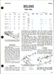
FI9. 5—Vi«w of •nglii* compaitment OH<br />
late mochln* showing points of adiustment.<br />
A. Chaincaw cover B. Adjuating screw<br />
C. Brak«untt<br />
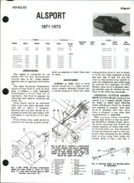
Fig. 8—ExplodMl vlow of<br />
chotn cose ond ossoclotod<br />
ports ttsod on modols with<br />
onclosod choin.<br />
1. Intermediate shaft<br />
2. Spacer<br />
3. Snap ring<br />
-I. Oil seal<br />
5. Bearing cone<br />
6. Bearing cup<br />
7. Adjusting screw<br />
8. Eccentric housing<br />
9. O-rlng<br />
10. Disc<br />
11. Drive sprocket<br />
12. Nut<br />
13. Upper cover<br />
14. Lower cover<br />
15. Snap ring<br />
16. Driven sprocket<br />
17. Chalncase<br />
18. Bearing<br />
19. on seal<br />
16<br />
14<br />
LEVER<br />
ADJUSTWSNT<br />
NUTS<br />
q<br />
lovor position<br />
Is adfvstod ot coblo<br />
onehor nuts. Woor odfustmont<br />
Is ol»tolnod by removing<br />
eotttr pin and<br />
turning castollatod nut to<br />
componsoto for woar*<br />
10<br />
ing cap screw (B) in eccentric housing.<br />
Push cap screw down in slot to<br />
tighten chain, or up to loosen. If cap<br />
screw bottoms in slot before slack is<br />
removed, install bolt in alternate<br />
threaded hole which has appeared at<br />
top of slot. Tighten cap screw securely<br />
and reinstall plastic plug when<br />
tension is correct.<br />
BRAKE. Friction disc for the caliper<br />
type disc brake is combined with<br />
the main drive (upper) sprocket<br />
on early models (see Fig. 6). Late<br />
models use fixed face of driven sheave<br />
as friction surface as shown at (C—<br />
Fig. 5).<br />
Brake should not drag when released<br />
but should fully engage before hand<br />
lever touches handlebar grip. To adjust<br />
for wear, remove cotter pin (Fig.<br />
6) and turn castellated nut until there<br />
is a slight drag on brake disc, back off<br />
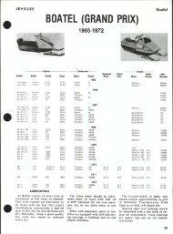
Fig. 7—To adiust track tonsion, raiso roar<br />
of mochlno and loosen clomp scrow nuts<br />
(11. Turn adiusting scrows (2) oqually until<br />
distance CD) is as outlined in toxt.<br />
38<br />
one notch and reinstall cotter pin.<br />
Hand lever travel is adjusted at the<br />
two anchor nuts.<br />
TRACK. To adjust track tension,<br />
raise rear of machine until track is<br />
clear of ground, then measure distance<br />
between running board and lowest<br />
point of swing arm as shown at<br />
(D—^Fig. 7). Measurement should be<br />
3-3% inches for <strong>1969</strong> models; four<br />
inches for 1970 models and as follows<br />
for 1971 machines:<br />
Models 295 & 340<br />
4% in.<br />
Model 292<br />
4H in.<br />
To adjust the track, loosen the two<br />
clamp bolts (1) and turn adjusting<br />
bolt (2) until measurement is correct.<br />
NOTE: Whenever track tension has<br />
been adjusted, alignment MUST be<br />
checked as outlined in TRACK SERV-<br />
ICE Section of this manual.<br />
1. Bolt •'>. Sprint cap<br />
2. Weight unit *>. Idler<br />
3. Moving flange 7. Flange & hub<br />
4. Spring<br />
9—Exploded view of centrifugal drive<br />
sheave used on <strong>BOLENS</strong> Sprint.<br />
12 11<br />
q. to—Exploded view of torque sensing<br />
driven sheave.<br />
1. O-ring<br />
2. Eccentric housing<br />
3. Bearing cup<br />
4. Bearing cone<br />
5. Oil seal<br />
6. Snap ring<br />
7. Spacer<br />
8. Hub<br />
9. Fixed flange<br />
10. Moving flange<br />
11. Floating hub<br />
12. Bushing<br />
13. Torque spring<br />
14. Nylon shoe<br />
15. Intermediate shaft<br />
16. Thrust washer<br />
17. Snap ring<br />
OVERHAUL<br />
SKIS. Steering skis, spindles and associated<br />
parts are interchangeable<br />
from right to left. Skis have renewable<br />
wear runners. Ski springs are<br />
equipped with a conical rubber<br />
bumper which should be installed to<br />
rear.<br />
IMPORTANT: DO NOT tighten<br />
locknut on bumper stud tight against<br />
spring leaf, or action of the spring will<br />
be restricted.<br />
TORQUE CONVERTER. Refer to<br />
Fig. 9 for an exploded view of torque<br />
converter drive sheave and to Fig.<br />
10 for driven sheave. Torque spring<br />
(13—Fig. 10) should be preloaded<br />
4 turn (one cam) when unit is<br />
assembled.