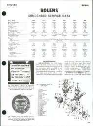
BOLENS 1969-1972 - Fairbanks Snow Travelers
BOLENS 1969-1972 - Fairbanks Snow Travelers
BOLENS 1969-1972 - Fairbanks Snow Travelers

Create successful ePaper yourself
Turn your PDF publications into a flip-book with our unique Google optimized e-Paper software.
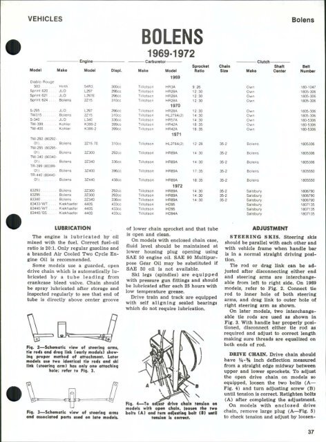
VEHICLES<br />
Model<br />
Make<br />
Engine<br />
Model<br />
Displ.<br />
<strong>BOLENS</strong><br />
Make<br />
<strong>1969</strong>-<strong>1972</strong><br />
Carburetor<br />
Model<br />
Sprocket<br />
Ratio<br />
Chain<br />
Size<br />
Make<br />
Clutch<br />
Shaft<br />
Center<br />
Bolens<br />
Beit<br />
Number<br />
Diablo Rouge<br />
503<br />
Hirth<br />
Sprint 620 ... JLO<br />
Sprint 621 . . . . JLO<br />
Sprint 624 .... Bolens<br />
S-295<br />
TW315<br />
S-340<br />
VAI-399<br />
TW-400<br />
TW-292 (80292-<br />
01)<br />
TW-295 (80295-<br />
01)<br />
TW-340 (80340-<br />
01)<br />
TR-399 (80399-<br />
01)<br />
TR-440 (80440-<br />
01)<br />
JLO<br />
Bolens<br />
JLO<br />
Kohler<br />
Kohler<br />
Bolens<br />
Bolens<br />
Bolens<br />
Bolens<br />
Bolens<br />
54R3.<br />
L297<br />
L297E<br />
2Z15<br />
L297<br />
2Z15<br />
L340<br />
K399-2<br />
K399-2<br />
2Z15.70<br />
2Z300<br />
2Z340<br />
3Z400<br />
3Z440<br />
300CC<br />
296CC<br />
296CC<br />
310CC<br />
296CC<br />
310cc<br />
336CC<br />
399CC<br />
399CC<br />
310CC<br />
292CC<br />
336CC<br />
396CC<br />
438CC<br />
Tillotson<br />
Tillotson<br />
Tillotson<br />
Tillotson<br />
Tillotson<br />
Tillotson<br />
Tillotson<br />
Tillotson<br />
Tillotson<br />
Tillotson<br />
Titlotson<br />
Tillotson<br />
Tillotson<br />
Tillotson<br />
<strong>1969</strong><br />
HR3A<br />
HR28A<br />
HR28A<br />
HR28A<br />
1970<br />
HR28A<br />
HL279A(2)<br />
HR57A<br />
HR42A<br />
HR42A<br />
1971<br />
HL279A(2)<br />
HR89A<br />
HR89A<br />
HR89A<br />
MR89A<br />
9:26<br />
12:30<br />
12:30<br />
12:30<br />
12:30<br />
14:30<br />
14:30<br />
18:35<br />
18:35<br />
12:28<br />
14:30<br />
14:30<br />
17:35<br />
18:35<br />
35-2<br />
35-2<br />
35-2<br />
35-2<br />
35-2<br />
Own<br />
Own<br />
Own<br />
Own<br />
Own<br />
Own<br />
Own<br />
Own<br />
Own<br />
Bolens<br />
Bolens<br />
Bolens<br />
Bolens<br />
Bolens<br />
180-1047<br />
1805-306<br />
1805-306<br />
1805-306<br />
1805-306<br />
1805-306<br />
180-5306<br />
180-5306<br />
180-5306<br />
1805306<br />
1805306<br />
1805306<br />
1805550<br />
1805550<br />
83293<br />
83295<br />
83340<br />
83433/WT ...<br />
83440/WT<br />
83440/SS<br />
Bolens<br />
Bolens<br />
Bolens<br />
Kiekhaefer<br />
Kiekhaefer<br />
Kiekhaefer<br />
2Z300<br />
2Z300<br />
2Z340<br />
440S<br />
440S<br />
440S<br />
292CC<br />
292CC<br />
336CC<br />
433CC<br />
433CC<br />
433CC<br />
Tillotson<br />
Tillotson<br />
Tillotson<br />
Tillotson<br />
Tillotson<br />
Tillotson<br />
<strong>1972</strong><br />
HR89A<br />
HR89A<br />
HR89A<br />
HD95<br />
HD95<br />
HO94A<br />
14:30<br />
14:30<br />
14:30<br />
35-2<br />
35-2<br />
35-2<br />
Salsbury<br />
Salsbury<br />
Salsbury<br />
Salsbury<br />
Salsbury<br />
Salsbury<br />
1806790<br />
1806790<br />
1806790<br />
1807135<br />
1807135<br />
1807135<br />
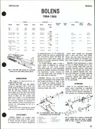
LUBRICATION<br />
The engine is lubricated by oil<br />
mixed with the fuel. Correct fuel-oil<br />
ratio is 20:1. Only regular gasoline and<br />
a branded Air Cooled Two Cycle Engine<br />
Oil is recommended.<br />
Some models use a guarded, open<br />
drive chain which is automatically lubricated<br />
by a tube leading from<br />
crankcase bleed valve. Chain should<br />
be spray lubricated after storage and<br />
inspected regularly to see that end of<br />
tube is directly above center groove<br />
Fig. 2—Schetnotic view of steering armt,<br />
tie rodf and drag iink (early modeis) showing<br />
proper method of oHachment. Loter<br />
modeis use two identicol tie rods and ski<br />
iink (steering arm) has oniy one attaching<br />
hole; refer to Fig. 3.<br />
Fig, 3—Schematic view of steering arms<br />
and associated parts us«d on late models.<br />
of lower chain sprocket and that tube<br />
is open and clean.<br />
On models with enclosed chain case,<br />
fluid level should be maintained at<br />
lower housing plug opening using<br />
SAE 50 engine oil. SAE 90 Multipurpose<br />
G^ar Oil may be substituted if<br />
SAE 50 oil is not available.<br />
Ski legs (spindles) are equipped<br />
with pressure gun fittings and should<br />
be lubricated after each 25 hours with<br />
low temperature grease.<br />
Drive train and track are equipped<br />
with self aligning sealed bearings<br />
which do not require lubrication.<br />
Fig. 4—To adlHst drlv* chain tension on<br />
modeis with open chain, ioosMi the two<br />
bolts (A) and tum adfusting bolt (B)<br />
ttnsion is correct.<br />
ADJUSTMENT<br />
STEERING SKIS. Steering skis<br />
should be parallel with each other and<br />
with vehicle frame when handle bar<br />
is in a normal straight driving position.<br />
Tie rod or drag link can be adjusted<br />
after disconnecting either end<br />
and steering arms are interchangeable<br />
from left to right side. On <strong>1969</strong><br />
models, refer to Fig. 2. Connect tie<br />
rod to inner hole of both steering<br />
arms, and drag link to outer hole of<br />
right steering arm as shown.<br />
On later models, two interchangeable<br />
tie rods are used as shown in<br />
Fig. 3. With handle bar properly positioned,<br />
disconnect either tie rod as<br />
required and adjust to correct length<br />
making sure threads are equalized on<br />
both ends of rod.<br />
DRIVE CHAIN. Drive chain should<br />
have V4'% inch deflection measured<br />
from a straight edge midway between<br />
upper and lower sprockets. To adjust<br />
the open drive chain on models so<br />
equipped, loosen the two bolts (A—<br />
Fig. 4) and turn adjusting screw (B)<br />
until tension is correct. Hetighten bolts<br />
(A) after completing the adjustment.<br />
On models with enclosed drive<br />
chain, remove large plug (A—Fig. 5)<br />
to check tension and adjust by loosen-<br />
37
Bolens<br />
FI9. 5—Vi«w of •nglii* compaitment OH<br />
late mochln* showing points of adiustment.<br />
A. Chaincaw cover B. Adjuating screw<br />
C. Brak«untt<br />
Fig. 8—ExplodMl vlow of<br />
chotn cose ond ossoclotod<br />
ports ttsod on modols with<br />
onclosod choin.<br />
1. Intermediate shaft<br />
2. Spacer<br />
3. Snap ring<br />
-I. Oil seal<br />
5. Bearing cone<br />
6. Bearing cup<br />
7. Adjusting screw<br />
8. Eccentric housing<br />
9. O-rlng<br />
10. Disc<br />
11. Drive sprocket<br />
12. Nut<br />
13. Upper cover<br />
14. Lower cover<br />
15. Snap ring<br />
16. Driven sprocket<br />
17. Chalncase<br />
18. Bearing<br />
19. on seal<br />
16<br />
14<br />
LEVER<br />
ADJUSTWSNT<br />
NUTS<br />
q<br />
lovor position<br />
Is adfvstod ot coblo<br />
onehor nuts. Woor odfustmont<br />
Is ol»tolnod by removing<br />
eotttr pin and<br />
turning castollatod nut to<br />
componsoto for woar*<br />
10<br />
ing cap screw (B) in eccentric housing.<br />
Push cap screw down in slot to<br />
tighten chain, or up to loosen. If cap<br />
screw bottoms in slot before slack is<br />
removed, install bolt in alternate<br />
threaded hole which has appeared at<br />
top of slot. Tighten cap screw securely<br />
and reinstall plastic plug when<br />
tension is correct.<br />
BRAKE. Friction disc for the caliper<br />
type disc brake is combined with<br />
the main drive (upper) sprocket<br />
on early models (see Fig. 6). Late<br />
models use fixed face of driven sheave<br />
as friction surface as shown at (C—<br />
Fig. 5).<br />
Brake should not drag when released<br />
but should fully engage before hand<br />
lever touches handlebar grip. To adjust<br />
for wear, remove cotter pin (Fig.<br />
6) and turn castellated nut until there<br />
is a slight drag on brake disc, back off<br />
Fig. 7—To adiust track tonsion, raiso roar<br />
of mochlno and loosen clomp scrow nuts<br />
(11. Turn adiusting scrows (2) oqually until<br />
distance CD) is as outlined in toxt.<br />
38<br />
one notch and reinstall cotter pin.<br />
Hand lever travel is adjusted at the<br />
two anchor nuts.<br />
TRACK. To adjust track tension,<br />
raise rear of machine until track is<br />
clear of ground, then measure distance<br />
between running board and lowest<br />
point of swing arm as shown at<br />
(D—^Fig. 7). Measurement should be<br />
3-3% inches for <strong>1969</strong> models; four<br />
inches for 1970 models and as follows<br />
for 1971 machines:<br />
Models 295 & 340<br />
4% in.<br />
Model 292<br />
4H in.<br />
To adjust the track, loosen the two<br />
clamp bolts (1) and turn adjusting<br />
bolt (2) until measurement is correct.<br />
NOTE: Whenever track tension has<br />
been adjusted, alignment MUST be<br />
checked as outlined in TRACK SERV-<br />
ICE Section of this manual.<br />
1. Bolt •'>. Sprint cap<br />
2. Weight unit *>. Idler<br />
3. Moving flange 7. Flange & hub<br />
4. Spring<br />
9—Exploded view of centrifugal drive<br />
sheave used on <strong>BOLENS</strong> Sprint.<br />
12 11<br />
q. to—Exploded view of torque sensing<br />
driven sheave.<br />
1. O-ring<br />
2. Eccentric housing<br />
3. Bearing cup<br />
4. Bearing cone<br />
5. Oil seal<br />
6. Snap ring<br />
7. Spacer<br />
8. Hub<br />
9. Fixed flange<br />
10. Moving flange<br />
11. Floating hub<br />
12. Bushing<br />
13. Torque spring<br />
14. Nylon shoe<br />
15. Intermediate shaft<br />
16. Thrust washer<br />
17. Snap ring<br />
OVERHAUL<br />
SKIS. Steering skis, spindles and associated<br />
parts are interchangeable<br />
from right to left. Skis have renewable<br />
wear runners. Ski springs are<br />
equipped with a conical rubber<br />
bumper which should be installed to<br />
rear.<br />
IMPORTANT: DO NOT tighten<br />
locknut on bumper stud tight against<br />
spring leaf, or action of the spring will<br />
be restricted.<br />
TORQUE CONVERTER. Refer to<br />
Fig. 9 for an exploded view of torque<br />
converter drive sheave and to Fig.<br />
10 for driven sheave. Torque spring<br />
(13—Fig. 10) should be preloaded<br />
4 turn (one cam) when unit is<br />
assembled.