ADT7467 - dbCOOL Remote Thermal Monitor and Fan Controller
ADT7467 - dbCOOL Remote Thermal Monitor and Fan Controller
ADT7467 - dbCOOL Remote Thermal Monitor and Fan Controller

You also want an ePaper? Increase the reach of your titles
YUMPU automatically turns print PDFs into web optimized ePapers that Google loves.
<strong>ADT7467</strong><br />
<strong>dbCOOL</strong> <strong>Remote</strong> <strong>Thermal</strong><br />
<strong>Monitor</strong> <strong>and</strong> <strong>Fan</strong> <strong>Controller</strong><br />
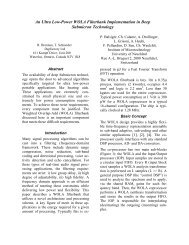
The <strong>ADT7467</strong> <strong>dbCOOL</strong> controller is a thermal monitor <strong>and</strong><br />
multiple PWM fan controller for noise-sensitive or power-sensitive<br />
applications requiring active system cooling. The <strong>ADT7467</strong> can drive<br />
a fan using either a low or high frequency drive signal, monitor the<br />
temperature of up to two remote sensor diodes plus its own internal<br />
temperature, <strong>and</strong> measure <strong>and</strong> control the speed of up to four fans so<br />
that they operate at the lowest possible speed for minimum acoustic<br />
noise.<br />
The automatic fan speed control loop optimizes fan speed for a<br />
given temperature. A unique dynamic TMIN control mode enables the<br />
system thermals/acoustics to be intelligently managed. The<br />
effectiveness of the system’s thermal solution can be monitored using<br />
the THERM input. The <strong>ADT7467</strong> also provides critical thermal<br />
protection to the system using the bidirectional THERM pin as an<br />
output to prevent system or component overheating.<br />
Features<br />
� Controls <strong>and</strong> <strong>Monitor</strong>s up to 4 <strong>Fan</strong>s<br />
� High <strong>and</strong> Low Frequency <strong>Fan</strong> Drive Signal<br />
� 1 On-chip <strong>and</strong> 2 <strong>Remote</strong> Temperature Sensors<br />
� Series Resistance Cancellation on the <strong>Remote</strong> Channel<br />
� Extended Temperature Measurement Range, up to 191�C<br />
� Dynamic TMIN Control Mode Intelligently Optimizes System<br />
Acoustics<br />
� Automatic <strong>Fan</strong> Speed Control Mode Manages System Cooling based<br />
on Measured Temperature<br />
� Enhanced Acoustic Mode Dramatically Reduces User Perception of<br />
Changing <strong>Fan</strong> Speeds<br />
� <strong>Thermal</strong> Protection Feature via THERM Output<br />
� <strong>Monitor</strong>s Performance Impact of Intel � Pentium � 4 Processor<br />
� <strong>Thermal</strong> Control Circuit via THERM Input<br />
� 2-wire, 3-wire, <strong>and</strong> 4-wire <strong>Fan</strong> Speed Measurement<br />
� Limit Comparison of All <strong>Monitor</strong>ed Values<br />
� Meets SMBus 2.0 Electrical Specifications<br />
(Fully SMBus 1.1 Compliant)<br />
� This Device is Pb-Free <strong>and</strong> is RoHS Compliant*<br />
� Halide-Free Packages are Available<br />
* For additional information on our Pb-Free strategy <strong>and</strong> soldering details, please<br />
download the ON Semiconductor Soldering <strong>and</strong> Mounting Techniques<br />
Reference Manual, SOLDERRM/D.<br />
� Semiconductor Components Industries, LLC, 2012<br />
May, 2012 − Rev. 4<br />
SCL 1<br />
GND 2<br />
VCC 3<br />
TACH3 4<br />
PWM2/<br />
SMBALERT<br />
5<br />
TACH1 6<br />
TACH2 7<br />
PWM3 8<br />
http://onsemi.com<br />
QSOP−16<br />
CASE 492<br />
PIN ASSIGNMENT<br />
<strong>ADT7467</strong><br />
(Top View)<br />
MARKING DIAGRAM<br />
T7467A<br />
RQZ<br />
#YYWW<br />
ORDERING INFORMATION<br />
16 SDA<br />
15 PWM1/XTO<br />
14 VCCP 13 D1+<br />
12 D1−<br />
11 D2+<br />
10 D2−<br />
9 TACH4/GPIO/<br />
THERM/<br />
SMBALERT<br />
T7467ARQZ = Specific Device Code<br />
# = Pb-Free Package<br />
YY = Date Code<br />
WW = Work Week<br />
See detailed ordering <strong>and</strong> shipping information in the package<br />
dimensions section on page 70 of this data sheet.<br />
1 Publication Order Number:<br />
<strong>ADT7467</strong>/D
PWM1<br />
PWM2<br />
PWM3<br />
TACH1<br />
TACH2<br />
TACH3<br />
TACH4<br />
THERM<br />
VCC D1+<br />
D1−<br />
D2+<br />
D2−<br />
V CCP<br />
PWM REGISTERS<br />
AND<br />
CONTROLLERS<br />
HF & LF<br />
V CC TO <strong>ADT7467</strong><br />
SRC<br />
BAND GAP<br />
TEMP. SENSOR<br />
Table 1. ABSOLUTE MAXIMUM RATINGS<br />
ACOUSTIC<br />
ENHANCEMENT<br />
CONTROL<br />
FAN SPEED<br />
COUNTER<br />
PERFORMANCE<br />
MONITORING<br />
THERMAL<br />
PROTECTION<br />
INPUT<br />
SIGNAL<br />
CONDITIONING<br />
AND<br />
ANALOG<br />
MULTIPLEXER<br />
<strong>ADT7467</strong><br />
GND<br />
Figure 1. Functional Block Diagram<br />
http://onsemi.com<br />
2<br />
AUTOMATIC<br />
FAN SPEED<br />
CONTROL<br />
DYNAMIC<br />
T MIN<br />
CONTROL<br />
<strong>ADT7467</strong><br />
10-BIT<br />
ADC<br />
BAND GAP<br />
REFERENCE<br />
SCL SDA SMBALERT<br />
SERIAL BUS<br />
INTERFACE<br />
ADDRESS<br />
POINTER<br />
REGISTER<br />
PWM<br />
CONFIGURATION<br />
REGISTERS<br />
INTERRUPT<br />
MASKING<br />
INTERRUPT<br />
STATUS<br />
REGISTERS<br />
LIMIT<br />
COMPARATORS<br />
VALUE AND<br />
LIMIT<br />
REGISTERS<br />
Parameter Rating Unit<br />
Positive Supply Voltage (VCC) 5.5 V<br />
Voltage on Any Input or Output Pin −0.3 to +6.5 V<br />
Input Current at Any Pin �5 mA<br />
Package Input Current �20 mA<br />
Maximum Junction Temperature (T J MAX) 150 �C<br />
Storage Temperature Range −65 to +150 �C<br />
Lead Temperature, Soldering<br />
�C<br />
IR Reflow Peak Temperature<br />
220<br />
For Pb-Free Models<br />
260<br />
Lead Temperature (Soldering, 10 sec)<br />
300<br />
ESD Rating 1,000 V<br />
Stresses exceeding Maximum Ratings may damage the device. Maximum Ratings are stress ratings only. Functional operation above the<br />
Recommended Operating Conditions is not implied. Extended exposure to stresses above the Recommended Operating Conditions may affect<br />
device reliability.<br />
WARNING: Electrostatic Sensitive Device − Do not open packages or h<strong>and</strong>le except at a static-free workstation.
Table 2. PIN FUNCTION DESCRIPTIONS<br />
<strong>ADT7467</strong><br />
Pin No. Mnemonic Description<br />
1 SCL Digital Input (Open Drain). SMBus serial clock input. Requires SMBus pull-up.<br />
2 GND Ground Pin for the <strong>ADT7467</strong>.<br />
3 V CC Power Supply. Can be powered by 3.3 V st<strong>and</strong>by if monitoring in low power states is required. V CC is also<br />
monitored through this pin. The <strong>ADT7467</strong> can also be powered from a 5 V supply. Setting Bit 7 of<br />
Configuration Register 1 (0x40) rescales the V CC input attenuators to correctly measure a 5 V supply.<br />
4 TACH3 Digital Input (Open Drain). <strong>Fan</strong> tachometer input to measure speed of <strong>Fan</strong> 3. Can be reconfigured as an<br />
analog input (AIN3) to measure the speed of 2-wire fans (low frequency mode only).<br />
5 PWM2 Digital Output (Open Drain). Requires 10 k� typical pull-up. Pulse width modulated output to control the<br />
speed of <strong>Fan</strong> 2. Can be configured as a high or low frequency drive.<br />
SMBALERT Digital Output (Open Drain). This pin can be reconfigured as an SMBALERT interrupt output to signal<br />
out-of-limit conditions.<br />
6 TACH1 Digital Input (Open Drain). <strong>Fan</strong> tachometer input to measure speed of <strong>Fan</strong> 1. Can be reconfigured as an<br />
analog input (AIN1) to measure the speed of 2-wire fans (low frequency mode only).<br />
7 TACH2 Digital Input (Open Drain). <strong>Fan</strong> tachometer input to measure speed of <strong>Fan</strong> 2. Can be reconfigured as an<br />
analog input (AIN2) to measure the speed of 2-wire fans (low frequency mode only).<br />
8 PWM3 Digital I/O (Open Drain). Pulse width modulated output to control the speed of <strong>Fan</strong> 3 <strong>and</strong> <strong>Fan</strong> 4. Requires<br />
10 k� typical pull-up. Can be configured as a high or low frequency drive.<br />
9 TACH4<br />
GPIO<br />
THERM<br />
SMBALERT<br />
Digital Input (Open Drain). <strong>Fan</strong> tachometer input to measure speed of <strong>Fan</strong> 4. Can be reconfigured as an<br />
analog input (AIN4) to measure the speed of 2-wire fans (low frequency mode only).<br />
General-Purpose Open-Drain Digital I/O.<br />
Alternatively, the pin can be reconfigured as a bidirectional THERM pin, which can be used to time <strong>and</strong><br />
monitor assertions on the THERM input. For example, the pin can be connected to the PROCHOT output<br />
of an Intel � Pentium � 4 processor or to the output of a trip point temperature sensor. This pin can be used<br />
as an output to signal overtemperature conditions.<br />
Digital Output (Open Drain). This pin can be reconfigured as an SMBALERT interrupt output to signal<br />
out-of-limit conditions.<br />
10 D2− Cathode Connection to Second <strong>Thermal</strong> Diode.<br />
11 D2+ Anode Connection to Second <strong>Thermal</strong> Diode.<br />
12 D1− Cathode Connection to First <strong>Thermal</strong> Diode.<br />
13 D1+ Anode Connection to First <strong>Thermal</strong> Diode.<br />
14 VCCP Analog Input. <strong>Monitor</strong>s processor core voltage (0 V to 3 V).<br />
15 PWM1 Digital Output (Open Drain). Pulse width modulated output to control the speed of <strong>Fan</strong> 1. Requires 10 k�<br />
typical pull-up.<br />
XTO Also functions as the output from the XNOR tree in XNOR test mode.<br />
16 SDA Digital I/O (Open Drain). SMBus bidirectional serial data. Requires 10 k� typical pull-up.<br />
http://onsemi.com<br />
3
<strong>ADT7467</strong><br />
Table 3. ELECTRICAL SPECIFICATIONS (TA = TMIN to TMAX, VCC = VMIN to VMAX, unless otherwise noted.) (Note 1)<br />
Parameter<br />
POWER SUPPLY<br />
Test Conditions/Comments Min Typ Max Unit<br />
Supply Voltage 3.0 3.3 5.5 V<br />
Supply Current, ICC Interface Inactive, ADC Active<br />
−<br />
−<br />
3 mA<br />
St<strong>and</strong>by Mode<br />
−<br />
−<br />
20 �A<br />
TEMPERATURE-TO-DIGITAL CONVERTER<br />
Local Sensor Accuracy 0�C � TA � 70�C<br />
−40�C � TA � +100�C<br />
−40�C � TA � +120�C<br />
Resolution − 0.25 − �C<br />
<strong>Remote</strong> Diode Sensor Accuracy 0�C � T A � 70�C; 0�C � T D � 120�C<br />
0�C � T A � 105�C; 0�C � T D � 120�C<br />
−40�C � T A � +120�C; 0�C � T D � +120�C<br />
Resolution − 0.25 − �C<br />
<strong>Remote</strong> Sensor Source Current First Current<br />
Second Current<br />
Third Current<br />
ANALOG-TO-DIGITAL CONVERTER (INCLUDING MUX AND ATTENUATORS)<br />
Total Unadjusted Error (TUE) − − �1.5 %<br />
Differential Nonlinearity (DNL) 8 Bits − − �1 LSB<br />
Power Supply Sensitivity − �0.1 − %/V<br />
Conversion Time (Voltage Input) Averaging Enabled − 11 − ms<br />
Conversion Time (Local Temperature) Averaging Enabled − 12 − ms<br />
Conversion Time (<strong>Remote</strong> Temperature) Averaging Enabled − 38 − ms<br />
Total <strong>Monitor</strong>ing Cycle Time Averaging Enabled<br />
Averaging Disabled<br />
Input Resistance For V CC Channel<br />
For All Channels other than V CC<br />
FAN RPM-TO-DIGITAL CONVERTER<br />
Accuracy 0�C � TA � 70�C, 3.3 V<br />
−40�C � TA � +120�C, 3.3 V<br />
−40�C � TA � +120�C, 5.5 V<br />
Full-scale Count − − 65,535<br />
Nominal Input RPM <strong>Fan</strong> Count = 0xBFFF<br />
<strong>Fan</strong> Count = 0x3FFF<br />
<strong>Fan</strong> Count = 0x0438<br />
<strong>Fan</strong> Count = 0x021C<br />
Internal Clock Frequency 0�C � T A � 70�C, V CC = 3.3 V<br />
−40�C � T A � +120�C, V CC = 3.3 V<br />
http://onsemi.com<br />
4<br />
−<br />
−3.5<br />
−4<br />
−<br />
−3.5<br />
−4.5<br />
−<br />
−<br />
−<br />
−<br />
−<br />
40<br />
80<br />
−<br />
−<br />
−<br />
−<br />
−<br />
−<br />
−<br />
−<br />
−<br />
−<br />
�0.5<br />
−<br />
−<br />
6<br />
36<br />
96<br />
145<br />
19<br />
80<br />
140<br />
−<br />
−<br />
−<br />
109<br />
329<br />
5000<br />
10,000<br />
Internal Clock Frequency �40�C � T A � +120�C, V CC = 5.5 V 81 90 99 kHz<br />
OPEN-DRAIN DIGITAL OUTPUTS, PWM1 to PWM3, XTO<br />
Current Sink, IOL − − 8.0 mA<br />
Output Low Voltage, VOL IOUT = �8.0 mA, VCC = 3.3 V − − 0.4 V<br />
High Level Output Current, I OH V OUT = V CC − 0.1 1.0 �A<br />
OPEN-DRAIN SERIAL DATA BUS OUTPUT (SDA)<br />
Output Low Voltage, VOL IOUT = �4.0 mA, VCC = 3.3 V − − 0.4 V<br />
High Level Output Current, I OH V OUT = V CC − 0.1 1.0 �A<br />
85.5<br />
83.7<br />
90<br />
90<br />
�1.5<br />
+2<br />
+2<br />
�1.5<br />
+2<br />
+2<br />
−<br />
−<br />
−<br />
−<br />
−<br />
100<br />
200<br />
�5<br />
�7<br />
�10<br />
−<br />
−<br />
−<br />
−<br />
94.5<br />
96.3<br />
�C<br />
�C<br />
�A<br />
ms<br />
k�<br />
%<br />
RPM<br />
kHz
<strong>ADT7467</strong><br />
Table 3. ELECTRICAL SPECIFICATIONS (TA = TMIN to TMAX, VCC = VMIN to VMAX, unless otherwise noted.) (Note 1)<br />
Parameter Test Conditions/Comments<br />
Min Typ Max Unit<br />
SMBus DIGITAL INPUTS (SCL, SDA)<br />
Input High Voltage, VIH 2.0 − − V<br />
Input Low Voltage, VIL − − 0.4 V<br />
Hysteresis<br />
DIGITAL INPUT LOGIC LEVELS (TACH INPUTS)<br />
− 500 − mV<br />
Input High Voltage, VIH 2.0<br />
−<br />
− V<br />
Maximum Input Voltage<br />
−<br />
−<br />
5.5<br />
Input Low Voltage, V IL<br />
Minimum Input Voltage<br />
Hysteresis − 0.5 − V p−p<br />
DIGITAL INPUT LOGIC LEVELS (THERM) ADTL+<br />
Input High Voltage, VIH − 0.75 � VCCP − V<br />
Input Low Voltage, V IL − − 0.4 V<br />
DIGITAL INPUT CURRENT<br />
Input High Current, IIH VIN = VCC −1 − − �A<br />
Input Low Current, I IL V IN = 0 − − 1 �A<br />
Input Capacitance, C IN − 5 − pF<br />
SERIAL BUS TIMING<br />
Clock Frequency, fSCLK 10 − 400 kHz<br />
Glitch Immunity, tSW − − 50 ns<br />
Bus Free Time, tBUF 4.7 − − �s<br />
Start Setup Time, t SU; STA 4.7 − − �s<br />
Start Hold Time, t HD; STA 4.0 − − �s<br />
SCL Low Time, t LOW 4.7 − − �s<br />
SCL High Time, t HIGH 4.0 − 50 �s<br />
SCL, SDA Rise Time, t r − − 1000 ns<br />
SCL, SDA Fall Time, t f − − 300 �s<br />
Data Setup Time, t SU; DAT 250 − − ns<br />
Data Hold Time, t HD; DAT 300 − − ns<br />
Detect Clock Low Timeout, t TIMEOUT Can be Optionally Disabled 15 − 35 ms<br />
1. All voltages are measured with respect to GND, unless otherwise specified. Typicals are at T A =25�C <strong>and</strong> represent the most likely<br />
parametric norm. Logic inputs accept input high voltages up to V MAX even when the device is operating down to V MIN. Timing specifications<br />
are tested at logic levels of V IL = 0.8 V for a falling edge <strong>and</strong> V IH = 2.0 V for a rising edge. SMBus timing specifications are guaranteed by<br />
design <strong>and</strong> are not production tested.<br />
SCL<br />
SDA<br />
tBUF P S<br />
t LOW<br />
t HD; STA<br />
t R<br />
t HD; DAT<br />
t HIGH<br />
t F<br />
t SU; DAT<br />
Figure 2. Serial Bus Timing Diagram<br />
http://onsemi.com<br />
5<br />
S<br />
t SU; STA<br />
t HD; STA<br />
−<br />
−0.3<br />
−<br />
−<br />
t SU; STO<br />
0.8<br />
−<br />
P<br />
V
TEMPERATURE ERROR (�C)<br />
TEMPERATURE ERROR (�C)<br />
TEMPERATURE ERROR (�C)<br />
0<br />
−10<br />
−20<br />
−30<br />
−40<br />
−50<br />
−60<br />
0<br />
−10<br />
−20<br />
−30<br />
−40<br />
−50<br />
−60<br />
−70<br />
−80<br />
−90<br />
−100<br />
0<br />
60<br />
40<br />
20<br />
0<br />
−20<br />
−40<br />
−60<br />
−80<br />
0<br />
0<br />
1<br />
2.2<br />
Figure 3. Temperature Error vs. Capacitance<br />
Between D+ <strong>and</strong> D−<br />
5<br />
<strong>ADT7467</strong><br />
TYPICAL PERFORMANCE CHARACTERISTICS<br />
3.3<br />
4.7<br />
10<br />
−10<br />
10 k<br />
CAPACITANCE (nF) FREQUENCY (kHz)<br />
10<br />
15<br />
20<br />
Figure 5. External Temperature Error vs.<br />
Capacitance Between D+ <strong>and</strong> D−<br />
1<br />
3.3<br />
25<br />
20<br />
15<br />
10<br />
5<br />
0<br />
−5<br />
−4<br />
10 k<br />
http://onsemi.com<br />
6<br />
100 k<br />
1 M<br />
10 M<br />
100 M<br />
Figure 4. <strong>Remote</strong> Temperature Error vs.<br />
Common-Mode Noise Frequency<br />
100 k<br />
10 M<br />
CAPACITANCE (pF) FREQUENCY (kHz)<br />
D+ TO GND<br />
D+ TO V CC<br />
10<br />
20<br />
Figure 7. Temperature Error vs. PCB<br />
Resistance<br />
100<br />
TEMPERATURE ERROR (�C)<br />
TEMPERATURE ERROR (�C)<br />
I DD (mA)<br />
6<br />
4<br />
3<br />
2<br />
0<br />
−1<br />
−3<br />
1.40<br />
1.35<br />
1.30<br />
1.25<br />
1.20<br />
1.15<br />
1.10<br />
1.05<br />
3.0<br />
1 M<br />
100 M<br />
Figure 6. <strong>Remote</strong> Temperature Error vs.<br />
Differential Mode Noise Frequency<br />
RESISTANCE (M�) POWER SUPPLY VOLTAGE (V)<br />
5<br />
1<br />
−2<br />
3.2 3.4 3.6<br />
40 mV<br />
3.8<br />
100 mV<br />
60 mV<br />
10 mV<br />
20 mV<br />
4.0 4.2 4.4 4.6 4.8 5.0<br />
5.2<br />
Figure 8. Normal I DD vs. Power Supply<br />
5.4<br />
1 G<br />
1 G
I DD (�A)<br />
TEMPERATURE ERROR (�C)<br />
7<br />
6<br />
5<br />
4<br />
3<br />
2<br />
1<br />
0<br />
3.0<br />
20<br />
15<br />
10<br />
5<br />
0<br />
−5<br />
−10<br />
−15<br />
−20<br />
10 k<br />
3.4<br />
3.8<br />
<strong>ADT7467</strong><br />
TYPICAL PERFORMANCE CHARACTERISTICS (Cont’d)<br />
4.2<br />
4.6<br />
5.0<br />
5.4<br />
−3.5<br />
−4.0<br />
−40<br />
POWER SUPPLY VOLTAGE (V) TEMPERATURE (�C)<br />
Figure 9. Shutdown I DD vs. Power Supply Figure 10. Internal Temperature Error vs.<br />
Temperature<br />
INT ERROR, 100 mV<br />
100 k<br />
1 M<br />
POWER SUPPLY NOISE FREQUENCY (kHz) TEMPERATURE (�C)<br />
Figure 11. Internal Temperature Error vs.<br />
Power Supply Noise Frequency<br />
TEMPERATURE ERROR (�C)<br />
20<br />
15<br />
10<br />
5<br />
0<br />
−5<br />
−10<br />
−15<br />
10 M<br />
−20<br />
10 k<br />
INT ERROR, 250 mV<br />
100 M<br />
INT ERROR, 100 mV<br />
100 k<br />
1 M<br />
1 G<br />
TEMPERATURE ERROR (�C)<br />
TEMPERATURE ERROR (�C)<br />
1.0<br />
0.5<br />
−0.5<br />
−1.0<br />
−2.0<br />
−2.5<br />
1.0<br />
0<br />
−0.5<br />
−2.0<br />
−2.5<br />
−3.0<br />
−3.5<br />
−4.0<br />
−40<br />
10 M<br />
http://onsemi.com<br />
7<br />
−20<br />
−20<br />
POWER SUPPLY NOISE FREQUENCY (kHz)<br />
Figure 13. <strong>Remote</strong> Temperature Error vs.<br />
Power Supply Noise Frequency<br />
0<br />
−1.5<br />
−3.0<br />
0.5<br />
−1.0<br />
−1.5<br />
0<br />
0<br />
20<br />
20<br />
40<br />
40<br />
60<br />
60<br />
80<br />
80<br />
100<br />
100<br />
Figure 12. <strong>Remote</strong> Temperature Error vs.<br />
Temperature<br />
INT ERROR, 250 mV<br />
100 M<br />
1 G<br />
120<br />
120
Product Description<br />
The <strong>ADT7467</strong> is a complete thermal monitor <strong>and</strong> multiple<br />
fan controller for systems requiring thermal monitoring <strong>and</strong><br />
cooling. The device communicates with the system via a<br />
serial system management bus. The serial bus controller has<br />
a serial data line for reading <strong>and</strong> writing addresses <strong>and</strong> data<br />
(Pin 16) <strong>and</strong> an input line for the serial clock (Pin 1). All<br />
control <strong>and</strong> programming functions for the <strong>ADT7467</strong> are<br />
performed over the serial bus. In addition, one of two pins<br />
can be reconfigured as an SMBALERT output to signal<br />
out-of-limit conditions.<br />
Comparison between ADT7460 <strong>and</strong> <strong>ADT7467</strong><br />
The <strong>ADT7467</strong> is an upgrade from the ADT7460. The<br />
<strong>ADT7467</strong> <strong>and</strong> ADT7460 are almost pin <strong>and</strong> register map<br />
compatible. The <strong>ADT7467</strong> <strong>and</strong> ADT7460 have the<br />
following differences:<br />
1. On the <strong>ADT7467</strong>, the PWM drive signals can be<br />
configured as either high frequency or low<br />
frequency drives. The low frequency option is<br />
programmable between 10 Hz <strong>and</strong> 100 Hz. The<br />
high frequency option is 22.5 kHz. On the<br />
ADT7460, only the low frequency option is<br />
available.<br />
2. Once VCC <strong>and</strong> VCCP are powered up, monitoring<br />
of temperature <strong>and</strong> fan speeds is enabled on the<br />
<strong>ADT7467</strong>. If VCCP is never powered up,<br />
monitoring is enabled when the first SMBus<br />
transaction with the <strong>ADT7467</strong> is complete. On the<br />
ADT7460, the STRT bit in Configuration Register<br />
1 must be set to enable monitoring.<br />
3. The fans are switched off by default upon<br />
power-up of the <strong>ADT7467</strong>. On the ADT7460, the<br />
fans run at full speed upon power-up.<br />
Fail-safe cooling is provided on the <strong>ADT7467</strong>. If<br />
the measured temperature exceeds the THERM<br />
limit (100�C), the fans run at full speed.<br />
Fail-safe cooling is also provided 4.6 sec after<br />
VCCP is powered up. The fans operate at full speed<br />
if the <strong>ADT7467</strong> has not been addressed via the<br />
SMBus within 4.6 sec of when the VCCP is<br />
powered up. This protects the system in the event<br />
that the SMBus fails. The <strong>ADT7467</strong> can be<br />
programmed at any time, <strong>and</strong> it behaves as<br />
programmed. If VCCP is never powered up,<br />
fail-safe cooling is effectively disabled. If VCCP is<br />
disabled, writing to the <strong>ADT7467</strong> at any time<br />
causes the <strong>ADT7467</strong> to operate normally.<br />
4. Series resistance cancellation (SRC) is provided<br />
on the remote temperature channels on the<br />
<strong>ADT7467</strong>, but not on the ADT7460. SRC<br />
automatically cancels linear offset introduced by a<br />
series resistance between the thermal diode <strong>and</strong> the<br />
sensor.<br />
5. The <strong>ADT7467</strong> has an extended temperature<br />
measurement range. The measurement range goes<br />
<strong>ADT7467</strong><br />
http://onsemi.com<br />
8<br />
from −64�C to +191�C. On the ADT7460, the<br />
measurement range is from −127�C to +127�C.<br />
This means that the <strong>ADT7467</strong> can measure higher<br />
temperatures. The <strong>ADT7467</strong> also includes the<br />
ADT7460 temperature range; the temperature<br />
measurement range can be switched by setting<br />
Bit 0 of Configuration Register 5.<br />
6. The <strong>ADT7467</strong> maximum fan speed (% duty cycle)<br />
in the automatic fan speed control loop can be<br />
programmed. The maximum fan speed is 100%<br />
duty cycle on the ADT7460 <strong>and</strong> is not<br />
programmable.<br />
7. The offset register in the <strong>ADT7467</strong> is<br />
programmable up to �64�C with 0.50�C<br />
resolution. The offset register of the ADT7460 is<br />
programmable up to �32�C with 0.25�C<br />
resolution.<br />
8. VCCP is monitored on Pin 14 of the <strong>ADT7467</strong> <strong>and</strong><br />
can be used to set the threshold for THERM<br />
(PROCHOT) (2/3 of VCCP). 2.5 V is monitored on<br />
Pin 14 of the ADT7460. The threshold for<br />
THERM (PROCHOT) is set at VIH = 1.7 V <strong>and</strong><br />
VIL = 0.8 V on the ADT7460.<br />
9. On the ADT7460, Pin 14 could be reconfigured as<br />
SMBALERT. This is not available on the <strong>ADT7467</strong>.<br />
SMBALERT can be enabled instead on Pin 9.<br />
10. A GPIO can also be made available on Pin 9 on the<br />
<strong>ADT7467</strong>. This is not available on the ADT7460.<br />
Set the GPIO polarity <strong>and</strong> direction in Configuration<br />
Register 5. The GPIO status bit is Bit 5 of Status<br />
Register 2 (it is shared with TACH4 <strong>and</strong> THERM<br />
because only one can be enabled at a time).<br />
11. The ADT7460 has three possible SMBus<br />
addresses, which are selectable using the address<br />
select <strong>and</strong> address enable pins. The <strong>ADT7467</strong> has<br />
one SMBus address available at Address 0x2E.<br />
Due to the inclusion of extra functionality, the register<br />
map has changed, including an additional configuration<br />
register, Configuration Register 5 at Address 0x7C.<br />
Configuration Register 5<br />
Bit 0: If Bit 0 is set to 1, the <strong>ADT7467</strong>, in terms of<br />
temperature, is backward compatible with the ADT7460.<br />
Measurements, including TMIN calibration circuit <strong>and</strong> fan<br />
control, work in the range −127�C to +127�C. In addition,<br />
care should be taken in reprogramming the temperature<br />
limits (TMIN, operating point, THERM) to their desired twos<br />
complement value, because the power-on default for them<br />
is at Offset 64. The extended temperature range is −64�C to<br />
191�C. The default is 1, which is in the −64�C to +191�C<br />
temperature range.<br />
Bit 1 = 0 is the high frequency (22.5 kHz) fan drive signal.<br />
Bit 1 = 1 switches the fan drive to low frequency PWM,<br />
programmable between 10 Hz <strong>and</strong> 100 Hz, the same as the<br />
ADT7460. The default is 0, or HF PWM.
Bit 2 sets the direction for the GPIO: 0 = input, 1 = output.<br />
Bit 3 sets the GPIO polarity: 0 = active low, 1 = active high.<br />
Setting the Functionality of Pin 9<br />
Pin 9 on the <strong>ADT7467</strong> has four possible functions:<br />
SMBALERT, THERM, GPIO, <strong>and</strong> TACH4. The user<br />
chooses the required functionality by setting Bit 0 <strong>and</strong> Bit 1<br />
of Configuration Register 4 at Address 0x7D.<br />
Table 4. PIN 9 SETTINGS<br />
Bit 1 Bit 0 Function<br />
0 0 TACH4<br />
0 1 THERM<br />
1 0 SMBALERT<br />
1 1 GPIO<br />
FRONT<br />
CHASSIS<br />
FAN<br />
REAR<br />
CHASSIS<br />
FAN<br />
AMBIENT<br />
TEMPERATURE<br />
<strong>ADT7467</strong><br />
<strong>ADT7467</strong><br />
PWM1<br />
TACH2<br />
TACH1<br />
PWM3<br />
TACH3<br />
D1+<br />
D1−<br />
Serial Bus Interface<br />
On PCs <strong>and</strong> servers, control of the <strong>ADT7467</strong> is carried out<br />
using the serial system management bus (SMBus). The<br />
<strong>ADT7467</strong> is connected to this bus as a slave device under the<br />
control of a master controller, which is usually (but not<br />
necessarily) the ICH.<br />
The <strong>ADT7467</strong> has a fixed 7-bit serial bus address of<br />
0101110 or 0x2E. The read/write bit must be added to get the<br />
8-bit address (01011100 or 0x5C). Data is sent over the serial<br />
bus in sequences of nine clock pulses: eight bits of data<br />
followed by an acknowledge bit from the slave device.<br />
Transitions on the data line must occur during the low period<br />
of the clock signal <strong>and</strong> remain stable during the high period,<br />
because a low-to-high transition might be interpreted as a<br />
stop signal when the clock is high. The number of data bytes<br />
that can be transmitted over the serial bus in a single read or<br />
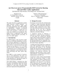
Figure 14. <strong>ADT7467</strong> Implementation<br />
http://onsemi.com<br />
9<br />
Recommended Implementation<br />
Configuring the <strong>ADT7467</strong> as in Figure NO TAG allows<br />
the system designer to use the following features:<br />
� Two PWM Outputs for <strong>Fan</strong> Control of Up to Three<br />
<strong>Fan</strong>s (The Front <strong>and</strong> Rear Chassis <strong>Fan</strong>s are Connected in<br />
Parallel)<br />
� Three TACH <strong>Fan</strong> Speed Measurement Inputs<br />
� VCC Measured Internally through Pin 3<br />
� CPU Temperature Measured Using the <strong>Remote</strong> 1<br />
Temperature Channel<br />
� Ambient Temperature Measured through the <strong>Remote</strong> 2<br />
Temperature Channel<br />
� Bidirectional THERM Pin. This Feature Allows Intel �<br />
Pentium � 4 PROCHOT <strong>Monitor</strong>ing <strong>and</strong> Can Function as<br />
an Overtemperature THERM Output. Alternatively, it<br />
Can be Programmed as an SMBALERT System Interrupt<br />
Output<br />
D2+<br />
D2−<br />
THERM<br />
SDA<br />
SCL<br />
SMBALERT<br />
GND<br />
PROCHOT<br />
CPU FAN<br />
ICH<br />
CPU<br />
write operation is only limited by what the master <strong>and</strong> slave<br />
devices can h<strong>and</strong>le.<br />
When all data bytes have been read or written, stop<br />
conditions are established. In write mode, the master pulls<br />
the data line high during the 10th clock pulse to assert a stop<br />
condition. In read mode, the master device overrides the<br />
acknowledge bit by pulling the data line high during the low<br />
period before the ninth clock pulse. This is known as a no<br />
acknowledge. The master then takes the data line low during<br />
the low period before the 10th clock pulse, <strong>and</strong> then high<br />
during the 10th clock pulse to assert a stop condition.<br />
Any number of bytes of data can be transferred over the<br />
serial bus in one operation. It is not possible to mix a read <strong>and</strong><br />
a write in one operation, however, because the type of<br />
operation is determined at the beginning <strong>and</strong> cannot<br />
subsequently be changed without starting a new operation.
In the <strong>ADT7467</strong>, write operations contain either one or<br />
two bytes, <strong>and</strong> read operations contain one byte. To write<br />
data to a device data register or read data from it, the address<br />
pointer register must first be set. The first byte of a write<br />
operation always contains an address, which is stored in the<br />
address pointer register, <strong>and</strong> the second byte, if there is a<br />
second byte, is written to the register selected by the address<br />
pointer register.<br />
This write operation is illustrated in Figure 15. The device<br />
address is sent over the bus, <strong>and</strong> then R/W is set to 0. This<br />
is followed by two data bytes. The first data byte is the<br />
address of the internal data register, <strong>and</strong> the second data byte<br />
is the data written to that internal data register.<br />
When reading data from a register, there are two<br />
possibilities:<br />
1. If the address pointer register value of the<br />
<strong>ADT7467</strong> is unknown or not the desired value, it<br />
must be set to the correct value before data can be<br />
read from the desired data register. This is<br />
achieved by writing a data byte containing the<br />
register address to the <strong>ADT7467</strong>. This is shown in<br />
Figure 16. A read operation is then performed<br />
SCL<br />
<strong>ADT7467</strong><br />
http://onsemi.com<br />
10<br />
consisting of the serial bus address <strong>and</strong> the R/W<br />
bit set to 1, followed by the data byte read from<br />
the data register. This is shown in Figure 17.<br />
2. If the address pointer register is known to be at the<br />
desired address, data can be read from the<br />
corresponding data register without first writing to<br />
the address pointer register, as shown in Figure 17.<br />
If the address pointer register is already at the correct<br />
value, it is possible to read a data byte from the data register<br />
without first writing to the address pointer register.<br />
However, it is not possible to write data to a register without<br />
writing to the address pointer register, because the first data<br />
byte of a write is always written to the address pointer<br />
register.<br />
In addition to supporting the send byte <strong>and</strong> receive byte<br />
protocols, the <strong>ADT7467</strong> also supports the read byte<br />
protocol. (See the Intel System Management Bus<br />
Specifications Rev. 2 for more information.)<br />
If several read or write operations must be performed in<br />
succession, the master can send a repeat start condition<br />
instead of a stop condition to begin a new operation.<br />
SDA 0 1 0 1 1 1 0 R/W D7 D6 D5 D4 D3 D2 D1 D0<br />
START BY<br />
MASTER<br />
1 9 1<br />
FRAME 1<br />
SERIAL BUS ADDRESS BYTE<br />
SCL (CONTINUED)<br />
SDA (CONTINUED)<br />
ACK. BY<br />
<strong>ADT7467</strong><br />
ACK. BY<br />
<strong>ADT7467</strong><br />
FRAME 2<br />
ADDRESS POINTER REGISTER BYTE<br />
1 9<br />
D7 D6 D5 D4 D3 D2 D1 D0<br />
FRAME 3<br />
DATA BYTE<br />
ACK. BY<br />
<strong>ADT7467</strong><br />
Figure 15. Writing a Register Address to the Address Pointer Register, then Writing Data to the Selected Register<br />
SCL<br />
1 9 1<br />
SDA 0 1 0 1 1 1 0 R/W D7 D6 D5 D4 D3 D2 D1 D0<br />
START BY<br />
MASTER FRAME 1<br />
SERIAL BUS ADDRESS BYTE<br />
ACK. BY<br />
<strong>ADT7467</strong><br />
ACK. BY<br />
FRAME 2<br />
<strong>ADT7467</strong><br />
ADDRESS POINTER REGISTER BYTE<br />
SCL<br />
Figure 16. Writing to the Address Pointer Register Only<br />
1 9 1<br />
SDA 0 1 0 1 1 1 0<br />
R/W<br />
D7 D6 D5 D4 D3 D2 D1 D0<br />
START BY<br />
MASTER FRAME 1<br />
SERIAL BUS ADDRESS BYTE<br />
ACK. BY<br />
<strong>ADT7467</strong><br />
FRAME 2<br />
DATA BYTE FROM <strong>ADT7467</strong><br />
NO ACK. BY<br />
MASTER<br />
Figure 17. Reading Data from a Previously Selected Register<br />
9<br />
9<br />
9<br />
STOP BY<br />
MASTER<br />
STOP BY<br />
MASTER<br />
STOP BY<br />
MASTER
Write Operations<br />
The SMBus specification defines several protocols for<br />
different types of read <strong>and</strong> write operations. The ones used<br />
in the <strong>ADT7467</strong> are discussed here. The following<br />
abbreviations are used in Figure 18 through Figure 20:<br />
S = start<br />
P = stop<br />
R = read<br />
W = write<br />
A = acknowledge<br />
A = no acknowledge<br />
The <strong>ADT7467</strong> uses the following SMBus write protocols.<br />
Send Byte<br />
In this operation, the master device sends a single<br />
comm<strong>and</strong> byte to a slave device as follows:<br />
1. The master device asserts a start condition on<br />
SDA.<br />
2. The master sends the 7-bit slave address followed<br />
by the write bit (low).<br />
3. The addressed slave device asserts an<br />
acknowledge on SDA.<br />
4. The master sends a comm<strong>and</strong> code.<br />
5. The slave asserts an acknowledge on SDA.<br />
6. The master asserts a stop condition on SDA, <strong>and</strong><br />
the transaction ends.<br />
For the <strong>ADT7467</strong>, the send byte protocol is used to write<br />
a register address to RAM for a subsequent single byte read<br />
from the same address. This operation is illustrated in<br />
Figure 18.<br />
1 2 3 4 5 6<br />
S<br />
Slave<br />
A<br />
Register<br />
A P<br />
Address<br />
W<br />
Address<br />
Figure 18. Setting a Register Address for<br />
Subsequent Read<br />
If the master is required to read data from the register<br />
directly after setting up the address, it can assert a repeat start<br />
condition immediately after the final acknowledge <strong>and</strong> carry<br />
out a single byte read without asserting an intermediate stop<br />
condition.<br />
Write Byte<br />
In this operation, the master device sends a comm<strong>and</strong> byte<br />
<strong>and</strong> one data byte to the slave device as follows:<br />
1. The master device asserts a start condition on<br />
SDA.<br />
2. The master sends the 7-bit slave address followed<br />
by the write bit (low).<br />
3. The addressed slave device asserts an<br />
acknowledge on SDA.<br />
4. The master sends a comm<strong>and</strong> code.<br />
5. The slave asserts an acknowledge on SDA.<br />
6. The master sends a data byte.<br />
7. The slave asserts an acknowledge on SDA.<br />
<strong>ADT7467</strong><br />
http://onsemi.com<br />
11<br />
8. The master asserts a stop condition on SDA to end<br />
the transaction.<br />
This operation is illustrated in Figure 19.<br />
1 2 3 4 5 6 7 8<br />
S<br />
Slave<br />
W A<br />
Slave<br />
A Data A P<br />
Address Address<br />
Figure 19. Single Byte Write to a Register<br />
Read Operations<br />
The <strong>ADT7467</strong> uses the following SMBus read protocols.<br />
Receive Byte<br />
This operation is useful when repeatedly reading a single<br />
register. The register address must have been set up<br />
previously. In this operation, the master device receives a<br />
single byte from a slave device as follows:<br />
1. The master device asserts a start condition on<br />
SDA.<br />
2. The master sends the 7-bit slave address followed<br />
by the read bit (high).<br />
3. The addressed slave device asserts an<br />
acknowledge on SDA.<br />
4. The master receives a data byte.<br />
5. The master asserts a no acknowledge on SDA.<br />
6. The master asserts a stop condition on SDA, <strong>and</strong><br />
the transaction ends.<br />
In the <strong>ADT7467</strong>, the receive byte protocol is used to read<br />
a single byte of data from a register whose address has<br />
previously been set by a send byte or write byte operation.<br />
This operation is illustrated in Figure 20.<br />
1 2 3 4 5 6<br />
S Slave R A Data A P<br />
Address<br />
Figure 20. Single Byte Read from a Register<br />
Alert Response Address<br />
Alert response address (ARA) is a feature of SMBus<br />
devices that allows an interrupting device to identify itself<br />
to the host when multiple devices exist on the same bus.<br />
The SMBALERT output can be used as either an interrupt<br />
output or an SMBALERT. One or more outputs can be<br />
connected to a common SMBALERT line connected to the<br />
master. If a device’s SMBALERT line goes low, the<br />
following procedure occurs:<br />
1. SMBALERT is pulled low.<br />
2. The master initiates a read operation <strong>and</strong> sends the<br />
alert response address (ARA = 0001 100). This is<br />
a general call address that must not be used as a<br />
specific device address.<br />
3. The device whose SMBALERT output is low<br />
responds to the alert response address, <strong>and</strong> the<br />
master reads its device address. The address of the
device is now known <strong>and</strong> can be interrogated in<br />
the usual way.<br />
4. If more than one device’s SMBALERT output is<br />
low, the one with the lowest device address has<br />
priority in accordance with normal SMBus<br />
arbitration.<br />
5. Once the <strong>ADT7467</strong> has responded to the alert<br />
response address, the master must read the status<br />
registers. The SMBALERT is cleared only if the<br />
error condition is absent.<br />
SMBus Timeout<br />
The <strong>ADT7467</strong> includes an SMBus timeout feature. If<br />
there is no SMBus activity for 35 ms, the <strong>ADT7467</strong> assumes<br />
that the bus is locked <strong>and</strong> releases the bus. This prevents the<br />
device from locking or holding the SMBus in anticipation of<br />
receiving data. Some SMBus controllers cannot h<strong>and</strong>le the<br />
SMBus timeout feature, so it can be disabled.<br />
Configuration Register 1 (0x40)<br />
TODIS = 0, SMBus timeout enabled (default)<br />
TODIS = 1, SMBus timeout disabled<br />
Analog-to-Digital Converter<br />
All analog inputs are multiplexed into the on-chip,<br />
successive approximation, analog-to-digital converter,<br />
which has a resolution of 10 bits. The basic input range is<br />
0 V to 2.25 V, but the input has built-in attenuators to allow<br />
measurement of VCCP without any external components. To<br />
allow for the tolerance of the supply voltage, the ADC<br />
produces an output of 3/4 full scale (decimal 768 or 300<br />
hexadecimal) for the nominal input voltage <strong>and</strong>, therefore,<br />
has adequate headroom to deal with overvoltages.<br />
Voltage Measurement Input<br />
The <strong>ADT7467</strong> has one external voltage measurement<br />
channel. It can also measure its own supply voltage, VCC.<br />
Pin 14 can measure VCCP. The VCC supply voltage<br />
measurement is carried out through the VCC pin (Pin 3).<br />
Setting Bit 7 of Configuration Register 1 (0x40) allows a<br />
5 V supply to power the <strong>ADT7467</strong> <strong>and</strong> be measured without<br />
overranging the VCC measurement channel. The VCCP input<br />
can be used to monitor a chipset supply voltage in computer<br />
systems.<br />
Input Circuitry<br />
The internal structure for the VCCP analog input is shown<br />
in Figure 21. The input circuit consists of an input protection<br />
diode, an attenuator, <strong>and</strong> a capacitor to form a first-order<br />
low-pass filter that gives the input immunity to high<br />
frequency noise.<br />
V CCP<br />
17.5 k�<br />
52.5 k�<br />
35 pF<br />
Figure 21. Structure of Analog Inputs<br />
<strong>ADT7467</strong><br />
http://onsemi.com<br />
12<br />
Voltage Measurement Registers<br />
Register 0x21 VCCP reading = 0x00 default<br />
Register 0x22 VCC reading = 0x00 default<br />
V CCP Limit Registers<br />
Associated with the VCCP <strong>and</strong> VCC measurement<br />
channels is a high <strong>and</strong> low limit register. Exceeding the<br />
programmed high or low limit causes the appropriate status<br />
bit to be set. Exceeding either limit can also generate<br />
SMBALERT interrupts.<br />
Register 0x46 VCCP low limit = 0x00 default<br />
Register 0x47 VCCP high limit = 0xFF default<br />
Register 0x48 VCC low limit = 0x00 default<br />
Register 0x49 VCC high limit = 0xFF default<br />
Table 6 shows the input ranges of the analog inputs <strong>and</strong><br />
output codes of the 10-bit ADC.<br />
When the ADC is running, it samples <strong>and</strong> converts a<br />
voltage input in 0.7 ms <strong>and</strong> averages 16 conversions to<br />
reduce noise; a measurement takes nominally 11 ms.<br />
Additional ADC Functions for Voltage Measurements<br />
A number of other functions are available on the<br />
<strong>ADT7467</strong> to offer the system designer increased flexibility.<br />
Turn-off Averaging<br />
For each voltage measurement read from a value register,<br />
16 readings are made internally, the results of which are<br />
averaged <strong>and</strong> then placed into the value register. For<br />
instances where faster conversions are needed, setting Bit 4<br />
of Configuration Register 2 (0x73) turns averaging off. This<br />
produces a reading that is 16 times faster (0.7 ms), but the<br />
reading may be noisier.<br />
Bypass Voltage Input Attenuator<br />
Setting Bit 5 of Configuration Register 2 (0x73) removes<br />
the attenuation circuitry from the VCCP input. This allows<br />
the user to directly connect external sensors or to rescale the<br />
analog voltage measurement inputs for other applications.<br />
The input range of the ADC without the attenuators is 0 V<br />
to 2.25 V.<br />
Single-channel ADC Conversion<br />
Setting Bit 6 of Configuration Register 2 (0x73) places the<br />
<strong>ADT7467</strong> into single−channel ADC conversion mode. In<br />
this mode, the <strong>ADT7467</strong> can be made to read a single<br />
voltage channel only. If the internal <strong>ADT7467</strong> clock is used,<br />
the selected input is read every 0.7 ms. The appropriate ADC<br />
channel is selected by writing to Bits of the TACH1<br />
minimum high byte register (0x55).
Table 5. PROGRAMMING SINGLE-CHANNEL<br />
ADC MODE<br />
Bits , Register 0x55 Channel Selected<br />
001 V CCP<br />
010 VCC 101 <strong>Remote</strong> 1 Temperature<br />
110 Local Temperature<br />
111 <strong>Remote</strong> 2 Temperature<br />
<strong>ADT7467</strong><br />
http://onsemi.com<br />
13<br />
Configuration Register 2 (0x73)<br />
= 1, Averaging Off<br />
= 1, Bypass Input Attenuators<br />
= 1, Single-channel Conversion Mode<br />
TACH1 Minimum High Byte (0x55)<br />
Selects ADC Channel for Single-channel Convert<br />
Mode<br />
Table 6. 10-BIT ANALOG-TO-DIGITAL OUTPUT CODE VS. VIN Input Voltage A/D Output<br />
V CC (5 V IN) V CC (3.3 V IN) V CCP Decimal Binary (10 Bits)<br />
2.9970 1023 11111111 11<br />
�<br />
�<br />
�<br />
�
Temperature Measurement<br />
A simple method of measuring temperature is to exploit<br />
the negative temperature coefficient of a diode, measuring<br />
the base-emitter voltage (VBE) of a transistor operated at<br />
constant current. Unfortunately, this technique requires<br />
calibration to null the effect of the absolute value of VBE,<br />
which varies from each device.<br />
The technique used in the <strong>ADT7467</strong> is to measure the<br />
change in VBE when the device is operated at three currents.<br />
Previous devices have used only two operating currents, but<br />
the use of a third current allows automatic cancellation of<br />
resistances in series with the external temperature sensor.<br />
Figure 23 shows the input signal conditioning used to<br />
measure the output of an external temperature sensor. This<br />
figure shows the external sensor as a substrate transistor, but<br />
it could equally be a discrete transistor. If a discrete<br />
transistor is used, the collector is not grounded <strong>and</strong> should<br />
be linked to the base. To prevent ground noise from<br />
interfering with the measurement, the more negative<br />
terminal of the sensor is not referenced to ground but is<br />
biased above ground by an internal diode at the D− input. C1<br />
can optionally be added as a noise filter (the recommended<br />
maximum value is 1,000 pF). However, a better option in<br />
noisy environments is to add a filter as described in the Noise<br />
Filtering section.<br />
Local Temperature Measurement<br />
The <strong>ADT7467</strong> contains an on-chip b<strong>and</strong> gap temperature<br />
sensor whose output is digitized by the on-chip 10-bit ADC.<br />
The 8-bit MSB temperature data is stored in the local<br />
temperature register (Address 0x26). Because both positive<br />
<strong>and</strong> negative temperatures can be measured, the temperature<br />
data is stored in Offset 64 format or twos complement<br />
format, as shown in Table 7 <strong>and</strong> Table 8. Theoretically, the<br />
REMOTE<br />
SENSING<br />
TRANSISTOR<br />
D+<br />
D−<br />
I N2 � I<br />
N1 � I<br />
<strong>ADT7467</strong><br />
I BIAS<br />
http://onsemi.com<br />
14<br />
temperature sensor <strong>and</strong> ADC can measure temperatures<br />
from −128�C to +127�C (or −64�C to +191�C in the<br />
extended temperature range) with a resolution of 0.25�C.<br />
However, this exceeds the operating temperature range of<br />
the device, preventing local temperature measurements<br />
outside the <strong>ADT7467</strong> operating temperature range.<br />
<strong>Remote</strong> Temperature Measurement<br />
The <strong>ADT7467</strong> can measure the temperature of two remote<br />
diode sensors or diode-connected transistors connected to<br />
Pin 10 <strong>and</strong> Pin 11 or to Pin 12 <strong>and</strong> Pin 13.<br />
The forward voltage of a diode or diode-connected<br />
transistor operated at a constant current exhibits a negative<br />
temperature coefficient of about −2 mV/�C. Unfortunately,<br />
the absolute value of VBE varies from each device <strong>and</strong> thus<br />
requires individual calibration; therefore, the technique is<br />
unsuitable for mass production. The technique used in the<br />
<strong>ADT7467</strong> is to measure the change in VBE when the device<br />
is operated at three currents. This is given by:<br />
�V BE � kT�q � ln(N)<br />
where:<br />
k is Boltzmann’s constant.<br />
q is the charge on the carrier.<br />
T is the absolute temperature in Kelvins.<br />
N is the ratio of the two currents.<br />
(eq. 1)<br />
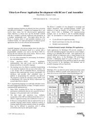
Figure 22 shows the input signal conditioning used to<br />
measure the output of a remote temperature sensor. This<br />
figure shows the external sensor as a substrate transistor<br />
provided for temperature monitoring on some<br />
microprocessors. It could also be a discrete transistor such<br />
as a 2N3904/2N3906.<br />
LOW-PASS FILTER<br />
f C = 65 kHz<br />
Figure 22. Signal Conditioning for <strong>Remote</strong> Diode Temperature Sensors<br />
If a discrete transistor is used, the collector is not grounded<br />
<strong>and</strong> should be linked to the base. If a PNP transistor is used,<br />
the base is connected to the D− input <strong>and</strong> the emitter is<br />
connected to the D+ input. If an NPN transistor is used, the<br />
emitter is connected to the D− input <strong>and</strong> the base is<br />
connected to the D+ input. Figure 24 <strong>and</strong> Figure 25 show<br />
how to connect the <strong>ADT7467</strong> to an NPN or PNP transistor<br />
for temperature measurement. To prevent ground noise from<br />
V DD<br />
V OUT+<br />
To ADC<br />
V OUT−<br />
interfering with the measurement, the more negative<br />
terminal of the sensor is not referenced to ground but is<br />
biased above ground by an internal diode at the D− input.<br />
To measure �VBE, the operating current through the<br />
sensor is switched among three related currents. Shown in<br />
Figure 22, N1 � I <strong>and</strong> N2 � I are different multiples of the<br />
current I. The currents through the temperature diode are<br />
switched between I <strong>and</strong> N1 � I, resulting in �VBE1; then
they are switched between I <strong>and</strong> N2 � I, resulting in �VBE2.<br />
The temperature can then be calculated using the two �VBE<br />
measurements. This method can also cancel the effect of<br />
series resistance on the temperature measurement.<br />
The resulting �VBE waveforms are passed through a<br />
65 kHz low-pass filter to remove noise <strong>and</strong> then sent to a<br />
chopper-stabilized amplifier that amplifies <strong>and</strong> rectifies the<br />
waveform to produce a dc voltage proportional to �VBE.<br />
The ADC digitizes this voltage, <strong>and</strong> a temperature<br />
measurement is produced. To reduce the effects of noise,<br />
digital filtering is performed by averaging the results of 16<br />
measurement cycles.<br />
The results of remote temperature measurements are<br />
stored in 10-bit twos complement format, as listed in<br />
Table 7. The extra resolution for the temperature<br />
measurements is held in the Extended Resolution Register 2<br />
(0x77). This produces temperature readings with a<br />
resolution of 0.25�C.<br />
Series Resistance Cancellation<br />
Parasitic resistance to the <strong>ADT7467</strong> D+ <strong>and</strong> D− inputs<br />
(seen in series with the remote diode) is caused by a variety<br />
of factors, including PCB track resistance <strong>and</strong> track length.<br />
This series resistance appears as a temperature offset in the<br />
remote sensor’s temperature measurement. This error<br />
typically causes a 0.5�C offset per 1�� of parasitic resistance<br />
in series with the remote diode.<br />
The <strong>ADT7467</strong> automatically cancels the effect of this<br />
series resistance on the temperature reading, providing a<br />
more accurate result without the need for user<br />
characterization of this resistance. The <strong>ADT7467</strong> is<br />
designed to automatically cancel, typically up to 3�k� of<br />
resistance. By using an advanced temperature measurement<br />
method, this is transparent to the user. This feature allows<br />
resistances to be added to the sensor path to produce a filter,<br />
allowing the part to be used in noisy environments. See the<br />
Noise Filtering section for details.<br />
Noise Filtering<br />
For temperature sensors operating in noisy environments,<br />
previous practice involved placing a capacitor across the D+<br />
<strong>and</strong> D− pins to help combat the effects of noise. However,<br />
large capacitances affect the accuracy of the temperature<br />
measurement, leading to a recommended maximum<br />
capacitor value of 1,000 pF. A capacitor of this value<br />
reduces the noise but does not eliminate it, making use of the<br />
sensor difficult in a very noisy environment.<br />
The <strong>ADT7467</strong> has a major advantage over other devices<br />
for eliminating the effects of noise on the external sensor.<br />
Using the series resistance cancellation feature, a filter can<br />
be constructed between the external temperature sensor <strong>and</strong><br />
the device. The effect of filter resistance seen in series with<br />
the remote sensor is automatically canceled from the<br />
temperature result.<br />
The construction of a filter allows the <strong>ADT7467</strong> <strong>and</strong> the<br />
remote temperature sensor to operate in noisy environments.<br />
<strong>ADT7467</strong><br />
http://onsemi.com<br />
15<br />
Figure 23 shows a low-pass R-C-R filter with the following<br />
values:<br />
R�=�100��, C�=�1�nF<br />
This filtering reduces both common-mode noise <strong>and</strong><br />
differential noise.<br />
REMOTE<br />
TEMPERATURE<br />
SENSOR<br />
100 �<br />
100 �<br />
1 nF<br />
Figure 23. Filter Between <strong>Remote</strong> Sensor <strong>and</strong><br />
<strong>ADT7467</strong><br />
Factors Affecting Diode Accuracy<br />
<strong>Remote</strong> Sensing Diode<br />
The <strong>ADT7467</strong> is designed to work with either substrate<br />
transistors built into processors or discrete transistors.<br />
Substrate transistors are generally PNP types with the<br />
collector connected to the substrate. Discrete types can be<br />
either PNP or NPN transistors connected as a diode<br />
(base-shorted to the collector). If an NPN transistor is used,<br />
the collector <strong>and</strong> base are connected to D+ <strong>and</strong> the emitter<br />
is connected to D−. If a PNP transistor is used, the collector<br />
<strong>and</strong> base are connected to D− <strong>and</strong> the emitter is connected to<br />
D+.<br />
To reduce the error due to variations in both substrate <strong>and</strong><br />
discrete transistors, a number of factors should be taken into<br />
consideration:<br />
� The ideality factor, nf, of the transistor is a measure of<br />
the deviation of the thermal diode from ideal behavior.<br />
The <strong>ADT7467</strong> is trimmed for an nf value of 1.008. Use<br />
the following equation to calculate the error introduced<br />
at a temperature, T (�C), when using a transistor whose<br />
nf does not equal 1.008. See the processor’s data sheet<br />
for the nf values.<br />
�T = (nf − 1.008)/1.008 � (273.15 K + T)<br />
� To correct for this error, the user can write the �T value<br />
to the offset register, <strong>and</strong> the <strong>ADT7467</strong> automatically<br />
adds it to or subtracts it from the temperature<br />
measurement.<br />
� Some CPU manufacturers specify the high <strong>and</strong> low<br />
current levels of the substrate transistors. The high<br />
current level of the <strong>ADT7467</strong>, IHIGH, is 96 �A, <strong>and</strong> the<br />
low level current, ILOW, is 6 �A. If the <strong>ADT7467</strong><br />
current levels do not match the current levels specified<br />
by the CPU manufacturer, it may be necessary to<br />
remove an offset. The CPU’s data sheet should provide<br />
information relating to nf to compensate for differences.<br />
An offset can be programmed to the offset register. It is<br />
important to note that if more than one offset must be<br />
considered, the algebraic sum of these offsets must be<br />
programmed to the offset register.<br />
D+<br />
D−
If a discrete transistor is used with the <strong>ADT7467</strong>, the best<br />
accuracy is obtained by choosing devices according to the<br />
following criteria:<br />
� Base-emitter voltage is greater than 0.25 V at 6 �A with<br />
the highest operating temperature.<br />
� Base-emitter voltage is less than 0.95 V at 100 �A with<br />
the lowest operating temperature.<br />
� Base resistance is less than 100 �.<br />
� There is a small variation in hFE (for example, 50 to<br />
150) that indicates tight control of VBE characteristics.<br />
Transistors such as 2N3904, 2N3906, or equivalents in<br />
SOT−23 packages are suitable devices to use.<br />
Table 7. TWOS COMPLEMENT TEMPERATURE DATA<br />
FORMAT<br />
Temperature Digital Output (10-bit) (Note 1)<br />
−128�C 1000 0000 00<br />
−125�C 1000 0011 00<br />
−100�C 1001 1100 00<br />
−75�C 1011 0101 00<br />
−50�C 1100 1110 00<br />
−25�C 1110 0111 00<br />
−10�C 1111 0110 00<br />
0�C 0000 0000 00<br />
+10.25�C 0000 1010 01<br />
+25.5�C 0001 1001 10<br />
+50.75�C 0011 0010 11<br />
+75�C 0100 1011 00<br />
+100�C 0110 0100 00<br />
+125�C 0111 1101 00<br />
+127�C 0111 1111 00<br />
1. Bold numbers denote 2 LSBs of measurement in Extended<br />
Resolution Register 2 (0x77) with 0.25�C resolution.<br />
Table 8. OFFSET 64 TEMPERATURE DATA FORMAT<br />
Temperature Digital Output (10-bit) (Note 1)<br />
−64�C 0000 0000 00<br />
−1�C 0011 1111 00<br />
0�C 0100 0000 00<br />
+1�C 0100 0001 00<br />
+10�C 0100 1010 00<br />
+25�C 0101 1001 00<br />
+50�C 0111 0010 00<br />
+75�C 1000 1001 00<br />
+100�C 1010 0100 00<br />
+125�C 1011 1101 00<br />
+191�C 1111 1111 00<br />
1. Bold numbers denote 2 LSBs of measurement in Extended<br />
Resolution Register 2 (0x77) with 0.25�C resolution.<br />
<strong>ADT7467</strong><br />
http://onsemi.com<br />
16<br />
2N3904<br />
NPN<br />
<strong>ADT7467</strong><br />
D+<br />
Figure 24. Measuring Temperature by Using an NPN<br />
Transistor<br />
2N3906<br />
PNP<br />
Figure 25. Measuring Temperature by Using a PNP<br />
Transistor<br />
D−<br />
<strong>ADT7467</strong><br />
D+<br />
Nulling Temperature Errors<br />
As CPUs run faster, it is more difficult to avoid high<br />
frequency clocks when routing the D+/D− traces around a<br />
system board. Even when recommended layout guidelines<br />
are followed, some temperature errors may still be attributed<br />
to noise coupled onto the D+/D− lines. Constant high<br />
frequency noise usually attenuates or increases temperature<br />
measurements by a linear, constant value.<br />
The <strong>ADT7467</strong> has temperature offset registers at Address<br />
0x70 <strong>and</strong> Address 0x72 for the <strong>Remote</strong> 1 <strong>and</strong> <strong>Remote</strong> 2<br />
temperature channels, respectively. By performing a<br />
one-time calibration of the system, the user can determine<br />
the offset caused by system board noise <strong>and</strong> null it using the<br />
offset registers. The offset registers automatically add an<br />
Offset 64/twos complement 8-bit reading to every<br />
temperature measurement. The LSBs add 0.5�C offset to the<br />
temperature reading; therefore, the 8-bit register effectively<br />
allows temperature offsets of up to �64�C with a resolution<br />
of 0.5�C. This ensures that the readings in the temperature<br />
measurement registers are as accurate as possible.<br />
Temperature Offset Registers<br />
Register 0x70 <strong>Remote</strong> 1 Temperature Iffset = 0x00<br />
(0�C Default)<br />
Register 0x71 Local Temperature Offset = 0x00<br />
(0�C Default)<br />
Register 0x72 <strong>Remote</strong> 2 Temperature Offset = 0x00<br />
(0�C Default)<br />
ADT7460/<strong>ADT7467</strong> Backwards-compatible Mode<br />
By setting Bit 1 of Configuration Register 5 (0x7C), all<br />
temperature measurements are stored in the zone<br />
temperature value registers (Register 0x25, Register 0x26,<br />
<strong>and</strong> Register 0x27) in twos complement format in the range<br />
−128�C to +127�C. (The ADT7468 makes calculations<br />
based on the Offset 64 extended range <strong>and</strong> clamps the results<br />
if necessary.) The temperature limits must be reprogrammed<br />
in twos complement format. If a twos complement<br />
D−
temperature below −63�C is entered, the temperature is<br />
clamped to −63�C. In this mode, the diode fault condition<br />
remains −128�C = 1000 0000, whereas the fault condition is<br />
represented by −64�C = 0000 0000 in the extended<br />
temperature range (−64�C to +191�C).<br />
Table 9. TEMPERATURE MEASUREMENT<br />
REGISTERS<br />
Register Description Default<br />
0x25 <strong>Remote</strong> 1 Temperature 0x01<br />
0x26 Local Temperature 0x01<br />
0x27 <strong>Remote</strong> 2 Temperature 0x01<br />
0x77 Extended Resolution 2 0x00<br />
Table 10. EXTENDED RESOLUTION TEMPERATURE<br />
MEASUREMENT REGISTER BITS<br />
Bit Mnemonic Description<br />
TDM2 <strong>Remote</strong> 2 Temperature LSBs<br />
LTMP Local Temperature LSBs<br />
TDM1 <strong>Remote</strong> 1 Temperature LSBs<br />
Temperature Measurement Limit Registers<br />
High <strong>and</strong> low limit registers are associated with each<br />
temperature measurement channel. Exceeding the<br />
programmed high or low limit sets the appropriate status bit<br />
<strong>and</strong> can also generate SMBALERT interrupts.<br />
Table 11. TEMPERATURE MEASUREMENT LIMIT<br />
REGISTERS<br />
Register Description Default<br />
0x4E <strong>Remote</strong> 1 Temperature Low Limit 0x01<br />
0x4F <strong>Remote</strong> 1 Temperature High Limit 0x7F<br />
0x50 Local Temperature Low Limit 0x01<br />
0x51 Local Temperature High Limit 0x7F<br />
0x52 <strong>Remote</strong> 2 Temperature Low Limit 0x01<br />
0x53 <strong>Remote</strong> 2 Temperature High Limit 0x7F<br />
Reading Temperature from the <strong>ADT7467</strong><br />
It is important to note that temperature can be read from<br />
the <strong>ADT7467</strong> as an 8-bit value (with 1�C resolution) or as<br />
a 10-bit value (with 0.25�C resolution). If only 1�C<br />
resolution is required, the temperature readings can be read at<br />
any time <strong>and</strong> in no particular order.<br />
If the 10-bit measurement is required, this involves a<br />
2-register read for each measurement. The extended<br />
resolution register (0x77) should be read first. Then all<br />
temperature reading registers freeze until all temperature<br />
reading registers are read. This prevents updating of an MSB<br />
reading while its two LSBs are read <strong>and</strong> vice versa.<br />
<strong>ADT7467</strong><br />
http://onsemi.com<br />
17<br />
Additional ADC Functions for Temperature<br />
Measurement<br />
A number of other functions are available on the<br />
<strong>ADT7467</strong> to offer the system designer increased flexibility.<br />
Turn-off Averaging<br />
For each temperature measurement read from a value<br />
register, 16 readings are made internally, the results of which<br />
are averaged <strong>and</strong> then placed into the value register.<br />
Sometimes it is necessary to perform a very fast<br />
measurement. Setting Bit 4 of Configuration Register 2<br />
(0x73) turns averaging off.<br />
Table 12. CONVERSION TIME WITH AVERAGING<br />
DISABLED<br />
Channel Measurement Time<br />
Voltage Channels 0.7 ms<br />
<strong>Remote</strong> Temperature 1 7 ms<br />
<strong>Remote</strong> Temperature 2 7 ms<br />
Local Temperature 1.3 ms<br />
Table 13. CONVERSION TIME WITH AVERAGING<br />
ENABLED<br />
Channel Measurement Time<br />
Voltage Channels 11 ms<br />
<strong>Remote</strong> Temperature 39 ms<br />
Local Temperature 12 ms<br />
Single-channel ADC Conversions<br />
Setting Bit 6 of Configuration Register 2 (0x73) places<br />
the <strong>ADT7467</strong> into single-channel ADC conversion mode. In<br />
this mode, users can read a single temperature channel only.<br />
The appropriate ADC channel is selected by writing to<br />
Bits of the TACH1 minimum high byte register<br />
(0x55).<br />
Table 14. CHANNEL SELECTION<br />
Bits , Register 0x55 Channel Selected<br />
101 <strong>Remote</strong> 1 Temperature<br />
110 Local Temperature<br />
111 <strong>Remote</strong> 2 Temperature<br />
Configuration Register 2 (0x73)<br />
= 1, Averaging Off<br />
= 1, Single-channel Convert Mode<br />
TACH1 Minimum High Byte (0x55)<br />
Selects ADC Channel for Single-channel Convert<br />
Mode
Overtemperature Events<br />
Overtemperature events on a temperature channel can be<br />
automatically detected <strong>and</strong> dealt with in automatic fan speed<br />
control mode. Register 0x6A to Register 0x6C contain the<br />
THERM temperature limits. When a temperature exceeds<br />
its THERM temperature limit, all PWM outputs run at the<br />
maximum PWM duty cycle (0x38, 0x39, 0x3A); therefore,<br />
fans run at the fastest speed allowed <strong>and</strong> continue running at<br />
this speed until the temperature drops below THERM minus<br />
hysteresis. (This can be disabled by setting the BOOST bit<br />
in Configuration Register 3, Bit 2, Register 0x78.) The<br />
hysteresis value for that THERM temperature limit is the<br />
value programmed into Register 0x6D <strong>and</strong> Register 0x6E<br />
(hysteresis registers). The default hysteresis value is 4�C.<br />
THERM LIMIT<br />
TEMPERATURE<br />
FANS<br />
100%<br />
HYSTERESIS<br />
(�C)<br />
Figure 26. THERM Temperature Limit Operation<br />
Limits, Status Registers, <strong>and</strong> Interrupts<br />
Limit Values<br />
High <strong>and</strong> low limits are associated with each<br />
measurement channel on the <strong>ADT7467</strong>. These limits form<br />
the basis of system-status monitoring in that a status bit can<br />
be set for any out-of-limit condition <strong>and</strong> detected by polling<br />
the device. Alternatively, SMBALERT interrupts can be<br />
generated to flag a processor or microcontroller of<br />
out-of-limit conditions.<br />
8-bit Limits<br />
The following is a list of 8-bit limits on the <strong>ADT7467</strong>.<br />
Table 15. VOLTAGE LIMIT REGISTERS<br />
Register Description Default<br />
0x46 VCCP Low Limit 0x00<br />
0x47 VCCP High Limit 0xFF<br />
0x48 VCC Low Limit 0x00<br />
0x49 VCC High Limit 0xFF<br />
Table 16. THERM TIMER LIMIT REGISTERS<br />
Register Description Default<br />
0x7A THERM Timer Limit 0x00<br />
<strong>ADT7467</strong><br />
http://onsemi.com<br />
18<br />
Table 17. TEMPERATURE LIMIT REGISTERS<br />
Register Description Default<br />
0x4E <strong>Remote</strong> 1 Temperature Low Limit 0x01<br />
0x4F <strong>Remote</strong> 1 Temperature High Limit 0x7F<br />
0x6A <strong>Remote</strong> 1 THERM Limit 0xA4<br />
0x50 Local Temperature Low Limit 0x01<br />
0x51 Local Temperature High Limit 0x7F<br />
0x6B Local THERM Limit 0xA4<br />
0x52 <strong>Remote</strong> 2 Temperature Low Limit 0x01<br />
0x53 <strong>Remote</strong> 2 Temperature High Limit 0x7F<br />
0x6C <strong>Remote</strong> 2 THERM Limit 0xA4<br />
16-bit Limits<br />
The fan TACH measurements are 16-bit results. The fan<br />
TACH limits are also 16 bits, consisting of a high byte <strong>and</strong><br />
low byte. Because slow or stalled fans are normally the only<br />
conditions of interest, only high limits exist for fan TACHs.<br />
Because the fan TACH period is measured, exceeding the<br />
limit indicates a slow or stalled fan.<br />
Table 18. FAN LIMIT REGISTERS<br />
Register Description Default<br />
0x54 TACH1 Minimum Low Byte 0xFF<br />
0x55 TACH1 Minimum High Byte 0xFF<br />
0x56 TACH2 Minimum Low Byte 0xFF<br />
0x57 TACH2 Minimum High Byte 0xFF<br />
0x58 TACH3 Minimum Low Byte 0xFF<br />
0x59 TACH3 Minimum High Byte 0xFF<br />
0x5A TACH4 Minimum Low Byte 0xFF<br />
0x5B TACH4 Minimum High Byte 0xFF<br />
Out-of-Limit Comparisons<br />
Once all limits are programmed, the <strong>ADT7467</strong> can be<br />
enabled for monitoring. The <strong>ADT7467</strong> measures all voltage<br />
<strong>and</strong> temperature measurements in round-robin format <strong>and</strong><br />
sets the appropriate status bit for out-of-limit conditions.<br />
TACH measurements are not part of this round-robin cycle.<br />
Comparisons are done differently, depending on whether the<br />
measured value is being compared to a high or low limit.<br />
High limit: > comparison performed<br />
Low limit: � comparison performed<br />
Voltage <strong>and</strong> temperature channels use a window<br />
comparator for error detecting <strong>and</strong>, therefore, have high <strong>and</strong><br />
low limits. <strong>Fan</strong> speed measurements use only a low limit.<br />
This fan limit is needed only in manual fan control mode.
Analog <strong>Monitor</strong>ing Cycle Time<br />
The analog monitoring cycle begins when a 1 is written to<br />
the start bit (Bit 0) of Configuration Register 1 (0x40). By<br />
default, the ADT7463 powers up with this bit set. The ADC<br />
measures each analog input in turn <strong>and</strong>, as each<br />
measurement is completed, the result is automatically stored<br />
in the appropriate value register. This round-robin<br />
monitoring cycle continues unless disabled by writing a 0 to<br />
Bit 0 of Configuration Register 1.<br />
As the ADC is normally left to free-run in this manner, the<br />
time to monitor all analog inputs is normally not of interest<br />
because the most recently measured value of an input can be<br />
read at any time.<br />
For applications where the monitoring cycle time is<br />
important, it can be calculated easily. The total number of<br />
channels measured is<br />
� One Dedicated Supply Voltage Input (VCCP)<br />
� One Supply Voltage (VCC Pin)<br />
� One Local Temperature<br />
� Two <strong>Remote</strong> Temperatures<br />
As mentioned previously, the ADC performs round-robin<br />
conversions. The total monitoring cycle time for averaged<br />
voltage <strong>and</strong> temperature monitoring is 145 ms. The total<br />
monitoring cycle time for voltage <strong>and</strong> temperature<br />
monitoring with averaging disabled is 19 ms. The <strong>ADT7467</strong><br />
is a derivative of the ADT7468. As a result, the total<br />
conversion time for the <strong>ADT7467</strong> <strong>and</strong> ADT7468 are the<br />
same, even though the <strong>ADT7467</strong> has less monitored<br />
channels.<br />
<strong>Fan</strong> TACH measurements are made in parallel <strong>and</strong> are not<br />
synchronized with the analog measurements in any way.<br />
Status Registers<br />
The results of limit comparisons are stored in Interrupt<br />
Status Register 1 <strong>and</strong> Interrupt Status Register 2. The status<br />
register bit for each channel reflects the status of the last<br />
measurement <strong>and</strong> limit comparison on that channel. If a<br />
measurement is within limits, the corresponding status<br />
register bit is cleared to 0. If the measurement is out of limit,<br />
the corresponding status register bit is set to 1.<br />
The state of the various measurement channels can be<br />
polled by reading the status registers over the serial bus. In<br />
Bit 7 (OOL) of Interrupt Status Register 1 (0x41), 1 means<br />
that an out-of-limit event has been flagged in Interrupt<br />
Status Register 2. This means that the user also should read<br />
Interrupt Status Register 2. Alternatively, Pin 5 or Pin 9 can<br />
be configured as an SMBALERT output. This hardware<br />
interrupt automatically notifies the system supervisor of an<br />
out-of-limit condition. Reading the status registers clears the<br />
appropriate status bit if the error condition that caused the<br />
interrupt is absent. Status register bits are sticky. Whenever<br />
<strong>ADT7467</strong><br />
http://onsemi.com<br />
19<br />
a status bit is set, indicating an out-of-limit condition, it<br />
remains set until read, even if the event that caused it is<br />
absent. The only way to clear the status bit is to read the<br />
status register after the event is absent. Interrupt mask<br />
registers (0x74 <strong>and</strong> 0x75) allow masking of individual<br />
interrupt sources to prevent an SMBALERT. However, if a<br />
masked interrupt source goes out of limit, its associated<br />
status bit is set in the interrupt status registers.<br />
Table 19. STATUS REGISTER 1 (REG. 0X41)<br />
Bit Mnemonic Description<br />
7 OOL 1 denotes a bit in Status Register 2 is set<br />
<strong>and</strong> Status Register 2 should be read.<br />
6 R2T 1 indicates that the <strong>Remote</strong> 2<br />
temperature high or low limit has been<br />
exceeded.<br />
5 LT 1 indicates that the Local temperature<br />
high or low limit has been exceeded.<br />
4 R1T 1 indicates that the <strong>Remote</strong> 1<br />
temperature high or low limit has been<br />
exceeded.<br />
2 V CC 1 indicates that the V CC high or low limit<br />
has been exceeded.<br />
1 V CCP 1 indicates that the V CCP high or low<br />
limit has been exceeded.<br />
Table 20. STATUS REGISTER 2 (REG. 0X42)<br />
Bit Mnemonic Description<br />
7 D2 1 indicates an open or short on<br />
D2+/D2− inputs.<br />
6 D1 1 indicates an open or short on<br />
D2+/D2− inputs.<br />
5 F4P 1 indicates that <strong>Fan</strong> 4 has dropped<br />
below minimum speed. Alternatively,<br />
indicates that THERM timer limit has<br />
been exceeded if the THERM timer<br />
function is used.<br />
4 FAN3 1 indicates that <strong>Fan</strong> 3 has dropped<br />
below minimum speed.<br />
3 FAN2 1 indicates that <strong>Fan</strong> 2 has dropped<br />
below minimum speed.<br />
2 FAN1 1 indicates that <strong>Fan</strong> 1 has dropped<br />
below minimum speed.<br />
1 OVT 1 indicates that a THERM<br />
overtemperature limit has been<br />
exceeded.<br />
Interrupts<br />
SMBALERT Interrupt Behavior<br />
The <strong>ADT7467</strong> can be polled for status, or an SMBALERT<br />
interrupt can be generated for out-of-limit conditions. It is<br />
important to note how the SMBALERT output <strong>and</strong> status<br />
bits behave when writing interrupt h<strong>and</strong>ler software.
HIGH LIMIT<br />
TEMPERATURE<br />
“STICKY”<br />
STATUS BIT<br />
SMBALERT<br />
TEMP BACK<br />
IN LIMIT<br />
(STATUS BIT<br />
STAYS SET)<br />
CLEARED ON READ<br />
(TEMP BELOW<br />
LIMIT)<br />
Figure 27. SMBALERT <strong>and</strong> Status Bit Behavior<br />
Figure 27 shows how the SMBALERT output <strong>and</strong> sticky<br />
status bits behave. Once a limit is exceeded, the<br />
corresponding status bit is set to 1. The status bit remains set<br />
until the error condition subsides <strong>and</strong> the status register is<br />
read. The status bits are referred to as sticky because they<br />
remain set until read by software. This ensures that an<br />
out-of-limit event cannot be missed if software is polling the<br />
device periodically. Note that the SMBALERT output<br />
remains low both for the duration that a reading is out of limit<br />
<strong>and</strong> until the status register has been read. This has<br />
implications on how software h<strong>and</strong>les the interrupt.<br />
H<strong>and</strong>ling SMBALERT Interrupts<br />
To prevent the system from being tied up with servicing<br />
interrupts, it is recommend to h<strong>and</strong>le the SMBALERT<br />
interrupt as follows:<br />
1. Detect the SMBALERT assertion.<br />
2. Enter the interrupt h<strong>and</strong>ler.<br />
3. Read the status registers to identify the interrupt<br />
source.<br />
4. Mask the interrupt source by setting the<br />
appropriate mask bit in the interrupt mask registers<br />
(Register 0x74 <strong>and</strong> Register 0x75).<br />
5. Take the appropriate action for a given interrupt<br />
source.<br />
6. Exit the interrupt h<strong>and</strong>ler.<br />
7. Periodically poll the status registers. If the<br />
interrupt status bit has cleared, reset the<br />
corresponding interrupt mask bit to 0. This causes<br />
the SMBALERT output <strong>and</strong> status bits to behave<br />
as shown in Figure 28.<br />
HIGH LIMIT<br />
TEMPERATURE<br />
“STICKY”<br />
STATUS BIT<br />
CLEARED ON READ (TEMP BELOW<br />
LIMIT)<br />
TEMP BACK<br />
IN LIMIT<br />
(STATUS BIT STAYS SET)<br />
SMBALERT<br />
INTERRUPT<br />
MASK BIT SET<br />
INTERRUPT MASK BIT CLEARED<br />
(SMBALERT REARMED)<br />
Figure 28. Effect of Masking the Interrupt Source on<br />
SMBALERT Output<br />
<strong>ADT7467</strong><br />
http://onsemi.com<br />
20<br />
Masking Interrupt Sources<br />
Interrupt Mask Registers 1 <strong>and</strong> 2 are located at Address<br />
0x74 <strong>and</strong> Address 0x75, respectively, <strong>and</strong> allow individual<br />
interrupt sources to be masked to prevent SMBALERT<br />
interrupts. Note that masking an interrupt source prevents<br />
only the SMBALERT output from being asserted; the<br />
appropriate status bit is set normally.<br />
Table 21. INTERRUPT MASK REGISTER 1<br />
(REG. 0X74)<br />
Bit Mnemonic Description<br />
7 OOL 1 masks SMBALERT for any alert<br />
condition flagged in Status Register 2.<br />
6 R2T 1 masks SMBALERT for <strong>Remote</strong> 2<br />
temperature channel.<br />
5 LT 1 masks SMBALERT for local<br />
temperature channel.<br />
4 R1T 1 masks SMBALERT for <strong>Remote</strong> 1<br />
temperature channel.<br />
2 V CC 1 masks SMBALERT for the V CC<br />
channel.<br />
0 V CCP 1 masks SMBALERT for the V CCP<br />
channel.<br />
Table 22. INTERRUPT MASK REGISTER 2<br />
(REG. 0X75)<br />
Bit Mnemonic Description<br />
7 D2 1 masks SMBALERT for Diode 2 errors.<br />
6 D1 1 masks SMBALERT for Diode 1 errors.<br />
5 FAN4 1 masks SMBALERT for <strong>Fan</strong> 4 failure. If<br />
the TACH4 pin is being used as the<br />
THERM input, this bit masks<br />
SMBALERT for a THERM event.<br />
4 FAN3 1 masks SMBALERT for <strong>Fan</strong> 3.<br />
3 FAN2 1 masks SMBALERT for <strong>Fan</strong> 2.<br />
2 FAN1 1 masks SMBALERT for <strong>Fan</strong> 1.<br />
1 OVT 1 masks SMBALERT for<br />
overtemperature (exceeding THERM<br />
limits).<br />
Enabling the SMBALERT Interrupt Output<br />
The SMBALERT interrupt function is disabled by<br />
default. Pin 5 or Pin 9 can be reconfigured as an<br />
SMBALERT output to signal out-of-limit conditions.<br />
Table 23.<br />
CONFIGURING PIN 5 AS SMBALERT OUTPUT<br />
Register Bit Setting<br />
Configuration Register 3 (0x78) ALERT Enable = 1<br />
Assigning THERM Functionality to a Pin<br />
Pin 9 on the <strong>ADT7467</strong> has four possible functions:<br />
SMBALERT, THERM, GPIO, <strong>and</strong> TACH4. The user<br />
chooses the required functionality by setting Bit 0 <strong>and</strong> Bit 1<br />
of Configuration Register 4 at Address 0x7D.
Table 24. CONFIGURING PIN 9<br />
Bit 1 Bit 0 Function<br />
0 0 TACH4<br />
0 1 THERM<br />
1 0 SMBALERT<br />
1 1 GPIO<br />
Once Pin 9 is configured as THERM, it must be enabled<br />
(Bit 1, Configuration Register 3 at Address 0x78).<br />
THERM as an Input<br />
When THERM is configured as an input, the user can time<br />
assertions on the THERM pin. This can be useful for<br />
connecting to the PROCHOT output of a CPU to gauge<br />
system performance.<br />
The user can also set up the <strong>ADT7467</strong> so that when the<br />
THERM pin is driven low externally, the fans run at 100%.<br />
The fans run at 100% for the duration of the time that the<br />
THERM pin is pulled low. This is done by setting the<br />
BOOST bit (Bit 2) in Configuration Register 3 (0x78) to 1.<br />
This only works if the fan is already running, for example,<br />
in manual mode when the current duty cycle is above 0x00,<br />
or in automatic mode when the temperature is above TMIN.<br />
If the temperature is below TMIN or if the duty cycle in<br />
manual mode is set to 0x00, externally pulling THERM low<br />
has no effect. See Figure 29 for more information.<br />
T MIN<br />
THERM<br />
THERM Asserted to LOW as an Input:<br />
<strong>Fan</strong>s Do Not Go to 100% Because<br />
Temperature is Below T MIN<br />
THERM Asserted to LOW as an Input:<br />
<strong>Fan</strong>s Do Not Go to 100% Because<br />
Temperature is Above T MIN <strong>and</strong> <strong>Fan</strong>s<br />
are Already Running<br />
Figure 29. Asserting THERM Low as an Input in<br />
Automatic <strong>Fan</strong> Speed Control Mode<br />
THERM Timer<br />
The <strong>ADT7467</strong> has an internal timer to measure THERM<br />
assertion time. For example, the THERM input can be<br />
connected to the PROCHOT output of a Pentium � 4 CPU to<br />
measure system performance. The THERM input can also<br />
be connected to the output of a trip point temperature sensor.<br />
The timer is started on the assertion of the THERM input<br />
<strong>and</strong> stopped when THERM is deasserted. The timer counts<br />
THERM times cumulatively, that is, the timer resumes<br />
<strong>ADT7467</strong><br />
http://onsemi.com<br />
21<br />
counting on the next THERM assertion. The THERM timer<br />
continues to accumulate THERM assertion times until the<br />
timer is read (it is cleared upon a read) or until it reaches full<br />
scale. If the counter reaches full scale, it stops at that reading<br />
until cleared.<br />
The 8-bit THERM timer register (0x79) is designed such<br />
that Bit 0 is set to 1 upon the first THERM assertion. Once<br />
the cumulative THERM assertion time exceeds 45.52 ms,<br />
Bit 1 of the THERM timer is set <strong>and</strong> Bit 0 becomes the LSB<br />
of the timer with a resolution of 22.76 ms (see Figure 30).<br />
It is important to be aware of the following when using the<br />
THERM timer.<br />
After a THERM timer is read (Register 0x79), the<br />
following occurs:<br />
� The contents of the timer are cleared upon a read.<br />
� The F4P bit (Bit 5) of Interrupt Status Register 2 must<br />
be cleared, assuming that the THERM timer limit has<br />
been exceeded.<br />
If the THERM timer is read during a THERM assertion,<br />
the following occurs:<br />
� The contents of the timer are cleared.<br />
� Bit 0 of the THERM timer is set to 1 because a<br />
THERM assertion is occurring.<br />
� The THERM timer increments from 0.<br />
� If the THERM timer limit (Register 0x7A) is 0x00, the<br />
F4P bit is set.<br />
THERM<br />
THERM<br />
TIMER<br />
(REG. 0x79)<br />
THERM<br />
THERM<br />
TIMER<br />
(REG. 0x79)<br />
THERM<br />
THERM<br />
TIMER<br />
(REG. 0x79)<br />
0 0 0 0 0 0 0 1<br />
7 6 5 4 3 2 1 0<br />
ACCUMULATE THERM LOW<br />
ASSERTION TIMES<br />
0 0 0 0 0 0 1 0<br />
7 6 5 4 3 2 1 0<br />
ACCUMULATE THERM LOW<br />
ASSERTION TIMES<br />
0 0 0 0 0 1 0 1<br />
7<br />
6 5 4 3 2 1 0<br />
THERM ASSERTED<br />
�22.76 ms<br />
THERM ASSERTED<br />
�45.52 ms<br />
THERM ASSERTED<br />
�113.8 ms<br />
(91.04 ms + 22.76 ms)<br />
Figure 30. Underst<strong>and</strong>ing the THERM Timer
Generating SMBALERT Interrupts from THERM Timer<br />
Events<br />
The <strong>ADT7467</strong> can generate SMBALERTs when a<br />
programmable THERM timer limit has been exceeded. This<br />
allows the system designer to ignore brief, infrequent<br />
THERM assertions while capturing longer THERM timer<br />
events. Register 0x7A is the THERM timer limit register.<br />
This 8-bit register allows a limit from 0 sec (first THERM<br />
assertion) to 5.825 sec to be set before an SMBALERT is<br />
generated. The THERM timer value is compared with the<br />
contents of the THERM timer limit register. If the THERM<br />
timer value exceeds the THERM timer limit, the F4P bit<br />
(Bit 5) of Interrupt Status Register 2 is set <strong>and</strong> an<br />
THERM LIMIT<br />
(REG. 0x7A)<br />
2.914 s<br />
1.457 s<br />
728.32 ms<br />
364.16 ms<br />
182.08 ms<br />
91.04 ms<br />
45.52 ms<br />
22.76 ms<br />
<strong>ADT7467</strong><br />
0 1 2 3 4 5 6 7 7 6 5 4 3 2 1 0<br />
COMPARATOR<br />
IN<br />
CLEARED<br />
ON READ<br />
http://onsemi.com<br />
22<br />
SMBALERT is generated. Note that the F4P bit (Bit 5) of<br />
Interrupt Mask Register 2 (0x75) masks SMBALERT if this<br />
bit is set to 1; however, the F4P bit of Interrupt Status<br />
Register 2 remains set if the THERM timer limit is<br />
exceeded.<br />
Figure 31 is a functional block diagram of the THERM<br />
timer, limit, <strong>and</strong> associated circuitry. Writing a value of 0x00<br />
to the THERM timer limit register (0x7A) causes<br />
SMBALERT to be generated upon the first THERM<br />
assertion. A THERM timer limit value of 0x01 generates an<br />
SMBALERT once cumulative THERM assertions exceed<br />
45.52 ms.<br />
OUT<br />
LATCH<br />
RESET<br />
2.914 s<br />
1.457 s<br />
728.32 ms<br />
364.16 ms<br />
182.08 ms<br />
91.04 ms<br />
45.52 ms<br />
22.76 ms<br />
F4P BIT (BIT 5)<br />
STATUS REGISTER 2<br />
1 = MASK<br />
Figure 31. Functional Diagram of THERM <strong>Monitor</strong>ing Circuitry<br />
Configuring THERM Behavior<br />
1. Configure the relevant pin as the THERM timer<br />
input:<br />
Setting Bit 1 (THERM timer enable) of<br />
Configuration Register 3 (0x78) enables the<br />
THERM timer monitoring functionality. This is<br />
disabled on Pin 9 by default.<br />
Setting Bit 0 <strong>and</strong> Bit 1 (Pin 9 Func) of<br />
Configuration Register 4 (0x7D) enables THERM<br />
timer/output functionality on Pin 9 (Bit 1,<br />
THERM, of Configuration Register 3 must also be<br />
set). Pin 9 can also be used as TACH4.<br />
2. Select the desired fan behavior for THERM timer<br />
events:<br />
Assuming that the fans are running, setting Bit 2<br />
(BOOST bit) of Configuration Register 3 (0x78)<br />
causes all fans to run at 100% duty cycle whenever<br />
THERM is asserted. This allows fail-safe system<br />
cooling. If this bit is 0, the fans run at their current<br />
THERM TIMER<br />
(REG. 0x79)<br />
THERM<br />
THERM TIMER CLEARED ON READ<br />
F4P BIT (BIT 5)<br />
MASK REGISTER 2<br />
(REG. 0x75)<br />
SMBALERT<br />
settings <strong>and</strong> are not affected by THERM events. If<br />
the fans are not already running when THERM is<br />
asserted, the fans do not run to full speed.<br />
3. Select whether THERM timer events should<br />
generate SMBALERT interrupts:<br />
When set, Bit 5 (F4P) of Mask Register 2 (0x75)<br />
masks SMBALERTs when the THERM timer limit<br />
value is exceeded. This bit should be cleared if<br />
SMBALERT based on THERM events are<br />
required.<br />
4. Select a suitable THERM limit value:<br />
This value determines whether an SMBALERT is<br />
generated upon the first THERM assertion, or if<br />
only a cumulative THERM assertion time limit is<br />
exceeded. A value of 0x00 causes an SMBALERT<br />
to be generated upon the first THERM assertion.<br />
5. Select a THERM monitoring time:<br />
This value specifies how often OS or BIOS level<br />
software checks the THERM timer. For example,
BIOS could read the THERM timer once an hour<br />
to determine the cumulative THERM assertion<br />
time. If, for example, the total THERM assertion<br />
time is 182.08 ms in<br />
Hour 2, <strong>and</strong> >2.914 sec in Hour 3, this can indicate<br />
that system performance is degrading significantly,<br />
because THERM is asserting more frequently on<br />
an hourly basis.<br />
Alternatively, OS or BIOS level software can<br />
timestamp when the system is powered on. If an<br />
SMBALERT is generated because the THERM<br />
timer limit has been exceeded, another timestamp<br />
can be taken. The difference in time can be<br />
calculated for a fixed THERM timer limit. For<br />
example, if it takes one week for a THERM timer<br />
limit of 2.914 sec to be exceeded <strong>and</strong> the next time<br />
it takes only 1 hour, this is an indication of a<br />
serious degradation in system performance.<br />
Configuring the THERM Pin as an Output<br />
In addition to monitoring THERM as an input, the<br />
<strong>ADT7467</strong> can optionally drive THERM low as an output. In<br />
cases where PROCHOT is bidirectional, THERM can be<br />
used to throttle the processor by asserting PROCHOT. The<br />
user can preprogram system-critical thermal limits. If the<br />
temperature exceeds a thermal limit by 0.25�C, THERM<br />
asserts low. If the temperature is still above the thermal limit<br />
on the next monitoring cycle, THERM stays low. THERM<br />
remains asserted low until the temperature is equal to or<br />
below the thermal limit. Because the temperature for that<br />
channel is measured only once for every monitoring cycle,<br />
it is guaranteed to remain low for at least one monitoring<br />
cycle after THERM is asserted.<br />
The THERM pin can be configured to assert low if the<br />
<strong>Remote</strong> 1, local, or <strong>Remote</strong> 2 THERM temperature limits<br />
are exceeded by 0.25�C. The THERM temperature limit<br />
registers are at Register 0x6A, Register 0x6B, <strong>and</strong> Register<br />
0x6C, respectively. Setting Bit 3 of Register 0x5F, Register<br />
0x60, <strong>and</strong> Register 0x61 enables the THERM output feature<br />
for the <strong>Remote</strong> 1, local, <strong>and</strong> <strong>Remote</strong> 2 temperature channels,<br />
respectively. Figure 32 shows how the THERM pin asserts<br />
low as an output in the event of a critical overtemperature.<br />
THERM LIMIT<br />
+0.25�C<br />
THERM LIMIT<br />
THERM<br />
TEMP<br />
<strong>ADT7467</strong><br />
MONITORING CYCLE<br />
Figure 32. Asserting THERM as an Output, Based on<br />
Tripping THERM Limits<br />
<strong>ADT7467</strong><br />
http://onsemi.com<br />
23<br />
An alternative method of disabling THERM is to program<br />
the THERM temperature limit to −64�C or less in Offset 64<br />
mode, or to −128�C or less in twos complement mode;<br />
therefore, for THERM temperature limit values less than<br />
−64�C or −128�C, respectively, THERM is disabled.<br />
Active Cooling<br />
Driving the <strong>Fan</strong> using PWM Control<br />
The <strong>ADT7467</strong> uses pulse-width modulation (PWM) to<br />
control fan speed. This relies on varying the duty cycle (or<br />
on/off ratio) of a square wave applied to the fan to vary the<br />
fan speed. The external circuitry required to drive a fan using<br />
PWM control is extremely simple. For 4-wire fans, the<br />
PWM drive may need only a pull-up resistor. In many cases,<br />
the 4-wire fan PWM input has a built-in pull-up resistor.<br />
The <strong>ADT7467</strong> PWM frequency can be set to a selection<br />
of low frequencies or a single high PWM frequency. The low<br />
frequency options are usually used for 2-wire <strong>and</strong> 3-wire<br />
fans, <strong>and</strong> the high frequency option is usually used for<br />
4-wire fans.<br />
For 2-wire or 3-wire fans, a single N-channel MOSFET is<br />
the only drive device required. The specifications of the<br />
MOSFET depend on the maximum current required by the<br />
fan being driven. Typical notebook fans draw a nominal<br />
170 mA; therefore, SOT devices can be used where board<br />
space is a concern. In desktops, fans can typically draw<br />
250 mA to 300 mA each. If you drive several fans in parallel<br />
from a single PWM output or drive larger server fans, the<br />
MOSFET must h<strong>and</strong>le the higher current requirements. The<br />
only other stipulation is that the MOSFET have a gate<br />
voltage drive of VGS < 3.3 V for direct interfacing to the<br />
PWMx pin. VGS can be greater than 3.3 V as long as the<br />
pull-up on the gate is tied to 5 V. The MOSFET should also<br />
have a low on resistance to ensure that there is not significant<br />
voltage drop across the FET, which would reduce the<br />
voltage applied across the fan <strong>and</strong>, therefore, the maximum<br />
operating speed of the fan.<br />
Figure 33 shows how to drive a 3-wire fan using PWM<br />
control.<br />
TACHx<br />
<strong>ADT7467</strong><br />
PWMx<br />
4.7 k�<br />
10 k�<br />
10 k�<br />
3.3 V<br />
10 k�<br />
12 V<br />
12 V<br />
12 V<br />
FAN<br />
Q1<br />
NDT3055L<br />
Figure 33. Driving a 3-wire <strong>Fan</strong> Using an N-channel<br />
MOSFET<br />
1N4148
Figure 33 uses a 10 k� pull-up resistor for the TACH<br />
signal. This assumes that the TACH signal is an<br />
open-collector from the fan. In all cases, the TACH signal<br />
from the fan must be kept below 5 V maximum to prevent<br />
damaging the <strong>ADT7467</strong>. If in doubt as to whether the fan<br />
used has an open-collector or totem pole TACH output, use<br />
one of the input signal conditioning circuits shown in the <strong>Fan</strong><br />
Speed Measurement section.<br />
Figure 34 shows a fan drive circuit using an NPN<br />
transistor such as a general-purpose MMBT2222. Although<br />
these devices are inexpensive, they tend to have much lower<br />
current h<strong>and</strong>ling capabilities <strong>and</strong> higher on resistance than<br />
MOSFETs. When choosing a transistor, care should be taken<br />
to ensure that it meets the fan’s current requirements.<br />
Ensure that the base resistor is chosen such that the<br />
transistor is saturated when the fan is powered on.<br />
Because 4-wire fans are powered continuously, the fan<br />
speed is not switched on or off as with previous PWM<br />
driven/powered fans. This enables it to perform better than<br />
3-wire fans, especially for high frequency applications.<br />
Figure 35 shows a typical drive circuit for 4-wire fans.<br />
TACHx<br />
<strong>ADT7467</strong><br />
PWMx<br />
4.7 k�<br />
10 k�<br />
10 k�<br />
3.3 V<br />
665 �<br />
12 V<br />
12 V<br />
12 V<br />
FAN<br />
Figure 34. Driving a 3-wire <strong>Fan</strong> Using<br />
an NPN Transistor<br />
TACHx<br />
<strong>ADT7467</strong><br />
PWMx<br />
4.7 k�<br />
10 k�<br />
10 k�<br />
3.3 V<br />
2 k�<br />
TACH<br />
12 V<br />
TACH<br />
12 V<br />
Figure 35. Driving a 4-wire <strong>Fan</strong><br />
Q1<br />
MMBT2222<br />
1N4148<br />
12 V, 4-WIRE FAN<br />
V CC<br />
TACH<br />
PWM<br />
Driving Two <strong>Fan</strong>s from PWM3<br />
The <strong>ADT7467</strong> has four TACH inputs available for fan<br />
speed measurement, but only three PWM drive outputs. If a<br />
fourth fan is used in the system, it should be driven from the<br />
PWM3 output in parallel with the third fan. Figure 36 shows<br />
how to drive two fans in parallel using low cost NPN<br />
<strong>ADT7467</strong><br />
http://onsemi.com<br />
24<br />
transistors. Figure 37 shows the equivalent circuit using a<br />
MOSFET.<br />
<strong>ADT7467</strong><br />
PWM3<br />
3.3 V<br />
1 k�<br />
2.2 k�<br />
3.3 V<br />
TACH3<br />
Q1<br />
MMBT3904<br />
10 �<br />
10 �<br />
Q2<br />
MMBT2222<br />
12 V<br />
Figure 36. Interfacing Two <strong>Fan</strong>s in Parallel to the<br />
PWM3 Output Using Low Cost NPN Transistors<br />
TACH4<br />
<strong>ADT7467</strong><br />
TACH3<br />
PWM3<br />
3.3 V<br />
10 k�<br />
TYP<br />
3.3 V<br />
10 k�<br />
TYP<br />
TACH<br />
3.3 V<br />
10 k�<br />
TYP<br />
Q1<br />
NDT3055L<br />
1N4148<br />
Q3<br />
MMBT2222<br />
+V +V<br />
5 V<br />
or<br />
12 V<br />
FAN<br />
TACH4<br />
Figure 37. Interfacing Two <strong>Fan</strong>s in Parallel to the<br />
PWM3 Output Using a Single N-channel MOSFET<br />
1N4148<br />
TACH<br />
5 V<br />
or<br />
12 V<br />
FAN<br />
Because the MOSFET can h<strong>and</strong>le up to 3.5 A, it is simply<br />
a matter of connecting another fan directly in parallel with<br />
the first. Care should be taken in designing drive circuits<br />
with transistors <strong>and</strong> FETs to ensure that the PWM pins are<br />
not required to source current <strong>and</strong> that they sink less than the<br />
5 mA maximum current specified on the data sheet.<br />
Driving up to Three <strong>Fan</strong>s from PWM3<br />
TACH measurements for fans are synchronized to<br />
particular PWM channels; for example, TACH1 is<br />
synchronized to PWM1. TACH3 <strong>and</strong> TACH4 are both<br />
synchronized to PWM3; therefore, PWM3 can drive two<br />
fans. Alternatively, PWM3 can be programmed to<br />
synchronize TACH2, TACH3, <strong>and</strong> TACH4 to the PWM3<br />
output. This allows PWM3 to drive two or three fans. In this<br />
case, the drive circuitry is as shown in Figure 36 <strong>and</strong><br />
Figure 37. The SYNC bit in Register 0x62 enables this<br />
function.<br />
Synchronization is not required in high frequency mode<br />
when used with 4-wire fans.
Table 25. SYNC: ENHANCE ACOUSTICS REGISTER 1<br />
(REG. 0X62)<br />
Bit Mnemonic Description<br />
SYNC 1 Synchronizes TACH2, TACH3, <strong>and</strong><br />
TACH4 to PWM3.<br />
Driving 2-wire <strong>Fan</strong>s<br />
The <strong>ADT7467</strong> can only support 2-wire fans when low<br />
frequency PWM mode is selected in Configuration<br />
Register 5, Bit 2. If this bit is not set to 1, the <strong>ADT7467</strong><br />
cannot measure the speed of 2-wire fans.<br />
Figure 38 shows how a 2-wire fan can be connected to the<br />
<strong>ADT7467</strong>. This circuit allows the speed of a 2-wire fan to be<br />
measured, even though the fan has no dedicated TACH<br />
signal. A series resistor, RSENSE, in the fan circuit converts<br />
the fan commutation pulses into a voltage, which is<br />
ac-coupled into the <strong>ADT7467</strong> through the 0.01 �F<br />
capacitor. On-chip signal conditioning allows accurate<br />
monitoring of fan speed. The value of RSENSE depends on<br />
the programmed input threshold <strong>and</strong> the current drawn by<br />
the fan. For fans drawing approximately 200 mA, a 2 �<br />
RSENSE value is suitable when the threshold is programmed<br />
as 40 mV.<br />
For fans that draw more current, such as larger desktop or<br />
server fans, RSENSE can be reduced for the same<br />
programmed threshold. The smaller the threshold<br />
programmed, the better, because more voltage is developed<br />
across the fan <strong>and</strong> the fan spins faster. Figure 39 shows a<br />
typical plot of the sensing waveform at the TACHx pin.<br />
Note that when the voltage spikes (either negative going<br />
or positive going) are more than 40 mV in amplitude, the fan<br />
speed can be reliably determined.<br />
<strong>ADT7467</strong><br />
PWM<br />
TACH/AIN<br />
3.3 V<br />
10 k�<br />
TYPICAL<br />
0.01 �F<br />
+V<br />
Figure 38. Driving a 2-wire <strong>Fan</strong><br />
5 V<br />
or<br />
12 V<br />
FAN 1N4148<br />
Q1<br />
NDT3055L<br />
R SENSE<br />
2 �<br />
TYPICAL<br />
<strong>ADT7467</strong><br />
http://onsemi.com<br />
25<br />
Figure 39. <strong>Fan</strong> Speed Sensing Waveform<br />
at TACHx Pin<br />
Laying Out 2-wire <strong>and</strong> 3-wire <strong>Fan</strong>s<br />
Figure 40 shows how to lay out a common circuit<br />
arrangement for 2-wire <strong>and</strong> 3-wire fans. Some components<br />
are not populated, depending on whether a 2-wire or 3-wire<br />
fan is used.<br />
TACH<br />
R1<br />
R2<br />
12 V or 5 V<br />
C1<br />
R3 R4<br />
1N4148<br />
Q1<br />
MMBT2222<br />
3.3 V or 5 V<br />
FOR 3-WIRE FANS:<br />
POPULATE R1, R2, R3 R4 = 0�<br />
C1 = UNPOPULATED<br />
FOR 2-WIRE FANS:<br />
POPULATE R4, C1<br />
R1, R2, R3 UNPOPULATED<br />
Figure 40. Planning for 2-wire or 3-wire <strong>Fan</strong>s<br />
on a PCB<br />
R5<br />
PWM
TACH Inputs<br />
When configured as TACH inputs, Pin 4, Pin 6, Pin 7, <strong>and</strong><br />
Pin 9 are open-drain TACH inputs intended for fan speed<br />
measurement.<br />
Signal conditioning in the <strong>ADT7467</strong> accommodates the<br />
slow rise <strong>and</strong> fall times typical of fan tachometer outputs.<br />
The maximum input signal range is 0 V to 5 V, even when<br />
VCC is less than 5 V. In the event that these inputs are<br />
supplied from fan outputs that exceed 0 V to 5 V, either<br />
resistive attenuation of the fan signal or diode clamping<br />
must be included to keep inputs within an acceptable range.<br />
Figure 41 to Figure 44 show circuits for most common fan<br />
TACH outputs. If the fan TACH output has a resistive<br />
pull-up to VCC, it can be connected directly to the fan input,<br />
as shown in Figure 41.<br />
12 V<br />
PULL-UP<br />
4.7 k�<br />
TYP<br />
TACH<br />
OUTPUT<br />
TACHx<br />
V CC<br />
<strong>ADT7467</strong><br />
FAN SPEED<br />
COUNTER<br />
Figure 41. <strong>Fan</strong> with TACH Pull-up to VCC If the fan output has a resistive pull-up to 12 V (or another<br />
voltage that is greater than 5 V), the fan output can be<br />
clamped with a Zener diode, as shown in Figure 42. The<br />
Zener diode voltage should be chosen so that it is greater<br />
than the VIH of the TACH input but less than 5 V, allowing<br />
for the voltage tolerance of the Zener. A value between 3 V<br />
<strong>and</strong> 5 V is suitable.<br />
12 V V CC<br />
PULL-UP<br />
4.7 k�<br />
TYP<br />
TACH<br />
OUTPUT TACHx<br />
ZD1*<br />
<strong>ADT7467</strong><br />
FAN SPEED<br />
COUNTER<br />
*CHOOSE ZD1 VOLTAGE APPROXIMATELY 0.8 � V CC<br />
Figure 42. <strong>Fan</strong> with TACH Pull-up to Voltage > 5.0 V,<br />
(for Example, 12 V), Clamped with Zener Diode<br />
If the fan has a strong pull-up (less than 1 k�) to 12 V or<br />
a totem-pole output, a series resistor can be added to limit the<br />
Zener current, as shown in Figure 43.<br />
<strong>ADT7467</strong><br />
http://onsemi.com<br />
26<br />
5 V or12 V V CC<br />
FAN<br />
PULL-UP<br />
TYP < 1 k�<br />
OR TOTEM-POLE<br />
R1<br />
10 k�<br />
TACH<br />
OUTPUT<br />
TACHx<br />
ZD1*<br />
ZENER<br />
<strong>ADT7467</strong><br />
FAN SPEED<br />
COUNTER<br />
*CHOOSE ZD1 VOLTAGE APPROXIMATELY 0.8 � V CC<br />
Figure 43. <strong>Fan</strong> with Strong TACH. Pull-up to > V CC or<br />
Totem-Pole Output, Clamped with Zener <strong>and</strong> Resistor<br />
Alternatively, a resistive attenuator can be used, as shown<br />
in Figure 44. R1 <strong>and</strong> R2 should be chosen such that<br />
2V� VPULLUP � R2�(RPULLUP � R1 � R2) � 5V (eq. 2)<br />
The fan inputs have an input resistance of nominally<br />
160 k� to ground, which should be taken into account when<br />
calculating resistor values.<br />
With a pull-up voltage of 12 V <strong>and</strong> a pull-up resistor of<br />
less than 1 k�, suitable values for R1 <strong>and</strong> R2 are 100 k� <strong>and</strong><br />
47 k�, respectively. This gives a high input voltage of<br />
3.83 V.<br />
12 V V CC<br />
< 1 k�<br />
TACH<br />
OUTPUT<br />
R1*<br />
TACHx<br />
R2*<br />
<strong>ADT7467</strong><br />
FAN SPEED<br />
COUNTER<br />
*SEE TEXT<br />
Figure 44. <strong>Fan</strong> with Strong TACH. Pull-up to > V CC or<br />
Totem-Pole Output, Attenuated with R1/R2<br />
<strong>Fan</strong> Speed Measurement<br />
The fan counter does not count the fan TACH output<br />
pulses directly, because the fan speed could be less than<br />
1000 RPM, <strong>and</strong> it would take several seconds to accumulate<br />
a reasonably large <strong>and</strong> accurate count. Instead, the period of<br />
the fan revolution is measured by gating an on-chip 90 kHz<br />
oscillator into the input of a 16-bit counter for N periods of<br />
the fan TACH output (see Figure 45); therefore, the<br />
accumulated count is actually proportional to the fan<br />
tachometer period <strong>and</strong> inversely proportional to the fan speed.<br />
The number of pulses counted, N, is determined by the<br />
settings of Register 0x7B (TACH pulses per revolution
egister). This register contains two bits for each fan,<br />
allowing counting of one, two (default), three, or four TACH<br />
pulses.<br />
CLOCK<br />
PWM<br />
TACH<br />
1<br />
2<br />
3<br />
4<br />
Figure 45. <strong>Fan</strong> Speed Measurement<br />
<strong>Fan</strong> Speed Measurement Registers<br />
The fan tachometer readings are 16-bit values consisting<br />
of a 2-byte read from the <strong>ADT7467</strong>.<br />
Table 26. FAN SPEED MEASUREMENT REGISTERS<br />
Register Description Default<br />
0x28 TACH1 Low Byte 0x00<br />
0x29 TACH1 High Byte 0x00<br />
0x2A TACH2 Low Byte 0x00<br />
0x2B TACH2 High Byte 0x00<br />
0x2C TACH3 Low Byte 0x00<br />
0x2D TACH3 High Byte 0x00<br />
0x2E TACH4 Low Byte 0x00<br />
0x2F TACH4 High Byte 0x00<br />
Reading <strong>Fan</strong> Speed from the <strong>ADT7467</strong><br />
The measurement of fan speeds involves a 2-register read<br />
for each measurement. The low byte should be read first.<br />
This freezes the high byte until both high <strong>and</strong> low byte<br />
registers are read, preventing erroneous TACH readings.<br />
The fan tachometer reading registers report the number of<br />
11.11 �s period clocks (90 kHz oscillator) gated to the fan<br />
speed counter from the rising edge of the first fan TACH<br />
pulse to the rising edge of the third fan TACH pulse,<br />
assuming two pulses per revolution are being counted.<br />
Because the device is essentially measuring the fan TACH<br />
period, the higher the count value, the slower the fan runs.<br />
A 16-bit fan tachometer reading of 0xFFFF indicates either<br />
that the fan has stalled or is running very slowly<br />
( comparison performed<br />
Because the actual fan TACH period is being measured,<br />
falling below a fan TACH limit by 1 sets the appropriate<br />
status bit <strong>and</strong> can be used to generate an SMBALERT.<br />
<strong>ADT7467</strong><br />
http://onsemi.com<br />
27<br />
<strong>Fan</strong> TACH Limit Registers<br />
The fan TACH limit registers are 16-bit values consisting<br />
of two bytes.<br />
Table 27. FAN TACH LIMIT REGISTERS<br />
Register Description Default<br />
0x54 TACH1 Minimum Low Byte 0xFF<br />
0x55 TACH1 Minimum High Byte 0xFF<br />
0x56 TACH2 Minimum Low Byte 0xFF<br />
0x57 TACH2 Minimum High Byte 0xFF<br />
0x58 TACH3 Minimum Low Byte 0xFF<br />
0x59 TACH3 Minimum High Byte 0xFF<br />
0x5A TACH4 Minimum Low Byte 0xFF<br />
0x5B TACH4 Minimum High Byte 0xFF<br />
<strong>Fan</strong> Speed Measurement Rate<br />
The fan TACH readings are normally updated once every<br />
second.<br />
When set, the FAST bit (Bit 3) of Configuration<br />
Register 3 (0x78) updates the fan TACH readings every<br />
250 ms.<br />
If a fan is powered directly from 5 V or 12 V <strong>and</strong> is not<br />
driven by a PWM channel, its associated dc bit in<br />
Configuration Register 3 should be set. This allows TACH<br />
readings to be taken on a continuous basis for fans connected<br />
directly to a dc source. For optimal results, the associated dc<br />
bit should always be set when using 4-wire fans.<br />
Calculating <strong>Fan</strong> Speed<br />
Assuming a fan with two pulses per revolution (<strong>and</strong> two<br />
pulses per revolution being measured), fan speed is<br />
calculated by<br />
<strong>Fan</strong> Speed (RPM) = (90,000 � 60)/<strong>Fan</strong> TACH Reading<br />
where <strong>Fan</strong> TACH Reading is the 16-bit fan tachometer<br />
reading.<br />
Example<br />
TACH1 high byte (Register 0x29) = 0x17<br />
TACH1 low byte (Register 0x28) = 0xFF<br />
What is <strong>Fan</strong> 1 speed in RPM?<br />
<strong>Fan</strong> 1 TACH Reading = 0x17FF = 6143 (decimal)<br />
RPM = (f � 60)/<strong>Fan</strong> 1 TACH Reading<br />
RPM = (90,000 � 60)/6143<br />
<strong>Fan</strong> Speed = 879 RPM<br />
<strong>Fan</strong> Pulses per Revolution<br />
Different fan models can output either one, two, three, or<br />
four TACH pulses per revolution. Once the number of fan<br />
TACH pulses has been determined, it can be programmed<br />
into the fan pulses per revolution register (0x7B) for each<br />
fan. Alternatively, this register can be used to determine the
number of pulses per revolution output for a given fan. By<br />
plotting fan speed measurements at 100% speed with<br />
different pulses per revolution setting, the smoothest graph<br />
with the lowest ripple determines the correct pulses per<br />
revolution value.<br />
Table 28. FAN PULSES/REVOLUTION REGISTER<br />
(REG. 0X7B)<br />
Bit Mnemonic Description<br />
FAN1 Default 2 Pulses per Revolution<br />
FAN2 Default 2 Pulses per Revolution<br />
FAN3 Default 2 Pulses per Revolution<br />
FAN4 Default 2 Pulses per Revolution<br />
Table 29. FAN PULSES/REVOLUTION REGISTER<br />
BIT VALUES<br />
Value Description<br />
00 1 Pulse per Revolution<br />
01 2 Pulses per Revolution<br />
10 3 Pulses per Revolution<br />
11 4 Pulses per Revolution<br />
2-wire <strong>Fan</strong> Speed Measurements<br />
(Low Frequency Mode Only)<br />
The <strong>ADT7467</strong> is capable of measuring the speed of 2-wire<br />
fans, that is, fans without TACH outputs. To do this, the fan<br />
must be interfaced as shown in the Driving 2-Wire <strong>Fan</strong>s<br />
section. In this case, the TACH inputs should be<br />
reprogrammed as analog inputs, AIN.<br />
Table 30. CONFIGURATION REGISTER 2 (REG. 0X73)<br />
Bit Mnemonic Description<br />
3 AIN4 1 indicates that Pin 9 is reconfigured to<br />
measure the speed of a 2-wire fan using<br />
an external sensing resistor <strong>and</strong><br />
coupling capacitor.<br />
2 AIN3 1 indicates that Pin 4 is reconfigured to<br />
measure the speed of a 2-wire fan using<br />
an external sensing resistor <strong>and</strong><br />
coupling capacitor.<br />
1 AIN2 1 indicates that Pin 7 is reconfigured to<br />
measure the speed of a 2-wire fan using<br />
an external sensing resistor <strong>and</strong><br />
coupling capacitor.<br />
0 AIN1 1 indicates that Pin 6 is reconfigured to<br />
measure the speed of a 2-wire fan using<br />
an external sensing resistor <strong>and</strong><br />
coupling capacitor.<br />
AIN Switching Threshold<br />
Having configured the TACH inputs as AIN inputs for<br />
2-wire measurements, a user can select the sensing threshold<br />
for the AIN signal.<br />
<strong>ADT7467</strong><br />
http://onsemi.com<br />
28<br />
Table 31. CONFIGURATION REGISTER 4 (REG. 0X7D)<br />
Bit Mnemonic Description<br />
AINL Input threshold for 2-wire fan<br />
speed measurements.<br />
00 = �20 mV<br />
01 = �40 mV<br />
10 = �80 mV<br />
11 = �130 mV<br />
<strong>Fan</strong> Spin-up<br />
The <strong>ADT7467</strong> has a unique fan spin-up function. It spins<br />
the fan at 100% PWM duty cycle until two TACH pulses are<br />
detected on the TACH input. Then, the PWM duty cycle<br />
goes to the expected running value, for example, 33%. The<br />
advantage is that fans have different spin-up characteristics<br />
<strong>and</strong> take different times to overcome inertia. The <strong>ADT7467</strong><br />
runs the fans just fast enough to overcome inertia <strong>and</strong> is<br />
quieter during spin-up than other fans programmed to spin<br />
up for a given spin-up time.<br />
<strong>Fan</strong> Start-up Timeout<br />
To prevent the generation of false interrupts as a fan spins<br />
up (because it is below running speed), the <strong>ADT7467</strong><br />
includes a fan start-up timeout function. During this time,<br />
the <strong>ADT7467</strong> looks for two TACH pulses. If two TACH<br />
pulses are not detected, an interrupt is generated. Using<br />
Configuration Register 1 (0x40) Bit 5 (FSPDIS), the<br />
functionality of this bit can be changed (see the Disabling<br />
<strong>Fan</strong> Start-up Timeout section).<br />
Table 32. PWM1 TO PWM3 CONFIGURATION<br />
(REG. 0X5C TO 0X5E)<br />
Bit Mnemonic Description<br />
SPIN These bits control the start-up<br />
timeout for PWM1, PWM2, PWM3.<br />
000 = No Start-up Timeout<br />
001 = 100 ms<br />
010 = 250 ms (Default)<br />
011 = 400 ms<br />
100 = 667 ms<br />
101 = 1 s<br />
110 = 2 s<br />
111 = 4 s<br />
Disabling <strong>Fan</strong> Start-up Timeout<br />
Although a fan start-up makes fan spin-ups more quiet<br />
than fixed-time spin-ups, users can use fixed spin-up times.<br />
Setting Bit 5 (FSPDIS) to 1 in Configuration Register 1<br />
(0x40) disables the spin-up for two TACH pulses, <strong>and</strong> the<br />
fan spins up for the fixed time selected in Register 0x5C to<br />
Register 0x5E.
PWM Logic State<br />
The PWM outputs can be programmed high for 100%<br />
duty cycle (non-inverted) or programmed low for 100%<br />
duty cycle (inverted).<br />
Table 33. PWM1 TO PWM3 CONFIGURATION<br />
(REG. 0X5C TO 0X5E) BITS<br />
Bit Mnemonic Description<br />
INV 0 = logic high for 100% PWM duty cycle<br />
1 = logic low for 100% PWM duty cycle<br />
Low Frequency Mode PWM Drive Frequency<br />
The PWM drive frequency can be adjusted for the<br />
application. Register 0x5F to Register 0x61 configure the<br />
PWM frequency for PWM1 to PWM3, respectively. In high<br />
frequency mode, the PWM drive frequency is 22.5 kHz <strong>and</strong><br />
cannot be changed.<br />
Table 34. PWM1 FREQUENCY REGISTERS<br />
(REG. 0X5F TO 0X61)<br />
Bit Mnemonic Description<br />
FREQ 000 = 11.0 Hz<br />
001 = 14.7 Hz<br />
010 = 22.1 Hz<br />
011 = 29.4 Hz<br />
100 = 35.3 Hz (Default)<br />
101 = 44.1 Hz<br />
110 = 58.8 Hz<br />
111 = 88.2 Hz<br />
<strong>Fan</strong> Speed Control<br />
The <strong>ADT7467</strong> controls fan speed using two modes:<br />
automatic <strong>and</strong> manual.<br />
In automatic fan speed control mode, fan speed is varied<br />
with temperature without CPU intervention once initial<br />
parameters are set up. The advantage of this is that if the<br />
system hangs, it is guaranteed that the system is protected<br />
from overheating. The automatic fan speed control<br />
incorporates a feature called dynamic TMIN calibration. This<br />
feature reduces the design effort required to program the<br />
automatic fan speed control loop. For information on<br />
programming the automatic fan speed control loop <strong>and</strong> the<br />
dynamic TMIN calibration, see the Automatic <strong>Fan</strong> Control<br />
Overview section.<br />
<strong>ADT7467</strong><br />
http://onsemi.com<br />
29<br />
In manual fan speed control mode, the <strong>ADT7467</strong> allows<br />
the duty cycle of any PWM output to be manually adjusted.<br />
This can be useful if the user wants to change fan speed in<br />
software or adjust PWM duty cycle output for test purposes.<br />
Bits of Register 0x5C to Register 0x5E (PWM<br />
Configuration) control the behavior of each PWM output.<br />
Table 35. PWM1 TO PWM3 CONFIGURATION<br />
(REG. 0X5C TO 0X5E) BITS<br />
Bit Mnemonic Description<br />
BHVR 111 = Manual Mode<br />
In manual fan speed control mode, each PWM output can<br />
be manually updated by writing to Register 0x30 through<br />
Register 0x32 (PWMx current duty cycle registers).<br />
Programming the PWM Current Duty Cycle Registers<br />
The PWM current duty cycle registers are 8-bit registers<br />
that allow the PWM duty cycle for each output to be set<br />
anywhere from 0% to 100% in steps of 0.39%.<br />
The value to be programmed into the PWMMIN register is<br />
given by<br />
Value (decimal) = PWMMIN/0.39<br />
Example 1: For a PWM duty cycle of 50%,<br />
Value (decimal) = 50/0.39 = 128 (decimal)<br />
Value = 128 (decimal) or 0x80 (hexadecimal)<br />
Example 2: For a PWM duty cycle of 33%,<br />
Value (decimal) = 33/0.39 = 85 (decimal)<br />
Value = 85 (decimal) or 0x54 (hexadecimal)<br />
PWM Current Duty Cycle Registers<br />
By reading the PWMx current duty cycle registers, the<br />
user can keep track of the current duty cycle on each PWM<br />
output even when the fans are running in automatic fan<br />
speed control mode or acoustic enhancement mode. See the<br />
Automatic <strong>Fan</strong> Control Overview section for details.<br />
Table 36. PWM CURRENT DUTY CYCLE REGISTERS<br />
Register Description Default<br />
0x30 PWM1 Current Duty Cycle 0x00 (0%)<br />
0x31 PWM2 Current Duty Cycle 0x00 (0%)<br />
0x32 PWM3 Current Duty Cycle 0x00 (0%)
Miscellaneous Functions<br />
Operating from 3.3 V St<strong>and</strong>by<br />
The <strong>ADT7467</strong> has been specifically designed to operate<br />
from a 3.3 V STANDBY supply. In computers that support<br />
S3 <strong>and</strong> S5 states, the core voltage of the processor is lowered<br />
in these states. If using the dynamic TMIN mode, lowering<br />
the core voltage of the processor changes the CPU<br />
temperature <strong>and</strong> changes the dynamics of the system under<br />
dynamic TMIN control. Likewise, when monitoring<br />
THERM, the THERM timer should be disabled during these<br />
states.<br />
Dynamic T MIN Control Register 1 (0x36) V CCPLO = 1<br />
When the power is supplied from 3.3 V STANDBY <strong>and</strong><br />
the VCCP voltage drops below the VCCP low limit, the<br />
following occurs:<br />
1. Status Bit 1 (VCCP) in Interrupt Status Register 1<br />
is set.<br />
2. SMBALERT is generated if enabled.<br />
3. THERM monitoring is disabled. The THERM<br />
timer should hold its value prior to the S3 or S5<br />
state.<br />
4. Dynamic TMIN control is disabled. This prevents<br />
TMIN from being adjusted due to an S3 or S5 state.<br />
5. The <strong>ADT7467</strong> is prevented from shutting down.<br />
Once the core voltage, VCCP, goes above the VCCP low<br />
limit, everything is re-enabled <strong>and</strong> the system resumes<br />
normal operation.<br />
XNOR Tree Test Mode<br />
The <strong>ADT7467</strong> includes an XNOR tree test mode. This<br />
mode is useful for in-circuit test equipment at board-level<br />
testing. By applying stimulus to the pins included in the<br />
XNOR tree, it is possible to detect opens or shorts on the<br />
system board.<br />
Figure 46 shows the signals that are exercised in the<br />
XNOR tree test mode. The XNOR tree test is invoked by<br />
setting Bit 0 (XEN) of the XNOR tree test enable register<br />
(0x6F).<br />
TACH1<br />
TACH2<br />
TACH3<br />
TACH4<br />
PWM2<br />
PWM3 PWM1/XTO<br />
Figure 46. XNOR Tree Test<br />
<strong>ADT7467</strong><br />
http://onsemi.com<br />
30<br />
Power-On Default<br />
When the <strong>ADT7467</strong> is powered up, it polls the VCCP<br />
input.<br />
If VCCP stays below 0.75 V (the system CPU power rail<br />
is not powered up), the <strong>ADT7467</strong> assumes the functionality<br />
of the default registers after the <strong>ADT7467</strong> is addressed via<br />
any valid SMBus transaction.<br />
If VCC goes high (the system processor power rail is<br />
powered up), a fail-safe timer begins to count down. If the<br />
<strong>ADT7467</strong> is not addressed by a valid SMBus transaction<br />
before the fail-safe timeout (4.6 sec) lapses, the <strong>ADT7467</strong><br />
drives the fans to full speed. If the <strong>ADT7467</strong> is addressed by<br />
a valid SMBus transaction after this point, the fans stop <strong>and</strong><br />
the <strong>ADT7467</strong> assumes its default settings <strong>and</strong> begins normal<br />
operation.<br />
If VCCP goes high (the system processor power rail is<br />
powered up), a fail-safe timer begins to count down. If the<br />
<strong>ADT7467</strong> is addressed by a valid SMBus transaction before<br />
the fail-safe timeout (4.6 sec) lapses, the <strong>ADT7467</strong> operates<br />
normally, assuming the functionality of all default registers.<br />
See the flow chart in Figure 47.<br />
Y<br />
Y<br />
<strong>ADT7467</strong> is Powered Up<br />
Has the <strong>ADT7467</strong> Been<br />
Accessed by a Valid<br />
SMBUS Transaction?<br />
N<br />
Is V CCP Above 0.75 V?<br />
Y<br />
Start Fail−Safe Timer<br />
Has the <strong>ADT7467</strong> Been<br />
Accessed by a Valid<br />
SMBUS Transaction?<br />
N<br />
Fail−Safe Timer Elapses<br />
After the Fail−Safe<br />
Timeout<br />
Has the <strong>ADT7467</strong> Been<br />
Accessed by a Valid<br />
SMBUS Transaction?<br />
Y<br />
Start Up the<br />
<strong>ADT7467</strong> Normally<br />
N<br />
N<br />
Check V CCP<br />
Run the <strong>Fan</strong>s to<br />
Full Speed<br />
Has the <strong>ADT7467</strong> Been<br />
Accessed by a Valid<br />
SMBUS Transaction?<br />
Y<br />
Switch Off <strong>Fan</strong>s<br />
Figure 47. Power-On Flowchart<br />
N
Automatic <strong>Fan</strong> Control Overview<br />
The <strong>ADT7467</strong> can automatically control the speed of fans<br />
based on the measured temperature. This is done<br />
independently of CPU intervention once initial parameters<br />
are set up.<br />
The <strong>ADT7467</strong> has a local temperature sensor <strong>and</strong> two<br />
remote temperature channels that can be connected to a CPU<br />
on-chip thermal diode (available on Intel � Pentium � class<br />
<strong>and</strong> other CPUs). These three temperature channels can be<br />
used as the basis for automatic fan speed control to drive fans<br />
using pulse-width modulation (PWM).<br />
Automatic fan speed control reduces acoustic noise by<br />
optimizing fan speed according to accurately measured<br />
temperature. Reducing fan speed can also decrease system<br />
current consumption. The automatic fan speed control mode<br />
is very flexible due to the number of programmable<br />
parameters, including TMIN <strong>and</strong> TRANGE. The TMIN <strong>and</strong><br />
TRANGE values for a temperature channel <strong>and</strong>, therefore, for<br />
a given fan are critical because they define the thermal<br />
characteristics of the system. <strong>Thermal</strong> validation of the<br />
system is one of the most important steps in the design<br />
process; therefore, these values should be selected carefully.<br />
REMOTE 1<br />
TEMP<br />
LOCAL<br />
TEMP<br />
REMOTE 2<br />
TEMP<br />
<strong>Thermal</strong> Calibration<br />
T MIN<br />
<strong>Thermal</strong> Calibration<br />
100%<br />
0%<br />
TRANGE 100%<br />
TMIN 0%<br />
TRANGE <strong>Thermal</strong> Calibration<br />
100%<br />
T MIN<br />
T RANGE<br />
0%<br />
MUX<br />
Dynamic T MIN Control Mode<br />
In addition to the automatic fan speed control mode, the<br />
<strong>ADT7467</strong> has a mode that extends the basic automatic fan<br />
speed control loop. Dynamic TMIN control allows the<br />
<strong>ADT7467</strong> to intelligently adapt the system’s cooling<br />
solution to optimize system performance or system<br />
acoustics, depending on user or design requirements. Use of<br />
dynamic TMIN control alleviates the need to design for<br />
<strong>ADT7467</strong><br />
http://onsemi.com<br />
31<br />
Figure 48 shows a top-level overview of the automatic fan<br />
control circuitry on the <strong>ADT7467</strong>. From a systems-level<br />
perspective, up to three system temperatures can be<br />
monitored <strong>and</strong> used to control three PWM outputs. The three<br />
PWM outputs can be used to control up to four fans. The<br />
<strong>ADT7467</strong> allows the speed of four fans to be monitored.<br />
Each temperature channel has a thermal calibration block,<br />
allowing the designer to individually configure the thermal<br />
characteristics of each temperature channel. For example,<br />
one can decide to run the CPU fan when CPU temperature<br />
increases above 60�C <strong>and</strong> to run a chassis fan when the local<br />
temperature increases above 45�C. At this stage, the<br />
designer has not assigned these thermal calibration settings<br />
to a particular fan drive (PWM) channel. The right side of<br />
Figure 48 shows controls that are fan specific. The designer<br />
can individually control parameters such as minimum PWM<br />
duty cycle, fan speed failure thresholds, <strong>and</strong> even ramp<br />
control of the PWM outputs. Therefore, automatic fan<br />
control ultimately allows gracefully changing fan speed so<br />
that it is less perceptible to the system user.<br />
PWM<br />
MIN<br />
PWM<br />
MIN<br />
PWM<br />
MIN<br />
Ramp<br />
Control<br />
(Acoustic<br />
Enhancement)<br />
Tachometer 1<br />
Measurement<br />
Ramp<br />
Control<br />
(Acoustic<br />
Enhancement)<br />
Tachometer 2<br />
Measurement<br />
Ramp<br />
Control<br />
(Acoustic<br />
Enhancement)<br />
Tachometer 3<br />
<strong>and</strong> 4<br />
Measurement<br />
Figure 48. Automatic <strong>Fan</strong> Control Block Diagram<br />
PWM<br />
CONFIG<br />
PWM<br />
Generator<br />
PWM<br />
CONFIG<br />
PWM<br />
Generator<br />
PWM<br />
CONFIG<br />
PWM<br />
Generator<br />
PWM1<br />
TACH1<br />
PWM2<br />
TACH2<br />
PWM3<br />
TACH3<br />
worst-case conditions, <strong>and</strong> it significantly reduces the time<br />
required for system design <strong>and</strong> validation.<br />
Designing for Worst-case Conditions<br />
System design must always allow for worst-case<br />
conditions. In PC design, the worst-case conditions include,<br />
but are not limited to, the following:
� Worst-case Altitude<br />
A computer can be operated at different altitudes. The<br />
altitude affects the relative air density, which alters the<br />
effectiveness of the fan cooling solution. For example,<br />
comparing 40�C air temperature at 10,000 ft. to 20�C<br />
air temperature at sea level, relative air density is<br />
increased by 40%. This means that at a given<br />
temperature, the fan can spin 40% slower <strong>and</strong> make less<br />
noise at sea level than it can at 10,000 ft.<br />
� Worst-case <strong>Fan</strong><br />
Due to manufacturing tolerances, fan speeds in RPM<br />
are normally quoted with a tolerance of �20%. The<br />
designer should assume that the fan RPM is 20% below<br />
tolerance. This translates to reduced system airflow <strong>and</strong><br />
elevated system temperature. Note that a difference of<br />
20% in the fans’ tolerance can negatively impact<br />
system acoustics because the fans run faster <strong>and</strong><br />
generate more noise.<br />
� Worst-case Chassis Airflow<br />
The same motherboard can be used in a number of<br />
different chassis configurations. The design of the<br />
chassis <strong>and</strong> the physical location of fans <strong>and</strong><br />
components determine the system thermal<br />
characteristics. Moreover, for a given chassis, the<br />
addition of add-in cards, cables, <strong>and</strong> other system<br />
configuration options can alter the system airflow <strong>and</strong><br />
reduce the effectiveness of the system cooling solution.<br />
The cooling solution can also be inadvertently altered<br />
by the end user. (For example, placing a computer<br />
against a wall can block the air ducts <strong>and</strong> reduce system<br />
airflow.)<br />
Vents<br />
I/O Cards<br />
Good CPU Airflow<br />
<strong>Fan</strong><br />
<strong>Fan</strong><br />
Power<br />
Supply<br />
CPU<br />
Drive<br />
Bays<br />
Vents<br />
Vents<br />
Good Venting = Good Air Exchange<br />
I/O Cards<br />
Poor CPU<br />
Airflow<br />
Figure 49. Chassis Airflow Issues<br />
<strong>Fan</strong><br />
Power<br />
Supply<br />
CPU<br />
Drive<br />
Bays<br />
Poor Venting =<br />
Poor Air Exchange<br />
� Worst-case Processor Power Consumption<br />
Designing for worst-case CPU power consumption can<br />
result in a processor becoming overcooled, generating<br />
excess system noise.<br />
� Worst-case Peripheral Power Consumption<br />
The tendency is to design to data sheet maximums for<br />
peripheral components (again overcooling the system).<br />
� Worst-case Assembly<br />
Every system is unique because of manufacturing<br />
variations. Heat sinks may be loose fitting or slightly<br />
<strong>ADT7467</strong><br />
http://onsemi.com<br />
32<br />
misaligned. Too much or too little thermal grease might<br />
be used, or variations in application pressure for<br />
thermal interface material could affect the efficiency of<br />
the thermal solution. Accounting for manufacturing<br />
variations in every system is difficult; therefore, the<br />
system must be designed for worst-case conditions.<br />
Heat Sink<br />
�SA TA TS <strong>Thermal</strong><br />
Interface<br />
Material<br />
Integrated<br />
Heat<br />
Spreader<br />
Substrate<br />
Processor<br />
�TIMS TTIM �CS �CTIM TC �TIMC TTIM �JTIM Epoxy<br />
<strong>Thermal</strong> Interface Material<br />
TJ Figure 50. <strong>Thermal</strong> Model<br />
� CA<br />
� JA<br />
Although a design usually accounts for such worst-case<br />
conditions, the system is almost never operated at<br />
worst-case conditions. An alternative to designing for the<br />
worst case is to use the dynamic TMIN control function.<br />
Dynamic T MIN Control Overview<br />
Dynamic TMIN control mode builds on the basic<br />
automatic fan control loop by adjusting the TMIN value<br />
based on system performance <strong>and</strong> measured temperature.<br />
Therefore, instead of designing for the worst case, the<br />
system thermals can be defined as operating zones.<br />
<strong>ADT7467</strong> can self-adjust its fan control loop to maintain<br />
either an operating zone temperature or a system target<br />
temperature. For example, users can specify that the ambient<br />
temperature in a system be maintained at 50�C. If the<br />
temperature is below 50�C, the fans may not run or may run<br />
very slowly. If the temperature is higher than 50�C, the fans<br />
may throttle up.<br />
The challenge presented by any thermal design is finding<br />
the right settings to suit the system’s fan control solution.<br />
This can involve designing for the worst case, followed by<br />
weeks of system thermal characterization, <strong>and</strong> finally fan<br />
acoustic optimization (for psychoacoustic reasons).<br />
Optimizing the automatic fan control mode involves<br />
characterizing the system to determine the best TMIN <strong>and</strong><br />
TRANGE settings for the control loop <strong>and</strong> the PWMMIN value<br />
that produces the quietest fan speed setting. Using the<br />
<strong>ADT7467</strong> dynamic TMIN control mode, however, shortens<br />
the characterization time <strong>and</strong> alleviates tweaking the control<br />
loop settings because the device can self-adjust during<br />
system operation.<br />
Dynamic TMIN control mode is operated by specifying the<br />
operating zone temperatures required for the system.<br />
Associated with this control mode are three operating point<br />
registers, one for each temperature channel. This allows the<br />
system thermal solution to be broken down into distinct<br />
thermal zones. For example, CPU operating temperature is<br />
70�C, VRM operating temperature is 80�C, <strong>and</strong> ambient
operating temperature is 50�C. The <strong>ADT7467</strong> dynamically<br />
alters the control solution to maintain each zone temperature<br />
as closely as possible to its target operating point.<br />
Operating Point Registers<br />
Register 0x33, <strong>Remote</strong> 1 Operating Point = 0xA4<br />
(100�C Default)<br />
Register 0x34, Local Operating Point = 0xA4<br />
(100�C Default)<br />
Register 0x35, <strong>Remote</strong> 2 Operating Point = 0xA4<br />
(100�C Default)<br />
PWM DUTY CYCLE<br />
TEMPERATURE<br />
TLOW TMIN Operating TTHERM Point<br />
THIGH TRANGE Figure 51. Dynamic TMIN Control Loop<br />
Figure 51 shows an overview of the parameters that affect<br />
the operation of the dynamic TMIN control loop.<br />
Table 37 provides a brief description of each parameter.<br />
Table 37. TMIN CONTROL LOOP PARAMETERS<br />
Parameter Description<br />
TLOW If the temperature drops below the TLOW limit,<br />
an error flag is set in a status register <strong>and</strong> an<br />
SMBALERT interrupt can be generated.<br />
T HIGH<br />
T MIN<br />
Operating<br />
Point<br />
T THERM<br />
T RANGE<br />
If the temperature exceeds the T HIGH limit, an<br />
error flag is set in a status register <strong>and</strong> an<br />
SMBALERT interrupt can be generated.<br />
The temperature at which the fan turns on in<br />
automatic fan speed control mode.<br />
The target temperature for a particular<br />
temperature zone. The <strong>ADT7467</strong> attempts to<br />
maintain system temperature at<br />
approximately the operating point by adjusting<br />
the T MIN parameter of the control loop.<br />
If the temperature exceeds this critical limit,<br />
the fans can run at 100% for maximum<br />
cooling.<br />
Programs the PWM duty cycle vs.<br />
temperature control slope.<br />
Dynamic T MIN Control Programming<br />
Because the dynamic TMIN control mode is a basic<br />
extension of the automatic fan control mode, program the<br />
automatic fan control mode parameters as described in<br />
Step 1 to Step 8 in the Programming the Automatic <strong>Fan</strong><br />
<strong>ADT7467</strong><br />
http://onsemi.com<br />
33<br />
Speed Control Loop section, <strong>and</strong> then proceed with dynamic<br />
TMIN control mode programming.<br />
Programming the Automatic <strong>Fan</strong> Speed Control Loop<br />
To more efficiently underst<strong>and</strong> the automatic fan speed<br />
control loop, it is strongly recommended to use the<br />
<strong>ADT7467</strong> evaluation board <strong>and</strong> software while reading this<br />
section.<br />
This section provides the system designer with an<br />
underst<strong>and</strong>ing of the automatic fan control loop <strong>and</strong><br />
provides step-by-step guidance on effectively evaluating<br />
<strong>and</strong> selecting critical system parameters. To optimize the<br />
system characteristics, the designer should consider several<br />
aspects of the system configuration, including the number of<br />
fans, where fans are located, <strong>and</strong> what temperatures are<br />
measured.<br />
The mechanical or thermal engineer who is tasked with<br />
the system thermal characterization should also be involved<br />
at the beginning of the process.<br />
STEP 1: Hardware Configuration<br />
The motherboard sensing <strong>and</strong> control capabilities should<br />
be addressed in the early stages of designing a system, <strong>and</strong><br />
decisions about how these capabilities are used should<br />
involve the system’s thermal/mechanical engineer. Ask the<br />
following questions:<br />
1. What <strong>ADT7467</strong> functionality will be used?<br />
PWM2 or SMBALERT<br />
TACH4 fan speed measurement or overtemperature<br />
THERM function<br />
5 V voltage monitoring or overtemperature THERM<br />
function<br />
12 V voltage monitoring or VID5 input<br />
The <strong>ADT7467</strong> offers multifunctional pins that can<br />
be reconfigured to suit different system<br />
requirements <strong>and</strong> physical layouts. These<br />
multifunction pins are software programmable.<br />
2. How many fans will be supported in the system,<br />
three or four? This influences the choice of<br />
whether to use the TACH4 pin or to reconfigure it<br />
for the THERM function.<br />
3. Will the CPU fan be controlled using the<br />
<strong>ADT7467</strong>, or will it run at full speed 100% of the<br />
time?<br />
Running it at 100% frees up a PWM output, but<br />
the system is louder.<br />
4. Where will the <strong>ADT7467</strong> be physically located in<br />
the system?<br />
This influences the assignment of the temperature<br />
measurement channels to particular system<br />
thermal zones. For example, locating the<br />
<strong>ADT7467</strong> close to the VRM controller circuitry<br />
allows the VRM temperature to be monitored<br />
using the local temperature channel.
1<br />
23 REMOTE 1 =<br />
AMBIENT TEMP<br />
LOCAL =<br />
VRM TEMP<br />
REMOTE 2 =<br />
CPU TEMP<br />
<strong>Thermal</strong> Calibration<br />
100%<br />
TMIN 0%<br />
TRANGE <strong>Thermal</strong> Calibration<br />
100%<br />
TMIN 0%<br />
TRANGE <strong>Thermal</strong> Calibration<br />
100%<br />
0%<br />
TMIN TRANGE FRONT<br />
CHASSIS<br />
FAN<br />
REAR<br />
CHASSIS<br />
FAN<br />
AMBIENT<br />
TEMPERATURE<br />
MUX<br />
<strong>ADT7467</strong><br />
PWM<br />
MIN<br />
Figure 52. Hardware Configuration Example<br />
1 23<br />
TACH2<br />
PWM3<br />
TACH3<br />
D1+<br />
D1−<br />
V CCP<br />
PWM<br />
MIN<br />
PWM<br />
MIN<br />
<strong>ADT7467</strong><br />
http://onsemi.com<br />
34<br />
Ramp Control<br />
(Acoustic<br />
Enhancement)<br />
Tachometer 1<br />
Measurement<br />
Ramp Control<br />
(Acoustic<br />
Enhancement)<br />
Tachometer 2<br />
Measurement<br />
Ramp Control<br />
(Acoustic<br />
Enhancement)<br />
Tachometer 3<br />
<strong>and</strong> 4<br />
Measurement<br />
PWM1<br />
TACH1<br />
D2+<br />
D2−<br />
THERM<br />
SDA<br />
SCL<br />
SMBALERT<br />
GND<br />
PROCHOT<br />
Figure 53. Recommended Implementation<br />
PWM<br />
CONFIG<br />
PWM<br />
Generator<br />
PWM<br />
CONFIG<br />
PWM<br />
Generator<br />
PWM<br />
CONFIG<br />
PWM<br />
Generator<br />
CPU FAN<br />
ICH<br />
PWM1<br />
TACH1<br />
PWM2<br />
TACH2<br />
PWM3<br />
TACH3<br />
CPU<br />
CPU FAN SINK<br />
FRONT CHASSIS<br />
REAR CHASSIS
Recommended Implementation<br />
Configuring the <strong>ADT7467</strong> as shown in Figure 53 provides<br />
the system designer with the following features:<br />
� Two PWM outputs for control of up to three fans. (The<br />
front <strong>and</strong> rear chassis fans are connected in parallel.)<br />
� Three TACH fan speed measurement inputs.<br />
� VCC measured internally through Pin 3.<br />
� CPU core voltage measurement (VCORE).<br />
� CPU temperature measured using the <strong>Remote</strong> 1<br />
temperature channel.<br />
� Ambient temperature measured through the <strong>Remote</strong> 2<br />
temperature channel.<br />
� The bidirectional THERM pin allows monitoring<br />
PROCHOT output from, for example, an Intel �<br />
Pentium � 4 processor, or it can be used as an<br />
overtemperature THERM output.<br />
� SMBALERT system interrupt output.<br />
STEP 2: Configuring the MUX<br />
After the system hardware configuration is determined,<br />
the fans can be assigned to particular temperature channels.<br />
Not only can fans be assigned to individual channels, but the<br />
behavior of the fans is also configurable. For example, fans<br />
can run using automatic fan control, can run manually (using<br />
software control), or can run at the fastest speed calculated<br />
by multiple temperature channels. The mux is the bridge<br />
between temperature measurement channels <strong>and</strong> the three<br />
PWM outputs.<br />
Bits (BHVR) of Register 0x5C, Register 0x5D, <strong>and</strong><br />
Register 0x5E (PWM configuration registers) control the<br />
1<br />
23<br />
REMOTE 1 =<br />
AMBIENT TEMP<br />
LOCAL =<br />
VRM TEMP<br />
REMOTE 2 =<br />
CPU TEMP<br />
<strong>Thermal</strong> Calibration<br />
TMIN 0%<br />
TRANGE <strong>Thermal</strong> Calibration<br />
100%<br />
0%<br />
TMIN TRANGE<br />
<strong>Thermal</strong> Calibration<br />
T MIN<br />
100%<br />
100%<br />
0%<br />
TRANGE MUX<br />
<strong>ADT7467</strong><br />
MUX<br />
PWM<br />
MIN<br />
PWM<br />
MIN<br />
PWM<br />
MIN<br />
http://onsemi.com<br />
35<br />
behavior of the fans connected to the PWM1, PWM2, <strong>and</strong><br />
PWM3 outputs. The values selected for these bits determine<br />
how the mux connects a temperature measurement channel<br />
to a PWM output.<br />
Automatic <strong>Fan</strong> Control Mux Options<br />
(BHVR), Register 0x5C, Register 0x5D, <strong>and</strong><br />
Register 0x5E<br />
000 = <strong>Remote</strong> 1 temperature controls PWMx<br />
001 = Local temperature controls PWMx<br />
010 = <strong>Remote</strong> 2 temperature controls PWMx<br />
101 = Fastest Speed calculated by Local <strong>and</strong> <strong>Remote</strong> 2<br />
temperature controls PWMx<br />
110 = Fastest Speed Calculated by All Three Temperature<br />
Channels Controls PWMx<br />
The fastest speed calculated option pertains to controlling<br />
one PWM output based on multiple temperature channels.<br />
The thermal characteristics of the three temperature zones<br />
can be set to drive a single fan. An example would be the fan<br />
turning on when the <strong>Remote</strong> 1 temperature exceeds 60�C or<br />
when the local temperature exceeds 45�C.<br />
Other Mux Options<br />
(BHVR), Register 0x5C, Register 0x5D, <strong>and</strong> Register<br />
0x5E<br />
011 = PWMx Runs at Full speed<br />
100 = PWMx disabled (default)<br />
111 = manual mode. PWMx is run using software control.<br />
In this mode, PWM duty cycle registers (Register 0x30 to<br />
Register 0x32) are writable <strong>and</strong> control the PWM outputs.<br />
Ramp Control<br />
(Acoustic<br />
Enhancement)<br />
Tachometer 1<br />
Measurement<br />
Ramp Control<br />
(Acoustic<br />
Enhancement)<br />
Tachometer 2<br />
Measurement<br />
Ramp Control<br />
(Acoustic<br />
Enhancement)<br />
Tachometer 3<br />
<strong>and</strong> 4<br />
Measurement<br />
PWM<br />
CONFIG<br />
PWM<br />
Generator<br />
PWM<br />
CONFIG<br />
PWM<br />
Generator<br />
PWM<br />
CONFIG<br />
PWM<br />
Generator<br />
Figure 54. Assigning Temperature Channels to <strong>Fan</strong> Channels<br />
PWM1<br />
TACH1<br />
PWM2<br />
TACH2<br />
PWM3<br />
TACH3<br />
CPU FAN SINK<br />
FRONT CHASSIS<br />
REAR CHASSIS
Mux Configuration Example<br />
This is an example of how to configure the mux in a<br />
system using the <strong>ADT7467</strong> to control three fans. The CPU<br />
fan sink is controlled by PWM1, the front chassis fan is<br />
controlled by PWM2, <strong>and</strong> the rear chassis fan is controlled<br />
by PWM3. The mux is configured for the following fan<br />
control behavior:<br />
� PWM1 (CPU fan sink) is controlled by the fastest speed<br />
calculated by the local (VRM temperature) <strong>and</strong><br />
<strong>Remote</strong> 2 (processor) temperature. In this case, the<br />
CPU fan sink is also used to cool the VRM.<br />
� PWM2 (front chassis fan) is controlled by the <strong>Remote</strong> 1<br />
temperature (ambient).<br />
REMOTE 2 =<br />
CPU TEMP<br />
LOCAL =<br />
VRM TEMP<br />
1<br />
23<br />
REMOTE 1 =<br />
AMBIENT TEMP<br />
<strong>Thermal</strong> Calibration<br />
100%<br />
TMIN 0%<br />
TRANGE <strong>Thermal</strong> Calibration<br />
100%<br />
TMIN 0%<br />
TRANGE <strong>Thermal</strong> Calibration<br />
100%<br />
0%<br />
TMIN TRANGE MUX<br />
STEP 3: T MIN Settings for <strong>Thermal</strong> Calibration<br />
Channels<br />
TMIN is the temperature at which the fans start to turn on<br />
when using automatic fan control mode. The speed at which<br />
the fan runs at TMIN is programmed later. The TMIN values<br />
chosen are temperature-channel specific, for example, 25�C<br />
for ambient channel, 30�C for VRM temperature, <strong>and</strong> 40�C<br />
for processor temperature.<br />
TMIN is an 8-bit value, either twos complement or Offset<br />
64, that can be programmed in 1�C increments. There is a<br />
TMIN register associated with each temperature<br />
measurement channel: <strong>Remote</strong> 1, local, <strong>and</strong> <strong>Remote</strong> 2<br />
temperature. Once the TMIN value is exceeded, the fan turns<br />
on <strong>and</strong> runs at the minimum PWM duty cycle. The fan turns<br />
off once the temperature has dropped below TMIN − THYST.<br />
To overcome fan inertia, the fan spins up until two valid<br />
TACH rising edges are counted. See the <strong>Fan</strong> Start-up<br />
Timeout section for more details. In some cases, primarily<br />
for psychoacoustic reasons, it is desirable that the fan never<br />
<strong>ADT7467</strong><br />
PWM<br />
MIN<br />
PWM<br />
MIN<br />
PWM<br />
MIN<br />
http://onsemi.com<br />
36<br />
� PWM3 (rear chassis fan) is controlled by the <strong>Remote</strong> 1<br />
temperature (ambient).<br />
Example Mux Settings<br />
(BHVR), PWM1 Configuration Register 0x5C<br />
101 = fastest speed calculated by local <strong>and</strong> <strong>Remote</strong> 2<br />
temperature controls PWM1<br />
(BHVR), PWM2 Configuration Register 0x5D<br />
000 = <strong>Remote</strong> 1 temperature controls PWM2<br />
(BHVR), PWM3 Configuration Register 0x5E<br />
000 = <strong>Remote</strong> 1 temperature controls PWM3<br />
These settings configure the mux as shown in Figure 55.<br />
Ramp Control<br />
(Acoustic<br />
Enhancement)<br />
Tachometer 1<br />
Measurement<br />
Ramp Control<br />
(Acoustic<br />
Enhancement)<br />
Tachometer 2<br />
Measurement<br />
Ramp Control<br />
(Acoustic<br />
Enhancement)<br />
Tachometer 3<br />
<strong>and</strong> 4<br />
Measurement<br />
Figure 55. Mux Configuration Example<br />
PWM<br />
CONFIG<br />
PWM<br />
Generator<br />
PWM<br />
CONFIG<br />
PWM<br />
Generator<br />
PWM<br />
CONFIG<br />
PWM<br />
Generator<br />
PWM1<br />
TACH1<br />
PWM2<br />
TACH2<br />
PWM3<br />
TACH3<br />
CPU FAN SINK<br />
FRONT CHASSIS<br />
REAR CHASSIS<br />
switch off below TMIN. When set, Bits of the<br />
Enhanced Acoustics Register 1 (0x62) keep the fans<br />
running at the PWM minimum duty cycle if the temperature<br />
falls below TMIN.<br />
TMIN Registers<br />
Register 0x67, <strong>Remote</strong> 1 temperature TMIN = 0x9A (90�C)<br />
Register 0x68, Local temperature TMIN = 0x9A (90�C)<br />
Register 0x69, <strong>Remote</strong> 2 temperature TMIN = 0x9A (90�C)<br />
Enhanced Acoustics Register 1 (0x62)<br />
Bit 7 (MIN3) = 0, PWM3 is off (0% PWM duty cycle) when<br />
the temperature is below TMIN – THYST.<br />
Bit 7 (MIN3) = 1, PWM3 runs at PWM3 minimum duty<br />
cycle when the temperature is below TMIN – THYST.<br />
Bit 6 (MIN2) = 0, PWM2 is off (0% PWM duty cycle) when<br />
the temperature is below TMIN – THYST.
Bit 6 (MIN2) = 1, PWM2 runs at PWM2 minimum duty<br />
cycle when the temperature is below TMIN – THYST.<br />
Bit 5 (MIN1) = 0, PWM1 is off (0% PWM duty cycle) when<br />
the temperature is below TMIN – THYST.<br />
PWM DUTYCYCLE<br />
100%<br />
0%<br />
REMOTE 2 =<br />
CPU TEMP<br />
LOCAL =<br />
VRM TEMP<br />
1<br />
23<br />
REMOTE 1 =<br />
AMBIENT TEMP<br />
T MIN<br />
<strong>Thermal</strong> Calibration<br />
T MIN TRANGE<br />
<strong>Thermal</strong> Calibration<br />
100%<br />
TMIN 0%<br />
TRANGE<br />
<strong>Thermal</strong> Calibration<br />
100%<br />
T MIN<br />
100%<br />
0%<br />
0%<br />
TRANGE MUX<br />
STEP 4: PWM MIN for PWM (<strong>Fan</strong>) Outputs<br />
PWMMIN is the minimum PWM duty cycle at which each<br />
fan in the system runs. It is also the start speed for each fan<br />
in automatic fan control mode when the temperature rises<br />
above TMIN. For maximum system acoustic benefit,<br />
PWMMIN should be as low as possible. Depending on the<br />
fan used, the PWMMIN setting is usually in the 20% to 33%<br />
duty cycle range. This value can be found through fan<br />
validation.<br />
<strong>ADT7467</strong><br />
PWM<br />
MIN<br />
PWM<br />
MIN<br />
PWM<br />
MIN<br />
Figure 56. Underst<strong>and</strong>ing the T MIN Parameter<br />
http://onsemi.com<br />
37<br />
Bit 5 (MIN1) = 1, PWM1 runs at PWM1 minimum duty<br />
cycle when the temperature is below TMIN – THYST.<br />
Ramp Control<br />
(Acoustic<br />
Enhancement)<br />
Tachometer 1<br />
Measurement<br />
Ramp Control<br />
(Acoustic<br />
Enhancement)<br />
Tachometer 2<br />
Measurement<br />
Ramp Control<br />
(Acoustic<br />
Enhancement)<br />
Tachometer 3<br />
<strong>and</strong> 4<br />
Measurement<br />
PWM DUTY CYCLE<br />
100%<br />
PWM MIN<br />
0%<br />
PWM<br />
CONFIG<br />
PWM<br />
Generator<br />
PWM<br />
CONFIG<br />
PWM<br />
Generator<br />
PWM<br />
CONFIG<br />
PWM<br />
Generator<br />
T MIN<br />
PWM1<br />
TACH1<br />
PWM2<br />
TACH2<br />
PWM3<br />
TACH3<br />
CPU FAN SINK<br />
FRONT CHASSIS<br />
TEMPERATURE<br />
REAR CHASSIS<br />
Figure 57. PWM MIN Determines Minimum<br />
PWM Duty Cycle
More than one PWM output can be controlled from a<br />
single temperature measurement channel. For example,<br />
<strong>Remote</strong> 1 temperature can control PWM1 <strong>and</strong> PWM2<br />
outputs. If two fans are used on PWM1 <strong>and</strong> PWM2, each<br />
fan’s characteristics can be set up differently. As a result,<br />
<strong>Fan</strong> 1 driven by PWM1 can have a different PWMMIN value<br />
than that of <strong>Fan</strong> 2 connected to PWM2. In Figure 58,<br />
PWM1MIN (front fan) is turned on at a minimum duty cycle<br />
of 20%, <strong>and</strong> PWM2MIN (rear fan) turns on at a minimum of<br />
40% duty cycle; however, both fans turn on at the same<br />
temperature, defined by TMIN.<br />
PWM DUTY CYCLE<br />
100%<br />
PWM2 MIN<br />
PWM1 MIN<br />
0%<br />
T MIN<br />
PWM2<br />
PWM1<br />
TEMPERATURE<br />
Figure 58. Operating Two <strong>Fan</strong>s from a Single<br />
Temperature Channel<br />
Programming the PWMMIN Registers<br />
The PWMMIN registers are 8-bit registers that allow the<br />
minimum PWM duty cycle for each output to be configured<br />
from 0% to 100%. This allows the minimum PWM duty<br />
cycle to be set in steps of 0.39%.<br />
The value to be programmed into the PWMMIN register is<br />
given by:<br />
Value (decimal) = PWMMIN/0.39%<br />
Example 1: For a minimum PWM duty cycle of 50%,<br />
Value (decimal) = 50%/0.39% = 128 (decimal)<br />
Value = 128 (decimal) or 0x80 (hexadecimal)<br />
Example 2: For a minimum PWM duty cycle of 33%,<br />
Value (decimal) = 33%/0.39% = 85 (decimal)<br />
Value = 85 (decimal)l or 0x54 (hexadecimal)<br />
PWMMIN Registers<br />
Register 0x64, PWM1 minimum duty cycle = 0x80<br />
(50% default)<br />
Register 0x65 PWM2 minimum duty cycle = 0x80<br />
(50% default)<br />
Register 0x66, PWM3 minimum duty cycle = 0x80<br />
(50% default)<br />
<strong>Fan</strong> Speed <strong>and</strong> PWM Duty Cycle<br />
The PWM duty cycle does not directly correlate to fan<br />
speed in RPM. Running a fan at 33% PWM duty cycle does<br />
not equate to running the fan at 33% speed. Driving a fan at<br />
33% PWM duty cycle runs the fan at closer to 50% of its full<br />
speed, because fan speed as a percentage of RPM generally<br />
<strong>ADT7467</strong><br />
http://onsemi.com<br />
38<br />
relates to the square root of the PWM duty cycle. Given a<br />
PWM square wave as the drive signal, fan speed in RPM<br />
approximates to<br />
% fan speed � �PWM<br />
duty cycle � 10<br />
STEP 5: PWM MAX for PWM (<strong>Fan</strong>) Outputs<br />
PWMMAX is the maximum duty cycle that each fan in the<br />
system runs at during the automatic fan speed control loop.<br />
For maximum system acoustic benefit, PWMMAX should be<br />
as low as possible but capable of keeping the processor<br />
below its maximum temperature limit, even in a worst-case<br />
scenario. If the THERM temperature limit is exceeded, the<br />
fans are still boosted to 100% for fail-safe cooling.<br />
There is a PWMMAX limit for each fan channel. The<br />
default value of this register is 0xFF <strong>and</strong>, therefore, has no<br />
effect unless it is programmed.<br />
PWM DUTY CYCLE<br />
100%<br />
PWM MAX<br />
PWM MIN<br />
0%<br />
T MIN<br />
TEMPERATURE<br />
Figure 59. PWM MAX Determines Maximum PWM Duty<br />
Cycle Below the THERM Temperature Limit<br />
Programming the PWMMAX Registers<br />
The PWMMAX registers are 8-bit registers that allow the<br />
maximum PWM duty cycle for each output to be configured<br />
from 0% to 100%. This allows the maximum PWM duty<br />
cycle to be set in steps of 0.39%.<br />
The value to be programmed into the PWMMAX register<br />
is given by<br />
Value (decimal) = PWMMAX/0.39%<br />
Example 1: For a maximum PWM duty cycle of 50%,<br />
Value (decimal) = 50%/0.39% = 128 (decimal)<br />
Value = 128 (decimal) or 0x80 (hexadecimal)<br />
Example 2: For a minimum PWM duty cycle of 75%,<br />
Value (decimal) = 75%/0.39% = 192 (decimal)<br />
Value = 192 (decimal) or 0xC0 (hexadecimal)<br />
PWMMAX Registers<br />
Register 0x38, PWM1 maximum duty cycle = 0xFF<br />
(100% default)<br />
Register 0x39, PWM2 maximum duty cycle = 0xFF<br />
(100% default)<br />
Register 0x3A, PWM3 maximum duty cycle = 0xFF<br />
(100% default)<br />
See the <strong>Fan</strong> Speed <strong>and</strong> PWM Duty Cycle section.
STEP 6: T RANGE for Temperature Channels<br />
TRANGE is the range of temperature over which automatic<br />
fan control occurs once the programmed TMIN temperature<br />
has been exceeded. TRANGE is a temperature slope, not an<br />
arbitrary value, that is, a TRANGE of 40�C holds true only for<br />
PWMMIN = 33%. If PWMMIN is increased or decreased, the<br />
effective TRANGE changes.<br />
PWM DUTY CYCLE<br />
100%<br />
PWM MIN<br />
0%<br />
T MIN<br />
T RANGE<br />
TEMPERATURE<br />
Figure 60. T RANGE Parameter Affects Cooling Slope<br />
The TRANGE or fan control slope is determined by the<br />
following procedure:<br />
1. Determine the maximum operating temperature for<br />
that channel (for example, 70�C).<br />
2. Through experimentation, determine the fan speed<br />
(PWM duty cycle value) that does not exceed the<br />
temperature at the worst-case operating points.<br />
(For example, 70�C is reached when the fans are<br />
running at 50% PWM duty cycle.)<br />
3. Determine the slope of the required control loop to<br />
meet these requirements.<br />
4. The <strong>ADT7467</strong> evaluation software can graphically<br />
program <strong>and</strong> visualize this functionality. Ask your<br />
local Analog Devices sales representative for<br />
details.<br />
PWM DUTY CYCLE<br />
100%<br />
50%<br />
33%<br />
0%<br />
T MIN<br />
30�C<br />
40�C<br />
Figure 61. Adjusting PWM MIN Affects T RANGE<br />
TRANGE is implemented as a slope, which means that as<br />
PWMMIN is changed, TRANGE changes, but the actual slope<br />
remains the same. The higher the PWMMIN value, the<br />
smaller the effective TRANGE, that is, the fan reaches full<br />
speed (100%) at a lower temperature.<br />
<strong>ADT7467</strong><br />
PWM DUTY CYCLE<br />
http://onsemi.com<br />
39<br />
100%<br />
50%<br />
33%<br />
25%<br />
10%<br />
0%<br />
30�C<br />
40�C<br />
45�C<br />
54�C<br />
TMIN Figure 62. Increasing PWMMIN Changes Effective<br />
TRANGE For a given TRANGE value, the temperature at which the<br />
fan runs at full speed, which varies with the PWMMIN value,<br />
can be easily calculated.<br />
TMAX = TMIN + (Max DC � Min DC) � TRANGE /170<br />
where:<br />
TMAX is the temperature at which the fan runs full speed.<br />
TMIN is the temperature at which the fan turns on.<br />
Max DC is the maximum duty cycle (100%) = 255 decimal.<br />
Min DC is equal to PWMMIN.<br />
TRANGE is the duty PWM duty cycle vs. temperature slope.<br />
Example 1:<br />
Calculate T, given that TMIN = 30�C, TRANGE = 40�C, <strong>and</strong><br />
PWMMIN = 10% duty cycle = 26 (decimal).<br />
TMAX = TMIN + (Max DC − Min DC) � TRANGE /170<br />
TMAX = 30�C + (100% − 10%) � 40�C/170<br />
TMAX = 30�C + (255 − 26) � 40�C/170<br />
TMAX = 84�C (Effective TRANGE = 54�C)<br />
Example 2:<br />
Calculate TMAX, given that TMIN = 30�C, TRANGE = 40�C,<br />
<strong>and</strong> PWMMIN = 25% duty cycle = 64 (decimal).<br />
TMAX = TMIN + (Max DC � Min DC) � TRANGE /170<br />
TMAX = 30�C + (100% � 25%) � 40�C/170<br />
TMAX = 30�C + (255 � 64) � 40�C/170<br />
TMAX = 75�C (Effective TRANGE = 45�C)<br />
Example 3:<br />
Calculate TMAX, given that TMIN = 30�C, TRANGE = 40�C,<br />
<strong>and</strong> PWMMIN = 33% duty cycle = 85 (decimal).<br />
TMAX = TMIN + (Max DC � Min DC) � TRANGE /170<br />
TMAX = 30�C + (100% � 33%) � 40�C/170<br />
TMAX = 30�C + (255 � 85) � 40�C/170<br />
TMAX = 70�C (Effective TRANGE = 40�C)<br />
Example 4:<br />
Calculate TMAX, given that TMIN = 30�C, TRANGE = 40�C,<br />
<strong>and</strong> PWMMIN = 50% duty cycle = 128 (decimal).<br />
TMAX = TMIN + (Max DC � Min DC) � TRANGE /170<br />
TMAX = 30�C + (100% � 50%) � 40�C/170
TMAX = 30�C + (255 � 128) � 40�C/170<br />
TMAX = 60�C (Effective TRANGE = 30�C)<br />
Selecting a T RANGE Slope<br />
The TRANGE value can be selected for each temperature<br />
channel: <strong>Remote</strong> 1, local, <strong>and</strong> <strong>Remote</strong> 2 temperature. Bits<br />
(TRANGE) of Register 0x5F to Register 0x61 define<br />
the TRANGE value for each temperature channel.<br />
Table 38. SELECTING A T RANGE VALUE<br />
Bits (Note 1) T RANGE (�C)<br />
0000 2<br />
0001 2.5<br />
0010 3.33<br />
0011 4<br />
0100 5<br />
0101 6.67<br />
0110 8<br />
0111 10<br />
1000 13.33<br />
1001 16<br />
1010 20<br />
1011 26.67<br />
1100 32 (default)<br />
1101 40<br />
1110 53.33<br />
1111 80<br />
1. Register 0x5F configures <strong>Remote</strong> 1 T RANGE.<br />
Register 0x60 configures local T RANGE.<br />
Register 0x61 configures <strong>Remote</strong> 2 T RANGE.<br />
Summary of TRANGE Function<br />
When using the automatic fan control function, the<br />
temperature at which the fan reaches full speed can be<br />
calculated by<br />
TMAX � TMIN � TRANGE (eq. 1)<br />
Equation 1 holds true only when PWMMIN is equal to 33%<br />
PWM duty cycle.<br />
Increasing or decreasing PWMMIN changes the effective<br />
TRANGE, but the fan control still follows the same PWM<br />
duty cycle to temperature slope. The effective TRANGE for<br />
a PWMMIN value can be calculated using Equation 2:<br />
TMAX � TMIN � (Max DC−Min DC) � TRANGE�170 (eq. 2)<br />
<strong>ADT7467</strong><br />
http://onsemi.com<br />
40<br />
where:<br />
(Max DC � Min DC) � TRANGE/170 is the effective TRANGE<br />
value.<br />
See the <strong>Fan</strong> Speed <strong>and</strong> PWM Duty Cycle section.<br />
Figure 63 shows PWM duty cycle vs. temperature for<br />
each TRANGE setting. The lower graph shows how each<br />
TRANGE setting affects fan speed vs. temperature. As can be<br />
seen from the graph, the effect on fan speed is nonlinear.<br />
PWM DUTY CYCLE (%)<br />
FAN SPEED (% OF MAX)<br />
100<br />
90<br />
80<br />
70<br />
60<br />
50<br />
40<br />
30<br />
20<br />
10<br />
0<br />
0 20 40 60 80 100 120<br />
TEMPERATURE ABOVE TMIN 100<br />
90<br />
80<br />
70<br />
60<br />
50<br />
40<br />
30<br />
20<br />
10<br />
0<br />
0 20 40 60 80 100 120<br />
TEMPERATURE ABOVE TMIN Figure 63. TRANGE vs. <strong>Fan</strong> Speed Profile<br />
2�C<br />
2.5�C<br />
3.33�C<br />
4�C<br />
5�C<br />
6.67�C<br />
8�C<br />
10�C<br />
13.3�C<br />
16�C<br />
20�C<br />
26.6�C<br />
32�C<br />
40�C<br />
53.3�C<br />
80�C<br />
2�C<br />
2.5�C<br />
3.33�C<br />
4�C<br />
5�C<br />
6.67�C<br />
8�C<br />
10�C<br />
13.3�C<br />
16�C<br />
20�C<br />
26.6�C<br />
32�C<br />
40�C<br />
53.3�C<br />
80�C<br />
The graphs in Figure 63 assume that the fan starts from<br />
0% PWM duty cycle. The minimum PWM duty cycle,<br />
PWMMIN, must be factored in to determine how the loop<br />
performs in the system. Figure 64 shows how TRANGE is<br />
affected when the PWMMIN value is set to 20%. It can be<br />
seen that the fan runs at about 45% fan speed when the<br />
temperature exceeds TMIN.
PWM DUTY CYCLE (%)<br />
FAN SPEED (% OF MAX)<br />
100<br />
90<br />
80<br />
70<br />
60<br />
50<br />
40<br />
30<br />
20<br />
10<br />
0<br />
0 20 40 60 80 100 120<br />
TEMPERATURE ABOVE TMIN 100<br />
90<br />
80<br />
70<br />
60<br />
50<br />
40<br />
30<br />
20<br />
10<br />
0<br />
0 20 40 60 80 100 120<br />
TEMPERATURE ABOVE TMIN Figure 64. T RANGE <strong>and</strong> Percentage of <strong>Fan</strong> Speed<br />
Slopes with PWM MIN = 20%<br />
2�C<br />
2.5�C<br />
3.33�C<br />
4�C<br />
5�C<br />
6.67�C<br />
8�C<br />
10�C<br />
13.3�C<br />
16�C<br />
20�C<br />
26.6�C<br />
32�C<br />
40�C<br />
53.3�C<br />
80�C<br />
2�C<br />
2.5�C<br />
3.33�C<br />
4�C<br />
5�C<br />
6.67�C<br />
8�C<br />
10�C<br />
13.3�C<br />
16�C<br />
20�C<br />
26.6�C<br />
32�C<br />
40�C<br />
53.3�C<br />
80�C<br />
Determining TRANGE for Each Temperature Channel<br />
The following example shows how different TMIN <strong>and</strong><br />
TRANGE settings can be applied to three thermal zones. In<br />
this example, the following TRANGE values apply:<br />
TRANGE = 80�C for ambient temperature<br />
TRANGE = 53.3�C for CPU temperature<br />
TRANGE = 40�C for VRM temperature<br />
This example uses the mux configuration described in the<br />
Step 2: Configuring the Mux section, with the <strong>ADT7467</strong><br />
connected as shown in Figure 55. Both CPU temperature<br />
<strong>and</strong> VRM temperature drive the CPU fan connected to<br />
PWM1. Ambient temperature drives the front chassis fan<br />
<strong>and</strong> the rear chassis fan connected to PWM2 <strong>and</strong> PWM3.<br />
The front chassis fan is configured to run at<br />
PWMMIN = 20%; the rear chassis fan is configured to run at<br />
PWMMIN = 30%. The CPU fan is configured to run at<br />
PWMMIN = 10%.<br />
4-wire <strong>Fan</strong>s<br />
The control range for 4-wire fans is much wider than that<br />
of 2-wire or 3-wire fans. In many cases, 4-wire fans can start<br />
with a PWM drive of as little as 20%.<br />
<strong>ADT7467</strong><br />
PWM DUTY CYCLE (%)<br />
FAN SPEED (% MAX RPM)<br />
100<br />
90<br />
80<br />
70<br />
60<br />
50<br />
40<br />
30<br />
20<br />
http://onsemi.com<br />
41<br />
10<br />
0<br />
0 10 20 30 40 50 60 70 80 90 100<br />
TEMPERATURE ABOVE TMIN 100<br />
90<br />
80<br />
70<br />
60<br />
50<br />
40<br />
30<br />
20<br />
10<br />
0<br />
0 10 20 30 40 50 60 70 80 90 100<br />
TEMPERATURE ABOVE TMIN Figure 65. T RANGE <strong>and</strong> Percentage of <strong>Fan</strong> Speed<br />
Slopes for VRM, Ambient, <strong>and</strong> CPU Temperature<br />
Channels<br />
STEP 7: T THERM for Temperature Channels<br />
TTHERM is the absolute maximum temperature allowed<br />
on a temperature channel. Above this temperature, a<br />
component such as the CPU or VRM might be operating<br />
beyond its safe operating limit. When the temperature<br />
measured exceeds TTHERM, all fans are driven at 100%<br />
PWM duty cycle (full speed) to provide critical system<br />
cooling.<br />
The fans remain running at 100% until the temperature<br />
drops below TTHERM minus hysteresis, where hysteresis is<br />
the number programmed into the Hysteresis Registers 0x6D<br />
<strong>and</strong> 0x6E. The default hysteresis value is 4�C.<br />
The TTHERM limit should be considered the maximum<br />
worst-case operating temperature of the system. Because<br />
exceeding any TTHERM limit runs all fans at 100%, it has<br />
significant negative acoustic effects. Ultimately, this limit<br />
should be set up as a fail-safe, <strong>and</strong> users should ensure that<br />
it is not exceeded under normal system operating conditions.<br />
Note that the TTHERM limits are nonmaskable <strong>and</strong> affect<br />
the fan speed regardless of the configuration of the<br />
automatic fan control settings. This allows some flexibility,<br />
because a TRANGE value can be selected based on its slope,
<strong>and</strong> a hard limit (such as 70�C) can be programmed as TMAX<br />
(the temperature at which the fan reaches full speed) by<br />
setting TTHERM to that limit (for example, 70�C).<br />
THERM Limit Registers<br />
Register 0x6A, <strong>Remote</strong> 1 THERM limit = 0xA4<br />
(100�C default)<br />
Register 0x6B, local THERM limit = 0xA4 (100�C default)<br />
Register 0x6C, <strong>Remote</strong> 2 THERM limit = 0xA4<br />
(100�C default)<br />
Hysteresis Registers<br />
Register 0x6D, <strong>Remote</strong> 1 <strong>and</strong> Local hysteresis register<br />
PWM DUTYCYCLE<br />
100%<br />
0%<br />
REMOTE 2 =<br />
CPU TEMP<br />
LOCAL =<br />
VRM TEMP<br />
1<br />
23<br />
REMOTE 1 =<br />
AMBIENT TEMP<br />
T MIN<br />
T RANGE<br />
<strong>Thermal</strong> Calibration<br />
T MIN TRANGE<br />
<strong>Thermal</strong> Calibration<br />
TMIN 0%<br />
TRANGE <strong>Thermal</strong> Calibration<br />
100%<br />
T MIN<br />
T THERM<br />
100%<br />
100%<br />
0%<br />
TRANGE MUX<br />
STEP 8: T HYST for Temperature Channels<br />
THYST is the amount of extra cooling a fan provides after<br />
the temperature measured drops below TMIN before the fan<br />
turns off. The premise for temperature hysteresis (THYST) is<br />
that, without it, the fan would merely chatter or cycle on <strong>and</strong><br />
off repeatedly whenever the temperature hovered near the<br />
TMIN setting.<br />
The THYST value determines the amount of time needed<br />
for the system to cool down or heat up as the fan turns on <strong>and</strong><br />
0%<br />
<strong>ADT7467</strong><br />
PWM<br />
MIN<br />
PWM<br />
MIN<br />
PWM<br />
MIN<br />
http://onsemi.com<br />
42<br />
, <strong>Remote</strong> 1 temperature hysteresis (4�C default)<br />
, local temperature hysteresis (4�C default)<br />
Register 0x6E, <strong>Remote</strong> 2 temperature hysteresis register<br />
, <strong>Remote</strong> 2 temperature hysteresis (4�C default)<br />
Because each hysteresis setting is four bits, hysteresis<br />
values are programmable from 1�C to 15�C. It is<br />
recommended that hysteresis values are not programmed to<br />
0�C because this disables hysteresis. In effect, this would<br />
cause the fans to cycle between normal speed <strong>and</strong> 100%<br />
speed, creating unsettling acoustic noise.<br />
Ramp Control<br />
(Acoustic<br />
Enhancement)<br />
Tachometer 1<br />
Measurement<br />
Ramp Control<br />
(Acoustic<br />
Enhancement)<br />
Tachometer 2<br />
Measurement<br />
Ramp Control<br />
(Acoustic<br />
Enhancement)<br />
Tachometer 3<br />
<strong>and</strong> 4<br />
Measurement<br />
PWM<br />
CONFIG<br />
PWM<br />
Generator<br />
PWM<br />
CONFIG<br />
PWM<br />
Generator<br />
PWM<br />
CONFIG<br />
PWM<br />
Generator<br />
Figure 66. How T THERM Relates to Automatic <strong>Fan</strong> Control<br />
PWM1<br />
TACH1<br />
CPU FAN SINK<br />
PWM2<br />
TACH2<br />
PWM3<br />
TACH3<br />
FRONT CHASSIS<br />
REAR CHASSIS<br />
off. Values of hysteresis are programmable in the range 1�C<br />
to 15�C. Larger values of THYST prevent the fans from<br />
chattering on <strong>and</strong> off. The THYST default value is set at 4�C.<br />
The THYST setting not only applies to the temperature<br />
hysteresis for fan on/off, but also is used for the TTHERM<br />
hysteresis value, as described in Step 6: TRANGE for<br />
Temperature Channels. Therefore, programming Register<br />
0x6D <strong>and</strong> Register 0x6E sets the hysteresis for both fan<br />
on/off <strong>and</strong> the THERM function.
Hysteresis Registers<br />
Register 0x6D, <strong>Remote</strong> 1 <strong>and</strong> local hysteresis register<br />
, <strong>Remote</strong> 1 temperature hysteresis (4�C default)<br />
, local temperature hysteresis (4�C default)<br />
Register 0x6E, <strong>Remote</strong> 2 temperature hysteresis register<br />
, <strong>Remote</strong> 2 temperature hysteresis (4�C default)<br />
PWM DUTYCYCLE<br />
100%<br />
0%<br />
REMOTE 2 =<br />
CPU TEMP<br />
LOCAL =<br />
VRM TEMP<br />
1<br />
23<br />
REMOTE 1 =<br />
AMBIENT TEMP<br />
T MIN<br />
T RANGE<br />
<strong>Thermal</strong> Calibration<br />
T THERM<br />
100%<br />
TMIN TRANGE<br />
0%<br />
<strong>Thermal</strong> Calibration<br />
100%<br />
TMIN 0%<br />
TRANGE <strong>Thermal</strong> Calibration<br />
100%<br />
0%<br />
TMIN TRANGE MUX<br />
<strong>ADT7467</strong><br />
PWM<br />
MIN<br />
PWM<br />
MIN<br />
PWM<br />
MIN<br />
http://onsemi.com<br />
43<br />
In some applications, it is required that fans continue to<br />
run at PWMMIN, instead of turning off when the temperature<br />
drops below TMIN. Bits of Enhanced Acoustics<br />
Register 1 (0x62) allow the fans to be either turned off or<br />
kept spinning below TMIN. If the fans are always on, the<br />
THYST value has no effect on the fan when the temperature<br />
drops below TMIN.<br />
Ramp Control<br />
(Acoustic<br />
Enhancement)<br />
Tachometer 1<br />
Measurement<br />
Ramp Control<br />
(Acoustic<br />
Enhancement)<br />
Tachometer 2<br />
Measurement<br />
Ramp Control<br />
(Acoustic<br />
Enhancement)<br />
Tachometer 3<br />
<strong>and</strong> 4<br />
Measurement<br />
PWM<br />
CONFIG<br />
PWM<br />
Generator<br />
PWM<br />
CONFIG<br />
PWM<br />
Generator<br />
PWM<br />
CONFIG<br />
PWM<br />
Generator<br />
PWM1<br />
TACH1<br />
PWM2<br />
TACH2<br />
PWM3<br />
TACH3<br />
Figure 67. The T HYST Value Applies to <strong>Fan</strong> On/Off Hysteresis <strong>and</strong> THERM Hysteresis<br />
Enhanced Acoustics Register 1 (0x62)<br />
Bit 7 (MIN3) = 0, PWM3 is off (0% PWM duty cycle) when<br />
the temperature is below TMIN � THYST.<br />
Bit 7 (MIN3) = 1, PWM3 runs at PWM3 minimum duty<br />
cycle below TMIN � THYST.<br />
Bit 6 (MIN2) = 0, PWM2 is off (0% PWM duty cycle) when<br />
the temperature is below TMIN � THYST.<br />
Bit 6 (MIN2) = 1, PWM2 runs at PWM2 minimum duty<br />
cycle below TMIN � THYST.<br />
Bit 5 (MIN1) = 0, PWM1 is off (0% PWM duty cycle) when<br />
the temperature is below TMIN � THYST.<br />
Bit 5 (MIN1) = 1, PWM1 runs at PWM1 minimum duty<br />
cycle below TMIN � THYST.<br />
CPU FAN SINK<br />
FRONT CHASSIS<br />
REAR CHASSIS<br />
STEP 9: Operating Points for Temperature Channels<br />
The operating point for each temperature channel is the<br />
optimal temperature for that thermal zone. The hotter each<br />
zone is allowed to be, the more quiet the system, because the<br />
fans are not required to run as fast. The <strong>ADT7467</strong> increases<br />
or decreases fan speeds as necessary to maintain the<br />
operating point temperature, allowing for system-to- system<br />
variations <strong>and</strong> eliminating the need to design for the worst<br />
case. If a sensible operating point value is chosen, any TMIN<br />
value can be selected in the system characterization. If the<br />
TMIN value is too low, the fans run sooner than required <strong>and</strong><br />
the temperature is below the operating point. In response,<br />
the <strong>ADT7467</strong> increases TMIN to keep the fans off longer <strong>and</strong><br />
to allow the temperature zone to approach the operating
point. Likewise, too high a TMIN value causes the operating<br />
point to be exceeded, <strong>and</strong>, in turn, the <strong>ADT7467</strong> reduces<br />
TMIN to turn the fans on sooner to cool the system.<br />
Programming Operating Point Registers<br />
There are three operating point registers, one for each<br />
temperature channel. These 8-bit registers allow the<br />
operating point temperatures to be programmed with 1�C<br />
resolution.<br />
REMOTE 2 =<br />
CPU TEMP<br />
LOCAL =<br />
VRM TEMP<br />
1<br />
23<br />
REMOTE 1 =<br />
AMBIENT TEMP<br />
<strong>Thermal</strong> Calibration 100%<br />
T MIN TRANGE<br />
<strong>Thermal</strong> Calibration<br />
0%<br />
100%<br />
TMIN 0%<br />
TRANGE <strong>Thermal</strong> Calibration<br />
100%<br />
0%<br />
TMIN TRANGE <strong>ADT7467</strong><br />
OPERATING<br />
POINT<br />
PWM MIN<br />
MUX<br />
http://onsemi.com<br />
44<br />
Operating Point Registers<br />
Register 0x33, <strong>Remote</strong> 1 operating point = 0xA4<br />
(100�C default)<br />
Register 0x34, local temperature operating point = 0xA4<br />
(100�C default)<br />
Register 0x35, <strong>Remote</strong> 2 operating point = 0xA4<br />
(100�C default)<br />
PWM<br />
MIN<br />
PWM<br />
MIN<br />
Ramp Control<br />
(Acoustic<br />
Enhancement)<br />
Tachometer 2<br />
Measurement<br />
Tachometer 3<br />
<strong>and</strong> 4<br />
Measurement<br />
PWM<br />
CONFIG<br />
PWM<br />
CONFIG<br />
PWM<br />
CONFIG<br />
PWM<br />
Generator<br />
Figure 68. Operating Point Value Dynamically Adjusts Automatic <strong>Fan</strong> Control Settings<br />
STEP 10: High <strong>and</strong> Low Limits for Temperature Channels<br />
If the temperature falls below the temperature channel’s<br />
low limit, TMIN increases. This reduces fan speed, allowing<br />
the system to heat up. An interrupt can be generated when<br />
the temperature drops below the low limit.<br />
If the temperature increases above the temperature<br />
channel’s high limit, TMIN decreases. This increases fan<br />
speed to cool down the system. An interrupt can be<br />
generated when the temperature rises above the high limit.<br />
Programming High <strong>and</strong> Low Limits<br />
There are six limit registers; a high limit <strong>and</strong> a low limit<br />
are associated with each temperature channel. These 8-bit<br />
registers allow the high <strong>and</strong> low limit temperatures to be<br />
programmed with 1�C resolution.<br />
Temperature Limit Registers<br />
Register 0x4E, <strong>Remote</strong> 1 temperature low limit = 0x01<br />
default<br />
Register 0x4F, <strong>Remote</strong> 1 temperature high limit = 0x7F<br />
default<br />
Register 0x50, Local temperature low limit = 0x01 default<br />
Tachometer 1<br />
Measurement<br />
Ramp Control<br />
(Acoustic<br />
Enhancement)<br />
Ramp Control<br />
(Acoustic<br />
Enhancement)<br />
PWM<br />
Generator<br />
PWM<br />
Generator<br />
PWM1<br />
TACH1<br />
CPU FAN SINK<br />
PWM2<br />
TACH2<br />
FRONT CHASSIS<br />
PWM3<br />
TACH3<br />
REAR CHASSIS<br />
Register 0x51, Local temperature high limit = 0x7F default<br />
Register 0x52, <strong>Remote</strong> 2 temperature low limit = 0x01<br />
default<br />
Register 0x53, <strong>Remote</strong> 2 temperature high limit = 0x7F<br />
default<br />
How Dynamic T MIN Control Works<br />
The basic premise is as follows:<br />
� Set the target temperature for the temperature zone, for<br />
example, the <strong>Remote</strong> 1 thermal diode. This value is<br />
programmed to the <strong>Remote</strong> 1 operating temperature<br />
register.<br />
� As the temperature in that zone (<strong>Remote</strong> 1 temperature)<br />
exceeds the operating point temperature, TMIN is<br />
reduced <strong>and</strong> the fan speed increases.<br />
� As the temperature drops below the operating point<br />
temperature, TMIN is increased <strong>and</strong> the fan speed is<br />
reduced.<br />
However, the loop operation is not as simple as described<br />
in these steps. A number of conditions govern the situations<br />
in which TMIN can increase or decrease.
Short Cycle <strong>and</strong> Long Cycle<br />
The <strong>ADT7467</strong> implements two loops: a short cycle <strong>and</strong> a<br />
long cycle. The short cycle takes place every n monitoring<br />
cycles. The long cycle takes place every 2n monitoring<br />
cycles. The value of n is programmable for each temperature<br />
channel. The bits are located at the following register<br />
locations:<br />
Table 39. CYCLE BIT ASSIGNMENTS<br />
<strong>ADT7467</strong><br />
http://onsemi.com<br />
45<br />
<strong>Remote</strong> 1 = CYR1 = Bits of Dynamic TMIN Control<br />
Register 2 (Address 0x37)<br />
Local = CYL = Bits of Dynamic TMIN Control<br />
Register 2 (Address 0x37)<br />
<strong>Remote</strong> 2 = CYR2 = Bits of Dynamic TMIN Control<br />
Register 2 <strong>and</strong> Bit 0 of Dynamic TMIN Control Register 1<br />
(0x36)<br />
Code Short Cycle Long Cycle<br />
000 8 cycles (1 sec) 16 cycles (2 sec)<br />
001 16 cycles (4 sec) 32 cycles (2 sec)<br />
010 32 cycles (4 sec) 64 cycles (8 sec)<br />
011 64 cycles (8 sec) 128 cycles (16 sec)<br />
100 128 cycles (16 sec) 256 cycles (32 sec)<br />
101 256 cycles (32 sec) 512 cycles (64 sec)<br />
110 512 cycles (64 sec) 1024 cycles (128 sec)<br />
111 1024 cycles (128 sec) 2048 cycles (256 sec)<br />
Care should be taken when choosing the cycle time. A<br />
long cycle time means that TMIN is updated less often. If a<br />
system has very fast temperature transients, the dynamic<br />
TMIN control loop lags. If a cycle time is chosen that is too<br />
fast, the full benefit of changing TMIN might not be realized<br />
<strong>and</strong> will need to change upon the next cycle; in effect, it is<br />
overshooting. Some calibration is necessary to identify the<br />
most suitable response time.<br />
Figure 69 shows the steps taken during the short cycle.<br />
Current<br />
Temperature<br />
Measurement<br />
T1(n)<br />
Operating<br />
Point<br />
Temperature<br />
OP1<br />
Previous<br />
Temperature<br />
Measurement<br />
T1 (n – 1)<br />
Wait n<br />
<strong>Monitor</strong>ing<br />
Cycles<br />
Is T1(n) ><br />
(OP1 − HYS)<br />
YES<br />
Is<br />
YES<br />
T1(n) − T1(n−1)<br />
� 0.25�C<br />
NO<br />
NO<br />
Is T1(n) − T1(n − 1) = 0.5 − 0.75�C<br />
Is T1(n) − T1(n − 1) = 1.0 − 1.75�C<br />
IS T1(n) − T1(n − 1) > 2.0�C<br />
Figure 69. Short Cycle Steps<br />
Do Nothing<br />
Do Nothing<br />
(System is<br />
Cooling Off<br />
for Constant)<br />
Decrease T MIN by 1�C<br />
Decrease T MIN by 2�C<br />
Decrease T MIN by 4�C<br />
Figure 70 shows the steps taken during the long cycle.<br />
Current<br />
Temperature<br />
Measurement<br />
T1(n)<br />
Operating<br />
Point<br />
Temperature<br />
OP1<br />
Wait 2n<br />
<strong>Monitor</strong>ing<br />
Cycles<br />
Is YES<br />
T1(n) > OP1<br />
NO<br />
Is T1(n) < Low Temp Limit<br />
AND<br />
TMIN < High Temp Limit<br />
AND<br />
TMIN < OP1<br />
AND<br />
T1(n) > TMIN NO<br />
YES<br />
Figure 70. Long Cycle Steps<br />
Decrease<br />
T MIN by 1�C<br />
Increase<br />
TMIN by 1�C<br />
Do Not<br />
Change<br />
The following examples illustrate circumstances that may<br />
cause TMIN to increase, decrease, or stay the same.<br />
Normal Operation-No T MIN Adjustment<br />
� If measured temperature never exceeds the<br />
programmed operating point minus the hysteresis<br />
temperature, TMIN is not adjusted, that is, it remains at<br />
its current setting.<br />
� If measured temperature never drops below the low<br />
temperature limit, TMIN is not adjusted.
THERM LIMIT<br />
HIGH TEMP<br />
LIMIT<br />
OPERATING<br />
POINT<br />
LOW TEMP<br />
LIMIT<br />
T MIN<br />
HYSTERESIS<br />
ACTUAL<br />
TEMP<br />
Figure 71. Temperature Between Operating Point<br />
<strong>and</strong> Low Temperature Limit<br />
Because neither the operating point minus the hysteresis<br />
temperature nor the low temperature limit has been<br />
exceeded, the TMIN value is not adjusted <strong>and</strong> the fan runs at<br />
a speed determined by the fixed TMIN <strong>and</strong> TRANGE values,<br />
defined in the automatic fan speed control mode in the<br />
Enhancing System Acoustics section.<br />
Operating Point Exceeded-T MIN Reduced<br />
When the measured temperature is below the operating<br />
point temperature minus the hysteresis, TMIN remains the<br />
same.<br />
Once the temperature exceeds the operating temperature<br />
minus the hysteresis (OP1 − Hyst), TMIN decreases during<br />
the short cycle (see Figure 69) at a rate determined by the<br />
THERM<br />
LIMIT<br />
HIGH TEMP<br />
LIMIT<br />
OPERATING<br />
POINT<br />
T MIN<br />
LOW TEMP<br />
LIMIT<br />
OR 0.75�C = > T MIN<br />
HYSTERESIS<br />
ACTUAL<br />
TEMP<br />
Decrease here due to short cycle only<br />
T1(n) − T1 (n − 1) = 0.5�C<br />
or 0.75�C � T MIN<br />
decreases by 1�C every short cycle<br />
<strong>ADT7467</strong><br />
http://onsemi.com<br />
46<br />
programmed value of n. This rate also depends on the<br />
amount that the temperature has increased between this<br />
monitoring cycle <strong>and</strong> the last monitoring cycle. For<br />
example, if the temperature has increased by 1�C, then TMIN<br />
is reduced by 2�C. Decreasing TMIN has the effect of<br />
increasing the fan speed, thus providing more cooling to the<br />
system.<br />
If the temperature slowly increases only in the range<br />
(OP1 − Hyst), that is, the change in temperature is � 0.25�C<br />
per short monitoring cycle, TMIN does not decrease. This<br />
allows small changes in temperature in the desired operating<br />
zone without changing TMIN. The long cycle makes no<br />
change to TMIN in the temperature range (OP − Hyst),<br />
because the temperature has not exceeded the operating<br />
temperature.<br />
Once the temperature exceeds the operating temperature,<br />
TMIN reduces by 1�C per long cycle as long as the<br />
temperature remains above the operating temperature. This<br />
takes place in addition to the decrease in TMIN that occurs<br />
during the short cycle. In Figure 72, because the temperature<br />
is increasing at a rate of � 0.25�C per short cycle, no<br />
reduction in TMIN takes place during the short cycle.<br />
Once the temperature falls below the operating<br />
temperature, TMIN remains fixed, even when the<br />
temperature starts to increase slowly, because the<br />
temperature only increases at a rate of � 0.25�C per cycle.<br />
Decrease here due to long cycle only<br />
T1(n) − T1 (n − 1) � 0.25�C<br />
<strong>and</strong> T1(n) > OP � T MIN<br />
decreases by 1�C every long cycle<br />
No change in T MIN here<br />
due to any cycle, because<br />
T1(n) − T1 (n − 1) � 0.25�C<br />
<strong>and</strong> T1(n) < OP � T MIN<br />
stays the same<br />
Figure 72. Effect of Exceeding Operating Point Minus Hysteresis Temperature<br />
Increasing the T MIN Cycle<br />
When the temperature drops below the low temperature<br />
limit, TMIN can increase during the long cycle. Increasing<br />
TMIN has the effect of running the fan more slowly <strong>and</strong>,<br />
therefore, more quietly. The long cycle diagram in Figure 70<br />
shows the conditions necessary for TMIN to increase.<br />
TMIN can increase if:<br />
� The measured temperature falls below the low<br />
temperature limit. This means that the user must choose<br />
the low limit carefully. It should not be so low that the<br />
temperature never falls below it, because TMIN would<br />
never increase <strong>and</strong> the fans would run faster than<br />
necessary.
� TMIN is below the high temperature limit. TMIN is<br />
never allowed to exceed the high temperature limit. As<br />
a result, the high limit should be chosen carefully<br />
because it deter-mines the high limit of TMIN.<br />
� TMIN is below the operating point temperature. TMIN<br />
should never be allowed to increase above the operating<br />
point temperature, because the fans would not switch<br />
on until the temperature rose above the operating point.<br />
� The temperature is above TMIN. The dynamic TMIN<br />
control is turned off below TMIN.<br />
Figure 73 shows how TMIN increases when the current<br />
temperature is above TMIN but below the low temperature<br />
limit, <strong>and</strong> how TMIN is below the high temperature limit <strong>and</strong><br />
below the operating point. Once the temperature rises above<br />
the low temperature limit, TMIN remains fixed.<br />
THERM<br />
LIMIT<br />
HIGH TEMP<br />
LIMIT<br />
OPERATING<br />
POINT<br />
LOW TEMP<br />
LIMIT<br />
T MIN<br />
HYSTERESIS<br />
ACTUAL<br />
TEMP<br />
Figure 73. Increasing T MIN for Quiet Operation<br />
Preventing T MIN from Reaching Full Scale<br />
TMIN is dynamically adjusted; therefore, it is undesirable<br />
for TMIN to reach full scale (127�C), because the fan would<br />
never switch on. As a result, TMIN is allowed to vary only<br />
within a specified range.<br />
� The lowest possible value for TMIN is –127�C (twos<br />
complement mode) or −64�C (Offset 64 mode).<br />
� TMIN cannot exceed the high temperature limit.<br />
� If the temperature is below TMIN, the fan switches off<br />
or runs at minimum speed <strong>and</strong> dynamic TMIN control is<br />
disabled.<br />
THERM<br />
LIMIT<br />
OPERATING<br />
POINT<br />
LOW TEMP<br />
LIMIT<br />
HIGH TEMP<br />
LIMIT<br />
T MIN<br />
HYSTERESIS<br />
ACTUAL<br />
TEMP<br />
TMIN PREVENTED<br />
FROM INCREASING<br />
Figure 74. T MIN Adjustments Limited by the High<br />
Temperature Limit<br />
<strong>ADT7467</strong><br />
http://onsemi.com<br />
47<br />
Step 11: <strong>Monitor</strong>ing THERM<br />
Using the operating point limit ensures that the dynamic<br />
TMIN control mode operates in the best possible acoustic<br />
position <strong>and</strong> that the temperature never exceeds the<br />
maximum operating temperature. Using the operating point<br />
limit allows TMIN to be independent of system-level issues<br />
because of its self-corrective nature. In PC design, the<br />
operating point for the chassis is usually the worst-case<br />
internal chassis temperature.<br />
The optimal operating point for the processor is<br />
determined by monitoring the thermal monitor in the Intel �<br />
Pentium � 4 processor. To do this, the PROCHOT output of<br />
the Pentium � 4 is connected to the THERM input of the<br />
<strong>ADT7467</strong>.<br />
The operating point for the processor can be determined<br />
by allowing the current temperature to be copied to the<br />
operating point register when the PROCHOT output pulls<br />
the THERM input low on the <strong>ADT7467</strong>. This reveals the<br />
maximum temperature at which the Pentium � 4 can run<br />
before clock modulation occurs.<br />
Enabling the THERM Trip Point as the Operating Point<br />
Bits of the dynamic TMIN control Register 1 (0x36)<br />
enable/disable THERM monitoring to program the<br />
operating point.<br />
Table 40. DYNAMIC T MIN CONTROL REGISTER 1<br />
(REG. 0X36)<br />
Bit Mnemonic Description<br />
PHTR1 1 copies the <strong>Remote</strong> 1 current<br />
temperature to the <strong>Remote</strong> 1 operating<br />
point register if THERM is asserted.<br />
The operating point contains the<br />
temperature at which THERM is<br />
asserted. This allows the system to<br />
run as quietly as possible without<br />
affecting system performance.<br />
0 ignores THERM assertions. The<br />
<strong>Remote</strong> 1 operating point register<br />
reflects its programmed value.<br />
PHTL 1 copies the local current temperature<br />
to the local temperature operating<br />
point register if THERM is asserted.<br />
The operating point contains the<br />
temperature at which THERM is<br />
asserted. This allows the system to<br />
run as quietly as possible without<br />
affecting system performance.<br />
0 ignores THERM assertions. The<br />
local temperature operating point<br />
register reflects its programmed value.<br />
PHTR2 1 copies the <strong>Remote</strong> 2 current<br />
temperature to the <strong>Remote</strong> 2 operating<br />
point register if THERM is asserted.<br />
The operating point contains the<br />
temperature at which THERM is<br />
asserted. This allows the system to<br />
run as quietly as possible without<br />
affecting system performance.<br />
0 ignores THERM assertions. The<br />
<strong>Remote</strong> 2 operating point register<br />
reflects its programmed value.
Enabling Dynamic T MIN Control Mode<br />
Bits of the dynamic TMIN control Register 1 (0x36)<br />
enable/disable dynamic TMIN control on the temperature<br />
channels.<br />
Table 41. DYNAMIC T MIN CONTROL REGISTER 1<br />
(REG. 0X36)<br />
Bit Mnemonic Description<br />
R1T 1 enables dynamic TMIN control on the<br />
<strong>Remote</strong> 1 temperature channel. The<br />
chosen TMIN value is dynamically<br />
adjusted based on the current<br />
temperature, operating point, <strong>and</strong> high<br />
<strong>and</strong> low limits for this zone.<br />
0 disables dynamic TMIN control. The<br />
TMIN value chosen is not adjusted, <strong>and</strong><br />
the channel behaves as described in<br />
the Automatic <strong>Fan</strong> Control Overview<br />
section.<br />
LT 1 enables dynamic TMIN control on the<br />
local temperature channel. The chosen<br />
TMIN value is dynamically adjusted<br />
based on the current temperature,<br />
operating point, <strong>and</strong> high <strong>and</strong> low limits<br />
for this zone.<br />
0 disables dynamic TMIN control. The<br />
TMIN value chosen is not adjusted, <strong>and</strong><br />
the channel behaves as described in<br />
the Enhancing System Acoustics<br />
section.<br />
R2T 1 enables the dynamic TMIN control on<br />
the <strong>Remote</strong> 2 temperature channel.<br />
The chosen TMIN value is dynamically<br />
adjusted based on the current<br />
temperature, operating point, <strong>and</strong> high<br />
<strong>and</strong> low limits for this zone.<br />
R2T = 0 disables dynamic TMIN control. The TMIN value<br />
chosen is not adjusted, <strong>and</strong> the channel behaves as described<br />
in the Enhancing System Acoustics section.<br />
Step 12: Ramp Rate for Acoustic Enhancement<br />
The optimal ramp rate for acoustic enhancement can be<br />
determined through system characterization after<br />
completing the thermal optimization. If possible, the effect<br />
of each ramp rate should be logged to determine the best<br />
setting for a given solution.<br />
Enhanced Acoustics Register 1 (0x62)<br />
ACOU selects the ramp rate for PWM1.<br />
000 = 1 time slot = 35 sec<br />
001 = 2 time slots = 17.6 sec<br />
010 = 3 time slots = 11.8 sec<br />
011 = 5 time slots = 7 sec<br />
100 = 8 time slots = 4.4 sec<br />
101 = 12 time slots = 3 sec<br />
110 = 24 time slots = 1.6 sec<br />
111 = 48 time slots = 0.8 sec<br />
<strong>ADT7467</strong><br />
http://onsemi.com<br />
48<br />
Enhanced Acoustics Register 2 (0x63)<br />
ACOU3 selects the ramp rate for PWM3.<br />
000 = 1 time slot = 35 sec<br />
001 = 2 time slots = 17.6 sec<br />
010 = 3 time slots = 11.8 sec<br />
011 = 5 time slots = 7 sec<br />
100 = 8 time slots = 4.4 sec<br />
101 = 12 time slots = 3 sec<br />
110 = 24 time slots = 1.6 sec<br />
111 = 48 time slots = 0.8 sec<br />
ACOU2 selects the ramp rate for PWM2.<br />
000 = 1 time slot = 35 sec<br />
001 = 2 time slots = 17.6 sec<br />
010 = 3 time slots = 11.8 sec<br />
011 = 5 time slots = 7 sec<br />
100 = 8 time slots = 4.4 sec<br />
101 = 12 time slots = 3 sec<br />
110 = 24 time slots = 1.6 sec<br />
111 = 48 time slots = 0.8 sec<br />
Another way to view the ramp rates is as the time it takes<br />
for the PWM output to ramp up from 0% to 100% duty cycle<br />
for an instantaneous change in temperature. This can be<br />
tested by putting the <strong>ADT7467</strong> into manual mode <strong>and</strong><br />
changing the PWM output from 0% to 100% PWM duty<br />
cycle. The PWM output takes 35 sec to reach 100% when a<br />
ramp rate of 1 time slot is selected.<br />
Figure 75 shows remote temperature plotted against<br />
PWM duty cycle for enhanced acoustics mode. The ramp<br />
rate is set to 48, which corresponds to the fastest ramp rate.<br />
Assume that a new temperature reading is available every<br />
115 ms. With these settings, it takes approximately 0.76 sec<br />
to go from 33% duty cycle to 100% duty cycle (full speed).<br />
Even though the temperature increases very rapidly, the fan<br />
ramps up to full speed gradually.<br />
R TEMP (�C)<br />
140<br />
120<br />
100<br />
80<br />
60<br />
40<br />
20<br />
R TEMP (�C)<br />
PWM DUTY CYCLE (%)<br />
120<br />
100<br />
0<br />
0<br />
0<br />
TIME (s)<br />
0.76<br />
Figure 75. Enhanced Acoustics Mode with Ramp<br />
Rate = 48<br />
Figure 76 shows how a ramp rate of 8 affects the control<br />
loop. The overall response of the fan is slower than it is with<br />
a ramp rate of 48. Because the ramp rate is reduced, it takes<br />
longer for the fan to achieve full running speed. In this case,<br />
it takes approximately 4.4 sec for the fan to reach full speed.<br />
80<br />
60<br />
40<br />
20<br />
PWM DUTY CYCLE (%)
R TEMP (�C)<br />
120<br />
100<br />
80<br />
60<br />
40<br />
20<br />
R TEMP (�C)<br />
PWM DUTY CYCLE (%)<br />
140<br />
120<br />
100<br />
0<br />
0<br />
0<br />
TIME (s)<br />
4.4<br />
Figure 76. Enhanced Acoustics Mode with Ramp<br />
Rate = 8<br />
Figure 77 shows the PWM output response for a ramp rate<br />
of 2. With these conditions, the fan takes about 17.6 sec to<br />
reach full running speed.<br />
R TEMP (�C)<br />
140<br />
120<br />
100<br />
80<br />
60<br />
40<br />
20<br />
R TEMP (�C)<br />
PWM DUTY CYCLE (%)<br />
0<br />
0<br />
0<br />
TIME (s) 17.6<br />
Figure 77. Enhanced Acoustics Mode with Ramp<br />
Rate = 2<br />
80<br />
60<br />
40<br />
20<br />
120<br />
100<br />
Figure 78 shows how the control loop reacts to<br />
temperature with the slowest ramp rate. The ramp rate is set<br />
to 1; all other control parameters are the same as they are for<br />
Figure 75 through Figure 77. With the slowest ramp rate<br />
selected, it takes 35 sec for the fan to reach full speed.<br />
R TEMP (�C)<br />
120<br />
100<br />
80<br />
60<br />
40<br />
20<br />
R TEMP (�C)<br />
PWM DUTY CYCLE (%)<br />
0<br />
0<br />
0<br />
TIME (s)<br />
35<br />
Figure 78. Enhanced Acoustics Mode with Ramp<br />
Rate = 1<br />
80<br />
60<br />
40<br />
20<br />
140<br />
120<br />
100<br />
80<br />
60<br />
40<br />
20<br />
<strong>ADT7467</strong><br />
PWM DUTY CYCLE (%)<br />
PWM DUTY CYCLE (%)<br />
PWM DUTY CYCLE (%)<br />
http://onsemi.com<br />
49<br />
As Figure 75 to Figure 78 show, the rate at which the fan<br />
reacts to a temperature change is dependent on the ramp rate<br />
selected in the enhanced acoustics registers. The higher the<br />
ramp rate, the faster the fan reaches the newly calculated fan<br />
speed.<br />
Figure 79 shows the behavior of the PWM output as<br />
temperature varies. As the temperature increases, the fan<br />
speed ramps up. Small drops in temperature do not affect the<br />
ramp-up function because the newly calculated fan speed is<br />
higher than the previous PWM value. Enhanced acoustics<br />
mode allows the PWM output to be made less sensitive to<br />
temperature variations. This is dependent on the ramp rate<br />
selected <strong>and</strong> programmed into the enhanced acoustics<br />
registers.<br />
R TEMP (�C)<br />
90<br />
80<br />
70<br />
60<br />
50<br />
40<br />
30<br />
20<br />
10<br />
0<br />
PWM DUTY CYCLE (%)<br />
R TEMP (�C)<br />
TIME (s)<br />
Figure 79. <strong>Fan</strong> Reaction to Temperature Variation<br />
in Enhanced Acoustics Mode<br />
Slower Ramp Rates<br />
The <strong>ADT7467</strong> can be programmed for much longer ramp<br />
times by slowing the ramp rates. Each ramp rate can be<br />
slowed by a factor of 4.<br />
PWM1 Configuration Register (0x5C)<br />
SLOW, a setting of 1 slows the ramp rate for PWM1 by 4.<br />
PWM2 Configuration Register (0x5D)<br />
SLOW, a setting of 1 slows the ramp rate for PWM2 by 4.<br />
PWM3 Configuration Register (0x5E)<br />
SLOW, a setting of 1 slows the ramp rate for PWM3 by 4.<br />
The following sections list the ramp−up times when the<br />
SLOW bit is set for each PWM output.<br />
Enhanced Acoustics Register 1 (0x62)<br />
ACOU selects the ramp rate for PWM1.<br />
000 = 140 sec<br />
001 = 70.4 sec<br />
010 = 47.2 sec<br />
011 = 28 sec<br />
100 = 17.6 sec<br />
101 = 12 sec<br />
110 = 6.4 sec<br />
111 = 3.2 sec<br />
90<br />
80<br />
70<br />
60<br />
50<br />
40<br />
30<br />
20<br />
10<br />
0<br />
PWM DUTY CYCLE (%)
Enhanced Acoustics Register 2 (0x63)<br />
ACOU3 selects the ramp rate for PWM3.<br />
000 = 140 sec<br />
001 = 70.4 sec<br />
010 = 47.2 sec<br />
011 = 28 sec<br />
100 = 17.6 sec<br />
101 = 12 sec<br />
110 = 6.4 sec<br />
111 = 3.2 sec<br />
ACOU2 selects the ramp rate for PWM2.<br />
000 = 140 sec<br />
001 = 70.4 sec<br />
010 = 47.2 sec<br />
011 = 28 sec<br />
100 = 17.6 sec<br />
101 = 12 sec<br />
110 = 6.4 sec<br />
111 = 3.2 sec<br />
Enhancing System Acoustics<br />
Automatic fan speed control mode reacts instantaneously<br />
to changes in temperature, that is, the PWM duty cycle<br />
1 23<br />
REMOTE 2 =<br />
CPU TEMP<br />
LOCAL =<br />
VRM TEMP<br />
<strong>Thermal</strong> Calibration 100%<br />
T MIN<br />
0%<br />
TRANGE <strong>Thermal</strong> Calibration 100%<br />
TMIN 0%<br />
TRANGE <strong>Thermal</strong> Calibration<br />
100%<br />
MUX<br />
<strong>ADT7467</strong><br />
PWM<br />
MIN<br />
PWM<br />
MIN<br />
PWM<br />
MIN<br />
http://onsemi.com<br />
50<br />
immediately responds to temperature change. Any impulses<br />
in temperature can cause an impulse in fan noise. For<br />
psychoacoustic reasons, the <strong>ADT7467</strong> can prevent the<br />
PWM output from reacting instantaneously to temperature<br />
changes. Enhanced acoustic mode controls the maximum<br />
change in PWM duty cycle at a given time. The objective is<br />
to prevent the fan from repeatedly cycling up <strong>and</strong> down,<br />
annoying the user.<br />
Acoustic Enhancement Mode Overview<br />
Figure 80 shows a top-level overview of the <strong>ADT7467</strong><br />
automatic fan control circuitry <strong>and</strong> where acoustic<br />
enhancement fits in. Acoustic enhancement is intended as a<br />
postdesign tweak made by a system or mechanical engineer<br />
evaluating the best settings for the system. Having<br />
determined the optimal settings for the thermal solution, the<br />
engineer can adjust the system acoustics. The goal is to<br />
implement a system that is acoustically pleasing <strong>and</strong> does<br />
not cause user annoyance due to fan cycling. It is important<br />
to realize that although a system may pass an acoustic noise<br />
requirement specification (for example, 36 dB), it fails the<br />
consumer test if the fan is annoying.<br />
ACOUSTIC<br />
ENHANCEMENT<br />
Ramp Control<br />
(Acoustic<br />
Enhancement)<br />
Tachometer 1<br />
Measurement<br />
Ramp Control<br />
(Acoustic<br />
Enhancement)<br />
Tachometer 2<br />
Measurement<br />
Ramp Control<br />
(Acoustic<br />
Enhancement)<br />
PWM<br />
CONFIG<br />
PWM<br />
Generator<br />
PWM<br />
CONFIG<br />
PWM<br />
Generator<br />
PWM<br />
CONFIG<br />
PWM<br />
Generator<br />
PWM1<br />
TACH1<br />
CPU FAN SINK<br />
PWM2<br />
TACH2<br />
PWM3<br />
FRONT CHASSIS<br />
REMOTE 1 =<br />
TMIN 0%<br />
TRANGE Tachometer 3<br />
<strong>and</strong> 4<br />
Measurement<br />
TACH3<br />
AMBIENT TEMP<br />
REAR CHASSIS<br />
Figure 80. Acoustic Enhancement Smoothes <strong>Fan</strong> Speed Variations in Automatic <strong>Fan</strong> Speed Control<br />
Approaches to System Acoustic Enhancement<br />
There are two different approaches to implementing<br />
system acoustic enhancement: temperature-centric <strong>and</strong><br />
fan-centric. The <strong>ADT7467</strong> uses the fan-centric approach.<br />
The temperature-centric approach involves smoothing<br />
transient temperatures as they are measured by a<br />
temperature source (for example, <strong>Remote</strong> 1 temperature).<br />
The temperature values used to calculate the PWM duty<br />
cycle values are smoothed, reducing fan speed variation.<br />
However, this approach causes an inherent delay in updating<br />
fan speed <strong>and</strong> causes the thermal characteristics of the<br />
system to change. It also causes the system fans to run longer<br />
than necessary, because the fan’s reaction is merely delayed.<br />
The user has no control over noise from different fans driven<br />
by the same temperature source. Consider, for example, a<br />
system in which control of a CPU cooler fan (on PWM1) <strong>and</strong>
a chassis fan (on PWM2) use <strong>Remote</strong> 1 temperature.<br />
Because the <strong>Remote</strong> 1 temperature is smoothed, both fans<br />
are updated at exactly the same rate. If the chassis fan is<br />
much louder than the CPU fan, there is no way to improve<br />
its acoustics without changing the thermal solution of the<br />
CPU cooling fan.<br />
The fan-centric approach to system acoustic enhancement<br />
controls the PWM duty cycle, driving the fan at a fixed rate<br />
(for example, 6%). Each time the PWM duty cycle is<br />
updated, it is incremented by a fixed 6%. As a result, the fan<br />
ramps smoothly to its newly calculated speed. If the<br />
temperature starts to drop, the PWM duty cycle immediately<br />
decreases by 6% at every update. Therefore, the fan ramps<br />
up or down smoothly without inherent system delay.<br />
Consider, for example, controlling the same CPU cooler fan<br />
(on PWM1) <strong>and</strong> chassis fan (on PWM2) using <strong>Remote</strong> 1<br />
temperature. The TMIN <strong>and</strong> TRANGE settings have been<br />
defined in automatic fan speed control mode; that is, thermal<br />
characterization of the control loop has been optimized.<br />
Now the chassis fan is noisier than the CPU cooling fan.<br />
Using the fan-centric approach, PWM2 can be placed into<br />
acoustic enhancement mode independently of PWM1. The<br />
acoustics of the chassis fan can, therefore, be adjusted<br />
without affecting the acoustic behavior of the CPU cooling<br />
fan, even though both fans are controlled by <strong>Remote</strong> 1<br />
temperature.<br />
Enabling Acoustic Enhancement for Each PWM Output<br />
Enhanced Acoustics Register 1 (0x62)<br />
= 1 enables acoustic enhancement on PWM1 output.<br />
Enhanced Acoustics Register 2 (0x63)<br />
= 1 enables acoustic enhancement on PWM2 output.<br />
= 1 enables acoustic enhancement on PWM3 output.<br />
Effect of Ramp Rate on Enhanced Acoustics Mode<br />
The PWM signal driving the fan has a period, T, given by<br />
the PWM drive frequency, f, because T = 1/f. For a given<br />
PWM period, T, the PWM period is subdivided into 255<br />
equal time slots. One time slot corresponds to the smallest<br />
possible increment in the PWM duty cycle. A PWM signal<br />
of 33% duty cycle is, therefore, high for 1/3 � 255 time slots<br />
<strong>and</strong> low for 2/3 � 255 time slots. Therefore, a 33% PWM<br />
duty cycle corresponds to a signal that is high for 85 time<br />
slots <strong>and</strong> low for 170 time slots.<br />
<strong>ADT7467</strong><br />
http://onsemi.com<br />
51<br />
PWM_OUT<br />
33% Duty<br />
Cycle<br />
85<br />
Time Slots<br />
170 Time Slots<br />
PWM Output (One Period)<br />
= 255 Time Slots<br />
Figure 81. 33% PWM Duty Cycle, Represented in<br />
Time Slots<br />
The ramp rates in the enhanced acoustics mode are<br />
selectable from the values 1, 2, 3, 5, 8, 12, 24, <strong>and</strong> 48. The<br />
ramp rates are discrete time slots. For example, if the ramp<br />
rate is 8, eight time slots are added or subtracted to increase<br />
or decrease, respectively, the PWM high duty cycle.<br />
Figure 82 shows how the enhanced acoustics mode<br />
algorithm operates.<br />
Read<br />
Temperature<br />
Calculate<br />
New PWM<br />
Duty Cycle<br />
Is New<br />
PWM Value ><br />
Previous<br />
Value?<br />
YES<br />
Increment<br />
Previous<br />
PWM Value<br />
by Ramp Rate<br />
NO<br />
Decrement<br />
Previous<br />
PWM Value<br />
by Ramp Rate<br />
Figure 82. Enhanced Acoustics Algorithm<br />
The enhanced acoustics mode algorithm calculates a new<br />
PWM duty cycle based on the temperature measured. If the<br />
new PWM duty cycle value is greater than the previous<br />
PWM value, the previous PWM duty cycle value is<br />
incremented by 1, 2, 3, 5, 8, 12, 24, or 48 time slots,<br />
depending on the settings of the enhanced acoustics<br />
registers. If the new PWM duty cycle value is less than the<br />
previous PWM value, the previous PWM duty cycle is<br />
decremented by 1, 2, 3, 5, 8, 12, 24, or 48 time slots. Each<br />
time the PWM duty cycle is incremented or decremented, its<br />
value is stored as the previous PWM duty cycle for the next<br />
comparison. A ramp rate of 1 corresponds to one time slot,<br />
which is 1/255 of the PWM period. In enhanced acoustics<br />
mode, incrementing or decrementing by 1 changes the PWM<br />
output by 1/255 � 100%.
Register Map<br />
Table 42. <strong>ADT7467</strong> REGISTERS<br />
<strong>ADT7467</strong><br />
Addr. R/W Description Bit 7 Bit 6 Bit 5 Bit 4 Bit 3 Bit 2 Bit 1 Bit 0<br />
0x21 R V CCP reading 9 8 7 6 5 4 3 2 0x00<br />
0x22 R V CC reading 9 8 7 6 5 4 3 2 0x00<br />
0x25 R <strong>Remote</strong> 1<br />
temperature<br />
http://onsemi.com<br />
52<br />
Default<br />
9 8 7 6 5 4 3 2 0x01<br />
0x26 R Local temperature 9 8 7 6 5 4 3 2 0x01<br />
0x27 R <strong>Remote</strong> 2<br />
temperature<br />
9 8 7 6 5 4 3 2 0x01<br />
0x28 R TACH1 low byte 7 6 5 4 3 2 1 0 0x00<br />
0x29 R TACH1 high byte 15 14 13 12 11 10 9 8 0x00<br />
0x2A R TACH2 low byte 7 6 5 4 3 2 1 0 0x00<br />
0x2B R TACH2 high byte 15 14 13 12 11 10 9 8 0x00<br />
0x2C R TACH3 low byte 7 6 5 4 3 2 1 0 0x00<br />
0x2D R TACH3 high byte 15 14 13 12 11 10 9 8 0x00<br />
0x2E R TACH4 low byte 7 6 5 4 3 2 1 0 0x00<br />
0x2F R TACH4 high byte 15 14 13 12 11 10 9 8 0x00<br />
0x30 R/W PWM1 current<br />
duty cycle<br />
0x31 R/W PWM2 current<br />
duty cycle<br />
0x32 R/W PWM3 current<br />
duty cycle<br />
0x33 R/W <strong>Remote</strong> 1<br />
operating point<br />
0x34 R/W Local temperature<br />
operating point<br />
0x35 R/W <strong>Remote</strong> 2<br />
operating point<br />
0x36 R/W Dynamic T MIN<br />
Control Reg. 1<br />
0x37 R/W Dynamic T MIN<br />
Control Reg. 2<br />
0x38 R/W Max PWM1<br />
duty cycle<br />
0x39 R/W Max PWM2<br />
duty cycle<br />
0x3A R/W Max PWM3<br />
duty cycle<br />
7 6 5 4 3 2 1 0 0x00<br />
7 6 5 4 3 2 1 0 0x00<br />
7 6 5 4 3 2 1 0 0x00<br />
7 6 5 4 3 2 1 0 0xA4 Yes<br />
7 6 5 4 3 2 1 0 0xA4 Yes<br />
7 6 5 4 3 2 1 0 0xA4 Yes<br />
R2T LT R1T PHTR2 PHTL PHTR1 V CCPLO CYR2 0x00 Yes<br />
CYR2 CYR2 CYL CYL CYL CYR1 CYR1 CYR1 0x00 Yes<br />
7 6 5 4 3 2 1 0 0xFF<br />
7 6 5 4 3 2 1 0 0xFF<br />
7 6 5 4 3 2 1 0 0xFF<br />
0x3D R Device ID register 7 6 5 4 3 2 1 0 0x68<br />
0x3E R Company ID<br />
number<br />
7 6 5 4 3 2 1 0 0x41<br />
0x3F R Revision number VER VER VER VER STP STP STP STP 0x71/<br />
0x72<br />
0x40 R/W Configuration<br />
Register 1<br />
0x41 R Interrupt Status<br />
Register 1<br />
0x42 R Interrupt Status<br />
Register 2<br />
V CC TODIS FSPDIS VxI FSPD RDY LOCK STRT 0x01 Yes<br />
OOL R2T LT R1T RES V CC V CCP RES 0x00<br />
D2 D1 F4P FAN3 FAN2 FAN1 OVT RES 0x00<br />
0x46 R/W V CCP low limit 7 6 5 4 3 2 1 0 0x00<br />
Lock−<br />
able
Table 42. <strong>ADT7467</strong> REGISTERS (continued)<br />
Addr.<br />
R/W<br />
Description<br />
Bit 7<br />
Bit 6<br />
Bit 5<br />
<strong>ADT7467</strong><br />
0x47 R/W V CCP high limit 7 6 5 4 3 2 1 0 0xFF<br />
0x48 R/W V CC low limit 7 6 5 4 3 2 1 0 0x00<br />
0x49 R/W V CC high limit 7 6 5 4 3 2 1 0 0xFF<br />
0x4E R/W <strong>Remote</strong> 1 temperature<br />
low limit<br />
0x4F R/W <strong>Remote</strong> 1 temperature<br />
high limit<br />
0x50 R/W Local temperature<br />
low limit<br />
0x51 R/W Local temperature<br />
high limit<br />
0x52 R/W <strong>Remote</strong> 2 temperature<br />
low limit<br />
0x53 R/W <strong>Remote</strong> 2 temperature<br />
high limit<br />
0x54 R/W TACH1 minimum<br />
low byte<br />
0x55 R/W TACH1 minimum<br />
high byte<br />
0x56 R/W TACH2 minimum<br />
low byte<br />
0x57 R/W TACH2 minimum<br />
high byte<br />
0x58 R/W TACH3 minimum<br />
low byte<br />
0x59 R/W TACH3 minimum<br />
high byte<br />
0x5A R/W TACH4 minimum<br />
low byte<br />
0x5B R/W TACH4 minimum<br />
high byte<br />
0x5C R/W PWM1 configuration<br />
register<br />
0x5D R/W PWM2 configuration<br />
register<br />
0x5E R/W PWM3 configuration<br />
register<br />
0x5F R/W <strong>Remote</strong> 1<br />
T RANGE/PWM1<br />
frequency<br />
0x60 R/W Local T RANGE/<br />
PWM2 frequency<br />
0x61 R/W <strong>Remote</strong> 2<br />
T RANGE/PWM3<br />
frequency<br />
0x62 R/W Enhanced acoustics<br />
Register 1<br />
0x63 R/W Enhanced acoustics<br />
Register 2<br />
0x64 R/W PWM1 min<br />
duty cycle<br />
0x65 R/W PWM2 min<br />
duty cycle<br />
Bit 4<br />
http://onsemi.com<br />
53<br />
Bit 3<br />
Bit 2<br />
Bit 1<br />
Bit 0<br />
Default<br />
7 6 5 4 3 2 1 0 0x01<br />
7 6 5 4 3 2 1 0 0x7F<br />
7 6 5 4 3 2 1 0 0x01<br />
7 6 5 4 3 2 1 0 0x7F<br />
7 6 5 4 3 2 1 0 0x01<br />
7 6 5 4 3 2 1 0 0x7F<br />
7 6 5 4 3 2 1 0 0xFF<br />
15 14 13 12 11 10 9 8 0xFF<br />
7 6 5 4 3 2 1 0 0xFF<br />
15 14 13 12 11 10 9 8 0xFF<br />
7 6 5 4 3 2 1 0 0xFF<br />
15 14 13 12 11 10 9 8 0xFF<br />
7 6 5 4 3 2 1 0 0xFF<br />
15 14 13 12 11 10 9 8 0xFF<br />
BHVR BHVR BHVR INV SLOW SPIN SPIN SPIN 0x82 Yes<br />
BHVR BHVR BHVR INV SLOW SPIN SPIN SPIN 0x82 Yes<br />
BHVR BHVR BHVR INV SLOW SPIN SPIN SPIN 0x82 Yes<br />
RANGE RANGE RANGE RANGE THRM FREQ FREQ FREQ 0xC4 Yes<br />
RANGE RANGE RANGE RANGE THRM FREQ FREQ FREQ 0xC4 Yes<br />
RANGE RANGE RANGE RANGE THRM FREQ FREQ FREQ 0xC4 Yes<br />
MIN3 MIN2 MIN1 SYNC EN1 ACOU ACOU ACOU 0x00 Yes<br />
EN2 ACOU2 ACOU2 ACOU2 EN3 ACOU3 ACOU3 ACOU3 0x00 Yes<br />
7 6 5 4 3 2 1 0 0x80 Yes<br />
Lock−<br />
able<br />
7 6 5 4 3 2 1 0 0x80 Yes
Table 42. <strong>ADT7467</strong> REGISTERS (continued)<br />
Addr.<br />
R/W<br />
Description<br />
0x66 R/W PWM3 min<br />
duty cycle<br />
0x67 R/W <strong>Remote</strong> 1<br />
temp T MIN<br />
Bit 7<br />
Bit 6<br />
Bit 5<br />
<strong>ADT7467</strong><br />
Bit 4<br />
http://onsemi.com<br />
54<br />
Bit 3<br />
Bit 2<br />
Bit 1<br />
Bit 0<br />
Default<br />
7 6 5 4 3 2 1 0 0x80 Yes<br />
7 6 5 4 3 2 1 0 0x9A Yes<br />
0x68 R/W Local temp T MIN 7 6 5 4 3 2 1 0 0x9A Yes<br />
0x69 R/W <strong>Remote</strong> 2 temp<br />
T MIN<br />
0x6A R/W <strong>Remote</strong> 1 THERM<br />
temperature limit<br />
0x6B R/W Local THERM<br />
temperature limit<br />
0x6C R/W <strong>Remote</strong> 2 THERM<br />
temperature limit<br />
0x6D R/W <strong>Remote</strong> 1 <strong>and</strong><br />
local temp/T MIN<br />
hysteresis<br />
0x6E R/W <strong>Remote</strong> 2 temp/<br />
T MIN hysteresis<br />
0x6F R/W XNOR tree test<br />
enable<br />
0x70 R/W <strong>Remote</strong> 1 temperature<br />
offset<br />
0x71 R/W Local temperature<br />
offset<br />
0x72 R/W <strong>Remote</strong> 2 temperature<br />
offset<br />
0x73 R/W Configuration<br />
Register 2<br />
0x74 R/W Interrupt Mask 1<br />
register<br />
0x75 R/W Interrupt Mask 2<br />
register<br />
0x76 R/W Extended<br />
Resolution 1<br />
0x77 R/W Extended<br />
Resolution 2<br />
0x78 R/W Configuration<br />
Register 3<br />
0x79 R THERM timer<br />
status register<br />
0x7A R/W THERM timer<br />
limit register<br />
0x7B R/W TACH pulses<br />
per revolution<br />
0x7C R/W Configuration<br />
Register 5<br />
0x7D R/W Configuration<br />
Register 4<br />
0x7E R Manufacturer’s<br />
Test Register 1<br />
0x7F R Manufacturer’s<br />
Test Register 2<br />
7 6 5 4 3 2 1 0 0x9A Yes<br />
7 6 5 4 3 2 1 0 0xA4 Yes<br />
7 6 5 4 3 2 1 0 0xA4 Yes<br />
7 6 5 4 3 2 1 0 0xA4 Yes<br />
HYSR1 HYSR1 HYSR1 HYSR1 HYSL HYSL HYSL HYSL 0x44 Yes<br />
HYSR2 HYSR2 HYSR2 HYRS RES RES RES RES 0x40 Yes<br />
RES RES RES RES RES RES RES XEN 0x00 Yes<br />
7 6 5 4 3 2 1 0 0x00 Yes<br />
7 6 5 4 3 2 1 0 0x00 Yes<br />
7 6 5 4 3 2 1 0 0x00 Yes<br />
SHDN CONV ATTN AVG AIN4 AIN3 AIN2 AIN1 0x00 Yes<br />
OOL R2T LT RIT RES V CC V CCP RES 0x00<br />
D2 D1 F4P FAN3 FAN2 FAN1 OVT RES 0x00<br />
RES RES V CC V CC V CCP V CCP RES RES 0x00<br />
TDM2 TDM2 LTMP LTMP TDM1 TDM1 RES RES 0x00<br />
DC4 DC3 DC2 DC1 FAST BOOST THERM ALERT<br />
Enable<br />
TMR TMR TMR TMR TMR TMR TMR ASRT/<br />
TMR0<br />
LIMT LIMT LIMT LIMT LIMT LIMT LIMT LIMT 0x00<br />
FAN4 FAN4 FAN3 FAN3 FAN2 FAN2 FAN1 FAN1 0x55<br />
RES RES RES RES GPIOP GPIOD LF/HF Twos<br />
Compl<br />
RES RES BpAtt<br />
V CCP<br />
RES AINL AINL Pin 9<br />
Func<br />
Pin 9<br />
Func<br />
Lock−<br />
able<br />
0x00 Yes<br />
0x00<br />
0x00 Yes<br />
0x00 Yes<br />
DO NOT WRITE TO THESE REGISTERS 0x00 Yes<br />
DO NOT WRITE TO THESE REGISTERS 0x00 Yes
<strong>ADT7467</strong><br />
Table 43. VOLTAGE READING REGISTERS (POWER-ON DEFAULT = 0X00) (Note 1)<br />
Register Address R/W Description<br />
0x21 Read Only Reflects the Voltage Measurement (Note 2) at the VCCP Input on Pin 14 (8 MSBs of Reading)<br />
0x22 Read Only Reflects the Voltage Measurement (Note 3) at the VCC Input on Pin 3 (8 MSBs of Reading)<br />
1. If the extended resolution bits of these readings are also being read, the extended resolution registers (0x76, 0x77) must be read first. Once<br />
the extended resolution registers have been read, the associated MSB reading registers are frozen until read. Both the extended resolution<br />
registers <strong>and</strong> the MSB registers are frozen.<br />
2. If VCCPLO (Bit 1 of the Dynamic TMIN Control Register 1, 0x36) is set, VCCP can control the sleep state of the <strong>ADT7467</strong>.<br />
3. VCC (Pin 3) is the supply voltage for the <strong>ADT7467</strong>.<br />
Table 44. TEMPERATURE READING REGISTERS (POWER-ON DEFAULT = 0X01) (Notes 1, 2)<br />
Register Address R/W Description<br />
0x25 Read Only <strong>Remote</strong> 1 Temperature Reading (Notes 3, 4) (8 MSBs of Reading)<br />
0x26 Read Only Local Temperature Reading (8 MSBs of Reading)<br />
0x27 Read Only <strong>Remote</strong> 2 Temperature Reading (8 MSBs of Reading)<br />
1. These temperature readings can be in twos complement or Offset 64 format; this interpretation is determined by Bit 0 of Configuration<br />
Register 5 (0x7C).<br />
2. If the extended resolution bits of these readings are also being read, the extended resolution registers (0x76, 0x77) must be read first. Once<br />
the extended resolution registers have been read, all associated MSB reading registers are frozen until read. Both the extended resolution<br />
registers <strong>and</strong> the MSB registers are frozen.<br />
3. In twos complement mode, a temperature reading of −128�C (0x80) indicates a diode fault (open or short) on that channel.<br />
4. In Offset 64 mode, a temperature reading of −64�C (0x00) indicates a diode fault (open or short) on that channel.<br />
Table 45. FAN TACHOMETER READING REGISTERS (POWER-ON DEFAULT = 0X00) (Note 1)<br />
Register Address R/W Description<br />
0x28 Read Only TACH1 Low Byte<br />
0x29 Read Only TACH1 High Byte<br />
0x2A Read Only TACH2 Low Byte<br />
0x2B Read Only TACH2 High Byte<br />
0x2C Read Only TACH3 Low Byte<br />
0x2D Read Only TACH3 High Byte<br />
0x2E Read Only TACH4 Low Byte<br />
0x2F Read Only TACH4 High Byte<br />
1. These registers count the number of 11.11 �s periods (based on an internal 90 kHz clock) that occur between a number of consecutive fan<br />
TACH pulses (default = 2). The number of TACH pulses used to count can be changed using the TACH pulses per revolution register (0x7B).<br />
This allows the fan speed to be accurately measured. Because a valid fan tachometer reading requires that two bytes are read, the low byte<br />
must be read first. Both the low <strong>and</strong> high bytes are then frozen until read. At power-on, these registers contain 0x0000 until the first valid<br />
fan TACH measurement is read into these registers. This prevents false interrupts from occurring while the fans are spinning up.<br />
A count of 0xFFFF indicates that a fan is one of the following:<br />
� Stalled or blocked (object jamming the fan).<br />
� Failed (internal circuitry destroyed).<br />
� Not populated. (The <strong>ADT7467</strong> expects to see a fan connected to each TACH. If a fan is not connected to a TACH,<br />
the minimum high <strong>and</strong> low bytes of that TACH should be set to 0xFFFF.)<br />
� Alternate function (for example, TACH4 reconfigured as THERM pin).<br />
� 2-wire instead of 3-wire fan.<br />
Table 46. CURRENT PWM DUTY CYCLE REGISTERS (POWER-ON DEFAULT = 0X00) (Note 1)<br />
Register Address R/W Description<br />
0x30 Read/Write PWM1 Current Duty Cycle (0% to 100% Duty Cycle = 0x00 to 0xFF)<br />
0x31 Read/Write PWM2 Current Duty Cycle (0% to 100% Duty Cycle = 0x00 to 0xFF)<br />
0x32 Read/Write PWM3 Current Duty Cycle (0% to 100% Duty Cycle = 0x00 to 0xFF)<br />
1. These registers reflect the PWM duty cycle driving each fan at any given time. When in automatic fan speed control mode, the <strong>ADT7467</strong><br />
reports the PWM duty cycles through these registers. The PWM duty cycle values vary according to the temperature in automatic fan speed<br />
control mode. During fan startup, these registers report 0x00. In software mode, the PWM duty cycle outputs can be set to any duty cycle<br />
value by writing to these registers.<br />
http://onsemi.com<br />
55
<strong>ADT7467</strong><br />
Table 47. OPERATING POINT REGISTERS (POWER-ON DEFAULT = 0XA4) (Notes 1, 2, 3)<br />
Register Address R/W Description<br />
0x33 Read/Write <strong>Remote</strong> 1 Operating Point Register (Default = 100�C)<br />
0x34 Read/Write Local Temperature Operating Point Register (Default = 100�C)<br />
0x35 Read/Write <strong>Remote</strong> 2 Operating Point Register (Default = 100�C)<br />
1. These registers set the target operating point for each temperature channel when the dynamic T MIN control feature is enabled.<br />
2. The fans being controlled are adjusted to maintain temperature about an operating point.<br />
3. These registers become read-only registers when the Configuration Register 1 LOCK bit is set to 1. Any subsequent attempts to write to<br />
these registers fail.<br />
Table 48. REGISTER 0X36 − DYNAMIC TMIN CONTROL REGISTER 1 (POWER-ON DEFAULT = 0X00) (Note 1)<br />
Bit Name R/W Description<br />
CYR2 Read/Write MSB of 3-bit <strong>Remote</strong> 2 cycle value. The other two bits of the code reside in Dynamic TMIN Control<br />
Register 2 (0x37). These three bits define the delay time, in terms of the number of monitoring<br />
cycles, for making subsequent TMIN adjustments in the control loop. The system is associated with<br />
thermal time constants that must be found to optimize the response of the fans <strong>and</strong> the control<br />
loop.<br />
V CCPLO Read/Write V CCPLO = 1. When the power is supplied from 3.3 V STANDBY <strong>and</strong> the core voltage (V CCP) drops<br />
below its V CCP low limit value (Register 0x46), the following occurs:<br />
Status Bit 1 in Interrupt Status Register 1 is set.<br />
SMBALERT is generated if enabled.<br />
PROCHOT monitoring is disabled.<br />
Dynamic T MIN control is disabled.<br />
The device is prevented from entering shutdown.<br />
Everything is re-enabled once V CCP increases above the VCCPLO limit.<br />
PHTR1 Read/Write PHTR1 = 1 copies the <strong>Remote</strong> 1 current temperature to the <strong>Remote</strong> 1 operating point register if<br />
THERM is asserted. The operating point contains the temperature at which THERM is asserted,<br />
allowing the system to run as quietly as possible without affecting system performance.<br />
PHTR1 = 0 ignores THERM assertions on the THERM pin. The <strong>Remote</strong> 1 operating point register<br />
reflects its programmed value.<br />
PHTL Read/Write PHTL = 1 copies the local channel’s current temperature to the local operating point register if<br />
THERM is asserted. The operating point contains the temperature at which THERM is asserted.<br />
This allows the system to run as quietly as possible without affecting system performance.<br />
PHTL = 0 ignores THERM assertions on the THERM pin. The local temperature operating point<br />
register reflects its programmed value.<br />
PHTR2 Read/Write PHTR2 = 1 copies the <strong>Remote</strong> 2 current temperature to the <strong>Remote</strong> 2 operating point register if<br />
THERM is asserted. The operating point contains the temperature at which THERM is asserted,<br />
allowing the system to run as quietly as possible without affecting system performance.<br />
PHTR2 = 0 ignores THERM assertions on the THERM pin. The <strong>Remote</strong> 2 operating point register<br />
reflects its programmed value.<br />
R1T Read/Write R1T = 1 enables dynamic T MIN control on the <strong>Remote</strong> 1 temperature channel. The chosen T MIN<br />
value is dynamically adjusted based on the current temperature, operating point, <strong>and</strong> high <strong>and</strong> low<br />
limits for the zone.<br />
R1T = 0 disables dynamic T MIN control. The T MIN value chosen is not adjusted, <strong>and</strong> the channel<br />
behaves as described in the <strong>Fan</strong> Speed Control section.<br />
LT Read/Write LT = 1 enables dynamic T MIN control on the local temperature channel. The chosen T MIN value is<br />
dynamically adjusted based on the current temperature, operating point, <strong>and</strong> high <strong>and</strong> low limits for<br />
the zone.<br />
LT = 0 disables dynamic T MIN control. The T MIN value chosen is not adjusted, <strong>and</strong> the channel<br />
behaves as described in the <strong>Fan</strong> Speed Control section.<br />
R2T Read/Write R2T = 1 enables dynamic T MIN control on the <strong>Remote</strong> 2 temperature channel. The chosen T MIN<br />
value is dynamically adjusted based on the current temperature, operating point, <strong>and</strong> high <strong>and</strong> low<br />
limits for the zone.<br />
R2T = 0 disables dynamic T MIN control. The T MIN value chosen is not adjusted, <strong>and</strong> the channel<br />
behaves as described in the <strong>Fan</strong> Speed Control section.<br />
1. This register becomes a read-only register when the Configuration Register 1 LOCK bit is set to 1. Any subsequent attempts to write to this<br />
register fail.<br />
http://onsemi.com<br />
56
<strong>ADT7467</strong><br />
Table 49. REGISTER 0X37 − DYNAMIC TMIN CONTROL REGISTER 2 (POWER-ON DEFAULT = 0X00) (Note 1)<br />
Bit Name R/W Description<br />
CYR1 Read/Write 3-bit <strong>Remote</strong> 1 cycle value. These three bits define the delay time, in terms of the number of<br />
monitoring cycles, for making subsequent TMIN adjustments in the control loop for the <strong>Remote</strong> 1<br />
channel. The system is associated with thermal time constants that must be found to optimize the<br />
response of the fans <strong>and</strong> the control loop.<br />
Bits Decrease (Short) Cycle Increase (Long) Cycle<br />
000 8 cycles (1 sec) 16 cycles (2 sec)<br />
001 16 cycles (2 sec) 32 cycles (4 sec)<br />
010 32 cycles (4 sec) 64 cycles (8 sec)<br />
011 64 cycles (8 sec) 128 cycles (16 sec)<br />
100 128 cycles (16 sec) 256 cycles (32 sec)<br />
101 256 cycles (32 sec) 512 cycles (64 sec)<br />
110 512 cycles (64 sec) 1024 cycles (128 sec)<br />
111 1024 cycles (128 sec) 2048 cycles (256 sec)<br />
CYL Read/Write 3-bit local temperature cycle value. These three bits define the delay time, in terms of number of<br />
monitoring cycles, for making subsequent TMIN adjustments in the control loop for the local<br />
temperature channel. The system is associated with thermal time constants that must be found to<br />
optimize the response of the fans <strong>and</strong> the control loop.<br />
Bits Decrease (Short) Cycle Increase (Long) Cycle<br />
000 8 cycles (1 sec) 16 cycles (2 sec)<br />
001 16 cycles (2 sec) 32 cycles (4 sec)<br />
010 32 cycles (4 sec) 64 cycles (8 sec)<br />
011 64 cycles (8 sec) 128 cycles (16 sec)<br />
100 128 cycles (16 sec) 256 cycles (32 sec)<br />
101 256 cycles (32 sec) 512 cycles (64 sec)<br />
110 512 cycles (64 sec) 1024 cycles (128 sec)<br />
111 1024 cycles (128 sec) 2048 cycles (256 sec)<br />
CYR2 Read/Write 2 LSBs of 3-bit <strong>Remote</strong> 2 cycle value. The MSB of the 3-bit code resides in dynamic TMIN Control<br />
Register 1 (0x36). These three bits define the delay time, in terms of number of monitoring cycles,<br />
for making subsequent TMIN adjustments in the control loop for the <strong>Remote</strong> 2 channel. The system<br />
is associated with thermal time constants that must be found to optimize the response of fans <strong>and</strong><br />
the control loop.<br />
Bits Decrease Cycle Increase Cycle<br />
000 8 cycles (1 sec) 16 cycles (2 sec)<br />
001 16 cycles (2 sec) 32 cycles (4 sec)<br />
010 32 cycles (4 sec) 64 cycles (8 sec)<br />
011 64 cycles (8 sec) 128 cycles (16 sec)<br />
100 128 cycles (16 sec) 256 cycles (32 sec)<br />
101 256 cycles (32 sec) 512 cycles (64 sec)<br />
110 512 cycles (64 sec) 1024 cycles (128 sec)<br />
111 1024 cycles (128 sec) 2048 cycles (256 sec)<br />
1. These registers become read-only registers when the Configuration Register 1 LOCK bit is set to 1. Any subsequent attempts to write to<br />
these registers fail.<br />
Table 50. MAXIMUM PWM DUTY CYCLE REGISTERS (POWER-ON DEFAULT = 0XFF) (Note 1)<br />
Register Address R/W Description<br />
0x38 Read/Write Maximum Duty Cycle for PWM1 Output, Default = 100% (0xFF)<br />
0x39 Read/Write Maximum Duty Cycle for PWM2 Output, Default = 100% (0xFF)<br />
0x3A Read/Write Maximum Duty Cycle for PWM3 Output, Default = 100% (0xFF)<br />
1. These registers set the maximum PWM duty cycle of the PWM output.<br />
http://onsemi.com<br />
57
<strong>ADT7467</strong><br />
Table 51. REGISTER 0X40 − CONFIGURATION REGISTER 1 (POWER-ON DEFAULT = 0X01) (Note 1)<br />
Bit Name R/W Description<br />
STRT Read/Write Logic 1 enables monitoring <strong>and</strong> PWM control outputs based on the limit settings programmed.<br />
Logic 0 disables monitoring <strong>and</strong> PWM control based on the default power-up limit settings.<br />
Note that the limit values programmed are preserved even if a Logic 0 is written to this bit <strong>and</strong><br />
the default settings are enabled. This bit becomes a read-only bit <strong>and</strong> cannot be changed once<br />
Bit 1 (LOCK bit) has been written. All limit registers should be programmed by BIOS before<br />
setting this bit to 1. (Lockable)<br />
LOCK Write Once Logic 1 locks all limit values to their current settings. Once this bit is set, all lockable registers<br />
become read-only registers <strong>and</strong> cannot be modified until the <strong>ADT7467</strong> is powered down <strong>and</strong><br />
powered up again. This prevents rogue programs such as viruses from modifying critical system<br />
limit settings. (Lockable)<br />
RDY Read Only This bit is only set to 1 by the <strong>ADT7467</strong> to indicate that the device is fully powered up <strong>and</strong> ready<br />
to begin system monitoring.<br />
FSPD Read/Write When set to 1, this bit runs all fans at full speed. Power-on default = 0. This bit cannot be locked<br />
at any time.<br />
VxI Read/Write BIOS should set this bit to a 1 when the <strong>ADT7467</strong> is configured to measure current from an ADI<br />
ADOPT VRM controller <strong>and</strong> to measure the CPU’s core voltage. This bit allows monitoring<br />
software to display the watts used by the CPU. (Lockable)<br />
FSPDIS Read/Write Logic 1 disables fan spin-up for two TACH pulses, <strong>and</strong> the PWM outputs go high for the entire<br />
fan spin-up timeout selected.<br />
TODIS Read/Write When this bit is set to 1, the SMBus timeout feature is disabled. This allows the <strong>ADT7467</strong> to be<br />
used with SMBus controllers that cannot h<strong>and</strong>le SMBus timeouts. (Lockable)<br />
V CC Read/Write When this bit is set to 1, the <strong>ADT7467</strong> rescales its V CC pin to measure 5 V supply. If this bit is 0,<br />
the <strong>ADT7467</strong> measures V CC as a 3.3 V supply. (Lockable)<br />
1. This register becomes a read-only register when the Configuration Register 1 LOCK bit is set to 1. Any subsequent attempts to write to this<br />
register fail.<br />
Table 52. REGISTER 0X41 − INTERRUPT STATUS REGISTER 1 (POWER-ON DEFAULT = 0X00)<br />
Bit Name R/W Description<br />
V CCP Read Only V CCP = 1 indicates that the V CCP high or low limit has been exceeded. This bit is cleared upon a<br />
read of the status register if the error condition has subsided.<br />
V CC Read Only V CC = 1 indicates that the V CC high or low limit has been exceeded. This bit is cleared upon a<br />
read of the status register if the error condition has subsided.<br />
R1T Read Only R1T = 1 indicates that the <strong>Remote</strong> 1 low or high temperature has been exceeded. This bit is<br />
cleared upon a read of the status register if the error condition has subsided.<br />
LT Read Only LT = 1 indicates that the local low or high temperature has been exceeded. This bit is cleared<br />
upon a read of the status register if the error condition has subsided.<br />
R2T Read Only R2T = 1 indicates that the <strong>Remote</strong> 2 low or high temperature has been exceeded. This bit is<br />
cleared upon a read of the status register if the error condition has subsided.<br />
OOL Read Only OOL = 1 indicates that an out-of-limit event has been latched in Status Register 2. This bit is a<br />
logical OR of all status bits in Status Register 2. Software can test this bit in isolation to<br />
determine whether any of the voltage, temperature, or fan speed readings represented by Status<br />
Register 2 are out of limit, which eliminates the need to read Status Register 2 at every interrupt<br />
or in every polling cycle.<br />
http://onsemi.com<br />
58
<strong>ADT7467</strong><br />
Table 53. REGISTER 0X42 − INTERRUPT STATUS REGISTER 2 (POWER-ON DEFAULT = 0X00)<br />
Bit Name R/W Description<br />
OVT Read Only OVT = 1 indicates that one of the THERM overtemperature limits has been exceeded. This bit is<br />
cleared upon a read of the status register when the temperature drops below THERM − T HYST.<br />
FAN1 Read Only FAN1 = 1 indicates that <strong>Fan</strong> 1 has dropped below minimum speed or has stalled. This bit is not set<br />
when the PWM1 output is off.<br />
FAN2 Read Only FAN2 = 1 indicates that <strong>Fan</strong> 2 has dropped below minimum speed or has stalled. This bit is not set<br />
when the PWM2 output is off.<br />
FAN3 Read Only FAN3 = 1 indicates that <strong>Fan</strong> 3 has dropped below minimum speed or has stalled. This bit is not set<br />
when the PWM3 output is off.<br />
F4P Read Only F4P = 1 indicates that <strong>Fan</strong> 4 has dropped below minimum speed or has stalled. This bit is not set<br />
when the PWM3 output is off.<br />
Read/Write When Pin 9 is programmed as a GPIO output, writing to this bit determines the logic output of the GPIO.<br />
Read Only If Pin 9 is configured as the THERM timer input for THERM monitoring, then this bit is set when the<br />
THERM assertion time exceeds the limit programmed in the THERM limit register (0x7A).<br />
D1 Read Only D1 = 1 indicates either an open or short circuit on the <strong>Thermal</strong> Diode 1 inputs.<br />
D2 Read Only D2 = 1 indicates either an open or short circuit on the <strong>Thermal</strong> Diode 2 inputs.<br />
Table 54. VOLTAGE LIMIT REGISTERS (Note 1)<br />
Register Address R/W Description (Note 2) Power-On Default<br />
0x46 Read/Write V CCP Low Limit 0x00<br />
0x47 Read/Write V CCP High Limit 0xFF<br />
0x48 Read/Write V CC Low Limit 0x00<br />
0x49 Read/Write V CC High Limit 0xFF<br />
1. Setting the Configuration Register 1 LOCK bit has no effect on these registers.<br />
2. High limit: An interrupt is generated when a value exceeds its high limit (>comparison). Low limit: An interrupt is generated when a value<br />
is equal to or below its low limit (�comparison).<br />
Table 55. TEMPERATURE LIMIT REGISTERS (Note 1)<br />
Register Address R/W Description (Note 2) Power-On Default<br />
0x4E Read/Write <strong>Remote</strong> 1 Temperature Low Limit 0x01<br />
0x4F Read/Write <strong>Remote</strong> 1 Temperature High Limit 0x7F<br />
0x50 Read/Write Local Temperature Low Limit 0x01<br />
0x51 Read/Write Local Temperature High Limit 0x7F<br />
0x52 Read/Write <strong>Remote</strong> 2 Temperature Low Limit 0x01<br />
0x53 Read/Write <strong>Remote</strong> 2 Temperature High Limit 0x7F<br />
1. Exceeding any temperature limit by 1�C sets the appropriate status bit in the interrupt status register. Setting the Configuration Register 1<br />
LOCK bit has no effect on these registers.<br />
2. High limit: An interrupt is generated when a value exceeds its high limit (>comparison). Low limit: An interrupt is generated when a value<br />
is equal to or below its low limit (�comparison).<br />
http://onsemi.com<br />
59
<strong>ADT7467</strong><br />
Table 56. FAN TACHOMETER LIMIT REGISTERS (Note 1)<br />
Register Address R/W Description Power-On Default<br />
0x54 Read/Write TACH1 Minimum Low Byte 0xFF<br />
0x55 Read/Write TACH1 Minimum High Byte/Single-channel ADC Channel Select 0xFF<br />
0x56 Read/Write TACH2 Minimum Low Byte 0xFF<br />
0x57 Read/Write TACH2 Minimum High Byte 0xFF<br />
0x58 Read/Write TACH3 Minimum Low Byte 0xFF<br />
0x59 Read/Write TACH3 Minimum High Byte 0xFF<br />
0x5A Read/Write TACH4 Minimum Low Byte 0xFF<br />
0x5B Read/Write TACH4 Minimum High Byte 0xFF<br />
1. Exceeding any TACH limit register by 1 indicates that the fan is running too slowly or has stalled. The appropriate status bit is set in Interrupt<br />
Status Register 2 to indicate the fan failure. Setting the Configuration Register 1 LOCK bit has no effect on these registers.<br />
Table 57. REGISTER 0X55 − TACH 1 MINIMUM HIGH BYTE (POWER-ON DEFAULT = 0XFF)<br />
Bit Name R/W Description<br />
Reserved Read Only These bits are reserved when Bit 6 of Configuration 2 Register (0x73) is set<br />
(single-channel ADC mode). Otherwise, these bits represent Bits of the<br />
TACH1 minimum high byte.<br />
SCADC Read/Write When Bit 6 of Configuration 2 Register (0x73) is set (single-channel ADC mode),<br />
these bits are used to select the only channel from which the ADC makes<br />
measurements. Otherwise, these bits represent Bits of the TACH1 minimum<br />
high byte.<br />
Table 58. PWM CONFIGURATION REGISTERS<br />
Register Address R/W (Note 1) Description Power-On Default<br />
0x5C Read/Write PWM1 Configuration 0x82<br />
0x5D Read/Write PWM2 Configuration 0x82<br />
0x5E Read/Write PWM3 Configuration 0x82<br />
1. These registers become read−only registers when the Configuration Register 1 LOCK bit is set to 1. Any subsequent attempts to write to<br />
these registers fail.<br />
http://onsemi.com<br />
60
<strong>ADT7467</strong><br />
Table 59. REGISTER 0X5C, REGISTER 0X5D, AND REGISTER 0X5E − PWM1, PWM2, AND PWM3<br />
CONFIGURATION REGISTERS (POWER-ON DEFAULT = 0X82)<br />
Bit Name R/W (Note 1) Description<br />
SPIN Read/Write These bits control the start-up timeout for PWMx. The PWM output stays high until two valid<br />
TACH rising edges are seen from the fan. If there is not a valid TACH signal during the fan<br />
TACH measurement immediately after the fan start-up timeout period, the TACH measurement<br />
reads 0xFFFF <strong>and</strong> Status Register 2 reflects the fan fault. If the TACH minimum high <strong>and</strong> low<br />
bytes contain 0xFFFF or 0x0000, the Status Register 2 bit is not set, even if the fan has not<br />
started.<br />
000 = No start-up timeout<br />
001 = 100 ms<br />
010 = 250 ms (default)<br />
011 = 400 ms<br />
100 = 667 ms<br />
101 = 1 sec<br />
110 = 2 sec<br />
111 = 4 sec<br />
SLOW Read/Write SLOW = 1 makes the ramp rates for acoustic enhancement four times longer.<br />
INV Read/Write This bit inverts the PWM output. The default is 0, which corresponds to a logic high output for<br />
100% duty cycle. Setting this bit to 1 inverts the PWM output so that 100% duty cycle corresponds<br />
to a logic low output.<br />
BHVR Read/Write These bits assign each fan to a particular temperature sensor for localized cooling.<br />
000 = <strong>Remote</strong> 1 temperature controls PWMx (automatic fan control mode).<br />
001 = local temperature controls PWMx (automatic fan control mode).<br />
010 = <strong>Remote</strong> 2 temperature controls PWMx (automatic fan control mode).<br />
011 = PWMx runs at full speed.<br />
100 = PWMx disabled (default).<br />
101 = fastest speed calculated by local <strong>and</strong> <strong>Remote</strong> 2 temperature controls PWMx.<br />
110 = fastest speed calculated by all three temperature channel controls PWMx.<br />
111 = manual mode. PWM duty cycle registers (0x30 to 0x32) become writable.<br />
1. These registers become read-only registers when the Configuration Register 1 LOCK bit is set to 1. Any subsequent attempts to write to<br />
these registers fail.<br />
Table 60. T RANGE/PWM FREQUENCY REGISTERS<br />
Register Address R/W (Note 1) Description Power-On Default<br />
0x5F Read/Write <strong>Remote</strong> 1 T RANGE/PWM1 Frequency 0xC4<br />
0x60 Read/Write Local T RANGE/PWM2 Frequency 0xC4<br />
0x61 Read/Write <strong>Remote</strong> 2 T RANGE/PWM3 Frequency 0xC4<br />
1. These registers become read-only registers when the Configuration Register 1 LOCK bit is set to 1. Any subsequent attempts to write to<br />
these registers fail.<br />
http://onsemi.com<br />
61
<strong>ADT7467</strong><br />
Table 61. REGISTER 0X5F, REGISTER 0X60, AND REGISTER 0X61 − REMOTE 1, LOCAL, AND REMOTE 2<br />
T RANGE/PWMX FREQUENCY REGISTERS (POWER-ON DEFAULT = 0XC4)<br />
Bit Name R/W (Note 1) Description<br />
FREQ Read/Write These bits control the PWMx frequency.<br />
000 = 11.0 Hz<br />
001 = 14.7 Hz<br />
010 = 22.1 Hz<br />
011 = 29.4 Hz<br />
100 = 35.3 Hz (default)<br />
101 = 44.1 Hz<br />
110 = 58.8 Hz<br />
111 = 88.2 Hz<br />
THRM Read/Write THRM = 1 causes the THERM pin (Pin 9) to assert low as an output when this temperature<br />
channel’s THERM limit is exceeded by 0.25�C. The THERM pin remains asserted until the<br />
temperature is equal to or below the THERM limit. The minimum time that THERM asserts is<br />
one monitoring cycle. This allows clock modulation of devices that incorporate this feature.<br />
THRM = 0 makes the THERM pin act as an input when Pin 9 is configured as THERM, for<br />
example, for Pentium � 4 PROCHOT monitoring.<br />
RANGE Read/Write These bits determine the PWM duty cycle vs. the temperature slope for automatic fan control.<br />
0000 = 2�C<br />
0001 = 2.5�C<br />
0010 = 3.33�C<br />
0011 = 4�C<br />
0100 = 5�C<br />
0101 = 6.67�C<br />
0110 = 8�C<br />
0111 = 10�C<br />
1000 = 13.33�C<br />
1001 = 16�C<br />
1010 = 20�C<br />
1011 = 26.67�C<br />
1100 = 32�C (default)<br />
1101 = 40�C<br />
1110 = 53.33�C<br />
1111 = 80�C<br />
1. These registers become read-only registers when the Configuration Register 1 LOCK bit is set to 1. Any subsequent attempts to write to<br />
these registers fail.<br />
http://onsemi.com<br />
62
<strong>ADT7467</strong><br />
Table 62. REGISTER 0X62 − ENHANCED ACOUSTICS REGISTER 1 (POWER-ON DEFAULT = 0X00)<br />
Bit Name R/W (Note 1) Description<br />
ACOU Read/Write These bits select the ramp rate applied to the PWM1 output. Instead of PWM1 jumping instantaneously<br />
to its newly calculated speed, PWM1 ramps gracefully at the rate determined by<br />
these bits. This feature enhances the acoustics of the fan being driven by the PWM1 output.<br />
Time Slot Increase Time for 33% to 100%<br />
000 = 1 35 sec<br />
001 = 2 17.6 sec<br />
010 = 3 11.8 sec<br />
011 = 5 7 sec<br />
100 = 8 4.4 sec<br />
101 = 12 3 sec<br />
110 = 24 1.6 sec<br />
111 = 48 0.8 sec<br />
EN1 Read/Write When this bit is 1, acoustic enhancement is enabled on PWM1 output.<br />
SYNC Read/Write SYNC = 1 synchronizes fan speed measurements on TACH2, TACH3, <strong>and</strong> TACH4 to PWM3.<br />
This allows up to three fans to be driven from PWM3 output <strong>and</strong> their speeds to be measured.<br />
SYNC = 0 synchronizes only TACH3 <strong>and</strong> TACH4 to PWM3 output.<br />
MIN1 Read/Write When the <strong>ADT7467</strong> is in automatic fan control mode, this bit defines whether PWM1 is off (0%<br />
duty cycle) or at PWM1 minimum duty cycle when the controlling temperature is below its<br />
TMIN – hysteresis value.<br />
0 = 0% duty cycle below TMIN – hysteresis.<br />
1 = PWM1 minimum duty cycle below TMIN – hysteresis.<br />
MIN2 Read/Write When the <strong>ADT7467</strong> is in automatic fan speed control mode <strong>and</strong> the controlling temperature is<br />
below its TMIN – hysteresis value, this bit defines whether PWM2 is off (0% duty cycle) or at<br />
PWM2 minimum duty cycle.<br />
0 = 0% duty cycle below TMIN – hysteresis.<br />
1 = PWM2 minimum duty cycle below TMIN – hysteresis.<br />
MIN3 Read/Write When the <strong>ADT7467</strong> is in automatic fan speed control mode, this bit defines whether PWM3 is<br />
off (0% duty cycle) or at PWM3 minimum duty cycle when the controlling temperature is below<br />
its TMIN – hysteresis value.<br />
0 = 0% duty cycle below TMIN – hysteresis.<br />
1 = PWM3 minimum duty cycle below TMIN – hysteresis.<br />
1. This register becomes a read-only register when the Configuration Register 1 LOCK bit is set to 1. Any subsequent attempts to write to this<br />
register fail.<br />
http://onsemi.com<br />
63
<strong>ADT7467</strong><br />
Table 63. REGISTER 0X63 − ENHANCED ACOUSTICS REGISTER 2 (POWER-ON DEFAULT = 0X00)<br />
Bit Name R/W (Note 1) Description<br />
ACOU3 Read/Write These bits select the ramp rate applied to the PWM3 output. Instead of PWM3 jumping instantaneously<br />
to its newly calculated speed, PWM3 ramps gracefully at the rate determined by<br />
these bits. This effect enhances the acoustics of the fan being driven by the PWM3 output.<br />
Time Slot Increase Time for 33% to 100%<br />
000 = 1 35 sec<br />
001 = 2 17.6 sec<br />
010 = 3 11.8 sec<br />
011 = 5 7 sec<br />
100 = 8 4.4 sec<br />
101 = 12 3 sec<br />
110 = 24 1.6 sec<br />
111 = 48 0.8 sec<br />
EN3 Read/Write When this bit is 1, acoustic enhancement is enabled on PWM3 output.<br />
ACOU2 Read/Write These bits select the ramp rate applied to the PWM2 output. Instead of PWM2 jumping instantaneously<br />
to its newly calculated speed, PWM2 ramps gracefully at the rate determined by<br />
these bits. This effect enhances the acoustics of the fans being driven by the PWM2 output.<br />
Time Slot Increase Time for 33% to 100%<br />
000 = 1 35 sec<br />
001 = 2 17.6 sec<br />
010 = 3 11.8 sec<br />
011 = 5 7 sec<br />
100 = 8 4.4 sec<br />
101 = 12 3 sec<br />
110 = 24 1.6 sec<br />
111 = 48 0.8 sec<br />
EN2 Read/Write When this bit is 1, acoustic enhancement is enabled on PWM2 output.<br />
1. This register becomes a read-only register when the Configuration Register 1 LOCK bit is set to 1. Any subsequent attempts to write to this<br />
register fail.<br />
Table 64. PWM MINIMUM DUTY CYCLE REGISTERS<br />
Register Address R/W (Note 1) Description Power-On Default<br />
0x64 Read/Write PWM1 Minimum Duty Cycle 0x80 (50% Duty Cycle)<br />
0x65 Read/Write PWM2 Minimum Duty Cycle 0x80 (50% Duty Cycle)<br />
0x66 Read/Write PWM3 Minimum Duty Cycle 0x80 (50% Duty Cycle)<br />
1. These registers become read-only registers when the <strong>ADT7467</strong> is in automatic fan control mode.<br />
Table 65. REGISTER 0x64, REGISTER 0x65, AND REGISTER 0x66 − PWM1, PWM2, <strong>and</strong> PWM3<br />
Minimum Duty Cycle Registers<br />
Bit R/W (Note 1) Description<br />
Read/Write These bits define the PWM MIN duty cycle for PWMx.<br />
0x00 = 0% Duty Cycle (<strong>Fan</strong> Off)<br />
0x40 = 25% Duty Cycle<br />
0x80 = 50% Duty Cycle<br />
0xFF = 100% Duty Cycle (<strong>Fan</strong> Full Speed)<br />
1. These registers become read-only registers when the Configuration Register 1 LOCK bit is set to 1. Any subsequent attempts to write to<br />
these registers fail.<br />
Table 66. TMIN REGISTERS (Note 1)<br />
Register Address R/W (Note 2) Description Power-On Default<br />
0x67 Read/Write <strong>Remote</strong> 1 T MIN 0x9A (90�C)<br />
0x68 Read/Write Local T MIN 0x9A (90�C)<br />
0x69 Read/Write <strong>Remote</strong> 2 T MIN 0x9A (90�C)<br />
1. These are the T MIN registers for each temperature channel. When the temperature measured exceeds T MIN, the appropriate fan runs at<br />
minimum speed <strong>and</strong> increases with temperature according to T RANGE.<br />
2. These registers become read-only registers when the Configuration Register 1 LOCK bit is set to 1. Any subsequent attempts to write to<br />
these registers fail.<br />
http://onsemi.com<br />
64
<strong>ADT7467</strong><br />
Table 67. THERM TEMPERATURE LIMIT REGISTERS (Note 1)<br />
Register Address R/W (Note 2) Description Power-On Default<br />
0x6A Read/Write <strong>Remote</strong> 1 THERM Temperature Limit 0xA4 (100�C)<br />
0x6B Read/Write Local THERM Temperature Limit 0xA4 (100�C)<br />
0x6C Read/Write <strong>Remote</strong> 2 THERM Temperature Limit 0xA4 (100�C)<br />
1. If any temperature measured exceeds its THERM limit, all PWM outputs drive their fans at 100% duty cycle. This is a fail-safe mechanism<br />
incorporated to cool the system in the event of a critical overtemperature. It also ensures some level of cooling in the event that software<br />
or hardware locks up. If set to 0x80, this feature is disabled. The PWM output remains at 100% until the temperature drops below THERM<br />
limit – hysteresis. If the THERM pin is programmed as an output, exceeding these limits by 0.25�C can cause the THERM pin to assert low<br />
as an output.<br />
2. These registers become read-only registers when the Configuration Register 1 LOCK bit is set to 1. Any subsequent attempts to write to<br />
these registers fail.<br />
Table 68. TEMPERATURE/TMIN HYSTERESIS REGISTERS (Note 1)<br />
Register Address R/W (Note 2) Description Power-On Default<br />
0x6D Read/Write <strong>Remote</strong> 1 <strong>and</strong> Local Temperature Hysteresis 0x44<br />
0x6E Read/Write <strong>Remote</strong> 2 Temperature Hysteresis 0x40<br />
1. Each 4-bit value controls the amount of temperature hysteresis applied to a particular temperature channel. Once the temperature for that<br />
channel falls below its T MIN value, the fan remains running at PWM MIN duty cycle until the temperature = T MIN – hysteresis. Up to 15�C of<br />
hysteresis can be assigned to any temperature channel. The hysteresis value chosen also applies to that temperature channel if its THERM<br />
limit is exceeded. If the THERM limit is exceeded, the PWM output being controlled goes to 100% <strong>and</strong> remains at 100% until the temperature<br />
drops below THERM – hysteresis. For acoustic reasons, it is recommended that the hysteresis value not be programmed to less than 4�C.<br />
Setting the hysteresis value lower than 4�C causes the fan to switch on <strong>and</strong> off regularly when the temperature is close to T MIN.<br />
2. These registers become read-only registers when the Configuration Register 1 LOCK bit is set to 1. Any subsequent attempts to write to<br />
these registers fail.<br />
Table 69. REGISTER 0X6D − REMOTE 1 AND LOCAL TEMPERATURE HYSTERESIS<br />
Bit Name R/W (Note 1) Description<br />
HYSL Read/Write Local temperature hysteresis. 0�C to 15�C of hysteresis can be applied to the local<br />
temperature AFC <strong>and</strong> dynamic T MIN control loops.<br />
HYSR1 Read/Write <strong>Remote</strong> 1 temperature hysteresis. 0�C to 15�C of hysteresis can be applied to the <strong>Remote</strong> 1<br />
temperature AFC <strong>and</strong> dynamic T MIN control loops.<br />
1. This register becomes a read-only register when the Configuration Register 1 LOCK bit is set to 1. Any subsequent attempts to write to this<br />
register fail.<br />
Table 70. REGISTER 0X6E − REMOTE 2 TEMPERATURE HYSTERESIS<br />
Bit Name R/W (Note 1) Description<br />
HYSR2 Read/Write Local temperature hysteresis. 0�C to 15�C of hysteresis can be applied to the local<br />
temperature AFC <strong>and</strong> dynamic T MIN control loops.<br />
1. This register becomes a read-only register when the Configuration Register 1 LOCK bit is set to 1. Any subsequent attempts to write to this<br />
register fail.<br />
Table 71. REGISTER 0X6F − XNOR TREE TEST ENABLE (POWER-ON DEFAULT = 0X00)<br />
Bit Name R/W (Note 1) Description<br />
XEN Read/Write If the XEN bit is set to 1, the device enters the XNOR tree test mode. Clearing the bit<br />
removes the device from the XNOR tree test mode.<br />
Reserved Read Only Unused. Do not write to these bits.<br />
1. This register becomes a read-only register when the Configuration Register 1 LOCK bit is set to 1. Any subsequent attempts to write to this<br />
register fail.<br />
Table 72. REGISTER 0X70 − REMOTE 1 TEMPERATURE OFFSET (POWER-ON DEFAULT = 0X00)<br />
Bit R/W (Note 1) Description<br />
Read/write Allows a twos complement offset value to be automatically added to or subtracted from the <strong>Remote</strong> 1<br />
temperature reading. This is to compensate for any inherent system offsets such as PCB trace resistance.<br />
LSB value = 0.5�C.<br />
1. This register becomes a read-only register when the Configuration Register 1 LOCK bit is set to 1. Any subsequent attempts to write to this<br />
register fail.<br />
http://onsemi.com<br />
65
<strong>ADT7467</strong><br />
Table 73. REGISTER 0X71 − LOCAL TEMPERATURE OFFSET (POWER-ON DEFAULT = 0X00)<br />
Bit R/W (Note 1) Description<br />
Read/Write Allows a twos complement offset value to be automatically added to or subtracted from the local<br />
temperature reading. LSB value = 0.5�C.<br />
1. This register becomes a read-only register when the Configuration Register 1 LOCK bit is set to 1. Any subsequent attempts to write to this<br />
register fail.<br />
Table 74. REGISTER 0X72 − REMOTE 2 TEMPERATURE OFFSET (POWER-ON DEFAULT = 0X00)<br />
Bit R/W (Note 1) Description<br />
Read/Write Allows a twos complement offset value to be automatically added to or subtracted from the <strong>Remote</strong> 2<br />
temperature reading. This is to compensate for any inherent system offsets such as PCB trace resistance.<br />
LSB value = 0.5�C.<br />
1. This register becomes a read-only register when the Configuration Register 1 LOCK bit is set to 1. Any subsequent attempts to write to this<br />
register fail.<br />
Table 75. REGISTER 0X73 − CONFIGURATION REGISTER 2 (POWER-ON DEFAULT = 0X00)<br />
Bit Name R/W (Note 1) Description<br />
AIN1 Read/Write AIN1 = 0, speed of 3-wire fans measured using the TACH output from the fan.<br />
AIN1 = 1, Pin 6 is reconfigured to measure the speed of 2-wire fans using an<br />
external sensing resistor <strong>and</strong> coupling capacitor. AIN voltage threshold is set via<br />
Configuration Register 4 (0x7D). Only relevant in low frequency mode.<br />
AIN2 Read/Write AIN2 = 0, speed of 3-wire fans measured using the TACH output from the fan.<br />
AIN2 = 1, Pin 7 is reconfigured to measure the speed of 2 wire fans using an<br />
external sensing resistor <strong>and</strong> coupling capacitor. AIN voltage threshold is set via<br />
Configuration Register 4 (0x7D). Only relevant in low frequency mode.<br />
AIN3 Read/Write AIN3 = 0, speed of 3-wire fans measured using the TACH output from the fan.<br />
AIN3 = 1, Pin 4 is reconfigured to measure the speed of 2-wire fans using an<br />
external sensing resistor <strong>and</strong> coupling capacitor. AIN voltage threshold is set via<br />
Configuration Register 4 (0x7D). Only relevant in low frequency mode.<br />
AIN4 Read/Write AIN4 = 0, speed of 3-wire fans measured using the TACH output from the fan.<br />
AIN4 = 1, Pin 9 is reconfigured to measure the speed of 2-wire fans using an<br />
external sensing resistor <strong>and</strong> coupling capacitor. AIN voltage threshold is set via<br />
Configuration Register 4 (0x7D). Only relevant in low frequency mode.<br />
AVG Read/Write AVG = 1, averaging on the temperature <strong>and</strong> voltage measurements is turned off.<br />
This allows measurements on each channel to be made much faster.<br />
ATTN Read/Write ATTN = 1, the <strong>ADT7467</strong> removes the attenuators from the V CCP input. The V CCP<br />
input can be used for other functions such as connecting external sensors.<br />
CONV Read/Write CONV = 1, the <strong>ADT7467</strong> is put into a single-channel ADC conversion mode. In this<br />
mode, the <strong>ADT7467</strong> can be set to read continuously from one input only, for<br />
example, <strong>Remote</strong> 1 temperature. The appropriate ADC channel is selected by<br />
writing to bits of the TACH1 minimum high byte register (0x55).<br />
Bits , Register 0x55<br />
000 Reserved<br />
001<br />
010<br />
011<br />
VCCP VCC (3.3 V)<br />
Reserved<br />
100 Reserved<br />
101 <strong>Remote</strong> 1 Temperature<br />
110 Local Temperature<br />
111 <strong>Remote</strong> 2 Temperature<br />
SHDN Read/Write SHDN = 1, <strong>ADT7467</strong> goes into shutdown mode. All PWM outputs assert low (or high<br />
depending on the state of the INV bit) to switch off all fans. The PWM current duty<br />
cycle registers read 0x00 to indicate that the fans are not being driven.<br />
1. This register becomes a read-only register when the Configuration Register 1 LOCK bit is set to 1. Any subsequent attempts to write to this<br />
register fail.<br />
http://onsemi.com<br />
66
<strong>ADT7467</strong><br />
Table 76. REGISTER 0X74 − INTERRUPT MASK 1 REGISTER (POWER-ON DEFAULT = 0X00)<br />
Bit Name R/W Description<br />
V CCP Read/Write V CCP = 1 masks SMBALERT for out-of-limit conditions on the V CCP channel<br />
V CC Read/Write V CC = 1 masks SMBALERT for out-of-limit conditions on the V CC channel<br />
R1T Read/Write R1T = 1 masks SMBALERT for out-of-limit conditions on the <strong>Remote</strong> 1 temperature channel<br />
LT Read/Write LT = 1 masks SMBALERT for out-of-limit conditions on the local temperature channel<br />
R2T Read/Write R2T = 1 masks SMBALERT for out-of-limit conditions on the <strong>Remote</strong> 2 temperature channel<br />
OOL Read/Write OOL = 1 masks SMBALERT for any out-of-limit condition in Interrupt Status Register 2<br />
Table 77. REGISTER 0X75 − INTERRUPT MASK 2 REGISTER (POWER-ON DEFAULT = 0X00)<br />
Bit Name R/W Description<br />
OVT Read/Write OVT = 1 masks SMBALERT for overtemperature THERM conditions<br />
FAN1 Read/Write FAN1 = 1 masks SMBALERT for a <strong>Fan</strong> 1 fault<br />
FAN2 Read/Write FAN2 = 1 masks SMBALERT for a <strong>Fan</strong> 2 fault<br />
FAN3 Read/Write FAN3 = 1 masks SMBALERT for a <strong>Fan</strong> 3 fault<br />
F4P Read/Write F4P = 1 masks SMBALERT for a <strong>Fan</strong> 4 fault. If the TACH4 pin is used as the THERM input,<br />
this bit masks SMBALERT for a THERM timer event.<br />
D1 Read/Write D1 = 1 masks SMBALERT for a diode open or short on a <strong>Remote</strong> 1 channel<br />
D2 Read/Write D2 = 1 masks SMBALERT for a diode open or short on a <strong>Remote</strong> 2 channel<br />
Table 78. REGISTER 0X76 − EXTENDED RESOLUTION REGISTER 1 (POWER-ON DEFAULT = 0X00) (Note 1)<br />
Bit Name R/W Description<br />
V CCP Read/Write V CCP LSBs. Holds the 2 LSBs of the 10-bit V CCP measurement<br />
VCC Read/Write VCC LSBs. Holds the 2 LSBs of the 10-bit VCC measurement<br />
1. If this register is read, this register <strong>and</strong> the registers holding the MSB of each reading are frozen until read.<br />
Table 79. REGISTER 0X77 − EXTENDED RESOLUTION REGISTER 2 (POWER-ON DEFAULT = 0X00) (Note 1)<br />
Bit Name R/W Description<br />
TDM1 Read/Write <strong>Remote</strong> 1 temperature LSBs. Holds the 2 LSBs of the 10-bit <strong>Remote</strong> 1 temperature<br />
measurement<br />
LTMP Read/Write Local temperature LSBs. Holds the 2 LSBs of the 10-bit local temperature measurement<br />
TDM2 Read/Write <strong>Remote</strong> 2 temperature LSBs. Holds the 2 LSBs of the 10-bit <strong>Remote</strong> 2 temperature<br />
measurement<br />
1. If this register is read, this register <strong>and</strong> the registers holding the MSB of each reading are frozen until read.<br />
http://onsemi.com<br />
67
<strong>ADT7467</strong><br />
Table 80. REGISTER 0X78 − CONFIGURATION REGISTER 3 (POWER-ON DEFAULT = 0X00)<br />
Bit Name R/W (Note 1) Description<br />
ALERT<br />
Enable<br />
Read/Write ALERT = 1, Pin 5 (PWM2/SMBALERT) is configured as an SMBALERT interrupt output to<br />
indicate out-of-limit error conditions.<br />
THERM Read/Write THERM Enable = 1 enables THERM timer monitoring functionality on Pin 9. Also determined<br />
by Bit 0 <strong>and</strong> Bit 1 (Pin 9 Func) of Configuration Register 4. When THERM is asserted, the fans<br />
run at full speed if the fans are running <strong>and</strong> the boost bit is set. Alternatively, THERM can be<br />
programmed so that a timer is triggered to time how long THERM has been asserted.<br />
BOOST Read/Write When THERM is an input <strong>and</strong> BOOST = 1, assertion of THERM causes all fans to run at the<br />
maximum programmed duty cycle for fail-safe cooling.<br />
FAST Read/Write FAST = 1 enables fast TACH measurements on all channels. This increases the TACH<br />
measurement rate from once per second to once every 250 ms (4 �).<br />
DC1 Read/Write DC1 = 1 enables TACH measurements to be continuously made on TACH1. <strong>Fan</strong>s must be<br />
driven by dc. Setting this bit prevents pulse stretching, because it is not required for dc-driven<br />
motors.<br />
DC2 Read/Write DC2 = 1 enables TACH measurements to be continuously made on TACH2. <strong>Fan</strong>s must be<br />
driven by dc. Setting this bit prevents pulse stretching, because it is not required for dc-driven<br />
motors.<br />
DC3 Read/Write DC = 1 enables TACH measurements to be continuously made on TACH3. <strong>Fan</strong>s must be<br />
driven by dc. Setting this bit prevents pulse stretching, because it is not required for dc-driven<br />
motors.<br />
DC4 Read/Write DC4 = 1 enables TACH measurements to be continuously made on TACH4. <strong>Fan</strong>s must be<br />
driven by dc. Setting this bit prevents pulse stretching, because it is not required for dc-driven<br />
motors.<br />
1. This register becomes a read-only register when the Configuration Register 1 LOCK bit is set to 1. Any subsequent attempts to write to this<br />
register fail.<br />
Table 81. REGISTER 0X79 − THERM TIMER STATUS REGISTER (POWER-ON DEFAULT = 0X00)<br />
Bit Name R/W Description<br />
TMR Read Only Times how long THERM input is asserted. These seven bits read 0 until the THERM assertion<br />
time exceeds 45.52 ms.<br />
ASRT/TMR0 Read Only This bit is set high upon the assertion of the THERM input <strong>and</strong> is cleared upon a read. If the<br />
THERM assertion time exceeds 45.52 ms, this bit is set <strong>and</strong> becomes the LSB of the 8-bit<br />
TMR reading. This allows THERM assertion times from 45.52 ms to 5.82 sec to be reported<br />
back with a resolution of 22.76 ms.<br />
Table 82. REGISTER 0X7A − THERM TIMER LIMIT REGISTER (POWER-ON DEFAULT = 0X00)<br />
Bit Name R/W Description<br />
LIMT Read/Write Sets the maximum THERM assertion length before an interrupt is generated. This is an<br />
8-bit limit with a resolution of 22.76 ms, allowing THERM assertion limits of 45.52 ms to<br />
5.82 sec to be programmed. If the THERM assertion time exceeds this limit, Bit 5 (F4P) of<br />
Interrupt Status Register 2 (0x42) is set. If the limit value is 0x00, an interrupt is generated<br />
immediately upon the assertion of the THERM input.<br />
http://onsemi.com<br />
68
<strong>ADT7467</strong><br />
Table 83. REGISTER 0X7B − TACH PULSES PER REVOLUTION REGISTER (POWER-ON DEFAULT = 0X55)<br />
Bit Name R/W Description<br />
FAN1 Read/Write Sets the number of pulses to be counted when measuring <strong>Fan</strong> 1 speed. Can be used to<br />
determine fan pulses per revolution for an unknown fan type.<br />
Pulses Counted<br />
00 = 1<br />
01 = 2 (Default)<br />
10 = 3<br />
11 = 4<br />
FAN2 Read/Write Sets the number of pulses to be counted when measuring <strong>Fan</strong> 2 speed. Can be used to<br />
determine fan pulses per revolution for an unknown fan type.<br />
Pulses Counted<br />
00 = 1<br />
01 = 2 (Default)<br />
10 = 3<br />
11 = 4<br />
FAN3 Read/Write Sets the number of pulses to be counted when measuring <strong>Fan</strong> 3 speed. Can be used to<br />
determine fan pulses per revolution for an unknown fan type.<br />
Pulses Counted<br />
00 = 1<br />
01 = 2 (Default)<br />
10 = 3<br />
11 = 4<br />
FAN4 Read/Write Sets the number of pulses to be counted when measuring <strong>Fan</strong> 4 speed. Can be used to<br />
determine fan pulses per revolution for an unknown fan type.<br />
Pulses Counted<br />
00 = 1<br />
01 = 2 (Default)<br />
10 = 3<br />
11 = 4<br />
Table 84. REGISTER 0X7C − CONFIGURATION REGISTER 5 (POWER-ON DEFAULT = 0X00)<br />
Bit Name R/W (Note 1) Description<br />
Twos<br />
Compl<br />
Read/Write Twos Compl = 1 sets the temperature range to twos complement temperature range.<br />
Twos Compl = 0 changes the temperature range to Offset 64. When this bit is changed, the<br />
<strong>ADT7467</strong> interprets all relevant temperature register values as defined by this bit.<br />
LF/HF Read/Write Sets the PWM drive frequency to high frequency mode (0) or low frequency mode (1).<br />
GPIOD Read/Write GPIO direction. When GPIO function is enabled, this determines whether the GPIO is an<br />
input (0) or an output (1).<br />
GPIOP Read/Write GPIO polarity. When the GPIO function is enabled <strong>and</strong> programmed as an output, this bit<br />
determines whether the GPIO is active low (0) or high (1).<br />
RES Read/Write Unused<br />
1. This register becomes a read-only register when the Configuration Register 1 LOCK bit is set to 1. Any subsequent attempts to write to this<br />
register fail.<br />
http://onsemi.com<br />
69
<strong>ADT7467</strong><br />
Table 85. REGISTER 0X7D − CONFIGURATION REGISTER 4 (POWER-ON DEFAULT = 0X00)<br />
Bit Name R/W (Note 1) Description<br />
Pin 9 Func Read/Write These bits set the functionality of Pin 9.<br />
00 = TACH4 (default)<br />
01 = bidirectional THERM<br />
10 = SMBALERT<br />
11 = GPIO<br />
AINL Read/Write These two bits define the input threshold for 2−wire fan speed measurements (low<br />
frequency mode only).<br />
00 = �20 Mv<br />
01 = �40 mV<br />
10 = �80 mV<br />
11 = �130 mV<br />
RES Unused<br />
BpAtt V CCP Bypass V CCP attenuator. When set, the measurement scale for this channel changes from<br />
0 V (0x00) to 2.2965 V (0xFF).<br />
RES Unused<br />
1. This register becomes a read-only register when the Configuration Register 1 LOCK bit is set to 1. Any subsequent attempts to write to this<br />
register fail.<br />
Table 86. REGISTER 0X7E − MANUFACTURER’S TEST REGISTER 1 (POWER-ON DEFAULT = 0X00)<br />
Bit Name R/W Description<br />
Reserved Read Only Manufacturer’s test register. These bits are reserved for the manufacturer’s testing<br />
purposes <strong>and</strong> should not be written to under normal operation.<br />
Table 87. REGISTER 0X7F − MANUFACTURER’S TEST REGISTER 2 (POWER-ON DEFAULT = 0X00)<br />
Bit Name R/W Description<br />
Reserved Read Only Manufacturer’s test register. These bits are reserved for the manufacturer’s testing<br />
purposes <strong>and</strong> should not be written to under normal operation.<br />
Table 88. ORDERING INFORMATION<br />
Device Number* Temperature Range Package Description Package Option Shipping †<br />
<strong>ADT7467</strong>ARQZ−REEL –40�C to +120�C 16-lead QSOP RQ−16 2,500 Tape & Reel<br />
†For information on tape <strong>and</strong> reel specifications, including part orientation <strong>and</strong> tape sizes, please refer to our Tape <strong>and</strong> Reel Packaging<br />
Specifications Brochure, BRD8011/D.<br />
*The “Z’’ suffix indicates RoHS Compliant part.<br />
http://onsemi.com<br />
70
CONFIGURATION 2<br />
(0x73)<br />
MEASURE<br />
FROM 2− OR 3−<br />
WIRE FANS<br />
TEMPERATURE<br />
OFFSET<br />
(0x70 TO 0x72)<br />
VCC LOW LIMIT<br />
(0x48)<br />
VCC MEASUREMENT<br />
(0x22)<br />
FANTACH 16−BIT<br />
MINIMUM LIMIT<br />
(0x54 TO 0X5B)<br />
V CCP<br />
V CC<br />
AVERAGE TEMP<br />
AND VOLTAGE<br />
MEASUREMENTS<br />
VCC HIGH LIMIT<br />
(0x49)<br />
RESCALE VCCP INPUT (5V/3.3V)<br />
TEMPERATURE<br />
MEASUREMENT<br />
HIGH LIMIT<br />
LOW LIMIT<br />
(0x4E TO 0X53)<br />
INVERT PWM<br />
OUTPUT<br />
REMOTE TEMP1<br />
REMOTE TEMP2<br />
SLOW IMPROVED<br />
ACOUSTIC RAMP−UP<br />
PWM CONFIGURATION<br />
(0x5C TO 0x5E)<br />
FAN 16−BIT MEASUREMENT<br />
(0x28 TO 0x2F)<br />
LOW BYTE MUST BE READ FIRST.<br />
WHEN THE LOW BYTE IS READ,<br />
REGISTERS ARE LOCKED UNTIL THE<br />
ASSOCIATED HIGH BYTE IS READ.<br />
LOCAL TEMP<br />
MEASUREMENT MSBs<br />
(0x25 TO 0x27)<br />
REMOTE 1 TEMP CONTROLS<br />
SELECTED PWM DRIVE (AFC MODE)<br />
SINGLE−CHANNEL<br />
ADC MODE<br />
FAN BEHAVIOR<br />
TEMPERATURE<br />
MEASUREMENT<br />
(0x25, 0x26,0x27)<br />
DRIVE PWM<br />
OUTPUTS<br />
HIGH/LOW<br />
INTERRUPTS<br />
ON STATUS<br />
REGISTER 2<br />
SOFTWARE INTERRUPTS<br />
THERM TIMER<br />
LIMIT HAS BEEN<br />
EXCEEDED<br />
MEASUREMENT LSBs<br />
(0x77)<br />
IF THESE REGISTERS ARE USED,<br />
ALL TEMPERATURE MEASUREMENT<br />
MSB REGISTERS ARE FROZEN<br />
UNTIL ALL TEMPERATURE<br />
MEASUREMENT MSB REGISTERS<br />
ARE READ.<br />
LOCAL TEMP CONTROLS SELECTED<br />
PWM DRIVE (AFC MODE)<br />
35s (33%−100%)<br />
17.6s (33%−100%)<br />
SELECTED PWM<br />
RAMP−UP SPEED<br />
SHUTDOWN<br />
ENHANCED<br />
ACOUSTICS<br />
(0x62,0x63)<br />
REMOTE 2 TEMP CONTROLS<br />
SELECTED PWM DRIVE (AFC MODE)<br />
11.8s (33%−100%)<br />
7s (33%−100%)<br />
ENABLE<br />
SELECTED PWM<br />
RAMP−UP SPEED<br />
SELECTED PWM DRIVE<br />
RUNS FULL SPEED<br />
4.4s (33%−100%)<br />
3s (33%−100%)<br />
SYNC FAN SPEED<br />
MEASUREMENTS<br />
CONFIGURATION 1<br />
(0x40)<br />
TEMPERATURE<br />
MEASURED IS<br />
OUT OF LIMITS<br />
START<br />
MONITORING<br />
SELECTED PWM DRIVE<br />
DISABLED (DEFAULT)<br />
FASTEST SPEED CALCULATED<br />
BY LOCAL AND REMOTE 2 TEMP<br />
CONTROLS SELECTED PWM DRIVE<br />
NO TIMEOUT<br />
100ms<br />
250ms (DEFAULT)<br />
400ms<br />
667ms<br />
1s<br />
2s<br />
4s<br />
FAN SPINUP<br />
TIMEOUT<br />
1 PULSE PER REV<br />
FAN TACH<br />
PULSES PER REV<br />
(0x7B)<br />
2 PULSES PER REV<br />
3 PULSES PER REV<br />
4 PULSES PER REV<br />
1.6s (33%−100%)<br />
0.8s (33%−100%)<br />
ALLOW SELECTED<br />
PWM TO TURN OFF<br />
WHEN TEMP IS BELOW<br />
TMIN –HYST<br />
F4P<br />
INTERRUPT STATUS<br />
(0x41, 0x42)<br />
DIODE FAULT.<br />
FOR REMOTE<br />
CHANNELS ONLY<br />
LOCK<br />
SETTINGS<br />
FASTEST SPEED CALCULATED BY ALL<br />
3 TEMPERATURE CHANNEL CONTROLS<br />
MAX FAN SPEED<br />
(MAX PWM DUTY CYCLE)<br />
(0x38 TO 0x3A)<br />
READY<br />
FAN FAULT<br />
RUN FANS AT<br />
FULLSPEED<br />
MANUAL MODE. PWM DUTY CYCLE<br />
REGISTERS (0x30 TO 0x32) BECOME WRITABLE<br />
MASK INTERRUPT?<br />
(0x74,0x75)<br />
PWM DUTY CYCLE<br />
(MANUAL MODE ONLY)<br />
(0x30 TO 0x32)<br />
RESCALE VCC (5V/3.3V)<br />
HARDWARE INTERRUPTS<br />
THERM<br />
TACH4<br />
CONFIGURATION 3<br />
(0x78)<br />
TMIN . MIN TEMP THAT CAUSES<br />
SELECTED FANS TO RUN<br />
(0x67 TO 0x69)<br />
SMBALERT<br />
PWMMIN DUTY CYCLE<br />
(AUTOMATIC MODE ONLY)<br />
(0x64 TO 0x66)<br />
AUTOMATIC FAN<br />
CONTROL<br />
<strong>ADT7467</strong><br />
CONFIGURATION 4<br />
(0x7D)<br />
ENABLE THERM<br />
TEMPERATURE HYSTERESIS<br />
(THYST)<br />
(0x6D, 0x6E)<br />
THERM<br />
SMBALERT<br />
GPIO<br />
SET PIN 14/PIN 20<br />
FUNCTIONALITY<br />
THERM BOOST (FAN MUST BE RUNNING)<br />
PHTXX<br />
CURRENT TEMPERATURE OF SELECTED<br />
CHANNEL IS COPIED TO RELEVANT OPERATING<br />
POINT REGISTER ON ASSERTION OF THERM<br />
DYNAMIC TMIN CONTROL<br />
(0x36, 0x37)<br />
FAST TACH<br />
MEASUREMENTS<br />
OPERATING<br />
POINT<br />
(0x33 TO 0x35)<br />
CONFIGURATION 5<br />
(0x7C)<br />
PWM 2<br />
TWOS COMPLEMENT<br />
OFFSET 64<br />
SMBALERT<br />
ENABLE DYNAMIC TMIN CONTROL ON INDIVIDUAL<br />
CHANNEL<br />
TEMPERATURE<br />
RANGE<br />
THERM IS<br />
INPUT/OUTPUT<br />
TEMP TRANGE ,PWM<br />
FREQ,THERMENABLE (0x5F, 0x60, 0x61)<br />
Figure 83. Block Diagram<br />
http://onsemi.com<br />
71<br />
FAN DRIVE<br />
HIGH/LOW<br />
FREQUENCY<br />
MODE<br />
�20mV<br />
CONFIGURE<br />
PIN 10<br />
ENABLE CONTINUOUS<br />
FAN SPEED<br />
MEASUREMENT<br />
(ONLY USED WHEN FANS ARE<br />
POWERED BY DC AND NOT PWM)<br />
THERM TIMER<br />
LIMIT (0x7A)<br />
CHANGE<br />
CYCLE TIME<br />
CYXX<br />
TMIN ADJUSTMENT<br />
CYCLE TIME<br />
THERM TIMER<br />
STATUS (0x79)<br />
THERM AS<br />
(TIMER) INPUT<br />
GPIO DIRECTION<br />
�40mV<br />
�80mV<br />
�130mV<br />
INPUT THRESHOLD<br />
FOR 2−WIRE FANS<br />
(AINL)<br />
GPIO POLARITY<br />
8 CYCLES (1s)<br />
VCCP LOW<br />
(SLEEP)<br />
2.5�C<br />
2�C<br />
T RANGE<br />
BYPASS VCCP ATTENUATOR<br />
DECREASE<br />
CYCLE TIME<br />
INCREASE<br />
CYCLE TIME<br />
16 CYCLES (2s)<br />
32 CYCLES (4s)<br />
VCCP LOW LIMIT<br />
(0x46)<br />
3.33�C<br />
4�C<br />
5�C<br />
11.0Hz<br />
14.7Hz<br />
PWM<br />
FREQUENCY<br />
64 CYCLES (8s)<br />
16 CYCLES (2s)<br />
32 CYCLES (4s)<br />
VCCP MEASUREMENT<br />
(0x47)<br />
VCCP HIGH LIMIT<br />
(0x47)<br />
128 CYCLES (16s)<br />
256 CYCLES (32s)<br />
64 CYCLES (8s)<br />
PWM DUTY CYCLE/RELATIVE FAN SPEED<br />
AUTOMATIC FAN CONTROL<br />
TEMPERATURE<br />
512 CYCLES (64s)<br />
128 CYCLES (16s)<br />
256 CYCLES (32s)<br />
THERM TEMP<br />
LIMITS<br />
(0x6A, 0x6B, 0x6C)<br />
1024 CYCLES (128s)<br />
100% DUTY CYCLE<br />
MAX PWM<br />
512 CYCLES (64s)<br />
XNOR TEST<br />
(0x6F)<br />
6.67�C<br />
8�C<br />
10�C<br />
13.33�C<br />
16�C<br />
20�C<br />
22.1Hz<br />
29.4Hz<br />
35.3Hz<br />
44.1Hz<br />
AVERAGE TEMP<br />
AND VOLTAGE<br />
MEASUREMENTS<br />
(SEE CONFIGURATION 2,<br />
0x73)<br />
THERM AS<br />
OVERTEMP<br />
OUTPUT<br />
58.8Hz<br />
88.2Hz<br />
HEATING<br />
COOLING<br />
TRANGE = SLOPE<br />
1024 CYCLES (128s)<br />
2048 CYCLES (256s)<br />
TEMPERATURE<br />
26.67�C<br />
32�C<br />
40�C<br />
VOLTAGES<br />
MIN PWM<br />
0% DUTY CYCLE<br />
53.33�C<br />
80�C<br />
T THERM<br />
T MIN<br />
FANS<br />
T HYST<br />
T HYST<br />
INTERRUPT<br />
GENERAL<br />
<strong>ADT7467</strong>/ADT7468 PROGRAMMING BLOCK DIAGRAM<br />
THERM
2X<br />
0.20 C<br />
D<br />
E1<br />
e<br />
D<br />
A<br />
16 9<br />
2X<br />
0.20 C D<br />
1 8<br />
2X 10 TIPS<br />
0.25 C D<br />
B<br />
16X b<br />
0.25 M C A-B D<br />
E<br />
<strong>ADT7467</strong><br />
PACKAGE DIMENSIONS<br />
QSOP16<br />
CASE 492−01<br />
ISSUE A<br />
A2<br />
0.10 C A<br />
H<br />
D<br />
C<br />
L<br />
DETAIL A<br />
0.10 C<br />
A1<br />
16X SEATING C PLANE<br />
DETAIL A<br />
M<br />
Pentium is a registered trademark of Intel Corporation.<br />
SOLDERING FOOTPRINT<br />
16<br />
SEATING<br />
PLANE<br />
16X<br />
0.42<br />
http://onsemi.com<br />
72<br />
h x 45 �<br />
16X<br />
1.12<br />
6.40<br />
1 8<br />
0.635<br />
PITCH<br />
DIMENSIONS: MILLIMETERS<br />
9<br />
L2<br />
GAUGE<br />
PLANE<br />
C<br />
NOTES:<br />
1. DIMENSIONING AND TOLERANCING PER ASME<br />
Y14.5M, 1994.<br />
2. CONTROLLING DIMENSION: MILLIMETERS.<br />
3. DIMENSION b DOES NOT INCLUDE DAMBAR<br />
PROTRUSION.<br />
4. DIMENSION D DOES NOT INCLUDE MOLD FLASH,<br />
PROTRUSIONS, OR GATE BURRS. MOLD FLASH,<br />
PROTRUSIONS, OR GATE BURRS SHALL NOT<br />
EXCEED 0.005 PER SIDE. DIMENSION E1 DOES NOT<br />
INCLUDE INTERLEAD FLASH OR PROTRUSION.<br />
INTERLEAD FLASH OR PROTRUSION SHALL NOT<br />
EXCEED 0.005 PER SIDE. D AND E1 ARE<br />
DETERMINED AT DATUM H.<br />
5. DATUMS A AND B ARE DETERMINED AT DATUM H.<br />
INCHES<br />
DIM MIN MAX<br />
A 0.053 0.069<br />
A1 0.004 0.010<br />
A2 0.049 ---b<br />
0.008 0.012<br />
c 0.007 0.010<br />
D 0.193 BSC<br />
E 0.237 BSC<br />
E1 0.154 BSC<br />
e 0.025 BSC<br />
h 0.009 0.020<br />
L 0.016 0.050<br />
L2<br />
M<br />
0.010 BSC<br />
0 � 8 �<br />
MILLIMETERS<br />
MIN MAX<br />
1.35 1.75<br />
0.10 0.25<br />
1.24 ----<br />
0.20 0.30<br />
0.19 0.25<br />
4.89 BSC<br />
6.00 BSC<br />
3.90 BSC<br />
0.635 BSC<br />
0.22 0.50<br />
0.40 1.27<br />
0.25 BSC<br />
0 � 8 �<br />
ON Semiconductor <strong>and</strong> are registered trademarks of Semiconductor Components Industries, LLC (SCILLC). SCILLC reserves the right to make changes without further notice<br />
to any products herein. SCILLC makes no warranty, representation or guarantee regarding the suitability of its products for any particular purpose, nor does SCILLC assume any liability<br />
arising out of the application or use of any product or circuit, <strong>and</strong> specifically disclaims any <strong>and</strong> all liability, including without limitation special, consequential or incidental damages.<br />
“Typical” parameters which may be provided in SCILLC data sheets <strong>and</strong>/or specifications can <strong>and</strong> do vary in different applications <strong>and</strong> actual performance may vary over time. All<br />
operating parameters, including “Typicals” must be validated for each customer application by customer’s technical experts. SCILLC does not convey any license under its patent rights<br />
nor the rights of others. SCILLC products are not designed, intended, or authorized for use as components in systems intended for surgical implant into the body, or other applications<br />
intended to support or sustain life, or for any other application in which the failure of the SCILLC product could create a situation where personal injury or death may occur. Should<br />
Buyer purchase or use SCILLC products for any such unintended or unauthorized application, Buyer shall indemnify <strong>and</strong> hold SCILLC <strong>and</strong> its officers, employees, subsidiaries, affiliates,<br />
<strong>and</strong> distributors harmless against all claims, costs, damages, <strong>and</strong> expenses, <strong>and</strong> reasonable attorney fees arising out of, directly or indirectly, any claim of personal injury or death<br />
associated with such unintended or unauthorized use, even if such claim alleges that SCILLC was negligent regarding the design or manufacture of the part. SCILLC is an Equal<br />
Opportunity/Affirmative Action Employer. This literature is subject to all applicable copyright laws <strong>and</strong> is not for resale in any manner.<br />
PUBLICATION ORDERING INFORMATION<br />
LITERATURE FULFILLMENT:<br />
Literature Distribution Center for ON Semiconductor<br />
P.O. Box 5163, Denver, Colorado 80217 USA<br />
Phone: 303−675−2175 or 800−344−3860 Toll Free USA/Canada<br />
Fax: 303−675−2176 or 800−344−3867 Toll Free USA/Canada<br />
Email: orderlit@onsemi.com<br />
N. American Technical Support: 800−282−9855 Toll Free<br />
USA/Canada<br />
Europe, Middle East <strong>and</strong> Africa Technical Support:<br />
Phone: 421 33 790 2910<br />
Japan Customer Focus Center<br />
Phone: 81−3−5817−1050<br />
ON Semiconductor Website: www.onsemi.com<br />
Order Literature: http://www.onsemi.com/orderlit<br />
For additional information, please contact your local<br />
Sales Representative<br />
<strong>ADT7467</strong>/D