GEM-RP3DGTL Digital Keypad - Napco
GEM-RP3DGTL Digital Keypad - Napco
GEM-RP3DGTL Digital Keypad - Napco

Create successful ePaper yourself
Turn your PDF publications into a flip-book with our unique Google optimized e-Paper software.
R<br />
R<br />
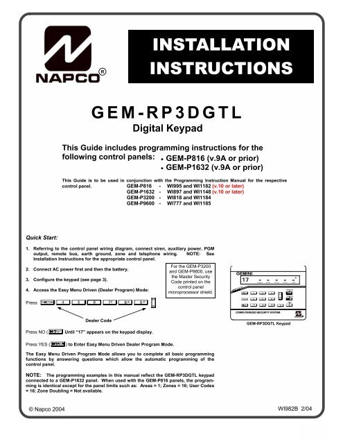
INSTALLATION<br />
INSTRUCTIONS<br />
<strong>GEM</strong>-<strong>RP3DGTL</strong><br />
<strong>Digital</strong> <strong>Keypad</strong><br />
This Guide includes programming instructions for the<br />
following control panels: • <strong>GEM</strong>-P816 (v.9A or prior)<br />
• <strong>GEM</strong>-P1632 (v.9A or prior)<br />
This Guide is to be used in conjunction with the Programming Instruction Manual for the respective<br />
control panel. <strong>GEM</strong>-P816 - WI995 and WI1182 (v.10 or later)<br />
<strong>GEM</strong>-P1632 - WI897 and WI1148 (v.10 or later)<br />
<strong>GEM</strong>-P3200 - WI818 and WI1184<br />
<strong>GEM</strong>-P9600 - WI777 and WI1185<br />
Quick Start:<br />
1. Referring to the control panel wiring diagram, connect siren, auxiliary power, PGM<br />
output, remote bus, earth ground, zone and telephone wiring. NOTE: See<br />
Installation Instructions for the appropriate control panel.<br />
For the <strong>GEM</strong>-P3200<br />
2. Connect AC power first and then the battery.<br />
and <strong>GEM</strong>-P9600, use<br />
the Master Security<br />
3. Configure the keypad (see page 3).<br />
Code printed on the<br />
control panel<br />
4. Access the Easy Menu Driven (Dealer Program) Mode:<br />
microprocessor shield.<br />
Press A456789 D<br />
<strong>GEM</strong>INI<br />
ARMED STATUS<br />
17<br />
INTERIOR<br />
SYSTEM ARMED<br />
01/01/97 12:00AM<br />
ENT A1<br />
BYPASS FIRE/TBL SYS TBL CHIME<br />
NEXT/YES<br />
A 123<br />
D E PRIOR/NO<br />
B 4 5 6 F<br />
AREA<br />
C 7 8 9 0 G<br />
Dealer Code<br />
Press NO (F Until “17” appears on the keypad display.<br />
COMPUTERIZED SECURITY SYSTEM<br />
<strong>GEM</strong>-<strong>RP3DGTL</strong> <strong>Keypad</strong><br />
Press YES (E) to Enter Easy Menu Driven Dealer Program Mode.<br />
The Easy Menu Driven Program Mode allows you to complete all basic programming<br />
functions by answering questions which allow the automatic programming of the<br />
control panel.<br />
NOTE: The programming examples in this manual reflect the <strong>GEM</strong>-<strong>RP3DGTL</strong> keypad<br />
connected to a <strong>GEM</strong>-P1632 panel. When used with the <strong>GEM</strong>-P816 panels, the programming<br />
is identical except for the panel limits such as: Areas = 1; Zones = 16; User Codes<br />
= 16; Zone Doubling = Not available.<br />
© <strong>Napco</strong> 2004<br />
WI982B 2/04<br />
1
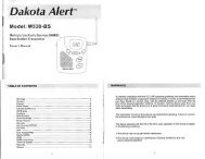
THE <strong>GEM</strong>-<strong>RP3DGTL</strong> KEYPAD<br />
DESCRIPTION<br />
The <strong>GEM</strong>-<strong>RP3DGTL</strong> is a dual 7-segment digital keypad that is compatible with the NAPCO <strong>GEM</strong>-Series <strong>GEM</strong>-P816,<br />
P1632, P3200 & P9600 control-panels. Refer to User Guide OI249 for operation instructions. While the <strong>GEM</strong>-<br />
<strong>RP3DGTL</strong> may be used to fully program the control, the <strong>GEM</strong>-RP1CAe2 keypad provides the optimum in ease of<br />
keypad programming. Note: Do not mix classic RP series keypads with "K Series" keypads within one system.<br />
ORDERING INFORMATION<br />
Note: Any of the following <strong>Napco</strong> wireless transmitters may be used with the <strong>GEM</strong>-RECV Series Receivers. Batteries<br />
are included with all transmitters.<br />
<strong>GEM</strong>-TRANS2 - Window/Door Sensor. This supervised, two-point transmitter provides an internal magnetic reed<br />
switch and/or terminals for two external normally-closed devices, or one external normally-open device.<br />
<strong>GEM</strong>-RECV8: Wireless Receiver, 8 Zones<br />
<strong>GEM</strong>-RTRANS: Recessed Window/Door Transmitter<br />
<strong>GEM</strong>-PIR - Wireless PIR Motion Sensor.<br />
<strong>GEM</strong>-PIRPET - Wireless 30 lb. pet immune PIR Motion Sensor.<br />
<strong>GEM</strong>-DT - Dual-technology PIR/microwave sensor.<br />
<strong>GEM</strong>-SMK - Wireless Photoelectric Supervised smoke detector.<br />
<strong>GEM</strong>-HEAT - Wireless Heat Detector 135°F / Rate of Rise.<br />
<strong>GEM</strong>-KEYF - Hand-Held Key Fob Transmitter. Key chain/Pendant remote arming or emergency transmitter.<br />
<strong>GEM</strong>-WP - Wireless Waterproof Panic Button.<br />
<strong>GEM</strong>-GB - Glass-break sensor.<br />
<strong>GEM</strong>-TRANS2 - 2-Point Window/Door Transmitter<br />
DL123A - Replacement Lithium Battery for <strong>GEM</strong>-TRANS2, <strong>GEM</strong>-PIR (2), <strong>GEM</strong>-PIRPET(2) and <strong>GEM</strong>-GB (2) (bulk<br />
packed).<br />
SPECIFICATIONS<br />
Operating Voltage: 12VDC (supplied by panel)<br />
Current Drain: 50 mA Standby<br />
Note: Subtract keypad current from combined auxiliary current of the control panel.<br />
Operating Temperature: 0° C to 49° C<br />
Storage Temperature: 20° C to + 85° C<br />
Power Requirements: 12VDC, 45mA (supplied by panel)<br />
Dimensions: 5 7/8" x 4 3/8" x 1" (WxHxD)<br />
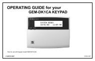
MOUNTING THE KEYPAD<br />
A keypad should be located near each exit/entry door. To open the case, insert a screwdriver into either slot at the<br />
bottom and push up with a slight twisting motion to release the retainer tab. Repeat for the other slot. Pull out at the<br />
bottom and lift off the two hooks at the top.<br />
The <strong>GEM</strong>-<strong>RP3DGTL</strong> features a handy pull-up reference label. (This label must be used in UL installations). Before<br />
mounting the keypad onto the wall, push the Sliding Label Plate (with label and felt backing affixed and handle facing<br />
forward) down the guides at the rear of the keypad until it snaps into place. Once installed, the Sliding Label Plate<br />
cannot be removed without first removing the keypad from the wall. Note: The keypad fire and panic keys should not<br />
be considered a substitute for a listed manual initiating device, such as a pull box.<br />
If installing onto a double-gang box, insert mounting screws through the two vertical elongated holes on the left side of<br />
the case and into the box. If the box is visible when viewed from the front, adjust the keypad vertically and tighten the<br />
screws. Then, using hardware suitable for the mounting surface, add one or two screws at the right side of the keypad<br />
case directly into the wall to ensure a secure installation. Note: Do not over tighten the screws! Uneven walls may<br />
cause the keypad case to distort.<br />
2<br />
For Sales and Repairs, call toll free: (800) 645-9445<br />
For direct line to Technical Service, call toll free: (800) 645-9440<br />
Internet: http://www.napcosecurity.com
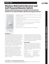
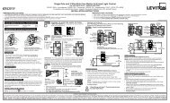
WIRING<br />
Connect the keypad wires to the control panel terminals shown in the table at the right.<br />
KEYPAD ADDRESS JUMPERS<br />
In summary, if more than one keypad is installed:<br />
• Each must be assigned a unique address (that is, no two keypads may be numbered<br />
alike).<br />
• <strong>Keypad</strong>s must be addressed consecutively (that is, missing numbers are not permitted).<br />
• Only <strong>Keypad</strong> No. 1 may be used for programming. (However, for ease of programming, it<br />
is recommended that a <strong>GEM</strong>-RP1CA / <strong>GEM</strong>-RP1CAe / <strong>GEM</strong>-RP1CAe2 be selected as<br />
<strong>Keypad</strong> #1).<br />
COLOR TERMINAL<br />
RED 9<br />
BLACK 10<br />
GREEN 11<br />
YELLOW 12<br />
WHITE* N/O PANIC<br />
WHITE* N/O PANIC<br />
* Cut and insulate 2 white<br />
wires if not used.<br />
KEYPAD OPTION JUMPERS<br />
Up to 7 <strong>GEM</strong>-<strong>RP3DGTL</strong> keypads may be connected to the control panel (<strong>Keypad</strong>s 1–7). Each must be configured for<br />
a keypad address. In addition, the keypad may be configured to disable touchpad backlight and entry sounder.<br />
<strong>Keypad</strong>s are configured by the proper selection of jumpers. Refer to the label on the keypad circuit board for jumper<br />
locations and a summary of settings.<br />
JUMPERS:<br />
A: DISABLE PUSHBUTTON BACKLIGHT<br />
Cut Jumper A to disable touchpad pushbutton back-lighting.<br />
C: DISABLE KEYPAD SOUNDER<br />
Cut Jumper C to disable the keypad sounder. (Do not disable in UL Installations)<br />
E: ENABLE KEYPAD TAMPER<br />
Cut Jumper E to convert the keypad Chime LED to a system Tamper LED (only with control panels which support<br />
system tamper).<br />
KEYPAD JUMPER SETTINGS<br />
NUMBER 1 2 3 PARK<br />
1 OFF or • •<br />
ON<br />
2 • ON STORE SPARE<br />
3 ON ON JUMPERS<br />
4 • • ON IN THIS<br />
5 ON • ON POSITION<br />
6 • ON ON<br />
7 ON ON ON<br />
3
EASY PROGRAM MODE OVERVIEW (Using a <strong>GEM</strong>-<strong>RP3DGTL</strong> <strong>Keypad</strong>)<br />
ENTERING THE EASY KEYPAD PROGRAM MODE<br />
1 Enter the Dealer Security Code (default = 456789) for a new panel or enter your custom Dealer Program Code if<br />
programmed and press A<br />
2 Press NO (F) repeatedly until function "17" (Activate Program Mode) is displayed.<br />
NOTE: If you pass "17" you can scroll back by pressing B.<br />
3 Press YES (E) to enter the Dealer Program Mode.<br />
Use the following guide to answer the Easy Program Mode questions which will quickly allow you to create a custom<br />
default program. Press A to set cursor, NEXT (E) to go forwards, PRIOR (F) to go backwards, D to<br />
save and C twice to exit the Easy Program Mode.<br />
ANSWERING A QUESTION IN THE EASY PROGRAM MODE<br />
The Easy Program Mode the questions will be in the form of a 2-digit number flashing in the digital display.<br />
Pressing A will set the cursor into the next field to answer the question.<br />
Using this book as a guide, enter the appropriate data in response to each question and then press D to save.<br />
If no additional programming is necessary for the question, press NEXT (E) to go to the next question.<br />
REVIEWING THE DATA ENTRY IN THE EASY PROGRAM MODE<br />
The data entered in response to an Easy Program Mode question may be reviewed before saving.<br />
• After entering the data before pressing D to save, A may be pressed until the 2 digit question number<br />
appears flashing in the display again.<br />
• Pressing A will step through all the fields of the question for review and will then result in the 2 digit question<br />
number flashing in the display again.<br />
! If the data is correct, press D to save.<br />
! If the data is not correct, press A to set the cursor into the next field and again enter the appropriate<br />
data.<br />
Note: The contents of an Easy Program Mode question may be reviewed after the initial programming of the control,<br />
with the exception of the questions which are marked (Appears for New Panel Only). These questions set up the<br />
basic structure of the control panel program (Number of zones in an area, etc.) and cannot be viewed or altered once<br />
set.<br />
EXITING THE DEALER PROGRAM MODE<br />
If in the Easy Program Mode, press C to enter the Direct Address Program Mode. Press C once again to<br />
end all programming and resume normal keypad operation.<br />
RESETTING THE CONTROL PANEL TO FACTORY DEFAULT<br />
If necessary, the control panel can be returned to the factory default and be re-programmed from scratch.<br />
• For the <strong>GEM</strong>-P816 and <strong>GEM</strong>-P1632, enter the Direct Address program mode, go to location 1198 and press D.<br />
(A1198D)<br />
4
NEXT/YES<br />
PRIOR/NO<br />
AREA<br />
R<br />
Programming the <strong>GEM</strong>-P816 & <strong>GEM</strong>-P1632 (v.9A and Earlier) with the <strong>GEM</strong>-<strong>RP3DGTL</strong><br />
Refer to the <strong>GEM</strong>-P9600/3200 Programming Manuals (WI1185 & WI1184) and follow the <strong>GEM</strong>-<strong>RP3DGTL</strong><br />
<strong>Keypad</strong> Easy Programming Mode instructions. The following applies to the <strong>GEM</strong>-P816/1632:<br />
01 INTERIOR<br />
(Direct Entry)<br />
BYPASS FIRE/TBL SYS TBL CHIME<br />
INTERIOR BYPASS FIRE/TBL SYS TBL CHIME<br />
Total Number of Zones in Area 1 (Appears for New Panel Only)<br />
Press the A button and then directly enter the total number of zones to<br />
be programmed for Area 1. Valid entries are from 01 to 32. Directly enter<br />
the total number of zones, including leading zeros. Use number buttons<br />
1 through 9. NOTE: Press the 0 button for a zero. The<br />
system is based on groups of 4 zones each (after the first 8 zones), and will<br />
automatically round up to the next group of 4. For example, if you enter 18, it<br />
will automatically convert this to 20 zones. Press D to save. Press NEXT<br />
(E) button to proceed. NOTE: If you are programming a 2 Area system,<br />
enter the total number of zones required for Areas 1 & 2. The Direct Address Program Mode can then be used to<br />
remove zones from Area 1 and place them in Area 2. See Zone Options. If Programming a Wireless Only system, or<br />
using wireless only on Zones 9-32, enter the total number of zones in system. Enter the transmitter points in the RF<br />
Transmitter section of the Easy Menu Driven Programming Mode.<br />
(Press YES or NO)<br />
Panel Zone Doubling(Appears for New Panel Only) (<strong>GEM</strong>-P1632 only)<br />
If the total number of zones in Area 1 entered was 16 or greater, press YES<br />
03 (E) to effectively double the capacity of the control panel's hard wired<br />
INTERIOR BYPASS FIRE/TBL SYS TBL CHIME<br />
zones from 8 to 16. The 16 zones can no longer use normally open devices<br />
but will be designated for Normally Closed devices only. The terminal for<br />
Zone 1 will now support Zones 1 and 9 with the use of the supplied EZ Zone<br />
INTERIOR BYPASS FIRE/TBL SYS TBL CHIME<br />
Doubling TM resistors, supplied. (Refer to Wiring Diagram and Installation<br />
Instructions). If Panel Zone doubling is not desired, press NO (F).<br />
NOTE: Answer NO for <strong>GEM</strong>-P816.<br />
04 INTERIOR<br />
(Press YES or NO)<br />
BYPASS FIRE/TBL SYS TBL CHIME<br />
INTERIOR BYPASS FIRE/TBL SYS TBL CHIME<br />
Fire Zones in Area 1 (Appears for New Panel Only) Press the A<br />
button and then directly enter the zone number of any zones which are to be<br />
used as Fire Zones (both 2-wire, 4-wire or wireless). Valid entries are from<br />
01 to 32. Directly enter each zone number, including leading zeros, and<br />
press D to save, and then repeat for any additional zone(s). Press NEXT<br />
(E) button to proceed.<br />
05 INTERIOR<br />
BYPASS FIRE/TBL SYS TBL CHIME<br />
INTERIOR BYPASS FIRE/TBL SYS TBL CHIME<br />
(Press YES or NO)<br />
2-Wire Fire Zones in Area 1 (Appears for New Panel Only) Press the<br />
A button and then directly enter the zone number of any Fire Zones<br />
(from previous question) which are to be used with 2-wire smoke detectors.<br />
The only valid entries are 07 and 08. Directly enter each zone number,<br />
including leading zeros. Press D to save and then repeat for any additional<br />
zone(s). NOTE: Only zones which have been designated as Fire Zones may<br />
be programmed as 2 Wire Fire zones. Press NEXT (E) button to<br />
proceed. NOTE: JP3 must be set to “2-WF” position for 2-wire fire zones for<br />
zones 7 and 8 (refer to Installation Instructions).<br />
(Yes or No)<br />
06<br />
<strong>GEM</strong>INI SYSTEM ARMED<br />
01/01/97 12:00AM ENT INTERIOR A1 BYPASS FIRE/TBL SYS TBL CHIME<br />
A 1 2 3<br />
D E<br />
B 4 5 6 F<br />
ARMED STATUS<br />
C 7 8 9 0<br />
G<br />
Report all Zones to Central Station(Appears for New Panel Only)<br />
Press YES (E) button for all zones to report to central station; press NO<br />
(F) button for no zones to report (LOCAL SYSTEM).<br />
COMPUTERIZED SECURITY SYSTEM<br />
INTERIOR BYPASS FIRE/TBL SYS TBL CHIME<br />
5
Programming the <strong>GEM</strong>-P816 & <strong>GEM</strong>-P1632 (v.9A and Earlier)<br />
07 INTERIOR<br />
(Direct Entry)<br />
BYPASS FIRE/TBL SYS TBL CHIME<br />
INTERIOR BYPASS FIRE/TBL SYS TBL CHIME<br />
Entry/Exit Zones in Area 1 (Appears for New Panel Only)<br />
Press the A button and then directly enter the zone number of any zones<br />
which are to be used as Entry/Exit zones. Valid entries are from 01 to 32.<br />
Directly enter each zone number, including leading zeros.<br />
Use number buttons 0 through 9.<br />
Press D to save and then repeat for any additional zone(s). Press NEXT (E)<br />
button to proceed. NOTE: Chime will automatically be programmed for all E/E zones.<br />
08 INTERIOR<br />
22 INTERIOR<br />
(Direct Entry)<br />
BYPASS FIRE/TBL SYS TBL CHIME<br />
INTERIOR BYPASS FIRE/TBL SYS TBL CHIME<br />
(Direct Entry)<br />
BYPASS FIRE/TBL SYS TBL CHIME<br />
INTERIOR BYPASS FIRE/TBL SYS TBL CHIME<br />
Interior Zones in Area 1 (Appears for New Panel Only)<br />
Press the A button and then directly enter the zone number of any zones<br />
which are to be used as Interior Zones. Valid entries are from 01 to 32.<br />
Directly enter each zone number, including leading zeros. Use number<br />
buttons 0 through 9. Press D to save and then repeat for any<br />
additional zone(s). Press NEXT (E) button to proceed. NOTE: All<br />
Interior zones will also be automatically programmed as “Exit/Entry Follower”<br />
zones.<br />
Number of <strong>Keypad</strong>s in Area 1<br />
Press the A button and then directly enter the total number of <strong>Keypad</strong>s<br />
to be installed in Area 1. Valid entries are from 01 to 07. Directly enter the<br />
number of keypads, including leading zeros. Use number buttons 0<br />
through 9. Press D to save . Press NEXT (E) button to proceed.<br />
NOTE: Area 2 keypads can only be assigned in Direct Address<br />
Programming. See <strong>Keypad</strong> Options.<br />
24 INTERIOR<br />
BYPASS FIRE/TBL SYS TBL CHIME<br />
Central Station Receiver 1 Telephone Number<br />
Press the A button and using the number buttons, directly enter telephone<br />
number of up to 16 digits including prefix, if necessary, for receiver 1.<br />
Central Station Receiver 1 Telephone Number<br />
INTERIOR BYPASS FIRE/TBL SYS TBL CHIME<br />
25 INTERIOR<br />
(Direct Entry)<br />
(Direct Entry)<br />
BYPASS FIRE/TBL SYS TBL CHIME<br />
NOTE: Central Station Receiver 2 and 3 Telephone Numbers can be entered<br />
in Direct Address Programming. See CS Reporting Options.<br />
Press D to save . Press NEXT (E) button to proceed.<br />
Central Station Receiver 1 Account Number<br />
Press the A button and then directly enter an account number of up to<br />
four digits.<br />
INTERIOR BYPASS FIRE/TBL SYS TBL CHIME<br />
Central Station Account #<br />
NOTE: Central Station Receiver 2 and 3 Account Numbers can be entered in<br />
Direct Address Programming. See CS Reporting Options.<br />
Press D to save. Press NEXT (E) button to proceed.<br />
For Central Station Telephone and Account Numbers: Use number buttons 1 through 9 for digits 1–9;<br />
press G0 for a zero and G 1 through G 5 for letters B–F, respectively. NOTE: Pre-Dial<br />
Delay = “D”; Dial-Tone Detection = “E”. Pressing the 0 button will produce a blank space (•).<br />
6
26 INTERIOR<br />
Programming the <strong>GEM</strong>-P816 & <strong>GEM</strong>-P1632 (v.9A and Earlier)<br />
BYPASS FIRE/TBL SYS TBL CHIME<br />
INTERIOR BYPASS FIRE/TBL SYS TBL CHIME<br />
(Direct Entry)<br />
Central Station Receiver 1 Format<br />
From the table below, enter the central station's receiver format. Use number<br />
buttons 1 through 9. NOTE: Press G0 for a zero and<br />
0 for a blank space (•). Press G 1 through G 4 for<br />
letters B–E, respectively. Press D to save. Press NEXT (E) button to<br />
proceed.<br />
NOTE: Central Station Receiver 2 and 3 Formats can only be entered in<br />
Direct Address Programming. See CS Receiver Options.<br />
DATA CS RECEIVER 1 FORMAT<br />
ENTRY<br />
•(blank) Ademco Slow, Silent Knight Slow<br />
2 Radionics Fast<br />
3 Silent Knight Fast<br />
4 Radionics, CD, Franklin Slow<br />
DATA CS RECEIVER 1 FORMAT<br />
ENTRY<br />
5 Universal High Speed<br />
B<br />
SIA<br />
C<br />
Ademco Point ID<br />
E<br />
Pager<br />
27 INTERIOR<br />
BYPASS FIRE/TBL SYS TBL CHIME<br />
INTERIOR BYPASS FIRE/TBL SYS TBL CHIME<br />
(Direct Entry)<br />
Enter User Codes<br />
For default program, enter up to 32 User Codes, with Area 1 and Area 2<br />
Options. Press the (A) button once to set the cursor to the User Code.<br />
Use the number buttons 0 through 9 to enter the User Number, followed<br />
by A and a User Code of up to 6 digits. Enter G0 for a blank.<br />
NOTE: If “Enable Global Ambush Code”(Address 0720) is enabled and<br />
“Global Ambush Code” (Address 1054) is left blank(•), do not program the<br />
first two digits of ANY User Code as '99'.<br />
A<br />
A<br />
User # User Code Area 1 Area2<br />
Options Options<br />
NOTE: When entering the Area 1<br />
and Area 2 options, press<br />
G0 for a ten. Enter 0<br />
for a blank.<br />
USER AREA OPTIONS - Select the desired Area Options (Area 1 and<br />
DATA ENTRIES OPTION ENABLED<br />
L R EXPLANATION<br />
blank(•) blank(•) Disabled User Code not active in this area.<br />
blank(•) 1 Arm/Disarm Allows User Code to arm/disarm this area.<br />
blank(•) 2 Arm Only Prevents User Code from disarming this area.<br />
blank(•) 3 Service A Service Code has restricted arm/disarm rights; if an area is armed with a Service Code, the area can be disarmed<br />
with any valid User Code, including a Service Code. If the area is armed with OTHER than a Service Code, it<br />
CANNOT be disarmed with a Service Code.<br />
blank(•) 4 Access This is normally used to activate a door striker while an area is disarmed. Also program “Access Control on PGM2<br />
Output” (Address 0719) and “PGM2 Output Access Control Timeout” (Address 0711).<br />
blank(•) Add 8 * User Program User Program Option is enabled for <strong>Keypad</strong> 1 only, wherever it is connected (Area 1 or Area 2).<br />
• Press D to save. To proceed to the next User Code, press the A button to set the cursor to the User Number<br />
and change it using the number buttons.<br />
• If the programmed code was less than 6 digits, enter blanks G0 for the remaining digits.<br />
Example: Program a code of “2222” for user 02, with area 1 options of “Arm/Disarm” and “User Program”:<br />
Enter 02 for the user number, 2222 G0 G0 for a user code,<br />
G09 “(blank) 9” for area 1 options and G0G0 “(blank) (blank)” for area 2 options.<br />
CHANGING OR CANCELING A CODE: To change any code, merely program over the existing code as described<br />
above and press D to save. Similarly, to cancel a code, blank out each number of the code press D to save.<br />
7
28 INTERIOR<br />
Programming the <strong>GEM</strong>-P816 & <strong>GEM</strong>-P1632 (v.9A and Earlier)<br />
BYPASS FIRE/TBL SYS TBL CHIME<br />
INTERIOR BYPASS FIRE/TBL SYS TBL CHIME<br />
(Direct Entry)<br />
RF Transmitter Programming<br />
(For wireless systems only. Also see Quick Method, which follows)<br />
Press the A button and for each transmitter (key fob transmitters also),<br />
then directly enter:<br />
1 The zone number (01–32) to which the transmitter will be mapped,<br />
including leading zeros. Press the A button again.<br />
2 The 6-digit RF ID # printed on the transmitter and box.<br />
3 The 1-digit checksum number (C) printed on the transmitter and box.<br />
4 The Point number (1–4) (P); enter “9” for unsupervised (all points).<br />
Press D to save. Then go to step 1 to enter next transmitter. When all<br />
transmitters are entered, press NEXT (E) button to proceed.<br />
A<br />
NOTE: When programming the RF ID number:<br />
“A” = G 0 ; “B” = G 1 ;<br />
Zone # 6-digit RF ID # Checksum # Point # “C” = G 2 ; “D” = G 3 ;<br />
“E” = G 4 ; “F” = G 5 .<br />
Quick Method. If a receiver is already installed in the panel, <strong>Napco</strong><br />
transmitter wireless points can be programmed automatically (“enrolled”) using the following procedure. NOTE: The<br />
transmitter point will be enrolled only if the signal strength is 3 or greater.<br />
1. Enter the zone number to which the transmitter point will be mapped.<br />
2. Press the B button to enter the Enroll Mode. The red and green LEDs on the keypad will flash.<br />
3. Open the loop of the point that is to be programmed (<strong>GEM</strong>-TRANS2 only).<br />
4. Install the transmitter battery. The keypad will beep once to indicate that the point has been successfully enrolled.<br />
Multi-point transmitters can be mapped to successive zones simultaneously (Example 1) or to selected zones point by<br />
point (Example 2):<br />
Example 1. A <strong>GEM</strong>-TRANS2 transmitter has the RF ID number 410078:1. Map both points to Zones 11–12,<br />
respectively.<br />
1. Enter the Enroll mode as described in step 2 above.<br />
2. Enter Zone “11”.<br />
3. Open the loops of points 1 and 2.<br />
4. Install the transmitter battery. The keypad will beep 3 times to indicate that three points have been programmed.<br />
• Transmitter 410078:1, point 1 will be mapped to Zone 11.<br />
• Transmitter 410078:1, point 2 will be mapped to Zone 12.<br />
The keypad will now display Zone 12, the last zone enrolled.<br />
Example 2. A <strong>GEM</strong>-TRANS2 transmitter has the RF ID number 287613:1. Map point 1 to Zone 6 and point 2 to Zone 9.<br />
1. Enter the Enroll mode as described above.<br />
2. Enter Zone “06”.<br />
3. Open point-1 loop.<br />
4. Install the battery. The keypad will beep once to indicate that one point has been programmed. (Transmitter<br />
287613:1, point 1 will be mapped to Zone 6.)<br />
5. Enter Zone “09”.<br />
6. Close point-1 loop and open point-2 loop.<br />
7. Remove the transmitter battery, then re-install it. The keypad will beep once to indicate that one point has been<br />
programmed. (Transmitter 287613:1, point 2 is mapped to Zone 9).<br />
8<br />
KEY FOB ZONE ASSIGNMENT: Key fobs can also be assigned to zones to allow multiple wireless panic buttons on<br />
one alarm system, each reporting to a central station, or pager while having a description on the keypad that describes<br />
the person holding the key fob, the location where the person holding the key fob is stationed, or the special purpose of<br />
the key fob button being depressed. See the next page on Key fob Zone Assignment.
29 INTERIOR<br />
A<br />
Programming the <strong>GEM</strong>-P816 & <strong>GEM</strong>-P1632 (v.9A and Earlier)<br />
BYPASS FIRE/TBL SYS TBL CHIME<br />
INTERIOR BYPASS FIRE/TBL SYS TBL CHIME<br />
(Direct Entry)<br />
A<br />
Key Fob Transmitters<br />
Keyfobs can be programmed as “Arm/Disarm” devices using the ON and<br />
OFF buttons (refer to control panel installation instructions).<br />
Press the A button and for each Key Fob Transmitter, enter:<br />
1 The Key Fob Transmitter number (01–15). Press A again.<br />
2 The area number to which transmitter is assigned (1 or 2); enter 0 to<br />
disable keyfob.<br />
3 The 6-digit RF ID # printed on the transmitter (enter all numbers and/or<br />
letters, including leading “0”s, if any).<br />
4 The 1-digit checksum number printed on transmitter.<br />
5 The Aux-1 Option (see key fob Aux 1 & Aux 2<br />
options).<br />
6 The Aux-2 Option (see key fob Aux 1 & Aux 2<br />
options).<br />
KeyFob # Area # 6-digit RF ID # Checksum # Aux1 #<br />
DATA AUX 1/AUX 2<br />
ENTRY OPTIONS<br />
•<br />
None<br />
(blank)<br />
1 Relay Group 1<br />
2 Relay Group 2<br />
9 <strong>Keypad</strong> Panic<br />
0 Aux K.P. Panic<br />
B Instant<br />
C Toggle Aux<br />
Relay<br />
D Access Control<br />
Press D to save. Then go to step 1 to enter next Key Fob.<br />
When all Key Fobs are entered, press NEXT (E) button to<br />
proceed.<br />
Note: If the Key Fob is converted for Two Button “Emergency Use”<br />
(by cutting an internal jumper), both top or bottom buttons must<br />
be depressed to activate an alarms. In this case, the Aux-1 and<br />
Aux-2 cannot be programmed.<br />
NOTE: When programming the ID Code<br />
number:<br />
“A” = G 0 ; “B” = G 1 ;<br />
“C” = G 2 ; “D” = G 3 ;<br />
“E” = G 4 ; “F” = G 5 .<br />
Key Fob Zone Assignment<br />
Each of the 4 key fob buttons can be assigned to a zone. For example, On button = point 1; Off button = point 2; A1 =<br />
point 3; A2 = point 4. Up to 32 key fobs (using 1 button) or 16 key fobs (using 2 buttons) or 8 key fobs (using all 4<br />
buttons) or any combination up to a maximum of 32 controlled zones can be assigned, providing multiple wireless panic<br />
buttons on a system, each reporting to the Central Station or a pager and/or annunciating on a keypad the key fob zone<br />
number with description/location. To assign a key fob to a zone: program the keyfob as you would a transmitter, entering<br />
the keyfob's ID code, check sum and point number at the appropriate zone. The “Quick Method” is not allowed. The<br />
zone may be hardwired to a sensor as well as assigned to a key fob (either one will activate the zone alarm output).<br />
NOTE: If assigning a key fob to a zone, the “ON/OFF” buttons on the key fob will no longer arm/disarm the system. The<br />
key fob is converted to a “panic only” device.<br />
ZONE DESCRIPTIONS: <strong>GEM</strong>-RF4RF cannot be used to enter Zone Descriptions. To enter Zone Descriptions you<br />
must use the <strong>GEM</strong>-RP1CAe2 <strong>Keypad</strong> or the <strong>Napco</strong> Quickloader Software.<br />
(Direct Entry)<br />
Dealer Code<br />
Press the A button directly enter the Dealer Code (default = 456789),<br />
including leading zeros. Use the 1 through 9 buttons. NOTE:<br />
33 INTERIOR BYPASS FIRE/TBL SYS TBL CHIME<br />
Press the 0 button for a zero. Press D to save.<br />
rE INTERIOR<br />
INTERIOR BYPASS FIRE/TBL SYS TBL CHIME<br />
BYPASS FIRE/TBL SYS TBL CHIME<br />
Re-enter the Dealer Code.<br />
Press D to save. Press NEXT (E) button to proceed.<br />
EXIT DEALER PROGRAM MODE: This completes the custom default program. Press the C button to enter the<br />
Direct Address Program Mode for further programming or press the C button once again to end all programming<br />
and resume normal keypad operation.<br />
9
DIRECT ADDRESS PROGRAM MODE<br />
This is an extension of the Dealer Program Mode. This method of programming is used in conjunction with the <strong>Keypad</strong><br />
Programming Worksheets contained in the control panel programming guide. Refer to these worksheets to identify the 4-<br />
digit location (address) of the feature to be programmed. An illustrative example is provided on the next page.<br />
KEYPAD PROGRAMMING OVERVIEW<br />
Direct Address Programming allows you to go directly to the<br />
address locations and change the data entries to customize your<br />
control panel options. Whereas the Easy Menu Program Mode is<br />
a simple quick start guide with limited options, the Direct Address<br />
Program Mode is more flexible allowing you to change all the<br />
options. It consists of multiple address locations with two data<br />
entry locations each (left and right) as shown in the adjacent<br />
diagram.<br />
ADDRESS<br />
LOCATIONS<br />
0000<br />
0000<br />
TO<br />
4095<br />
DATA ENTRY<br />
LOCATIONS<br />
LEFT DIGIT RIGHT DIGIT<br />
3 C<br />
HEXADECIMAL DATA:<br />
BLANK (•) = No Options<br />
1 to 9 = Entries 1 to 9<br />
0 = Entry of 10<br />
B to F = Entries 11 to 15<br />
ACCESSING DIRECT ADDRESS PROGRAM MODE<br />
17 INTERIOR<br />
BYPASS FIRE/TBL SYS TBL CHIME<br />
INTERIOR BYPASS FIRE/TBL SYS TBL CHIME<br />
(Direct Entry)<br />
1 Enter the Dealer Security Code (default = 456789) for a new panel or<br />
enter your custom Dealer Program Code if programmed.<br />
2 Press A<br />
3 Press NO (F) repeatedly until function "17" (Activate Program<br />
Mode) is displayed.<br />
4 Press YES (E) to enter the Dealer Easy Program Mode.<br />
5 Press C to enter the Dealer Address Program Mode.<br />
ENTERING DATA IN THE ADDRESS PROGRAM MODE<br />
1 Press A<br />
2 Enter the 4 digit Address location<br />
3 Enter the 2 digit data<br />
4 Press D to save.<br />
A<br />
Address #<br />
Data<br />
D<br />
EXAMPLE: Program an Alarm Timeout of 30 seconds.<br />
Press A0712 1G4 D<br />
• Alarm Timeout location = 0712<br />
• 30 second timeout = 1E<br />
Use 0 -9<br />
for digits 0 - 9<br />
Use 1 -9 for digits 1 - 9<br />
BLANK= 0<br />
A/10 = G 0<br />
B = G 1<br />
C = G 2<br />
D = G 3<br />
E = G 4<br />
F = G 5<br />
10
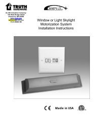
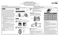
MOUNTING TEMPLATE<br />
2 3/8”<br />
4 3/8”<br />
TAMPER (DO<br />
NOT CUT OR<br />
DRILL WALL)<br />
KEYPAD BUS<br />
WIRES<br />
11
NAPCO SECURITY SYSTEMS, INC. (NAPCO)<br />
warrants its products to be free from manufacturing<br />
defects in materials and workmanship for thirty-six<br />
months following the date of manufacture. NAPCO will,<br />
within said period, at its option, repair or replace any<br />
product failing to operate correctly without charge to the<br />
original purchaser or user.<br />
This warranty shall not apply to any equipment, or any<br />
part thereof, which has been repaired by others,<br />
improperly installed, improperly used, abused, altered,<br />
damaged, subjected to acts of God, or on which any<br />
serial numbers have been altered, defaced or removed.<br />
Seller will not be responsible for any dismantling or<br />
reinstallation charges.<br />
THERE ARE NO WARRANTIES, EXPRESS OR<br />
IMPLIED, WHICH EXTEND BEYOND THE<br />
DESCRIPTION ON THE FACE HEREOF. THERE IS<br />
NO EXPRESS OR IMPLIED WARRANTY OF<br />
MERCHANTABILITY OR A WARRANTY OF FITNESS<br />
FOR A PARTICULAR PURPOSE. ADDITIONALLY,<br />
THIS WARRANTY IS IN LIEU OF ALL OTHER<br />
OBLIGATIONS OR LIABILITIES ON THE PART OF<br />
NAPCO.<br />
Any action for breach of warranty, including but not<br />
limited to any implied warranty of merchantability, must<br />
be brought within the six months following the end of<br />
the warranty period.<br />
IN NO CASE SHALL NAPCO BE LIABLE TO ANYONE<br />
FOR ANY CONSEQUENTIAL OR INCIDENTAL<br />
DAMAGES FOR BREACH OF THIS OR ANY OTHER<br />
WARRANTY, EXPRESS OR IMPLIED, EVEN IF THE<br />
LOSS OR DAMAGE IS CAUSED BY THE SELLER'S<br />
OWN NEGLIGENCE OR FAULT.<br />
In case of defect, contact the security professional who<br />
installed and maintains your security system. In order to<br />
exercise the warranty, the product must be returned by<br />
the security professional, shipping costs prepaid and<br />
insured to NAPCO. After repair or replacement, NAPCO<br />
assumes the cost of returning products under warranty.<br />
NAPCO shall have no obligation under this warranty, or<br />
otherwise, if the product has been repaired by others,<br />
improperly installed, improperly used, abused, altered,<br />
damaged, subjected to accident, nuisance, flood, fire or<br />
acts of God, or on which any serial numbers have been<br />
altered, defaced or removed. NAPCO will not be<br />
responsible for any dismantling, reassembly or<br />
reinstallation charges.<br />
This warranty contains the entire warranty. It is the sole<br />
warranty and any prior agreements or representations,<br />
whether oral or written, are either merged herein or are<br />
expressly cancelled. NAPCO neither assumes, nor<br />
12<br />
WARRANTY<br />
authorizes any other person purporting to act on its<br />
behalf to modify, to change, or to assume for it, any<br />
other warranty or liability concerning its products.<br />
In no event shall NAPCO be liable for an amount in<br />
excess of NAPCO's original selling price of the product,<br />
for any loss or damage, whether direct, indirect,<br />
incidental, consequential, or otherwise arising out of any<br />
failure of the product. Seller's warranty, as hereinabove<br />
set forth, shall not be enlarged, diminished or affected<br />
by and no obligation or liability shall arise or grow out of<br />
Seller's rendering of technical advice or service in<br />
connection with Buyer's order of the goods furnished<br />
hereunder.<br />
NAPCO RECOMMENDS THAT THE ENTIRE SYSTEM<br />
BE COMPLETELY TESTED WEEKLY.<br />
Warning: Despite frequent testing, and due to, but not<br />
limited to, any or all of the following; criminal tampering,<br />
electrical or communications disruption, it is possible for<br />
the system to fail to perform as expected. NAPCO does<br />
not represent that the product/system may not be<br />
compromised or circumvented; or that the product or<br />
system will prevent any personal injury or property loss<br />
by burglary, robbery, fire or otherwise; nor that the<br />
product or system will in all cases provide adequate<br />
warning or protection. A properly installed and<br />
maintained alarm may only reduce risk of burglary,<br />
robbery, fire or otherwise but it is not insurance or a<br />
guarantee that these events will not occur.<br />
CONSEQUENTLY, SELLER SHALL HAVE NO<br />
LIABILITY FOR ANY PERSONAL INJURY,<br />
PROPERTY DAMAGE, OR OTHER LOSS BASED ON<br />
A CLAIM THE PRODUCT FAILED TO GIVE<br />
WARNING. Therefore, the installer should in turn advise<br />
the consumer to take any and all precautions for his or<br />
her safety including, but not limited to, fleeing the<br />
premises and calling police or fire department, in order<br />
to mitigate the possibilities of harm and/or damage.<br />
NAPCO is not an insurer of either the property or safety<br />
of the user's family or employees, and limits its liability<br />
for any loss or damage including incidental or<br />
consequential damages to NAPCO's original selling<br />
price of the product regardless of the cause of such loss<br />
or damage.<br />
Some states do not allow limitations on how long an<br />
implied warranty lasts or do not allow the exclusion or<br />
limitation of incidental or consequential damages, or<br />
differentiate in their treatment of limitations of liability for<br />
ordinary or gross negligence, so the above limitations or<br />
exclusions may not apply to you. This Warranty gives<br />
you specific legal rights and you may also have other<br />
rights which vary from state to state.