Bandpass Filters Using Parallel Coupled Stripline Stepped ...
Bandpass Filters Using Parallel Coupled Stripline Stepped ...
Bandpass Filters Using Parallel Coupled Stripline Stepped ...

Create successful ePaper yourself
Turn your PDF publications into a flip-book with our unique Google optimized e-Paper software.
ZSFZETRANSACTIONS ON MICROWAVE TZZSORY AND ‘Z13CZZNZQUZZS,VOL. MIT-28, NO. 12, DZZCRMBER1980<br />
1413<br />
<strong>Bandpass</strong> <strong>Filters</strong> <strong>Using</strong> <strong>Parallel</strong> <strong>Coupled</strong><br />
<strong>Stripline</strong> <strong>Stepped</strong> Impedance Resonators<br />
MITSUO MAKIMOTO b SADAHIKO YAMASHITA, MEMBER, IE1311<br />
Ahtruet-Approxbnate dedgn foz’zntzb for baodpas futem Uebtg<br />
parallelcoupled striplbte etepped bpdance reeonatore (SIR) are derived.<br />
‘l%e fornudas take into account the arbitrary coupling length se weUas<br />
qumtef-wavele~ eoupfingoSozneadvantage of thfe filter are its amities<br />
tocentrolepurfooe reaponeeand ineertionloea bychaz@ngtbe etmetweof<br />
the remnator. using tbe (k3@zl fornudae iwo qerimental futez9 were<br />
de9kMf and fabricated and their pfN’fOMUIOCeS Closely matched design<br />
data.<br />
—%=z(el.e, ) +<br />
- e,<br />
22 z, 2.<br />
K+, >1<br />
07 zw<br />
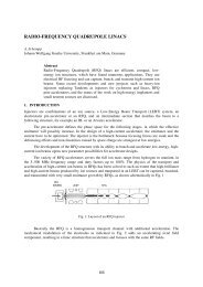
I. lNTRODIXTION<br />
T<br />
HE CENTER frequency of the seeond passband of<br />
bandpass filters with half-wavelength resonators is<br />
two or three times that of the fundamental frequency.<br />
This results in poor harmonic suppression when used as<br />
output filters in oscillators or amplifiers. To overcome this<br />
problem, the use of nonuniform line resonators as a filter<br />
element was considered [1]. Tle tapered transmission line<br />
resonator is well known as one of these resonators, but it<br />
is not sufficiently practical for multistage bandpass filter<br />
application.<br />
This paper describes a stepped impedance resonator<br />
(SIR) [2] used as a nonuniform transmission line resonator<br />
and its application to bandpass filters with the stripline<br />
construction.<br />
Firstly, fundamental parameters such as resonance<br />
characteristics of an SIR and slope parameters are derived.<br />
Secondly, the design formulas of a bandpass filter<br />
was derived from the admittance inverter which is in a<br />
coupling circuit with arbitrary coupled electrical length.<br />
Finally, to verify the design formulas two experimental<br />
bandpass filters were designed and fabricated. The experimental<br />
performance data are shown to be in close agreement<br />
with the design data.<br />
II.<br />
RESONANCEPROPERTIESOF SIR<br />
This section discusses the conditions of fundamental<br />
and spurious resonance of the SIR. The resonator structure<br />
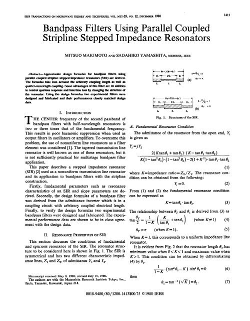
to be considered here is shown in Fig. 1. The SIR is<br />
symmetrical and has two different characteristic impedance<br />
lines, 21 and 22, of admittance Y, and Y2.<br />
., 2, 21<br />
(b)<br />
Fig. 1. Structures of the SIR.<br />
A. Fundamental Resonance Condition<br />
The admittance of the resonator from the open end, ~<br />
is given<br />
~ =jY2<br />
as<br />
2( Ktan01 +tan02) ”(K-tan01”tan02)<br />
K(l–tan201)”(l –tan282)-2(l +K2).tan01”tan62<br />
where K= impedance ratio= 22 /21. The resonance condition<br />
can be obtained from the following:<br />
(1)<br />
q=o. (2)<br />
From (1) and (2) the fundamental resonance condition<br />
can be expressed<br />
as<br />
K= tan 010tanf32. (3)<br />
The relationship between 0= and 01 is derived from (3) as<br />
e= 1 K<br />
tan~ = — o — + tan 61<br />
1–K ( tan~l )<br />
(when K+ 1) (4)<br />
e==~ (when K= 1). (5)<br />
When K= 1, this corresponds to a uniform impedance line<br />
resonator.<br />
It is evident from Fig. 2 that the resonator length /3=has<br />
minimum value when O 1. This condition can be obtained by differentiating<br />
(4) by 191,<br />
Manuscript reaived May 8, 1980; revised July 15, 1980.<br />
The authors are with the Matsushita Research Institute Tokyo, Inc.,<br />
Ikutaj Tama-kw Kawasaki, Japan 214.<br />
then<br />
~.(tan20, -K).sin20, =0 (6)<br />
O1=tan-l(~K )=02. (7)<br />
0018-9480/80/ 1200- 1413$00.75 01980 IEEE
1414 IEEE TRANSACTIONS ON M2CROWAVS THSORY AND TECHNIQUES, VOL. M’IT-28, NO. 12, DECSMSSR 1980<br />
5<br />
4<br />
~ 9A0<br />
%3 fs2/fo<br />
E<br />
2<br />
f sl&<br />
‘o 0.5 1.0 1.5 2.0<br />
Impedance Ratio K<br />
Fig. 3. Spurious resonance frequency of the SIR.<br />
pedance ratio K, and this is one of the special features of<br />
the SIR.<br />
(31<br />
Fig. 2. Resonance condition of the SIR.<br />
The above equation is the condition that 0~ has maximum<br />
or minimum value for constant K. For practical application<br />
it is preferable to choose 191= /3z because the design<br />
equations can be simplified considerably. Therefore, in<br />
the following discussion, the SIR is treated as having<br />
81= /32=0, and (1) can be expressed as<br />
y =jY2<br />
2(l+K). (K–tan20). tan0<br />
(8)<br />
K–2(l+K+K2) .tan20+Ktan4/3 “<br />
The resonance condition is then given, using the fundamental<br />
frequency ~0 and corresponding length 00, as<br />
tan280 = K<br />
III. SUSCEPTANCE SLOPE PARAMETER OF THE SIR<br />
As a basis for establishing the resonance properties of<br />
resonators regardless of their form it is convenient to<br />
specify their resonant frequency tio and their slope parameter<br />
[4]. For any resonator involving a shunt-type resonator<br />
the susceptance slope parameter can be expressed as<br />
(12)<br />
where B is the susceptance of the resonator. For the SIR<br />
considered here (12) becomes<br />
6 dB<br />
b=~.—<br />
2 d9 e=e. ”<br />
(13)<br />
Differentiating (8) by 0, we obtain the following simple<br />
equation:<br />
or<br />
oo=tan-l~. (9)<br />
b=$’”2(l+K)”<br />
A.Yz<br />
l+K<br />
=200Y2. (14)<br />
B. Spurious Resonance Frequency<br />
Taking the spurious resonance frequency to be j&(n =<br />
1,2,3,. ..) and corresponding 0 with O,n(n = 1,2,3, ” “ o), we<br />
obtain from (8) and (2)<br />
tan 0,, =00<br />
The slope parameter for a half-wavelength resonator<br />
with uniform characteristic impedance Zo( = 1/ Yo) can be<br />
induced from (14) in the case of 00 = 7r/4 and Y2 = Yo, and<br />
we obtain the following well-known equation as [3], [4]<br />
b=; Yo. (15)<br />
then<br />
tan2 0,2 – K=<br />
O<br />
tane=3=o<br />
(lo)<br />
IV. PARALLEL COUPLED SECTION<br />
This section considers a parallel coupled transmission<br />
line with arbitrary length and its equivalent circuit. For<br />
designing bandpass filters with SIR in which lines are<br />
coupled in parallel, it is necessary to find the relationship<br />
between even and odd mode impedance in the parallel<br />
coupled sections and the admittance inverter parameters<br />
[3].<br />
(11)<br />
The above results are shown in Fig. 3 as a function of<br />
the impedance ratio K. It becomes evident from Fig. 3<br />
that the spurious response can be controlled by the im-<br />
A. <strong>Parallel</strong> <strong>Coupled</strong> Section as an Admittance Inverter<br />
Fig. 4 (a) shows even and odd mode impedance Zoe,<br />
ZOO of a coupled line of electrical length 0, and the<br />
equivalent circuit is expressed by two single transmission<br />
lines of electrical length /3, impedance Z. and admittance
MAK2MOT0 AND YAMASH2TA: BANDPASS FILTERS AND STSPPED 2MPEDANCE RESONATORS 1415<br />
(a) ~<br />
@)<br />
.Zoe zoo<br />
20 20<br />
J<br />
( Zoe)nl<br />
i;OoG<br />
(Z0e)12<br />
W Zo- ~ , (.3W)12<br />
rr<br />
e ze e<br />
w=4e<br />
(208)<br />
23<br />
~1 (2m)23<br />
D+’<br />
..<br />
‘.\<br />
(Zoeh, n.1<br />
‘. (Zm)n, n. I<br />
‘==ZZI<br />
-9&<br />
Fig. 5. <strong>Bandpass</strong> filter structure using the SIR.<br />
Fig. 4. <strong>Parallel</strong> coupled fine and its equivalent with an inverter.<br />
ZO/K=J/YO (K= impedance inverter parameter).<br />
inverter parameter J, as shown in Fig. 4 (b). The ABCD<br />
matrix for Fig. 4 (a) and (b) can be expressed as The above two equations coincide with Cohn’s results 13].<br />
where<br />
[q]=<br />
IZoe + zoo ~oso ~(zoe–zoo)’+(zoe +zoo)’”cos’e<br />
Zoe – zoo<br />
2(ZO= – Zoo). sin~<br />
2 sin O Zoe +Zoo<br />
JZoe – zoo<br />
Zoe – zoo<br />
1 Cos 0<br />
I (Jz’’++J”sin’”cOse<br />
j Jz~ Sin’6 – $COS2@<br />
( )<br />
“<br />
( 1<br />
(17)<br />
—sin’O–JCOS29<br />
J JZ; ) (Jz’’++i)”sin’”cOs’ “<br />
[%1= ~<br />
Then equalizing each corresponding matrix element, we<br />
can obtain<br />
25:c0se=(Jz’’+a”sine”c0se<br />
’18)<br />
(Zoe –zoo)’+ (Zoe +Zoo)’.cos’ e =Jz’sin’ ~_ ~cos’ ~<br />
o<br />
2(ZOe –ZOO) sin/3<br />
J<br />
2sin/3 1<br />
ZOe – ZOO = Jz;<br />
(19)<br />
.sin26–Jcos2 0. (20)<br />
The above simultaneous equations are not independent of<br />
each other, and any two equations among the three are<br />
valid for solution. Solving (18) and (20), we obtain<br />
z oe<br />
l+(J/Yo)cosec O+(J/Yo)2<br />
~=<br />
l–(J/Yo)2cot20<br />
z .O _ l–(J/Yo)cosec6+ (J/Yo)2<br />
20<br />
1 –(J/Yo)2cot20 “<br />
These are generalized expressions for parallel coupled<br />
lines with arbitrary length.<br />
(21)<br />
(22)<br />
In the special case of quarter-wavelength coupling, by<br />
considering the situation O= 7r/2 in (21) and (22) then the<br />
following<br />
can be obtained:<br />
(23)<br />
%=1+(2)+(%9’<br />
%’=+9+(3’<br />
(24)<br />
“<br />
B. Admittance Inverter Parameters for <strong>Bandpass</strong> <strong>Filters</strong><br />
The fundamental configuration of an n-stage bandpass<br />
(16)<br />
filter considered here is shown in Fig. 5, and slope parameters<br />
for all resonators are of equal value, Z3(Z3= 200YO).<br />
When element values gj and relative bandwidth w are<br />
given as fundamental design parameters of a bandpass<br />
filter [4], the admittance inverter parameter ~,j+, can be<br />
expressed<br />
. —,,..––-<br />
as<br />
JO,=E=YOE<br />
dbjbjb ,<br />
2wf30<br />
+,j+l =W — =Yo (j=l-n-1)<br />
gjtifj+ 1<br />
G<br />
‘nn+=E=yoE ‘2’)<br />
<strong>Using</strong> (21) and (22) in the previous section, the design<br />
data for coupling lines can be obtained. It is then possible<br />
to design a bandpass filter as a SIR.<br />
V. EXPERIMENTAL FILTERS<br />
This section describes the design and performance of<br />
experimental filters. Two kinds of filters were designed<br />
and fabricated to verify the design formulas discussed<br />
above. The impedance ratio K was chosen to be 0.5 for<br />
the Tv~e 1 filter and 1.5 for the Tv~e 2 filter.<br />
1416<br />
IEEE TRANSACTIONS ON MICROWAVE THF30RY AND TECHNIQUES, VOL. MJT-28, NO. 12, D33C23MBSR 1980<br />
(d E<br />
o<br />
10<br />
,’<br />
,’<br />
;<br />
Fig. 6. Photograph of the expenmentaf SIR bandpass filters (left: Type . .<br />
1, “right: Type 2). “<br />
TABLE<br />
VAR20US PARAMETERS FOR DBSIGNJNG EXPERIMENTAL<br />
I<br />
FILTSRR<br />
Lo<br />
50 ‘gw<br />
1<br />
Frequercy<br />
lCOO 1100<br />
(t4tiz)<br />
Fig. 7. Measured frequency response of the experimental filters.<br />
Type - 1 Type - 2<br />
Impedance Ratio K 0.50 1.50<br />
Line Impedance<br />
Z1 m) 100 33.3<br />
Z2 (n) 50 50<br />
Resonator Length<br />
er (deg. )<br />
Slgpe Parameter<br />
141<br />
203<br />
1 J<br />
1 2 3<br />
4 (GHz)<br />
Fig. 8. Measured spurious response of the Type 1 filter.<br />
b<br />
(Mho)<br />
0.0246<br />
0.0354<br />
Even, Odd Mode<br />
(dB)<br />
Impedance (fl )<br />
(<br />
(Zoe)ol= (Z0e)45<br />
(ZOO)O1 = (Z00)45<br />
S8.43<br />
35.61<br />
80.67<br />
37.08<br />
(<br />
(Z0e)12 = (Zoe) 34<br />
(Zm)iz = (zoo) 34<br />
55.06<br />
45.79<br />
55.46<br />
45.53<br />
1 2 3 4<br />
( GHz)<br />
53.63<br />
53.91<br />
Frequent<br />
y<br />
46.83<br />
46.62<br />
Fig. 9. Measured spurioas response of the Type 2 filter.<br />
A. Design Parameters<br />
On the basis of the derived formulae two experimental<br />
filters were designed using the following parameters:<br />
center frequency ~=1.00GHz<br />
number of resonators N= 4<br />
response<br />
Chebyshev<br />
passband ripple R=O.01 dB<br />
relative bandwidth W=O.04<br />
and impedance ratio K<br />
K=O.50 (for Type 1 filter)<br />
K= 1.50 (for Type 2 filter).<br />
Various calculated design parameters are listed in Table I.<br />
The filters were fabricated with a substrate having a<br />
dielectric constant of c,= 2.6, and a triplate strip-line<br />
structure [5] in which the distance between ground planes<br />
was 3.15 mm. The arrangement of filters is shown in Fig.<br />
6. Each resonator has a hairpin structure [6], but spacing<br />
between line ~airs constitutirw the haimin resonator is<br />
. .<br />
wide enough to discount coupling between the line pairs.<br />
The actual dimensions of the resonator must be determined<br />
by taking into consideration end and junction<br />
effects of striplines [7], [8].<br />
B. Performance of Experimental <strong>Filters</strong><br />
Fig. 7 shows the attenuation characteristics of experimental<br />
filters. The measured fractional bandwidths are<br />
slightly more (around 10 percent) than the designed values.<br />
The midband insertion losses are 2.8 dB and 2.0 dB<br />
for Type 1 (k= 0.5) and Type 2 (k= 1.5), respectively.<br />
This is caused by a difference in the stripline width of the<br />
21 section where current has maximum value.<br />
The spurious responses of experimental filters are shown<br />
in Fig. 8 and Fig. 9 for K= 0.5 and 1.5, respectively. There<br />
is no distinct response around 2 fo, 3f0, and 4f0 k both<br />
figures, and these filters are considered to be effective for<br />
harmonic suppression as output filters of amplifiers or<br />
oscillators. The measured center frequency of the spurious<br />
passbands are listed in Table II compared with calculated
MAK2MOT0 AND YAMASHITA: BAN33PASS FILTSRS AND STEPPED 3MPEDANCE RESONATORS 1417<br />
TABLE II<br />
CALCULATEDANDMEASI.JRSD VALUBSOFSPURIOUSRBSONANCE<br />
FRSQUSNCY<br />
line and quarter wavelength coupling, can be obtained<br />
from equations presented here as a special case in which<br />
K= 1.0 and coupling length O= 90°. Therefore, the design<br />
method described in this paper is considered to involve<br />
generalized equations for parallel coupled stripline resonator<br />
filters.<br />
ACKNOWLEDGMENT<br />
fs3<br />
u 511 fo 520fo I<br />
355 fo 3.55 fo<br />
values, and it shows that there is close agreement between<br />
them.<br />
From the above experimental results it must be noted<br />
that the performance of bandpass filters using SIR depends<br />
on its structures, or the K value. In design practice<br />
it is desirable to choose a value for K of less than 1 if<br />
compactness or wide stop band characteristics are desired,<br />
and it is appropriate to choose a K value of more than 1 if<br />
low loss characteristics are important.<br />
VI.<br />
CONCLUSIONS<br />
A method of designing bandpass filters suitable for<br />
striplines with stepped impedance resonators (SIR) was<br />
established and fabricated filter performance closely<br />
coincided with design data.<br />
A special feature of this filter is that the spurious<br />
response and insertion loss can be controlled by the<br />
impedance ratio K of the resonator.<br />
Design equations for a conventional filter [3] using a<br />
parallel coupled stripline resonator, which has uniform<br />
The authors wish to thank Dr. S. Kisaka and Dr. H.<br />
Maeda for their encouragement.<br />
[1]<br />
[2]<br />
[3]<br />
[4]<br />
[5]<br />
[6]<br />
[7]<br />
[8]<br />
IG3FEMNCES<br />
C. P. Womack, “The use of exponential transmission lines in<br />
microwave components; IRE Trans. Microwave Theoy Tech., vol.<br />
MTT-10, pp. 124-132, Mar. 1962.<br />
M. Makimoto and S. Yamashita, “Compact bandpass filters using<br />
stepped impedance resonators; Prvc. ZEEE, vol. 67, pp. 16-19,<br />
Jan. 1979.<br />
S. B. Cohnj “<strong>Parallel</strong> coupled transmission-line-resonator filters~<br />
IRE Trans. Microwave Theory Tech., vol. MTT-6, pp. 223–231, Apr.<br />
1958.<br />
G. L. Matthaei, L. Young, and E. M. T. Jones, Microwave <strong>Filters</strong>,<br />
Inrpealmce-Matching Networks, and Coupling Structures. New<br />
York: McGraw-Hill, 1964.<br />
S. B. Cohn, “Shielded coupled-strip transmission line; ZRE Trans.<br />
Microwave Theory Tech., vol. M’IT-3, pp. 29-38, Oct. 1955.<br />
E. G. Cristal and S. Frankel “Hair-pin-line and hybrid hair-pinline/half-wave<br />
parallel-coupled-line filter$” ZEEE Trans. Microwaoe<br />
Theory Tech., vol. MTT-20, pp. 7 19–728, Nov. 1972.<br />
H. M. Altschuler and A. A. Oliner, “Discontinuity in the center<br />
conductor of symmetric strip transmission line,” ZRE Trans. Microwave<br />
Theoty Tech., vol. MIT-8, pp. 328–339, May 1960.<br />
V. Nalbandian and W. Steenarrt, “Discontinuities in symmetric<br />
strip-lines due to impedance step and their compensations: IEEE<br />
Trans. Microwave Theory Tech., vol. MTT-20, pp. 573-578, Sept.<br />
1972.