Fan Arrangements Rotation Discharge and Motor Position
Fan Arrangements Rotation Discharge and Motor Position
Fan Arrangements Rotation Discharge and Motor Position

You also want an ePaper? Increase the reach of your titles
YUMPU automatically turns print PDFs into web optimized ePapers that Google loves.
FAN ENGINEERING<br />
Information <strong>and</strong> Recommendations for the Engineer<br />
<strong>Fan</strong> <strong>Arrangements</strong>, <strong>Rotation</strong>,<br />
<strong>Discharge</strong> <strong>and</strong> <strong>Motor</strong> <strong>Position</strong><br />
FE-3900<br />
Introduction<br />
<strong>Fan</strong> arrangements <strong>and</strong> classes are industry st<strong>and</strong>ards that have been determined by AMCA (Air Movement <strong>and</strong> Control<br />
Association) to communicate the operating condition that a fan is capable of, the location of the bearings, <strong>and</strong> drive<br />
configurations.<br />
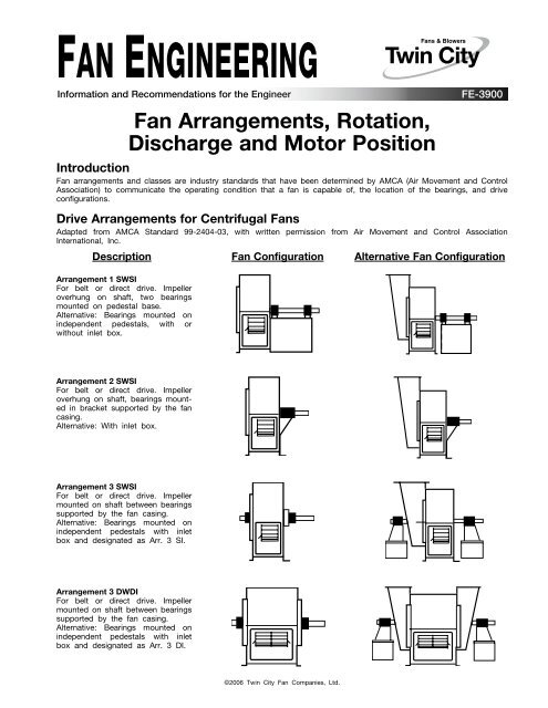
Drive <strong>Arrangements</strong> for Centrifugal <strong>Fan</strong>s<br />
Adapted from AMCA St<strong>and</strong>ard 99-2404-03, with written permission from Air Movement <strong>and</strong> Control Association<br />
International, Inc.<br />
Description <strong>Fan</strong> Configuration Alternative <strong>Fan</strong> Configuration<br />
Arrangement 1 SWSI<br />
For belt or direct drive. Impeller<br />
overhung on shaft, two bearings<br />
mounted on pedestal base.<br />
Alternative: Bearings mounted on<br />
independent pedestals, with or<br />
without inlet box.<br />
Arrangement 2 SWSI<br />
For belt or direct drive. Impeller<br />
overhung on shaft, bearings mounted<br />
in bracket supported by the fan<br />
casing.<br />
Alternative: With inlet box.<br />
Arrangement 3 SWSI<br />
For belt or direct drive. Impeller<br />
mounted on shaft between bearings<br />
supported by the fan casing.<br />
Alternative: Bearings mounted on<br />
independent pedestals with inlet<br />
box <strong>and</strong> designated as Arr. 3 SI.<br />
Arrangement 3 DWDI<br />
For belt or direct drive. Impeller<br />
mounted on shaft between bearings<br />
supported by the fan casing.<br />
Alternative: Bearings mounted on<br />
independent pedestals with inlet<br />
box <strong>and</strong> designated as Arr. 3 DI.<br />
©2006 Twin City <strong>Fan</strong> Companies, Ltd.
Drive <strong>Arrangements</strong> for Centrifugal <strong>Fan</strong>s (continued)<br />
Description <strong>Fan</strong> Configuration Alternative <strong>Fan</strong> Configuration<br />
Arrangement 4 SWSI<br />
For direct drive. Impeller overhung<br />
on motor shaft. No bearings on fan.<br />
<strong>Motor</strong> mounted on base.<br />
Alternative: With inlet box.<br />
Arrangement 7 SWSI<br />
For coupling drive. Generally the<br />
same as Arrangement 3, with base<br />
for the prime mover.<br />
Alternative: Bearings mounted on<br />
independent pedestals with inlet<br />
box <strong>and</strong> designated as Arr. 7 SI.<br />
Arrangement 7 DWDI<br />
For coupling drive. Generally the<br />
same as Arrangement 3, with base<br />
for the prime mover.<br />
Alternative: Bearings mounted on<br />
independent pedestals with inlet<br />
box <strong>and</strong> designated as Arr. 7 DI.<br />
Arrangement 8 SWSI<br />
For direct drive. Generally the same<br />
as Arrangement 1, with base for<br />
the prime mover.<br />
Alternative: Bearings mounted on<br />
independent pedestals, with or<br />
without inlet box.<br />
Arrangement 9 SWSI<br />
For belt drive. Impeller overhung<br />
on shaft, two bearings mounted on<br />
pedestal base. <strong>Motor</strong> mounted on<br />
the outside of the bearing base.<br />
Alternative: With inlet box.<br />
Arrangement 10 SWSI<br />
For belt drive. Generally the same<br />
as Arrangement 9 with motor<br />
mounted inside of the bearing pedestal.<br />
Alternative: With inlet box.<br />
2 <strong>Fan</strong> Engineering FE-3900
Drive <strong>Arrangements</strong> for Tubular Centrifugal <strong>Fan</strong>s<br />
Adapted from AMCA St<strong>and</strong>ard 99-2410-03, with written permission from Air Movement <strong>and</strong> Control Association<br />
International, Inc.<br />
Description<br />
Arrangement 1<br />
For belt drive. Impeller overhung on a<br />
shaft supported by bearings mounted<br />
within casing. <strong>Motor</strong> mounted independent<br />
of casing. Horizontal discharge.<br />
<strong>Motor</strong><br />
Left<br />
View Facing Outlet<br />
Arrangement 3<br />
For belt drive. Impeller center-hung on<br />
a shaft supported by bearings mounted<br />
within casing. Designed for mounting<br />
of motor on outside of casing in one<br />
of the st<strong>and</strong>ard locations shown. For<br />
horizontal <strong>and</strong> vertical discharge. Duct<br />
mounting shown.<br />
View Facing Outlet<br />
Arrangement 4<br />
For direct drive. Impeller overhung on<br />
motor shaft. <strong>Motor</strong> supported within<br />
casing. For horizontal or vertical discharge.<br />
Duct mounting shown.<br />
View Facing Outlet<br />
Arrangement 9<br />
For belt drive. Impeller overhung on a<br />
shaft supported by bearings mounted<br />
within casing. Designed for mounting<br />
of motor on outside of casing in one<br />
of the st<strong>and</strong>ard locations shown. For<br />
horizontal <strong>and</strong> vertical discharge. Duct<br />
mounting shown.<br />
<strong>Motor</strong> Shown in <strong>Position</strong> 360<br />
360<br />
315<br />
45<br />
270<br />
90<br />
225<br />
135<br />
180<br />
View Facing Outlet<br />
Arrow designates the direction of airflow.<br />
<strong>Rotation</strong> of fans is determined by viewing from the fan outlet end.<br />
Specify either upblast or downblast discharge for vertically-mounted fans.<br />
The locations of motors, supports, access doors, etc., are determined by viewing<br />
the outlet of the fan <strong>and</strong> resting location 180° on the floor as shown for<br />
Arrangement 9.<br />
<strong>Arrangements</strong> 4 <strong>and</strong> 9 can be furnished with supports for floor, wall, or ceiling<br />
mounting. The position of these supports determines which motor locations are<br />
available for motor placement. Generally, motor locations 135°, 180°, <strong>and</strong> 225°<br />
are not available on floor, wall, or inverted ceiling-mounted fans <strong>and</strong> motor locations<br />
45°, 90°, 270°, <strong>and</strong> 315° may not be available for ceiling-hung fans.<br />
Another method of mounting vertical fans is shown in the view on the right.<br />
Specify fan to be furnished with ceiling-mounting brackets, floor mounting<br />
brackets, or both.<br />
Vertical Mounting<br />
Ceiling-Mounting Brackets<br />
Floor-Mounting Brackets<br />
3 <strong>Fan</strong> Engineering FE-3900
Drive <strong>Arrangements</strong> for Axial <strong>Fan</strong>s<br />
Adapted from AMCA St<strong>and</strong>ard 99-3404-03, with written permission from Air Movement <strong>and</strong> Control Association<br />
International, Inc.<br />
Description <strong>Fan</strong> Configuration Alternative <strong>Fan</strong> Configuration<br />
Arrangement 1<br />
For belt or direct drive. Impeller<br />
overhung on shaft, two bearings<br />
mounted either upstream or downstream<br />
of the impeller.<br />
Alternative: Single stage or two<br />
stage fans can be supplied with<br />
inlet box <strong>and</strong>/or discharge evase.<br />
Arrangement 3<br />
For belt or direct drive. Impeller<br />
mounted on shaft between bearings<br />
on internal supports.<br />
Alternative: <strong>Fan</strong> can be supplied<br />
with inlet box <strong>and</strong>/or discharge<br />
evase.<br />
Arrangement 4<br />
For direct drive. Impeller overhung<br />
on motor shaft. No bearings on<br />
fan. <strong>Motor</strong> mounted on base or<br />
integrally mounted.<br />
Alternative: With inlet box <strong>and</strong>/or<br />
discharge evase.<br />
M M M M<br />
Arrangement 7<br />
For direct drive. Generally the same<br />
as Arrangement 3 with base for the<br />
prime mover.<br />
Alternative: With inlet box <strong>and</strong>/or<br />
discharge evase.<br />
M<br />
M<br />
Arrangement 8<br />
For direct drive. Generally the same<br />
as Arrangement 1 with base for the<br />
prime mover.<br />
Alternative: Single stage or two<br />
stage fans can be supplied with<br />
inlet box <strong>and</strong>/or discharge evase.<br />
M<br />
M<br />
Arrangement 9<br />
For belt drive. Generally the same<br />
as Arrangement 1 with motor<br />
mounted on fan casing, <strong>and</strong>/or an<br />
integral base.<br />
Alternative: With inlet box <strong>and</strong>/or<br />
discharge evase.<br />
M<br />
4 <strong>Fan</strong> Engineering FE-3900
Non-AMCA Specified <strong>Arrangements</strong><br />
Arrangement 3F DWDI or SWSI<br />
St<strong>and</strong>ard arrangement 3 DWDI/SWSI<br />
fan with integral “floor” motor mount.<br />
Additional convenience of motor<br />
mounted on integral sub-base, for<br />
mounting on vibration isolators, generally<br />
springs.<br />
Arrangement 9F<br />
St<strong>and</strong>ard arrangement 9 SWSI fan with<br />
integral “floor” motor mount. Additional<br />
convenience of motor mounted on<br />
integral sub-base. Intended for rigid<br />
floor mounting.<br />
Advantages <strong>and</strong> Disadvantages of <strong>Fan</strong> <strong>Arrangements</strong><br />
Arrangement 1<br />
Allows versatility, can be direct or belt driven with the motor mounted on a separate pedestal. Bearings out of the<br />
airstream allow for high temperature operation. The option of using belt drives allows for speed adjustment in case<br />
of a performance deficit. The motor must be mounted separately or a unitary base is provided.<br />
Arrangement 2<br />
Same as Arrangement 1, as far as direct or belt driven <strong>and</strong> speed adjustment through drive change. In addition, the<br />
pedestal bearing is shorter, which makes a smaller assembly. A shorter pedestal is less robust at high fan speeds,<br />
therefore Arrangement 2 should be used for low speed fans only. The motor must be mounted separately or a unitary<br />
base is provided.<br />
Arrangement 3<br />
Does not have a pedestal. Bearings are mounted in the inlet <strong>and</strong> drive, usually on a bearing “bar,” so it has a small<br />
footprint. Can be direct or belt driven. Bearings in the airstream restrict the airstream temperature to about 130°F.<br />
The motor must be mounted separately or a unitary base is provided. Bearings may be moved out of the airstream<br />
by using inlet boxes but this increases the size of the footprint.<br />
Arrangement 4<br />
Mounting the impeller on the motor makes a compact assembly, but restricts airstream temperature to about 180°F.<br />
(The airstream temperature will be passed directly to the motor shaft <strong>and</strong> bearings.) Generally, Arrangement 4 must<br />
only be used with small fan wheels.<br />
Arrangement 7<br />
Similar to the Arrangement 3, Arrangement 7 does not have a bearing pedestal, small footprint, or direct drive, so<br />
speed up must be achieved by using a variable speed device (ie. VFD). Limited to 130° F unless inlet boxes are<br />
used. A motor pedestal may be incorporated in the fan structure.<br />
Arrangement 8<br />
Offers the same benefits regarding high temperature as Arrangement 1. The motor pedestal is incorporated into the fan<br />
structure.<br />
Arrangement 9<br />
Speed changes are possible since a belt drive is used. The motor is mounted on the side of the pedestal to make<br />
the fan <strong>and</strong> driver a compact unit. Larger motors cannot be mounted in this arrangement or special provisions must<br />
be made.<br />
Arrangement 10<br />
Provides the benefits of belt driven units. The fan <strong>and</strong> motor are mounted as a compact unit with the motor inside<br />
the bearing pedestal. This arrangement is usually used with small- to mid-sized fans <strong>and</strong> motors.<br />
5 <strong>Fan</strong> Engineering FE-3900
Special Considerations<br />
Impeller <strong>Rotation</strong> - Axial Products<br />
Impeller rotation is always observed from the discharge regardless of where the impeller is mounted, which could be<br />
either at the inlet or the discharge.<br />
<strong>Fan</strong> <strong>Discharge</strong> Connections - Downblast <strong>Discharge</strong> (DBD)<br />
Connections to the discharge of DBD fans can be difficult, since the flange is usually located at the foundation bolting<br />
level. Some methods of dealing with this include:<br />
1. Using a flex connection to go through a floor or base<br />
2. Changing the centerline height of the fan to raise the discharge flange off of the floor<br />
3. Incorporating discharge flange bolting into the base or floor on which the fan is mounted<br />
Inlet Box <strong>Position</strong>s for Centrifugal <strong>Fan</strong>s<br />
Adapted from AMCA St<strong>and</strong>ard 99-2405-03, with written permission from Air Movement <strong>and</strong> Control Association<br />
International, Inc.<br />
Notes:<br />
1. <strong>Position</strong> of inlet box <strong>and</strong> air entry to inlet box is determined from the drive side as defined below:<br />
a. On single inlet fans: The drive side is that side which is opposite of the fan inlet.<br />
b. On double inlet fans:<br />
1. With a single driver: That side with the driver is considered as the drive side.<br />
2. With multiple drivers: That side with the higher total power is considered as the drive side. If the total<br />
power on each side is equal, then the side that has the fixed (non-expansion) bearing is considered as the<br />
drive side.<br />
2. <strong>Position</strong> of inlet box is determined in accordance with diagrams. Angle of air entry to box is referred to the top<br />
vertical axis of fan in degrees as measured in the direction of fan rotation. Angle of air entry to box may be any<br />
intermediate angle as required.<br />
3. <strong>Position</strong>s 135° to 225° in some cases may interfere with floor structure.<br />
6 <strong>Fan</strong> Engineering FE-3900
Designation for <strong>Rotation</strong> <strong>and</strong> <strong>Discharge</strong> of Centrifugal <strong>Fan</strong>s<br />
Adapted from AMCA St<strong>and</strong>ard 99-2406-03, with written permission from Air Movement <strong>and</strong> Control Association<br />
International, Inc.<br />
Clockwise<br />
Up Blast<br />
CW 360<br />
Clockwise<br />
Top Angular Up<br />
CW 45<br />
Clockwise<br />
Top Horizontal<br />
CW 90<br />
Clockwise<br />
Top Angular Down<br />
CW 135<br />
Clockwise<br />
Down Blast<br />
CW 180<br />
Clockwise<br />
Bottom Angular Down<br />
CW 225<br />
Clockwise<br />
Bottom Horizontal<br />
CW 270<br />
Clockwise<br />
Bottom Angular Up<br />
XW 315<br />
Counterclockwise<br />
Up Blast<br />
CCW 360<br />
Counterclockwise<br />
Top Angular Up<br />
CCW 45<br />
Counterclockwise<br />
Top Horizontal<br />
CCW 90<br />
Counterclockwise<br />
Top Angular Down<br />
CCW 135<br />
Counterclockwise<br />
Down Blast<br />
CCW 180<br />
Counterclockwise<br />
Bottom Angular Down<br />
CCW 225<br />
Counterclockwise<br />
Bottom Horizontal<br />
CCW 270<br />
Counterclockwise<br />
Bottom Angular Up<br />
CCW 315<br />
Notes:<br />
1. Direction of rotation <strong>and</strong> angular reference is determined from the drive side as defined below:<br />
a. On single inlet fans: The drive side is that side which is opposite of the fan inlet.<br />
b. On double inlet fans:<br />
1. With a single driver: That side with the driver is considered as the drive side.<br />
2. With multiple drivers: That side with the higher total power is considered as the drive side. If the total<br />
power on each side is equal, then the side that has the fixed (non-expansion) bearing is considered as the<br />
drive side.<br />
2. Direction of discharge is determined in accordance with diagrams. Angle of discharge is referred to the top vertical<br />
axis of fan <strong>and</strong> designated in degrees as measured in the direction of fan rotation. Angle of discharge may be<br />
any intermediate angle as required.<br />
3. A fan inverted for ceiling suspension or rotated for side wall mounting will have its direction of rotation <strong>and</strong> angle<br />
of discharge determined when fan is located as if floor mounted.<br />
4. This st<strong>and</strong>ard is in harmony with ISO 13349. In ISO 13349, CCW fans are referred to as LG, i.e. Left or Gauche,<br />
while CW fans are referred to as RD, i.e. Right or Droit-h<strong>and</strong>ed rotation.<br />
Methods of Designation of the Angular<br />
<strong>Position</strong> of Component Parts of a Centrifugal <strong>Fan</strong><br />
360 0<br />
360 0<br />
315 0 45 0<br />
45 0<br />
315 0<br />
270 0 270 0<br />
90 0 90 0<br />
135 0 225 0 225 0 135 0<br />
180 0 180 0<br />
CCW Example 1 CW Example 2<br />
Outlet CCW 315°<br />
Inspection door CCW 135°<br />
Inlet box CCW 45°<br />
<strong>Motor</strong> CCW 360°<br />
Outlet CW 360°<br />
Inspection door CW 45°<br />
Inlet box CW 360°<br />
<strong>Motor</strong> CW 135°<br />
7 <strong>Fan</strong> Engineering FE-3900
Uncommon Inlet/<strong>Discharge</strong> Angles<br />
Inlet boxes <strong>and</strong> fan discharges may be provided at odd angles if requested. For example, a 30° inlet box position<br />
for a clockwise rotation fan with fan discharge at 330°.<br />
0<br />
30<br />
330<br />
DRIVE END OF FAN<br />
<strong>Motor</strong> <strong>Position</strong>s for Belt Driven Centrifugal <strong>Fan</strong>s<br />
Adapted from AMCA St<strong>and</strong>ard 99-2407-03, with written permission from Air Movement <strong>and</strong> Control Association<br />
International, Inc.<br />
Location of motor is determined by facing the drive side of the fan <strong>and</strong><br />
designating the motor position by letters W, X, Y, or Z as the case may be.<br />
Twin city fan & blower | www.tcf.com<br />
5959 Trenton Lane N | Minneapolis, MN 55442 | Phone: 763-551-7600 | Fax: 763-551-7601