Microwave Coaxial Connectors SMT FSC Type - Future Electronics
Microwave Coaxial Connectors SMT FSC Type - Future Electronics
Microwave Coaxial Connectors SMT FSC Type - Future Electronics

You also want an ePaper? Increase the reach of your titles
YUMPU automatically turns print PDFs into web optimized ePapers that Google loves.
• This PDF catalog is downloaded from the website of Murata Manufacturing co., ltd. Therefore, it’s specifications are subject to change or our products in it may be discontinued without advance notice. Please check with our<br />
sales representatives or product engineers before ordering.<br />
• This PDF catalog has only typical specifications because there is no space for detailed specifications. Therefore, please approve our product specifications or transact the approval sheet for product specifications before ordering.<br />
!Note<br />
O30E.pdf<br />
07.9.3<br />
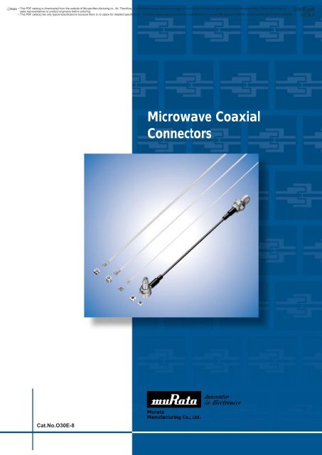
<strong>Microwave</strong> <strong>Coaxial</strong><br />
<strong>Connectors</strong><br />
Cat.No.O30E-8<br />
Murata<br />
Manufacturing Co., Ltd.
!Note • This !Note PDF catalog • Please is downloaded read rating and from !CAUTION the website (for of Murata storage, Manufacturing operating, rating, co., ltd. soldering, Therefore, mounting it’s specifications and handling) are in subject this catalog to change to prevent or our smoking products and/or in it may burning, be discontinued etc. without advance notice. Please check with our<br />
sales representatives • This catalog or product has only engineers typical specifications before ordering. because there is no space for detailed specifications. Therefore, please approve our product specifications or transact the approval sheet for product specifications before ordering.<br />
• This PDF catalog has only typical specifications because there is no space for detailed specifications. Therefore, please approve our product specifications or transact the approval sheet for product specifications before ordering.<br />
O30E.pdf<br />
07.9.3<br />
for EU RoHS Compliant<br />
• All the products on this catalog are complied with EU RoHS.<br />
• EU RoHS is "the European Directive 2002/95/EC on the Restriction of the Use<br />
of Certain Hazardous Substances in Electrical and Electronic Equipment".<br />
• For more details, please refer to our website 'Murata's Approach for EU RoHS'<br />
(http://www.murata.com/info/rohs.html).
!Note • This !Note PDF catalog • Please is downloaded read rating and from !CAUTION the website (for of Murata storage, Manufacturing operating, rating, co., ltd. soldering, Therefore, mounting it’s specifications and handling) are in subject this catalog to change to prevent or our smoking products and/or in it may burning, be discontinued etc. without advance notice. Please check with our<br />
sales representatives • This catalog or product has only engineers typical specifications before ordering. because there is no space for detailed specifications. Therefore, please approve our product specifications or transact the approval sheet for product specifications before ordering.<br />
• This PDF catalog has only typical specifications because there is no space for detailed specifications. Therefore, please approve our product specifications or transact the approval sheet for product specifications before ordering.<br />
CONTENTS<br />
O30E.pdf<br />
07.9.3<br />
1<br />
Part Numbering 2<br />
1<br />
<strong>Microwave</strong> <strong>Coaxial</strong> <strong>Connectors</strong> with Switch SWF <strong>Type</strong> 3<br />
2<br />
Notice 5<br />
2<br />
Package 8<br />
<strong>Microwave</strong> <strong>Coaxial</strong> <strong>Connectors</strong> with Switch SWD <strong>Type</strong> 9<br />
Notice 11<br />
3<br />
3<br />
Package 14<br />
Ultra Miniature <strong>SMT</strong> HSC <strong>Type</strong> 15<br />
Notice 18<br />
4<br />
4<br />
Package 21<br />
Miniature <strong>SMT</strong> GSC <strong>Type</strong> 22<br />
Notice 25<br />
5<br />
5<br />
Package 28<br />
<strong>SMT</strong> <strong>FSC</strong> <strong>Type</strong> 29<br />
Notice 32<br />
Package 35<br />
Miniaturized <strong>Microwave</strong> <strong>Coaxial</strong> Connector Cable List 36<br />
Recycled Paper
!Note • This !Note PDF catalog • Please is downloaded read rating and from !CAUTION the website (for of Murata storage, Manufacturing operating, rating, co., ltd. soldering, Therefore, mounting it’s specifications and handling) are in subject this catalog to change to prevent or our smoking products and/or in it may burning, be discontinued etc. without advance notice. Please check with our<br />
sales representatives • This catalog or product has only engineers typical specifications before ordering. because there is no space for detailed specifications. Therefore, please approve our product specifications or transact the approval sheet for product specifications before ordering.<br />
• This PDF catalog has only typical specifications because there is no space for detailed specifications. Therefore, please approve our product specifications or transact the approval sheet for product specifications before ordering.<br />
O30E.pdf<br />
07.9.3<br />
o Part Numbering<br />
<strong>Coaxial</strong> <strong>Connectors</strong> (Chip <strong>Type</strong> Receptacle)<br />
(Part Number)<br />
MM<br />
q<br />
7329<br />
w<br />
-27<br />
e<br />
00<br />
r<br />
R<br />
t<br />
A1<br />
y<br />
qProduct ID<br />
tPackage Product ID<br />
Product ID<br />
MM<br />
<strong>Microwave</strong> <strong>Coaxial</strong> <strong>Connectors</strong><br />
(Chip <strong>Type</strong> Receptacle)<br />
Code<br />
B<br />
R<br />
Package Product ID<br />
Bulk<br />
Reel<br />
wSeries<br />
Code<br />
Series<br />
4829<br />
HSC <strong>Type</strong><br />
7329<br />
<strong>FSC</strong> <strong>Type</strong><br />
8130<br />
SWF <strong>Type</strong><br />
8430<br />
SWD <strong>Type</strong><br />
9329<br />
GSC <strong>Type</strong><br />
eIndividual Specification Code (1)<br />
Code Individual Specification Code (1)<br />
-26<br />
Switch Connector SMD <strong>Type</strong><br />
-27<br />
Connector SMD <strong>Type</strong><br />
yPackage Detail<br />
Code<br />
Package Detail<br />
A1 <strong>FSC</strong>, SWD, GSC <strong>Type</strong> 1000pcs. /Reel (ø178mm)<br />
A4<br />
HSC <strong>Type</strong>, 4000pcs. /Reel (ø178mm)<br />
B0<br />
HSC <strong>Type</strong>, 10000pcs. /Reel (ø330mm)<br />
B3<br />
SWD <strong>Type</strong>, 3000pcs. /Reel (ø330mm)<br />
B4<br />
<strong>FSC</strong> <strong>Type</strong>, 4000pcs. /Reel (ø330mm)<br />
B5<br />
GSC <strong>Type</strong>, 5000pcs. /Reel (ø330mm)<br />
B8<br />
SWF <strong>Type</strong>, 8000pcs. /Reel (ø330mm)<br />
rIndividual Specification Code (2)<br />
Code Individual Specification Code (2)<br />
00<br />
Serial<br />
<strong>Coaxial</strong> <strong>Connectors</strong> (with Cable)<br />
(Part Number)<br />
MX<br />
q<br />
FG<br />
w<br />
76<br />
e<br />
r t y<br />
qProduct ID<br />
Product ID<br />
MX<br />
<strong>Coaxial</strong> <strong>Connectors</strong> (with Cable)<br />
wConnector (1)<br />
Code Connector (1)<br />
FG<br />
<strong>FSC</strong> <strong>Type</strong> for 76 Cable<br />
FK<br />
<strong>FSC</strong> <strong>Type</strong> for 81 Cable<br />
HP<br />
HSC <strong>Type</strong><br />
TK<br />
GSC <strong>Type</strong><br />
eCable<br />
Code<br />
Cable<br />
32<br />
0.4D, PFA, Single Shield Line, Spiral<br />
76<br />
0.8D, FEP, Single Shield Line<br />
81<br />
0.4D, FEP, Single Shield Line<br />
88 0.4D, PFA, Single Shield Line, Single Line<br />
92<br />
0.4D, PFA, Single Shield Line, Spiral<br />
rConnector (2)<br />
tLength<br />
Code Connector (2)<br />
FG<br />
<strong>FSC</strong> <strong>Type</strong> for 76 Cable<br />
FK<br />
<strong>FSC</strong> <strong>Type</strong> for 81 Cable<br />
HP<br />
HSC <strong>Type</strong><br />
TK<br />
GSC <strong>Type</strong><br />
XX<br />
None Connector<br />
Expressed by four figures. The unit is mm. From first to third<br />
figures are significant, and the fourth figure expresses the number<br />
of zeros which follow the three figures.<br />
Ex.)<br />
Code<br />
5000<br />
1001<br />
yIndividual Specification Code<br />
Expressed by two sign.<br />
Length<br />
500mm = 500 x 10 0<br />
1000mm = 100 x 10 1<br />
2
!Note • This !Note PDF catalog • Please is downloaded read rating and from !CAUTION the website (for of Murata storage, Manufacturing operating, rating, co., ltd. soldering, Therefore, mounting it’s specifications and handling) are in subject this catalog to change to prevent or our smoking products and/or in it may burning, be discontinued etc. without advance notice. Please check with our<br />
sales representatives • This catalog or product has only engineers typical specifications before ordering. because there is no space for detailed specifications. Therefore, please approve our product specifications or transact the approval sheet for product specifications before ordering.<br />
• This PDF catalog has only typical specifications because there is no space for detailed specifications. Therefore, please approve our product specifications or transact the approval sheet for product specifications before ordering.<br />
O30E.pdf<br />
07.9.3<br />
<strong>Microwave</strong> <strong>Coaxial</strong> <strong>Connectors</strong><br />
<strong>Microwave</strong> <strong>Coaxial</strong> <strong>Connectors</strong> with Switch SWF <strong>Type</strong><br />
1<br />
■ Features<br />
1. The coaxial connector with switch is very useful<br />
for characteristic measurement Cellular phone<br />
and microwave circuit.<br />
2. It is possible to switch the line connection and<br />
disconnection easily by special probe.<br />
3. Small size, low profile, size 2.5x2.5x1.4mm (LxWxH)<br />
4. Excellent characteristics, low IL 0.2dB max.<br />
V.S.W.R. 1.3 max. Isolation 15dB min. (DC to<br />
6GHz)<br />
5. Surface mountable and reflow solderable<br />
6. Tape package available<br />
MM8130-2600<br />
C Terminal<br />
Side<br />
2.5±0.2<br />
1.4±0.1<br />
2.5±0.2<br />
Dia. 2.1±0.2<br />
0.8±0.2<br />
R Terminal<br />
Side<br />
IN<br />
OUT<br />
GROUND<br />
(in mm)<br />
■ Applications<br />
Cellular phone, W-LAN, Other wireless and measurement<br />
equipment<br />
Part Number<br />
Rated<br />
Voltage<br />
(Vrms)<br />
Contact<br />
Resistance<br />
(max.) (ohm)<br />
Withstand<br />
Voltage<br />
(Vrms)<br />
Insulation Durability<br />
Resistance<br />
(M ohm) (cycles)<br />
Frequency<br />
Rating<br />
Temperature<br />
Range<br />
(degree C)<br />
MM8130-2600 250 0.07 300 (AC) 500 100 to 6GHz -40 to +85<br />
VSWR<br />
Insertion<br />
Loss (On)<br />
(dB)<br />
1.2 max. 0.1 max.<br />
(DC to 3GHz) (DC to 3GHz)<br />
Isolation (Off)<br />
(dB)<br />
20 min.<br />
(DC to 3GHz)<br />
Inner<br />
Electrode (C)<br />
Stainless Steel<br />
Gold plated<br />
Inner<br />
Electrode (R)<br />
(material)<br />
Outer<br />
Electrode<br />
(material)<br />
Stainless Steel Copper Alloy<br />
Gold plated Gold plated<br />
Impedance: 50ohm<br />
■ Measurement Probe Dimensions<br />
MM126036<br />
MXHS83QE3000<br />
2-Dia. 2.6±0.15<br />
Dia. 19.68±0.2<br />
Dia. 10±0.2<br />
SMA-J<br />
Dia. 3.8±0.1<br />
Dia. 5.4±0.1<br />
(7.1)<br />
(32)<br />
300±4<br />
(26)<br />
16±0.15<br />
9±0.2<br />
(4.02)<br />
Dia. 7±0.1<br />
15.2±0.2<br />
9±0.2<br />
3.1±0.1<br />
0.8D Cable<br />
SMA-J<br />
(13.35)<br />
11.85±0.2 21.65±0.3<br />
(33.5)<br />
Dia. 3.2±0.1<br />
Dia. 4.3±0.1<br />
Dia. 5.8±0.2<br />
(in mm)<br />
(in mm)<br />
Continued on the following page.<br />
3
!Note • This !Note PDF catalog • Please is downloaded read rating and from !CAUTION the website (for of Murata storage, Manufacturing operating, rating, co., ltd. soldering, Therefore, mounting it’s specifications and handling) are in subject this catalog to change to prevent or our smoking products and/or in it may burning, be discontinued etc. without advance notice. Please check with our<br />
sales representatives • This catalog or product has only engineers typical specifications before ordering. because there is no space for detailed specifications. Therefore, please approve our product specifications or transact the approval sheet for product specifications before ordering.<br />
• This PDF catalog has only typical specifications because there is no space for detailed specifications. Therefore, please approve our product specifications or transact the approval sheet for product specifications before ordering.<br />
1<br />
Continued from the preceding page.<br />
■ Measurement Probe Dimensions<br />
■ Structure<br />
MXHS83QH3000<br />
O30E.pdf<br />
07.9.3<br />
300±4<br />
(32) (26)<br />
Probe<br />
20.1±0.2<br />
13.9±0.2<br />
12±0.2<br />
3.1±0.1<br />
0.8D Cable<br />
SMA-J<br />
Dia. 3.2±0.1<br />
Dia. 3.4±0.1<br />
Dia. 4.3±0.1<br />
Dia. 5.8±0.2<br />
(in mm)<br />
OUT<br />
Without Probe<br />
IN<br />
OUT<br />
With Probe<br />
IN<br />
■ Standard Land Dimensions<br />
1. Standard Pattern Dimensions<br />
I/O pattern should be designed to match 50 ohm impedance<br />
circuit.<br />
Typical PCB material is glass epoxy (εr=4.8). Thickness is<br />
1.0mm.<br />
The solder resist should be printed except for the land<br />
pattern on the PCB.<br />
4<br />
2.8<br />
1.3<br />
0.5<br />
3.44<br />
2.7<br />
1.1<br />
1.74<br />
2.9<br />
4.14<br />
0.5 1.74 0.5<br />
Land<br />
Electrode<br />
(in mm)<br />
2. Standard Solder Stencil Mask Pattern<br />
Follow standard solder stencil mask pattern to avoid the<br />
possibility of solder being trapped under connector.<br />
0.28<br />
2.7<br />
1.1<br />
2.14<br />
2.7<br />
1.3<br />
2.48<br />
Standard Solder Stencil Mask Pattern<br />
(Mask thickness 0.12mm)<br />
(in mm)<br />
4
!Note • This !Note PDF catalog • Please is downloaded read rating and from !CAUTION the website (for of Murata storage, Manufacturing operating, rating, co., ltd. soldering, Therefore, mounting it’s specifications and handling) are in subject this catalog to change to prevent or our smoking products and/or in it may burning, be discontinued etc. without advance notice. Please check with our<br />
sales representatives • This catalog or product has only engineers typical specifications before ordering. because there is no space for detailed specifications. Therefore, please approve our product specifications or transact the approval sheet for product specifications before ordering.<br />
• This PDF catalog has only typical specifications because there is no space for detailed specifications. Therefore, please approve our product specifications or transact the approval sheet for product specifications before ordering.<br />
O30E.pdf<br />
07.9.3<br />
Notice<br />
1<br />
■ Notice (Storage and Operating Condition)<br />
1. Environment Conditions<br />
(1) This product is designed for use in electrical<br />
equipment in the environment (temperature,<br />
humidity, atmospheric pressure, etc.)<br />
specified in this approval drawing. It may not<br />
be used in the following environments or under<br />
the following conditions:<br />
(a) Ambient air containing corrosive gas<br />
(Chlorine gas, Hydrogen sulfide gas,<br />
Ammonia gas, Sulfuric acid gas, Nitric<br />
oxide gas, etc.)<br />
(b) Ambient air containing volatile or<br />
combustible gas<br />
(c) In liquid (water, oil, chemical solution,<br />
organic solvents, etc.)<br />
(d) In environments with a high concentration of<br />
airborne particles<br />
(e) In direct sunlight<br />
(f) Dusty conditions<br />
(g) In freezing<br />
(h) Other environments similar to the above<br />
conditions<br />
(2) Contact the manufacturer before using the<br />
product in any of the above environments or<br />
under any of the above conditions.<br />
2. Storage<br />
Store in manufacturer's package or tightly<br />
re-closed box with the following conditions. Use<br />
this product within 6 months after receipt. Check<br />
the terminal solderability before use if the<br />
product has been stored for more than 6 months.<br />
Temperature: -10 to +40 degree C<br />
Humidity: 15 to 85% RH<br />
5
!Note • This !Note PDF catalog • Please is downloaded read rating and from !CAUTION the website (for of Murata storage, Manufacturing operating, rating, co., ltd. soldering, Therefore, mounting it’s specifications and handling) are in subject this catalog to change to prevent or our smoking products and/or in it may burning, be discontinued etc. without advance notice. Please check with our<br />
sales representatives • This catalog or product has only engineers typical specifications before ordering. because there is no space for detailed specifications. Therefore, please approve our product specifications or transact the approval sheet for product specifications before ordering.<br />
• This PDF catalog has only typical specifications because there is no space for detailed specifications. Therefore, please approve our product specifications or transact the approval sheet for product specifications before ordering.<br />
O30E.pdf<br />
07.9.3<br />
1<br />
Notice<br />
■ Notice (Soldering and Mounting)<br />
1. Reflow soldering<br />
Soldering must be carried out without exceeding the<br />
allowable soldering temperature and time shown within<br />
the shaded area of Figure "Allowable Temperature and<br />
Time of Reflow Soldering".<br />
In case the soldering is repeated, the maximum time in<br />
Figure "Allowable Temperature and Time of Reflow<br />
Soldering" should be accumulated time. The standard<br />
soldering conditions are shown in Figure "Reflow<br />
Soldering Standard Conditions".<br />
Follow standard solder stencil mask pattern to avoid the<br />
possibility of solder being trapped under connector.<br />
2. Soldering by soldering iron<br />
Soldering by soldering iron should be carried out in<br />
accordance to the following conditions.<br />
Pre-heating Temperature 150D<br />
Time 60 to 120 s.<br />
Soldering Temperature (at the tip of the soldering<br />
iron) less than 350D<br />
Time less than 3 s.<br />
3. We cannot warrant against mishaps caused by any use<br />
of this product that deviates from allowable temperature<br />
and time of reflow soldering.<br />
4. In soldering, do not apply excessive mechanical force to<br />
terminals or leads greater than specified in the drawing.<br />
Allowable Temperature and Time of Reflow Soldering<br />
260<br />
250<br />
240<br />
230<br />
220<br />
210<br />
200<br />
190<br />
180<br />
Reflow Soldering Standard Conditions<br />
Temperature (D)<br />
Temperature (D)<br />
240<br />
230<br />
150<br />
100<br />
25<br />
0<br />
30 60 90 120 150 180 210 240<br />
Time (sec.) Solder: Sn-3.0Ag-0.5Cu<br />
Pre-heating 150±20D<br />
60-120 sec.<br />
Peak temperature 250±5D<br />
30-50 sec.<br />
Time (sec.)<br />
30 sec. max.<br />
Measuring point of temperature: In-Out Terminals of the Device<br />
Reflow Soldering: Both Convection and Infrared Rays<br />
: Hot Air<br />
: Hot Plate<br />
5. Please note the following in case of soldering terminals<br />
or leads of the product.<br />
(1) Use Rosin based flux, but not with strong acid flux<br />
(Chlorine content should be less than 0.20wt%).<br />
(2) Flux should be thoroughly cleaned from connector to<br />
prevent possible deterioration of electrical<br />
characteristics.<br />
6. Please mount this product at the position so that stress<br />
by wrap and/or bend of the PCB may not apply to it.<br />
7. Please avoid the cleaning of this product.<br />
Continued on the following page.<br />
6
!Note • This !Note PDF catalog • Please is downloaded read rating and from !CAUTION the website (for of Murata storage, Manufacturing operating, rating, co., ltd. soldering, Therefore, mounting it’s specifications and handling) are in subject this catalog to change to prevent or our smoking products and/or in it may burning, be discontinued etc. without advance notice. Please check with our<br />
sales representatives • This catalog or product has only engineers typical specifications before ordering. because there is no space for detailed specifications. Therefore, please approve our product specifications or transact the approval sheet for product specifications before ordering.<br />
• This PDF catalog has only typical specifications because there is no space for detailed specifications. Therefore, please approve our product specifications or transact the approval sheet for product specifications before ordering.<br />
O30E.pdf<br />
07.9.3<br />
Notice<br />
1<br />
Continued from the preceding page.<br />
■ Notice(Handling)<br />
1. Automatic Measurement Probe (MM126036)<br />
Automatic measurement probe (MM126036) should be<br />
used on the condition in Fig. 1 for good connection<br />
without any damages.<br />
The engagement strokes from the flange to the tip of<br />
probe is 18.28mm to 19.78mm with vertical (0+/-2 degree)<br />
direction.<br />
Fig. 1<br />
Insertion the Automatic Measurement Probe<br />
(MM126036) in Receptacle (MM8130-2600)<br />
0±2°<br />
18.28(Minimum Point for Using)<br />
19.78(Maximum Point for Using)<br />
1.5 (Using Range)<br />
(in mm)<br />
2. L <strong>Type</strong> Probe with Locking Function<br />
(MXHS83QE3000, MXHS83QH3000)<br />
Do not try to pull the cable, when a connector with a<br />
coaxial cable is handled.<br />
Do not give a twisted torque to the cable and connector.<br />
Mechanical stress:<br />
The stress to the connector should be limited as figure<br />
shown right.<br />
(1) Stress to the housing.<br />
Stress A and B: 0.5N max.<br />
(2) Stress to the outer sleeve.<br />
Stress C: 0.6N max.<br />
Stress D: 0.6N max.<br />
(3) Cable pull strength.<br />
Stress E: 0.5N max.<br />
A<br />
Mechanical Stress after Engagement<br />
C<br />
B<br />
D<br />
MM8130-2600<br />
PCB<br />
E<br />
3. Usage Condition<br />
(1) Do not apply electrical voltage greater than specified<br />
in the catalog. It might cause degradation or<br />
destruction of the product. Even if it endures during a<br />
short time, long time qualification is not guaranteed.<br />
(2) Confirm that product perfomance is not influenced<br />
with any other components or materials which<br />
directly contact products.<br />
4. Handling<br />
Do not apply excessive shock or load to subassembly<br />
products such as soldered printed circuit board in case<br />
handling or transporting.<br />
7
!Note • This !Note PDF catalog • Please is downloaded read rating and from !CAUTION the website (for of Murata storage, Manufacturing operating, rating, co., ltd. soldering, Therefore, mounting it’s specifications and handling) are in subject this catalog to change to prevent or our smoking products and/or in it may burning, be discontinued etc. without advance notice. Please check with our<br />
sales representatives • This catalog or product has only engineers typical specifications before ordering. because there is no space for detailed specifications. Therefore, please approve our product specifications or transact the approval sheet for product specifications before ordering.<br />
• This PDF catalog has only typical specifications because there is no space for detailed specifications. Therefore, please approve our product specifications or transact the approval sheet for product specifications before ordering.<br />
O30E.pdf<br />
07.9.3<br />
1<br />
Package<br />
■ Dimensions of Reel<br />
■ Dimensions of Taping<br />
P2<br />
P0<br />
D0<br />
T<br />
E<br />
A<br />
D<br />
C<br />
B<br />
N<br />
W1<br />
W<br />
F<br />
5° max. 5° max.<br />
B<br />
P1<br />
A<br />
K<br />
W2<br />
Part Number<br />
MM8130-2600RB8<br />
Tolerance<br />
A<br />
330<br />
±2.0<br />
B<br />
13<br />
±0.5<br />
C<br />
21<br />
±0.8<br />
D<br />
2<br />
±0.5<br />
N (min.)<br />
Dia. 100<br />
±1.0<br />
W1<br />
9.4<br />
±1.0<br />
W2 (max.)<br />
13.4<br />
±1.0<br />
(in mm)<br />
A<br />
2.8±0.1<br />
P0<br />
4±0.1<br />
B<br />
2.8±0.1<br />
P1<br />
4±0.1<br />
W<br />
8±0.2<br />
P2<br />
2±0.1<br />
D0<br />
Dia.1.5+0.1<br />
E<br />
1.75±0.1<br />
F<br />
3.5±0.1<br />
K<br />
1.6±0.1<br />
T<br />
0.25±0.05 (in mm)<br />
■ Minimum Quantity<br />
MM8130-2600RB8: 330 mm dia.reel/8000 pcs.<br />
MM8130-2600B: Bulk/free<br />
8
!Note • This !Note PDF catalog • Please is downloaded read rating and from !CAUTION the website (for of Murata storage, Manufacturing operating, rating, co., ltd. soldering, Therefore, mounting it’s specifications and handling) are in subject this catalog to change to prevent or our smoking products and/or in it may burning, be discontinued etc. without advance notice. Please check with our<br />
sales representatives • This catalog or product has only engineers typical specifications before ordering. because there is no space for detailed specifications. Therefore, please approve our product specifications or transact the approval sheet for product specifications before ordering.<br />
• This PDF catalog has only typical specifications because there is no space for detailed specifications. Therefore, please approve our product specifications or transact the approval sheet for product specifications before ordering.<br />
O30E.pdf<br />
07.9.3<br />
<strong>Microwave</strong> <strong>Coaxial</strong> <strong>Connectors</strong><br />
<strong>Microwave</strong> <strong>Coaxial</strong> <strong>Connectors</strong> with Switch SWD <strong>Type</strong><br />
■ Features<br />
1. The coaxial connector with switch is very useful<br />
for characteristic measurement of hand held phone<br />
and microwave circuit.<br />
2. It is possible to switch the line connection and<br />
disconnection easily by special probe.<br />
3. Small size, low profile, size 3x3x1.75mm (LxWxH)<br />
4. Excellent characteristics, low IL 0.2dB max.<br />
V.S.W.R. 1.3 max. Isolation 15dB min. (DC to<br />
6GHz)<br />
5. Surface mountable and reflow solderable<br />
6. Tape package available<br />
MM8430-2610<br />
C Terminal<br />
Side<br />
3±0.1<br />
1.75±0.15<br />
A<br />
3±0.1<br />
B<br />
B<br />
dia 2.1±0.2<br />
R Terminal<br />
Side<br />
A<br />
0.8±0.2<br />
IN<br />
OUT<br />
GROUND<br />
(in mm)<br />
2<br />
■ Applications<br />
Cellular phone, W-LAN, Other wireless and measurement<br />
equipment<br />
Part Number<br />
Rated<br />
Voltage<br />
(Vrms)<br />
Contact<br />
Resistance<br />
(max.) (ohm)<br />
Withstand<br />
Voltage<br />
(Vrms)<br />
Insulation Durability<br />
Resistance<br />
(M ohm) (cycles)<br />
Frequency<br />
Rating<br />
Temperature<br />
Range<br />
(degree C)<br />
MM8430-2610 250 0.05 300 (AC) 500 500 to 6GHz -40 to +85<br />
Impedance: 50ohm<br />
VSWR<br />
Insertion<br />
Loss (On)<br />
(dB)<br />
1.2 max. 0.1 max.<br />
(DC to 3GHz) (DC to 3GHz)<br />
Isolation (Off)<br />
(dB)<br />
20 min.<br />
(DC to 3GHz)<br />
Inner<br />
Electrode (C)<br />
Stainless Steel<br />
Gold plated<br />
Inner<br />
Electrode (R)<br />
(material)<br />
Copper Alloy<br />
Gold plated<br />
Outer<br />
Electrode<br />
(material)<br />
Copper Alloy<br />
Silver plated<br />
■ Measurement Probe Dimensions<br />
MM126036<br />
MXHS83QE3000<br />
2-Dia. 2.6±0.15<br />
Dia. 19.68±0.2<br />
Dia. 10±0.2<br />
SMA-J<br />
Dia. 3.8±0.1<br />
Dia. 5.4±0.1<br />
(7.1)<br />
(32)<br />
300±4<br />
(26)<br />
16±0.15<br />
9±0.2<br />
(4.02)<br />
Dia. 7±0.1<br />
15.2±0.2<br />
9±0.2<br />
3.1±0.1<br />
0.8D Cable<br />
SMA-J<br />
(13.35)<br />
11.85±0.2 21.65±0.3<br />
(33.5)<br />
Dia. 3.2±0.1<br />
Dia. 4.3±0.1<br />
Dia. 5.8±0.2<br />
(in mm)<br />
(in mm)<br />
Continued on the following page.<br />
9
!Note • This !Note PDF catalog • Please is downloaded read rating and from !CAUTION the website (for of Murata storage, Manufacturing operating, rating, co., ltd. soldering, Therefore, mounting it’s specifications and handling) are in subject this catalog to change to prevent or our smoking products and/or in it may burning, be discontinued etc. without advance notice. Please check with our<br />
sales representatives • This catalog or product has only engineers typical specifications before ordering. because there is no space for detailed specifications. Therefore, please approve our product specifications or transact the approval sheet for product specifications before ordering.<br />
• This PDF catalog has only typical specifications because there is no space for detailed specifications. Therefore, please approve our product specifications or transact the approval sheet for product specifications before ordering.<br />
Continued from the preceding page.<br />
■ Measurement Probe Dimensions<br />
■ Structure<br />
MXHS83QH3000<br />
O30E.pdf<br />
07.9.3<br />
300±4<br />
(32) (26)<br />
Probe<br />
2<br />
20.1±0.2<br />
13.9±0.2<br />
12±0.2<br />
3.1±0.1<br />
0.8D Cable<br />
SMA-J<br />
Dia. 3.2±0.1<br />
Dia. 3.4±0.1<br />
Dia. 4.3±0.1<br />
Dia. 5.8±0.2<br />
(in mm)<br />
OUT<br />
Without Probe<br />
IN<br />
OUT<br />
With Probe<br />
IN<br />
■ Standard Land Dimensions<br />
1. Standard pattern dimensions<br />
I/O pattern should be designed to match 50 ohm impedance<br />
circuit.<br />
Typical PCB material is glass epoxy (εr=4.8). Thickness is<br />
1.0mm.<br />
The solder resist should be printed except for the land<br />
pattern on the PCB.<br />
4<br />
2<br />
1<br />
0.5<br />
Through hole<br />
3<br />
1<br />
1<br />
2.1<br />
3.1<br />
4.1<br />
Land<br />
Electrode<br />
(1.5)<br />
(1.5)<br />
1.74<br />
(in mm)<br />
2. Standard solder stencil mask pattern<br />
Follow Standard solder stencil mask pattern to avoid the<br />
possibility of solder being trapped under connector.<br />
0.5<br />
3.5<br />
2.3<br />
1<br />
3<br />
2<br />
3.5<br />
The Standard solder stencil mask pattern<br />
(Mask thickness 0.15mm)<br />
(in mm)<br />
10
!Note • This !Note PDF catalog • Please is downloaded read rating and from !CAUTION the website (for of Murata storage, Manufacturing operating, rating, co., ltd. soldering, Therefore, mounting it’s specifications and handling) are in subject this catalog to change to prevent or our smoking products and/or in it may burning, be discontinued etc. without advance notice. Please check with our<br />
sales representatives • This catalog or product has only engineers typical specifications before ordering. because there is no space for detailed specifications. Therefore, please approve our product specifications or transact the approval sheet for product specifications before ordering.<br />
• This PDF catalog has only typical specifications because there is no space for detailed specifications. Therefore, please approve our product specifications or transact the approval sheet for product specifications before ordering.<br />
O30E.pdf<br />
07.9.3<br />
Notice<br />
■ Notice (Storage and Operating Condition)<br />
1. Environment Conditions<br />
(1) This product is designed for use in electrical<br />
equipment in the environment (temperature,<br />
humidity, atmospheric pressure, etc.)<br />
specified in this approval drawing. It may not<br />
be used in the following environments or under<br />
the following conditions:<br />
(a) Ambient air containing corrosive gas<br />
(Chlorine gas, Hydrogen sulfide gas,<br />
Ammonia gas, Sulfuric acid gas, Nitric<br />
oxide gas, etc.)<br />
(b) Ambient air containing volatile or<br />
combustible gas<br />
(c) In liquid (water, oil, chemical solution,<br />
organic solvents, etc.)<br />
(d) In environments with a high concentration of<br />
airborne particles<br />
(e) In direct sunlight<br />
(f) Dusty conditions<br />
(g) In freezing<br />
(h) Other environments similar to the above<br />
conditions<br />
(2) Contact the manufacturer before using the<br />
product in any of the above environments or<br />
under any of the above conditions.<br />
2. Storage<br />
Store in manufacturer's package or tightly<br />
re-closed box with the following conditions. Use<br />
this product within 6 months after receipt. Check<br />
the terminal solderability before use if the<br />
product has been stored for more than 6 months.<br />
Temperature: -10 to +40 degree C<br />
Humidity: 15 to 85% RH<br />
2<br />
11
!Note • This !Note PDF catalog • Please is downloaded read rating and from !CAUTION the website (for of Murata storage, Manufacturing operating, rating, co., ltd. soldering, Therefore, mounting it’s specifications and handling) are in subject this catalog to change to prevent or our smoking products and/or in it may burning, be discontinued etc. without advance notice. Please check with our<br />
sales representatives • This catalog or product has only engineers typical specifications before ordering. because there is no space for detailed specifications. Therefore, please approve our product specifications or transact the approval sheet for product specifications before ordering.<br />
• This PDF catalog has only typical specifications because there is no space for detailed specifications. Therefore, please approve our product specifications or transact the approval sheet for product specifications before ordering.<br />
O30E.pdf<br />
07.9.3<br />
Notice<br />
2<br />
■ Notice (Soldering and Mounting)<br />
1. Reflow soldering<br />
Soldering must be carried out without exceeding the<br />
allowable soldering temperature and time shown within<br />
the shaded area of Figure "Allowable Temperature and<br />
Time of Reflow Soldering".<br />
In case the soldering is repeated, the maximum time in<br />
Figure "Allowable Temperature and Time of Reflow<br />
Soldering" should be accumulated time. The standard<br />
soldering conditions are shown in Figure "Reflow<br />
Soldering Standard Conditions".<br />
Follow standard solder stencil mask pattern to avoid the<br />
possibility of solder being trapped under connector.<br />
2. Soldering by soldering iron<br />
Soldering by soldering iron should be carried out in<br />
accordance to the following conditions.<br />
Pre-heating Temperature 150D<br />
Time 60 to 120 s.<br />
Soldering Temperature (at the tip of the soldering<br />
iron) less than 350D<br />
Time less than 3 s.<br />
3. We cannot warrant against mishaps caused by any use<br />
of this product that deviates from allowable temperature<br />
and time of reflow soldering.<br />
4. In soldering, do not apply excessive mechanical force to<br />
terminals or leads greater than specified in the drawing.<br />
Allowable Temperature and Time of Reflow Soldering<br />
260<br />
250<br />
240<br />
230<br />
220<br />
210<br />
200<br />
190<br />
180<br />
Reflow Soldering Standard Conditions<br />
Temperature (D)<br />
Temperature (D)<br />
240<br />
230<br />
150<br />
100<br />
25<br />
0<br />
30 60 90 120 150 180 210 240<br />
Time (sec.) Solder: Sn-3.0Ag-0.5Cu<br />
Pre-heating 150±20D<br />
60-120 sec.<br />
Peak temperature 250±5D<br />
30-50 sec.<br />
Time (sec.)<br />
30 sec. max.<br />
Measuring point of temperature: In-Out Terminals of the Device<br />
Reflow Soldering: Both Convection and Infrared Rays<br />
: Hot Air<br />
: Hot Plate<br />
5. Please note the following in case of soldering terminals<br />
or leads of the product.<br />
(1) Use Rosin based flux, but not with strong acid flux<br />
(Chlorine content should be less than 0.20wt%).<br />
(2) Flux should be thoroughly cleaned from connector to<br />
prevent possible deterioration of electrical<br />
characteristics.<br />
6. Please mount this product at the position so that stress<br />
by wrap and/or bend of the PCB may not apply to it.<br />
7. Please avoid the cleaning of this product.<br />
Continued on the following page.<br />
12
!Note • This !Note PDF catalog • Please is downloaded read rating and from !CAUTION the website (for of Murata storage, Manufacturing operating, rating, co., ltd. soldering, Therefore, mounting it’s specifications and handling) are in subject this catalog to change to prevent or our smoking products and/or in it may burning, be discontinued etc. without advance notice. Please check with our<br />
sales representatives • This catalog or product has only engineers typical specifications before ordering. because there is no space for detailed specifications. Therefore, please approve our product specifications or transact the approval sheet for product specifications before ordering.<br />
• This PDF catalog has only typical specifications because there is no space for detailed specifications. Therefore, please approve our product specifications or transact the approval sheet for product specifications before ordering.<br />
O30E.pdf<br />
07.9.3<br />
Notice<br />
Continued from the preceding page.<br />
Notice (Handling)<br />
1. Automatic Measurement Probe (MM126036)<br />
Automatic measurement probe (MM126036) should be<br />
used under conditions in Fig. 1 for good connection<br />
without any damages.<br />
The engagement strokes from the flange to the tip of<br />
probe is 18.28mm to 19.78mm with vertical (0±2°)<br />
direction.<br />
Fig. 1<br />
Insertion the Automatic Measurement Probe<br />
(MM126036) in Receptacle (MM8430-2610)<br />
0±2°<br />
2<br />
18.28(Minimum Point for Using)<br />
19.78(Maximum Point for Using)<br />
1.5 (Using Range)<br />
2. L <strong>Type</strong> Probe with Locking Function<br />
(MXHS83QE3000, MXHS83QH3000)<br />
Avoid pulling cable when probe is locked into connector.<br />
Avoid twisting probe or cable when engaging or<br />
disengaging from connector.<br />
Mechanical stress:<br />
The stress to the connector should be limited as figure<br />
shown right.<br />
(1) Stress to the housing.<br />
Stress A and B: 0.5N max.<br />
(2) Stress to the outer sleeve.<br />
Stress C: 0.6N max.<br />
Stress D: 0.6N max.<br />
(3) Cable pull strength.<br />
Stress E: 0.5N max.<br />
A<br />
Mechanical stress after engagement<br />
C<br />
B<br />
D<br />
MM8430-2610<br />
PCB<br />
E<br />
3. Usage Condition<br />
(1) Do not apply electrical voltage greater than specified<br />
in the catalog. It might cause degradation or<br />
destruction of the product. Even if it endures during a<br />
short time, long time qualification is not guaranteed.<br />
(2) Confirm that product performance is not influenced<br />
with any other components or materials which<br />
directly contact products.<br />
4. Handling<br />
Avoid excessive stress when handling and transporting<br />
printed circuit board after connector and/or assembly<br />
has been secured to PCB.<br />
13
!Note • This !Note PDF catalog • Please is downloaded read rating and from !CAUTION the website (for of Murata storage, Manufacturing operating, rating, co., ltd. soldering, Therefore, mounting it’s specifications and handling) are in subject this catalog to change to prevent or our smoking products and/or in it may burning, be discontinued etc. without advance notice. Please check with our<br />
sales representatives • This catalog or product has only engineers typical specifications before ordering. because there is no space for detailed specifications. Therefore, please approve our product specifications or transact the approval sheet for product specifications before ordering.<br />
• This PDF catalog has only typical specifications because there is no space for detailed specifications. Therefore, please approve our product specifications or transact the approval sheet for product specifications before ordering.<br />
O30E.pdf<br />
07.9.3<br />
Package<br />
■ Dimensions of Reel<br />
■ Dimensions of Taping<br />
P2 P0 D0 T<br />
E<br />
2<br />
D<br />
B<br />
W1<br />
F<br />
3 degree Max.<br />
A<br />
C<br />
N<br />
W<br />
3 degree Max.<br />
B<br />
P1 A K<br />
W2<br />
(in mm)<br />
Murata Part Number<br />
MM8430-2610RA1<br />
MM8430-2610RB3<br />
TOLERANCE<br />
A<br />
178<br />
330<br />
±2.0<br />
B<br />
13<br />
13<br />
±0.5<br />
C<br />
21<br />
21<br />
±0.8<br />
D<br />
2<br />
2<br />
±0.5<br />
N (min.)<br />
Dia. 50<br />
Dia. 50<br />
–<br />
W1<br />
13.5<br />
13.5<br />
±1.5<br />
(in mm)<br />
W2 (max.)<br />
18.5<br />
18.5<br />
–<br />
A<br />
3.4±0.1<br />
P0<br />
4±0.1<br />
B<br />
3.4±0.1<br />
P1<br />
8±0.1<br />
W<br />
12±0.2<br />
P2<br />
2±0.1<br />
D0<br />
Dia.1.5+0.1<br />
T<br />
0.3±0.05<br />
E<br />
1.75±0.1<br />
F<br />
5.5±0.1<br />
K<br />
2.0±0.15<br />
■ Minimum Quantity<br />
MM8430-2610RA1: dia.180 mm reel/1000 pcs.<br />
MM8430-2610RB3: dia.330 mm reel/3000 pcs.<br />
MM8430-2610B: Bulk/free<br />
14
!Note • This !Note PDF catalog • Please is downloaded read rating and from !CAUTION the website (for of Murata storage, Manufacturing operating, rating, co., ltd. soldering, Therefore, mounting it’s specifications and handling) are in subject this catalog to change to prevent or our smoking products and/or in it may burning, be discontinued etc. without advance notice. Please check with our<br />
sales representatives • This catalog or product has only engineers typical specifications before ordering. because there is no space for detailed specifications. Therefore, please approve our product specifications or transact the approval sheet for product specifications before ordering.<br />
• This PDF catalog has only typical specifications because there is no space for detailed specifications. Therefore, please approve our product specifications or transact the approval sheet for product specifications before ordering.<br />
O30E.pdf<br />
07.9.3<br />
<strong>Microwave</strong> <strong>Coaxial</strong> <strong>Connectors</strong><br />
Ultra Miniature <strong>SMT</strong> HSC <strong>Type</strong><br />
■ Features<br />
1. The mating height is only 1.2mm maximum by new<br />
mechanical design. Suitable for low profile design.<br />
2. New mating mechanical desigh makes stable feeling<br />
connection.<br />
3. Soft and ultra thin 0.81mm diameter flexible coaxial<br />
cables is available.<br />
4. High performance with wide frequency range(DC to<br />
6GHz). VSWR at 3GHz to 6GHz is 1.45 maximum.<br />
MXHP<br />
2.06<br />
0.85<br />
(2.1 dia.)<br />
2.34±0.5<br />
3<br />
■ Applications<br />
Portable telephone, cordless telephone(analog and<br />
digital), GPS, and other microwave radio and<br />
measurement equipment.<br />
0.8 Dia.<br />
0.7<br />
(in mm)<br />
0.4<br />
2<br />
1.4<br />
2<br />
1.5 Dia.<br />
0.5<br />
1.52<br />
MM4829-2702<br />
0.6<br />
Hot Terminal<br />
Ground Terminal<br />
Tolerances Unless<br />
Otherwise Specified: ±0.2<br />
(in mm)<br />
Part Number<br />
Rated<br />
Voltage<br />
(V)<br />
Contact<br />
Resistance (max.)<br />
(ohm)<br />
Withstanding<br />
Voltage<br />
(rms)<br />
Insulation<br />
Resistance (min.)<br />
(M ohm)<br />
Durability<br />
(cycles)<br />
Frequency<br />
Rating<br />
(GHz)<br />
Temperature<br />
Range<br />
(degree C)<br />
MM4829-2702 250 0.020 300 (AC) 500 30 to 6.0 -40 to +85<br />
Impedance: 50ohm<br />
VSWR Center Contact Outer Contact Insulator<br />
1.3 max.<br />
(DC to 3GHz)<br />
Copper Alloy<br />
Gold plated<br />
Copper Alloy<br />
Silver plated<br />
Engineering plastic<br />
■ Measurement Adapter Dimensions (for Receptacle)<br />
MM121490 (Hand measurement)<br />
13.3±0.15<br />
HSC-Female<br />
SMA-J<br />
2±0.1<br />
(4.3)<br />
Dia. 5.33±0.2<br />
Dia. 2.5±0.1<br />
Dia. 5.33±0.1<br />
Dia. 3.0±0.1<br />
SMA-J<br />
MM121491 (Automatic measurement)<br />
17.96±0.2<br />
2±0.2 7.91±0.1<br />
5.65±0.1<br />
HSC-CONTACT<br />
Dia. 5.33±0.2<br />
Dia. 3±0.1<br />
Dia. 5.33±0.1<br />
Dia. 6.5±0.2<br />
(in mm)<br />
15
!Note • This !Note PDF catalog • Please is downloaded read rating and from !CAUTION the website (for of Murata storage, Manufacturing operating, rating, co., ltd. soldering, Therefore, mounting it’s specifications and handling) are in subject this catalog to change to prevent or our smoking products and/or in it may burning, be discontinued etc. without advance notice. Please check with our<br />
sales representatives • This catalog or product has only engineers typical specifications before ordering. because there is no space for detailed specifications. Therefore, please approve our product specifications or transact the approval sheet for product specifications before ordering.<br />
• This PDF catalog has only typical specifications because there is no space for detailed specifications. Therefore, please approve our product specifications or transact the approval sheet for product specifications before ordering.<br />
O30E.pdf<br />
07.9.3<br />
■ Measurement Adapter Dimensions (for Cable Assembly)<br />
■ Cable Length Tolerance<br />
MM121500 (Hand measurement)<br />
12.95±0.2<br />
HSC-Male<br />
8.55±0.4 0.4±0.05<br />
L<br />
SMA-J<br />
Dia. 5.33±0.2<br />
Dia. 1.5±0.02<br />
Cable Length L (mm)<br />
Over Less than<br />
20<br />
100<br />
100<br />
500<br />
500<br />
1000<br />
Dimensional<br />
Tolerance (mm)<br />
±3<br />
±4<br />
±10<br />
1000<br />
–<br />
+2% of L<br />
–0% of L<br />
3<br />
(in mm)<br />
■ Disengagement Tool (Part Number: M19100)<br />
■ Profile Dimensions<br />
6.0 45<br />
35 3<br />
2.9<br />
1.85 max.<br />
5<br />
Dia. 2.7<br />
HSC<br />
(in mm)<br />
1.2 max.<br />
(in mm)<br />
Continued on the following page.<br />
16
!Note • This !Note PDF catalog • Please is downloaded read rating and from !CAUTION the website (for of Murata storage, Manufacturing operating, rating, co., ltd. soldering, Therefore, mounting it’s specifications and handling) are in subject this catalog to change to prevent or our smoking products and/or in it may burning, be discontinued etc. without advance notice. Please check with our<br />
sales representatives • This catalog or product has only engineers typical specifications before ordering. because there is no space for detailed specifications. Therefore, please approve our product specifications or transact the approval sheet for product specifications before ordering.<br />
• This PDF catalog has only typical specifications because there is no space for detailed specifications. Therefore, please approve our product specifications or transact the approval sheet for product specifications before ordering.<br />
Continued from the preceding page.<br />
■ Land Pattern Dimensions<br />
1. Standard pattern dimensions<br />
I/O pattern should be designed to match 50 ohm impedance<br />
circuit.<br />
Typical PCB material is glass epoxy (εr=4.8). Thickness is<br />
1.0mm.<br />
The solder resist should be printed except for the land<br />
pattern on the PCB.<br />
1.58<br />
0.54<br />
0.38<br />
1.34<br />
2.5<br />
1.5<br />
0.5<br />
0.7 0.75<br />
1.25 1.25<br />
(1.81)<br />
O30E.pdf<br />
07.9.3<br />
(1.5)<br />
(1.74)<br />
0.6<br />
(1.5)<br />
Land<br />
Electrode<br />
3<br />
(in mm)<br />
2. Standard solder stencil mask pattern<br />
Follow Standard solder stencil mask pattern to avoid the<br />
possibility of solder being trapped under connector.<br />
Ground<br />
2.5<br />
1.5<br />
0.38<br />
2.4<br />
0.9<br />
0.36<br />
0.84 0.82<br />
Hot<br />
The standard solder stencil mask drawing<br />
(Mask thickness 0.12mm)<br />
(in mm)<br />
17
!Note • This !Note PDF catalog • Please is downloaded read rating and from !CAUTION the website (for of Murata storage, Manufacturing operating, rating, co., ltd. soldering, Therefore, mounting it’s specifications and handling) are in subject this catalog to change to prevent or our smoking products and/or in it may burning, be discontinued etc. without advance notice. Please check with our<br />
sales representatives • This catalog or product has only engineers typical specifications before ordering. because there is no space for detailed specifications. Therefore, please approve our product specifications or transact the approval sheet for product specifications before ordering.<br />
• This PDF catalog has only typical specifications because there is no space for detailed specifications. Therefore, please approve our product specifications or transact the approval sheet for product specifications before ordering.<br />
O30E.pdf<br />
07.9.3<br />
Notice<br />
3<br />
■ Notice (Storage and Operation Condition)<br />
1. Environment Conditions<br />
(1) This product is designed for use in electrical<br />
equipment in the environment (temperature,<br />
humidity, atmospheric pressure, etc.)<br />
specified in this approval drawing. It may not<br />
be used in the following environments or under<br />
the following conditions:<br />
(a) Ambient air containing corrosive gas<br />
(Chlorine gas, Hydrogen sulfide gas,<br />
Ammonia gas, Sulfuric acid gas, Nitric<br />
oxide gas, etc.)<br />
(b) Ambient air containing volatile or<br />
combustible gas<br />
(c) In liquid (water, oil, chemical solution,<br />
organic solvents, etc.)<br />
(d) In environments with a high concentration of<br />
airborne particles<br />
(e) In direct sunlight<br />
(f) Dusty conditions<br />
(g) In freezing<br />
(h) Other environments similar to the above<br />
conditions<br />
(2) Contact the manufacturer before using the<br />
product in any of the above environments or<br />
under any of the above conditions.<br />
2. Storage<br />
Store in manufacturer's package or tightly<br />
re-closed box with the following conditions. Use<br />
this product within 6 months after receipt. Check<br />
the terminal solderability before use if the<br />
product has been stored for more than 6 months.<br />
Temperature: -10 to +40 degree C<br />
Humidity: 15 to 85% RH<br />
18
!Note • This !Note PDF catalog • Please is downloaded read rating and from !CAUTION the website (for of Murata storage, Manufacturing operating, rating, co., ltd. soldering, Therefore, mounting it’s specifications and handling) are in subject this catalog to change to prevent or our smoking products and/or in it may burning, be discontinued etc. without advance notice. Please check with our<br />
sales representatives • This catalog or product has only engineers typical specifications before ordering. because there is no space for detailed specifications. Therefore, please approve our product specifications or transact the approval sheet for product specifications before ordering.<br />
• This PDF catalog has only typical specifications because there is no space for detailed specifications. Therefore, please approve our product specifications or transact the approval sheet for product specifications before ordering.<br />
O30E.pdf<br />
07.9.3<br />
Notice<br />
■ Notice (Soldering and Mounting)<br />
1. Reflow soldering<br />
Soldering must be carried out without exceeding the<br />
allowable soldering temperature and time shown within<br />
the shaded area of Figure "Allowable Temperature and<br />
Time of Reflow Soldering".<br />
In case the soldering is repeated, the maximum time in<br />
Figure "Allowable Temperature and Time of Reflow<br />
Soldering" should be accumulated time. The standard<br />
soldering conditions are shown in Figure "Reflow<br />
Soldering Standard Conditions".<br />
Use the Pattern and Metal mask pattern is illustrated in<br />
details.<br />
Follow standard solder stencil mask pattern to avoid the<br />
possibility of solder being trapped under connector.<br />
Allowable Temperature and Time of Reflow Soldering<br />
Temperature (D)<br />
260<br />
250<br />
240<br />
230<br />
220<br />
210<br />
200<br />
190<br />
180<br />
30 60 90 120 150 180 210 240<br />
Time (sec.) Solder : Sn-3.0Ag-0.5Cu<br />
Reflow Soldering Standard Conditions<br />
3<br />
2. Soldering by soldering iron<br />
Soldering by soldering iron should be carried out in<br />
accordance to the following conditions.<br />
Pre-heating Temperature 150D<br />
Time 60 to 120 s.<br />
Soldering Temperature (at the tip of the soldering<br />
iron) less than 350D<br />
Time less than 3 s.<br />
Temperature (D)<br />
240<br />
230<br />
150<br />
100<br />
25<br />
0<br />
Pre-heating 150±20D<br />
Peak temperature 250±5D<br />
Time (sec.)<br />
30 sec. max.<br />
3. We cannot warrant against mishaps caused by any use<br />
of this product that deviates from allowable temperature<br />
and time of reflow soldering.<br />
60-120 sec.<br />
30-50 sec.<br />
Measuring point of temperature : In-Out Terminals of the Device<br />
Reflow Soldering<br />
: Both Convection and Infrared Rays<br />
: Hot Air<br />
: Hot Plate<br />
4. In soldering, do not apply excessive mechanical force to<br />
terminals or leads greater than specified in the drawing.<br />
5. Please note the following in case of soldering terminals<br />
or leads of the product.<br />
(1) Use Rosin based flux, but not with strong acid flux<br />
(Chlorine content should be less than 0.20wt%).<br />
(2) Flux should be thoroughly cleaned from connector<br />
to prevent possible deterioration of electrical<br />
characteristics.<br />
6. Please mount this product at the position so that stress<br />
by wrap and/or bend of the PCB may not apply to it.<br />
7. Please dry out this product immediately after soldering<br />
and cleaning.<br />
Continued on the following page.<br />
19
!Note • This !Note PDF catalog • Please is downloaded read rating and from !CAUTION the website (for of Murata storage, Manufacturing operating, rating, co., ltd. soldering, Therefore, mounting it’s specifications and handling) are in subject this catalog to change to prevent or our smoking products and/or in it may burning, be discontinued etc. without advance notice. Please check with our<br />
sales representatives • This catalog or product has only engineers typical specifications before ordering. because there is no space for detailed specifications. Therefore, please approve our product specifications or transact the approval sheet for product specifications before ordering.<br />
• This PDF catalog has only typical specifications because there is no space for detailed specifications. Therefore, please approve our product specifications or transact the approval sheet for product specifications before ordering.<br />
O30E.pdf<br />
07.9.3<br />
Notice<br />
3<br />
Continued from the preceding page.<br />
■ Notice (Handling)<br />
1. Usage Condition<br />
(1) Do not apply electrical voltage greater than specified in<br />
the drawing. It might cause degradation or destruction<br />
of the product. Even if it endures during a short time,<br />
long time qualification is not guaranteed.<br />
(2) Confirm product's performance is not influenced by<br />
contact of other components.<br />
(3) Please contact the manufacturer beforehand, if the<br />
product is to be used in frequently bent position.<br />
2. Handling<br />
(1) Avoid excessive stress when handling and transporting<br />
printed circuit board after connector and/or assembly<br />
has been secured to PCB.<br />
(2) Do not try to pull the cable, when a connector with a<br />
coaxial cable is handled.<br />
(3) Disregarding the following notes could cause<br />
mechanical damage and/or poor electrical performance.<br />
3. Handling Instructions<br />
(1) Cable is designed to fit only with MM4829-2702<br />
receptacle. Any other receptacle cannot be used with<br />
this cable.<br />
(2) Disengagement:<br />
Use tool P/N M19100 to insert or remove cable in a<br />
vertical direction from receptacle. Avoid pulling only the<br />
cable to prevent cable damage.<br />
(3) Avoid twisting probe or cable when engaging or<br />
disengaging from connector.<br />
(4) Mechanical stress:<br />
The stress to the connector should be limited as shown<br />
in Figure 1.<br />
(a) Stress to the housing.<br />
Stress A and B: 5.0N max.<br />
(b) Stress to the outer sleeve.<br />
Stress C: 1.0N max.<br />
Stress D: 1.0N max.<br />
(c) Cable pull strength.<br />
Stress E: 5.0N max.<br />
Figure 1. Mechanical stress after engagement<br />
A<br />
C<br />
B<br />
E<br />
D<br />
20
!Note • This !Note PDF catalog • Please is downloaded read rating and from !CAUTION the website (for of Murata storage, Manufacturing operating, rating, co., ltd. soldering, Therefore, mounting it’s specifications and handling) are in subject this catalog to change to prevent or our smoking products and/or in it may burning, be discontinued etc. without advance notice. Please check with our<br />
sales representatives • This catalog or product has only engineers typical specifications before ordering. because there is no space for detailed specifications. Therefore, please approve our product specifications or transact the approval sheet for product specifications before ordering.<br />
• This PDF catalog has only typical specifications because there is no space for detailed specifications. Therefore, please approve our product specifications or transact the approval sheet for product specifications before ordering.<br />
O30E.pdf<br />
07.9.3<br />
Package<br />
■ Dimensions of Reel<br />
■ Dimensions of Taping<br />
P2 P0 D0 T<br />
E<br />
A<br />
D<br />
B<br />
N<br />
W1<br />
F<br />
W<br />
B<br />
3° max.<br />
C<br />
3° max.<br />
Murata Part Number<br />
MM4829-2702RA4<br />
MM4829-2702RB0<br />
TOLERANCE<br />
A<br />
180 +0/-3<br />
330<br />
±2.0<br />
B<br />
13<br />
13<br />
±0.2<br />
C<br />
21<br />
21<br />
±0.8<br />
D<br />
2<br />
2<br />
±0.5<br />
W2<br />
N (min.)<br />
Dia. 60 +1/0<br />
Dia. 100<br />
±1.0<br />
W1<br />
9 ±0.3<br />
9.4<br />
±1.0<br />
(in mm)<br />
W2 (max.)<br />
11.4<br />
13.4<br />
±1.0<br />
A B<br />
2.35±0.1 2.35±0.1<br />
P0<br />
4±0.1<br />
P1<br />
4±0.1<br />
P1 A K<br />
W<br />
8±0.2<br />
P2<br />
2±0.1<br />
D0<br />
Dia.1.5 +0.1<br />
-0<br />
T<br />
0.25±0.05<br />
E<br />
1.75±0.1<br />
F<br />
3.5±0.1<br />
(in mm)<br />
K<br />
0.75±0.15<br />
3<br />
■ Minimum Quantity<br />
MM4829-2702RA4: 180 mm dia. reel/4000 pcs.<br />
MM4829-2702RB0: 330 mm dia. reel/10000 pcs.<br />
MM4829-2702B: Bulk/free<br />
21
!Note • This !Note PDF catalog • Please is downloaded read rating and from !CAUTION the website (for of Murata storage, Manufacturing operating, rating, co., ltd. soldering, Therefore, mounting it’s specifications and handling) are in subject this catalog to change to prevent or our smoking products and/or in it may burning, be discontinued etc. without advance notice. Please check with our<br />
sales representatives • This catalog or product has only engineers typical specifications before ordering. because there is no space for detailed specifications. Therefore, please approve our product specifications or transact the approval sheet for product specifications before ordering.<br />
• This PDF catalog has only typical specifications because there is no space for detailed specifications. Therefore, please approve our product specifications or transact the approval sheet for product specifications before ordering.<br />
O30E.pdf<br />
07.9.3<br />
<strong>Microwave</strong> <strong>Coaxial</strong> <strong>Connectors</strong><br />
Miniature <strong>SMT</strong> GSC <strong>Type</strong><br />
■ Features<br />
1. The mating height is only 2mm maximum by new<br />
mechanical design. Suitable for low profile design.<br />
2. New mating mechanical desigh makes stable feeling<br />
connection.<br />
3. Soft and ultra thin 0.8mm diameter flexible coaxial<br />
cables is available.<br />
4. High performance with wide frequency range(DC to<br />
6GHz). VSWR at DC to 3GHz is 1.2 maximum. VSWR at<br />
3GHz to 6GHz is 1.3 maximum.<br />
MXTK<br />
ø2.55 1.5 2.8<br />
3.5±0.5<br />
Tolerances unless<br />
otherwise specified : ±0.3<br />
(in mm)<br />
4<br />
■ Applications<br />
Portable telephone, cordless telephone(analog and<br />
digital), GPS, and other microwave radio and<br />
measurement equipment.<br />
(R0.15)<br />
0.15±0.03<br />
0.5±0.1<br />
ø1±0.1<br />
2.6<br />
3<br />
2.1<br />
2.6<br />
3<br />
(R0.15)<br />
0.12±0.03<br />
2.3<br />
0.5±0.1<br />
MM9329-2700<br />
0.15±0.03<br />
ø2.1<br />
1.15<br />
Hot Terminal<br />
Ground Terminal<br />
Tolerances Unless<br />
Otherwise Specified: ±0.2<br />
(in mm)<br />
Part Number<br />
Rated<br />
Voltage<br />
(V)<br />
Contact<br />
Resistance (max.)<br />
(ohm)<br />
Withstanding<br />
Voltage<br />
(rms)<br />
Insulation<br />
Resistance (min.)<br />
(M ohm)<br />
Durability<br />
(cycles)<br />
Frequency<br />
Rating<br />
(GHz)<br />
Temperature<br />
Range<br />
(degree C)<br />
MM9329-2700 250 0.015 300 (AC) 500 100 to 6.0 -40 to +90<br />
Impedance: 50ohm<br />
VSWR Center Contact Outer Contact Insulator<br />
1.2 max.<br />
(DC to 3GHz)<br />
Copper Alloy<br />
Gold plated<br />
Copper Alloy<br />
Silver plated<br />
Engineering plastic<br />
■ Measurement Adapter Dimensions (for Receptacle)<br />
MM121470 (Hand measurement)<br />
MM121471 (Automatic measurement)<br />
13.4<br />
18.24<br />
SMA-JACK<br />
5.08 7.4<br />
4.4<br />
2.1<br />
SMA-JACK<br />
5.08 2 8.19<br />
2.3<br />
ø5.33<br />
ø2.55<br />
ø3<br />
ø4.6<br />
ø5.33<br />
ø5.33<br />
ø4.06<br />
ø5.33<br />
ø6.5<br />
Continued on the following page.<br />
(in mm)<br />
22
(C1)<br />
!Note • This !Note PDF catalog • Please is downloaded read rating and from !CAUTION the website (for of Murata storage, Manufacturing operating, rating, co., ltd. soldering, Therefore, mounting it’s specifications and handling) are in subject this catalog to change to prevent or our smoking products and/or in it may burning, be discontinued etc. without advance notice. Please check with our<br />
sales representatives • This catalog or product has only engineers typical specifications before ordering. because there is no space for detailed specifications. Therefore, please approve our product specifications or transact the approval sheet for product specifications before ordering.<br />
• This PDF catalog has only typical specifications because there is no space for detailed specifications. Therefore, please approve our product specifications or transact the approval sheet for product specifications before ordering.<br />
Continued from the preceding page.<br />
■ Measurement Adapter Dimensions (for Cable Assembly) ■ Cable Length Tolerance<br />
O30E.pdf<br />
07.9.3<br />
MM121480<br />
L<br />
SMA-JACK<br />
13.4<br />
8.55<br />
5.08<br />
ø5.33<br />
0.85<br />
ø5.33<br />
ø2.1<br />
Cable Length L (mm) (∗)<br />
Over<br />
Till<br />
40<br />
100<br />
Dimensional<br />
tolerance (mm)<br />
±3<br />
100<br />
500<br />
±4<br />
500<br />
1000<br />
±10<br />
1000<br />
–<br />
+2% of L<br />
–0% of L<br />
(in mm)<br />
∗L must be 20mm Min.<br />
■ Disengagement Tool (Part Number: M22001)<br />
35±2 7.95±2<br />
4<br />
(Dia. 8)<br />
0.5±0.6<br />
45±2<br />
2.3±0.6<br />
3.9±0.6<br />
(in mm)<br />
■ Profile Dimensions<br />
2 max.<br />
2.8 max.<br />
0.7 min.<br />
(in mm)<br />
Continued on the following page.<br />
23
!Note • This !Note PDF catalog • Please is downloaded read rating and from !CAUTION the website (for of Murata storage, Manufacturing operating, rating, co., ltd. soldering, Therefore, mounting it’s specifications and handling) are in subject this catalog to change to prevent or our smoking products and/or in it may burning, be discontinued etc. without advance notice. Please check with our<br />
sales representatives • This catalog or product has only engineers typical specifications before ordering. because there is no space for detailed specifications. Therefore, please approve our product specifications or transact the approval sheet for product specifications before ordering.<br />
• This PDF catalog has only typical specifications because there is no space for detailed specifications. Therefore, please approve our product specifications or transact the approval sheet for product specifications before ordering.<br />
Continued from the preceding page.<br />
■ Land Pattern Dimensions<br />
1. Standard pattern dimensions<br />
I/O pattern should be designed to match 50 ohm impedance<br />
circuit.<br />
Typical PCB material is glass epoxy (εr=4.8). Thickness is<br />
1.0mm<br />
The solder resist should be printed except for the land<br />
pattern on the PCB.<br />
ø1<br />
2 1.9<br />
1.5 1.5<br />
1.05 1.05<br />
5.2<br />
3.8<br />
2.3<br />
1<br />
0.6<br />
(3-ø0.6)<br />
(Through Holes)<br />
(2.37) 2.5<br />
O30E.pdf<br />
07.9.3<br />
0.6<br />
(1.5)(1.74)(1.5)<br />
Land<br />
Electrode<br />
(in mm)<br />
4<br />
2. Standard solder stencil mask pattern<br />
Follow Standard solder stencil mask pattern to avoid the<br />
possibility of solder being trapped under connector.<br />
3.3<br />
2.3<br />
0.6<br />
1.05 1.05 0.45<br />
1.5<br />
0.6<br />
The standard solder stencil mask drawing<br />
(Mask thickness 0.15mm)<br />
(in mm)<br />
24
!Note • This !Note PDF catalog • Please is downloaded read rating and from !CAUTION the website (for of Murata storage, Manufacturing operating, rating, co., ltd. soldering, Therefore, mounting it’s specifications and handling) are in subject this catalog to change to prevent or our smoking products and/or in it may burning, be discontinued etc. without advance notice. Please check with our<br />
sales representatives • This catalog or product has only engineers typical specifications before ordering. because there is no space for detailed specifications. Therefore, please approve our product specifications or transact the approval sheet for product specifications before ordering.<br />
• This PDF catalog has only typical specifications because there is no space for detailed specifications. Therefore, please approve our product specifications or transact the approval sheet for product specifications before ordering.<br />
O30E.pdf<br />
07.9.3<br />
Notice<br />
■ Notice (Storage and Operation Condition)<br />
1. Environment Conditions<br />
(1) This product is designed for use in electrical<br />
equipment in the environment (temperature,<br />
humidity, atmospheric pressure, etc.)<br />
specified in this approval drawing. It may not<br />
be used in the following environments or under<br />
the following conditions:<br />
(a) Ambient air containing corrosive gas<br />
(Chlorine gas, Hydrogen sulfide gas,<br />
Ammonia gas, Sulfuric acid gas, Nitric<br />
oxide gas, etc.)<br />
(b) Ambient air containing volatile or<br />
combustible gas<br />
(c) In liquid (water, oil, chemical solution,<br />
organic solvents, etc.)<br />
(d) In environments with a high concentration of<br />
airborne particles<br />
(e) In direct sunlight<br />
(f) Dusty conditions<br />
(g) In freezing<br />
(h) Other environments similar to the above<br />
conditions<br />
(2) Contact the manufacturer before using the<br />
product in any of the above environments or<br />
under any of the above conditions.<br />
2. Storage<br />
Store in manufacturer's package or tightly<br />
re-closed box with the following conditions. Use<br />
this product within 6 months after receipt. Check<br />
the terminal solderability before use if the<br />
product has been stored for more than 6 months.<br />
Temperature: -10 to +40 degree C<br />
Humidity: 15 to 85% RH<br />
4<br />
25
!Note • This !Note PDF catalog • Please is downloaded read rating and from !CAUTION the website (for of Murata storage, Manufacturing operating, rating, co., ltd. soldering, Therefore, mounting it’s specifications and handling) are in subject this catalog to change to prevent or our smoking products and/or in it may burning, be discontinued etc. without advance notice. Please check with our<br />
sales representatives • This catalog or product has only engineers typical specifications before ordering. because there is no space for detailed specifications. Therefore, please approve our product specifications or transact the approval sheet for product specifications before ordering.<br />
• This PDF catalog has only typical specifications because there is no space for detailed specifications. Therefore, please approve our product specifications or transact the approval sheet for product specifications before ordering.<br />
O30E.pdf<br />
07.9.3<br />
Notice<br />
4<br />
■ Notice (Soldering and Mounting)<br />
1. Reflow soldering<br />
Soldering must be carried out without exceeding the<br />
allowable soldering temperature and time shown within<br />
the shaded area of Figure "Allowable Temperature and<br />
Time of Reflow Soldering".<br />
In case the soldering is repeated, the maximum time in<br />
Figure "Allowable Temperature and Time of Reflow<br />
Soldering" should be accumulated time. The standard<br />
soldering conditions are shown in Figure "Reflow<br />
Soldering Standard Conditions".<br />
Follow recommended solder stencil mask pattern to<br />
avoid the possibility of solder being trapped under<br />
connector.<br />
2. Soldering by soldering iron<br />
Soldering by soldering iron should be carried out in<br />
accordance to the following conditions.<br />
Pre-heating Temperature 150D<br />
Time 60 to 120 s.<br />
Soldering Temperature (at the tip of the soldering<br />
iron) less than 350D<br />
Time less than 3 s.<br />
3. We cannot warrant against mishaps caused by any use<br />
of this product that deviates from allowable temperature<br />
and time of reflow soldering.<br />
4. In soldering, do not apply excessive mechanical force to<br />
terminals or leads greater than specified in the drawing.<br />
Allowable Temperature and Time of Reflow Soldering<br />
260<br />
250<br />
240<br />
230<br />
220<br />
210<br />
200<br />
190<br />
180<br />
Reflow Soldering Standard Conditions<br />
Temperature (D)<br />
Temperature (D)<br />
240<br />
230<br />
150<br />
100<br />
25<br />
0<br />
30 60 90 120 150 180 210 240<br />
Time (sec.) Solder : Sn-3.0Ag-0.5Cu<br />
Pre-heating 150±20D<br />
60-120 sec.<br />
Peak temperature 250±5D<br />
30-50 sec.<br />
Time (sec.)<br />
30 sec. max.<br />
Measuring point of temperature : In-Out Terminals of the Device<br />
Reflow Soldering<br />
: Both Convection and Infrared Rays<br />
: Hot Air<br />
: Hot Plate<br />
5. Please note the following in case of soldering terminals<br />
or leads of the product.<br />
(1) Use Rosin based flux, but not with strong acid flux<br />
(Chlorine content should be less than 0.20wt%).<br />
(2) Flux should be thoroughly cleaned from connector<br />
to prevent possible deterioration of electrical<br />
characteristics.<br />
6. Please mount this product at the position so that stress<br />
by wrap and/or bend of the PCB may not apply to it.<br />
7. Please dry out this product immediately after soldering<br />
and cleaning.<br />
Continued on the following page.<br />
26
!Note • This !Note PDF catalog • Please is downloaded read rating and from !CAUTION the website (for of Murata storage, Manufacturing operating, rating, co., ltd. soldering, Therefore, mounting it’s specifications and handling) are in subject this catalog to change to prevent or our smoking products and/or in it may burning, be discontinued etc. without advance notice. Please check with our<br />
sales representatives • This catalog or product has only engineers typical specifications before ordering. because there is no space for detailed specifications. Therefore, please approve our product specifications or transact the approval sheet for product specifications before ordering.<br />
• This PDF catalog has only typical specifications because there is no space for detailed specifications. Therefore, please approve our product specifications or transact the approval sheet for product specifications before ordering.<br />
O30E.pdf<br />
07.9.3<br />
Continued from the preceding page.<br />
■ Notice (Handling)<br />
1. Usage Condition<br />
(1) Do not apply electrical voltage greater than specified in<br />
the drawing. It might cause degradation or destruction<br />
of the product. Even if it endures during a short time,<br />
long time qualification is not guaranteed.<br />
(2) Confirm product's performance is not influenced by<br />
contact of other components.<br />
(3) Please contact the manufacturer beforehand, if the<br />
product is to be used in frequently bent position.<br />
Notice<br />
2. Handling<br />
(1) Avoid excessive stress when handling and transporting<br />
printed circuit board after connector and/or assembly<br />
has been secured to PCB.<br />
(2) Do not try to pull the cable, when a connector with a<br />
coaxial cable is handled.<br />
(3) Disregarding the following notes could cause<br />
mechanical damage and/or poor electrical performance.<br />
4<br />
3. Handling Instructions<br />
(1) Cable is designed to fit only with MM9329-2700<br />
receptacle. Any other receptacle cannot be used with<br />
this cable.<br />
(2) Disengagement:<br />
Use tool P/N M22001 to insert or remove cable in a<br />
vertical direction from receptacle. Avoid pulling only the<br />
cable to prevent cable damage.<br />
(3) Avoid twisting probe or cable when engaging or<br />
disengaging from connector.<br />
(4) Mechanical stress:<br />
The stress to the connector should be limited as shown<br />
in Figure 1.<br />
(a) Stress to the housing.<br />
Stress A and B: 5.0N max.<br />
(b) Stress to the outer sleeve.<br />
Stress C: 3.0N max.<br />
Stress D: 2.0N max.<br />
(c) Cable pull strength.<br />
Stress E: 5.0N max.<br />
Figure 1. Mechanical Stress after Engagement<br />
A<br />
C<br />
B<br />
E<br />
D<br />
27
!Note • This !Note PDF catalog • Please is downloaded read rating and from !CAUTION the website (for of Murata storage, Manufacturing operating, rating, co., ltd. soldering, Therefore, mounting it’s specifications and handling) are in subject this catalog to change to prevent or our smoking products and/or in it may burning, be discontinued etc. without advance notice. Please check with our<br />
sales representatives • This catalog or product has only engineers typical specifications before ordering. because there is no space for detailed specifications. Therefore, please approve our product specifications or transact the approval sheet for product specifications before ordering.<br />
• This PDF catalog has only typical specifications because there is no space for detailed specifications. Therefore, please approve our product specifications or transact the approval sheet for product specifications before ordering.<br />
O30E.pdf<br />
07.9.3<br />
Package<br />
■ Dimensions of Reel<br />
■ Dimensions of Taping<br />
P2 P0 D0 T<br />
E<br />
D<br />
B<br />
W1<br />
F<br />
3° max.<br />
A<br />
N<br />
C<br />
W<br />
3° max.<br />
B<br />
P1 A K<br />
W2<br />
(in mm)<br />
Murata Part Number<br />
MM9329-2700RA1<br />
MM9329-2700RB5<br />
TOLERANCE<br />
A<br />
178<br />
330<br />
±2.0<br />
B<br />
13<br />
13<br />
±0.5<br />
C<br />
21<br />
21<br />
±0.8<br />
D<br />
2<br />
2<br />
±0.5<br />
N (min.)<br />
Dia. 50<br />
Dia. 50<br />
–<br />
W1<br />
13.5<br />
13.5<br />
±1.5<br />
(in mm)<br />
W2 (max.)<br />
18.5<br />
18.5<br />
–<br />
A<br />
3.4±0.1<br />
P0<br />
4±0.1<br />
B<br />
3.4±0.1<br />
P1<br />
8±0.1<br />
W<br />
12±0.2<br />
P2<br />
2±0.1<br />
D0<br />
Dia.1.5 +0.1<br />
-0<br />
T<br />
0.3±0.05<br />
E<br />
1.75±0.1<br />
F<br />
5.5±0.1<br />
K<br />
1.25±0.15<br />
4<br />
■ Minimum Quantity<br />
MM9329-2700RA1: dia.180 mm reel/1000 pcs.<br />
MM9329-2700RB5: dia.330 mm reel/5000 pcs.<br />
MM9329-2700B: Bulk/free<br />
28
!Note • This !Note PDF catalog • Please is downloaded read rating and from !CAUTION the website (for of Murata storage, Manufacturing operating, rating, co., ltd. soldering, Therefore, mounting it’s specifications and handling) are in subject this catalog to change to prevent or our smoking products and/or in it may burning, be discontinued etc. without advance notice. Please check with our<br />
sales representatives • This catalog or product has only engineers typical specifications before ordering. because there is no space for detailed specifications. Therefore, please approve our product specifications or transact the approval sheet for product specifications before ordering.<br />
• This PDF catalog has only typical specifications because there is no space for detailed specifications. Therefore, please approve our product specifications or transact the approval sheet for product specifications before ordering.<br />
O30E.pdf<br />
07.9.3<br />
<strong>Microwave</strong> <strong>Coaxial</strong> <strong>Connectors</strong><br />
<strong>SMT</strong> <strong>FSC</strong> <strong>Type</strong><br />
■ Features<br />
1. High engagement<br />
2. Miniature (LxWxH: 3.4x3.4x1.5mm) for High<br />
density mounting<br />
3. Low profile (3.0mm max.)<br />
4. SMD and reflow soldering applicable<br />
5. Taping package applicable<br />
6. Mountable by automatic placer<br />
7. High performance (V.S.W.R. 1.3 max. at 3GHz)<br />
8. Matched with ultra-thin FEP coaxial cables<br />
(0.8mm dia)<br />
MXFG76_/MXFK81_<br />
2.4<br />
2.4<br />
ø2.2<br />
3.8<br />
Tolerances Unless<br />
Otherwise Specified:±0.3<br />
(in mm)<br />
■ Applications<br />
Portable telephone, mobile telephone, cordless<br />
telephone, GPS, and other microwave radio and<br />
measurement equipment.<br />
3.4<br />
3.4<br />
2.4<br />
2.4<br />
1<br />
0.5<br />
0.5<br />
1.5<br />
Hot Terminal<br />
Ground Terminal<br />
5<br />
MM7329-2700<br />
Tolerances Unless<br />
Otherwise Specified:±0.2<br />
(in mm)<br />
3.4 3.2<br />
(3)<br />
0.1max<br />
0.5 2.4<br />
0.2max<br />
2.4<br />
2.9<br />
0.4<br />
0.5<br />
(1)<br />
0.5<br />
(2)<br />
1.5<br />
MM7329-2702<br />
: Hot Terminal<br />
: Ground Terminal<br />
TOLERANCES UNLESS<br />
OTHERWISE SPECIFIED : ±0.2<br />
(in mm)<br />
Part Number<br />
Rated<br />
Voltage<br />
(V)<br />
Contact<br />
Resistance (max.)<br />
(ohm)<br />
Withstanding<br />
Voltage<br />
(rms)<br />
Insulation<br />
Resistance (min.)<br />
(M ohm)<br />
Durability<br />
(cycles)<br />
Frequency<br />
Rating<br />
(GHz)<br />
Temperature<br />
Range<br />
(degree C)<br />
MM7329-2700 250 0.015 300 (AC) 500 50 to 3.0 -40 to +90 1.3 max.<br />
VSWR Center Contact Outer Contact Insulator<br />
Copper Alloy<br />
Gold plated<br />
Copper Alloy<br />
Gold plated<br />
Engineering plastic<br />
MM7329-2702 250 0.015 300 (AC) 500 50 to 3.0 -40 to +90 1.3 max.<br />
Copper Alloy<br />
Gold plated<br />
Copper Alloy<br />
Gold plated<br />
Engineering plastic<br />
Impedance: 50ohm<br />
29
!Note • This !Note PDF catalog • Please is downloaded read rating and from !CAUTION the website (for of Murata storage, Manufacturing operating, rating, co., ltd. soldering, Therefore, mounting it’s specifications and handling) are in subject this catalog to change to prevent or our smoking products and/or in it may burning, be discontinued etc. without advance notice. Please check with our<br />
sales representatives • This catalog or product has only engineers typical specifications before ordering. because there is no space for detailed specifications. Therefore, please approve our product specifications or transact the approval sheet for product specifications before ordering.<br />
• This PDF catalog has only typical specifications because there is no space for detailed specifications. Therefore, please approve our product specifications or transact the approval sheet for product specifications before ordering.<br />
O30E.pdf<br />
07.9.3<br />
■ Measurement Adapter Dimensions<br />
for Receptacle<br />
for Cable Assembly<br />
MM121454 (For <strong>FSC</strong> type receptacle)<br />
MM121460 (For <strong>FSC</strong> type cable assembly)<br />
13.93<br />
14.06<br />
5.08 4.4<br />
8.64<br />
SMA-JACK<br />
2.5<br />
1.33<br />
0.76<br />
5.08 1.48<br />
SMA-JACK<br />
ø2.16<br />
2.5<br />
ø5.33<br />
ø5.33<br />
ø5.33<br />
ø3.1<br />
ø5.33<br />
(in mm)<br />
(in mm)<br />
■ Land Pattern Dimensions<br />
ø1<br />
MM7329-2700B<br />
5.2<br />
4.2<br />
3.4<br />
2.4<br />
1<br />
3-ø0.6<br />
(Through hole)<br />
MM7329-2702B<br />
5.2<br />
4.2<br />
2.4<br />
0.6<br />
1<br />
ø0.6<br />
1.7<br />
2.2<br />
2.57<br />
0.5<br />
0.3<br />
3.4<br />
0.9<br />
2.5<br />
1.7<br />
1.2<br />
2.4<br />
2.5<br />
5<br />
0.6<br />
(1.5) (1.74) (1.5)<br />
(Note) · Pattern should be designed to match 50 ohm impedance circuit.<br />
· Typical PCB material is glass epoxy (εr=4.8). Thickness is 1.0mm.<br />
· The solder resist should be printed except for the land pattern on the PCB.<br />
Land<br />
Electrode<br />
(in mm)<br />
(1.5) (1.74) (1.5)<br />
Land<br />
Electrode<br />
(Note) · Pattern should be designed to match 50 ohm impedance circuit.<br />
· Typical PCB material is glass epoxy (εr=4.8). Thickness is 1.0mm.<br />
· The solder resist should be printed except for the land pattern on the PCB.<br />
(in mm)<br />
■ Cable Length Tolerance<br />
■ Profile Dimensions<br />
L<br />
3 max.<br />
Profile<br />
Over<br />
40<br />
100<br />
500<br />
1000<br />
∗L must be 40mm Min.<br />
Cable Length L(mm)(∗)<br />
Till<br />
100<br />
500<br />
1000<br />
−<br />
Dimensional<br />
tolerance(mm)<br />
± 3<br />
± 4<br />
±10<br />
+2% of L<br />
−0% of L<br />
4.2 min.<br />
Clearance for mating<br />
(in mm)<br />
Continued on the following page.<br />
30
!Note • This !Note PDF catalog • Please is downloaded read rating and from !CAUTION the website (for of Murata storage, Manufacturing operating, rating, co., ltd. soldering, Therefore, mounting it’s specifications and handling) are in subject this catalog to change to prevent or our smoking products and/or in it may burning, be discontinued etc. without advance notice. Please check with our<br />
sales representatives • This catalog or product has only engineers typical specifications before ordering. because there is no space for detailed specifications. Therefore, please approve our product specifications or transact the approval sheet for product specifications before ordering.<br />
• This PDF catalog has only typical specifications because there is no space for detailed specifications. Therefore, please approve our product specifications or transact the approval sheet for product specifications before ordering.<br />
Continued from the preceding page.<br />
■ Disengagement Tool<br />
O30E.pdf<br />
07.9.3<br />
M19000 (for MM7329-2700)<br />
How to use tool (for MM7329-2700)<br />
5±0.6<br />
ø2.7T1<br />
20±2<br />
5±1<br />
3.5±0.6<br />
5±0.6<br />
2±0.6<br />
0.5±0.6<br />
45±2<br />
(in mm)<br />
M19004 (for MM7329-2702)<br />
How to use tool (for MM7329-2702)<br />
(105) M19004<br />
(3)<br />
(10)<br />
(in mm)<br />
5<br />
31
!Note • This !Note PDF catalog • Please is downloaded read rating and from !CAUTION the website (for of Murata storage, Manufacturing operating, rating, co., ltd. soldering, Therefore, mounting it’s specifications and handling) are in subject this catalog to change to prevent or our smoking products and/or in it may burning, be discontinued etc. without advance notice. Please check with our<br />
sales representatives • This catalog or product has only engineers typical specifications before ordering. because there is no space for detailed specifications. Therefore, please approve our product specifications or transact the approval sheet for product specifications before ordering.<br />
• This PDF catalog has only typical specifications because there is no space for detailed specifications. Therefore, please approve our product specifications or transact the approval sheet for product specifications before ordering.<br />
O30E.pdf<br />
07.9.3<br />
Notice<br />
5<br />
■ Notice (Storage and Operating Condition)<br />
1. Environment Conditions<br />
(1) This product is designed for use in electrical<br />
equipment in the environment (temperature,<br />
humidity, atmospheric pressure, etc.)<br />
specified in this approval drawing. It may not<br />
be used in the following environments or under<br />
the following conditions:<br />
(a) Ambient air containing corrosive gas<br />
(Chlorine gas, Hydrogen sulfide gas,<br />
Ammonia gas, Sulfuric acid gas, Nitric<br />
oxide gas, etc.)<br />
(b) Ambient air containing volatile or<br />
combustible gas<br />
(c) In liquid (water, oil, chemical solution,<br />
organic solvents, etc.)<br />
(d) In environments with a high concentration of<br />
airborne particles<br />
(e) In direct sunlight<br />
(f) Dusty conditions<br />
(g) In freezing<br />
(h) Other environments similar to the above<br />
conditions<br />
(2) Contact the manufacturer before using the<br />
product in any of the above environments or<br />
under any of the above conditions.<br />
2. Storage<br />
Store in manufacturer's package or tightly<br />
re-closed box with the following conditions. Use<br />
this product within 6 months after receipt. Check<br />
the terminal solderability before use if the<br />
product has been stored for more than 6 months.<br />
Temperature: -10 to +40 degree C<br />
Humidity: 15 to 85% RH<br />
32
!Note • This !Note PDF catalog • Please is downloaded read rating and from !CAUTION the website (for of Murata storage, Manufacturing operating, rating, co., ltd. soldering, Therefore, mounting it’s specifications and handling) are in subject this catalog to change to prevent or our smoking products and/or in it may burning, be discontinued etc. without advance notice. Please check with our<br />
sales representatives • This catalog or product has only engineers typical specifications before ordering. because there is no space for detailed specifications. Therefore, please approve our product specifications or transact the approval sheet for product specifications before ordering.<br />
• This PDF catalog has only typical specifications because there is no space for detailed specifications. Therefore, please approve our product specifications or transact the approval sheet for product specifications before ordering.<br />
O30E.pdf<br />
07.9.3<br />
Notice<br />
■ Notice (Soldering and Mounting)<br />
1. Reflow soldering<br />
Soldering must be carried out without exceeding the<br />
allowable soldering temperature and time shown within<br />
the shaded area of Figure "Allowable Temperature and<br />
Time of Reflow Soldering".<br />
In case the soldering is repeated, the maximum time in<br />
Figure "Allowable Temperature and Time of Reflow<br />
Soldering" should be accumulated time. The standard<br />
soldering conditions are shown in Figure "Reflow<br />
Soldering Standard Conditions".<br />
Follow Standard pattern dimensions.<br />
2. Soldering by soldering iron<br />
Soldering by soldering iron should be carried out in<br />
accordance to the following conditions.<br />
Pre-heating Temperature 150D<br />
Time 60 to 120 s.<br />
Soldering Temperature (at the tip of the soldering<br />
iron) less than 350D<br />
Time less than 3 s.<br />
3. We cannot warrant against mishaps caused by any use<br />
of this product that deviates from allowable temperature<br />
and time of reflow soldering.<br />
4. In soldering, do not apply excessive mechanical force to<br />
terminals or leads greater than specified in the drawing.<br />
Allowable Temperature and Time of Reflow Soldering<br />
260<br />
250<br />
240<br />
230<br />
220<br />
210<br />
200<br />
190<br />
180<br />
Reflow Soldering Standard Conditions<br />
Temperature (D)<br />
Temperature (D)<br />
240<br />
230<br />
150<br />
100<br />
25<br />
0<br />
30 60 90 120 150 180 210 240<br />
Time (sec.) Solder: Sn-3.0Ag-0.5Cu<br />
Pre-heating 150±20D<br />
60-120 sec.<br />
Peak temperature 250±5D<br />
30-50 sec.<br />
Time (sec.)<br />
30 sec. max.<br />
Measuring point of temperature: In-Out Terminals of the Device<br />
Reflow Soldering: Both Convection and Infrared Rays<br />
: Hot Air<br />
: Hot Plate<br />
5<br />
5. Please note the following in case of soldering terminals<br />
or leads of the product.<br />
(1) Use Rosin based flux, but not with strong acid flux<br />
(Chlorine content should be less than 0.20wt%).<br />
(2) Flux should be thoroughly cleaned from connector to<br />
prevent possible deterioration of electrical<br />
characteristics.<br />
6. Please mount this product at the position so that stress<br />
by wrap and/or bend of the PCB may not apply to it.<br />
7. Please dry out this product immediately after soldering<br />
and cleaning.<br />
Continued on the following page.<br />
33
!Note • This !Note PDF catalog • Please is downloaded read rating and from !CAUTION the website (for of Murata storage, Manufacturing operating, rating, co., ltd. soldering, Therefore, mounting it’s specifications and handling) are in subject this catalog to change to prevent or our smoking products and/or in it may burning, be discontinued etc. without advance notice. Please check with our<br />
sales representatives • This catalog or product has only engineers typical specifications before ordering. because there is no space for detailed specifications. Therefore, please approve our product specifications or transact the approval sheet for product specifications before ordering.<br />
• This PDF catalog has only typical specifications because there is no space for detailed specifications. Therefore, please approve our product specifications or transact the approval sheet for product specifications before ordering.<br />
O30E.pdf<br />
07.9.3<br />
Notice<br />
Continued from the preceding page.<br />
■ Notice (Handling)<br />
1. Usage Condition<br />
(1) Do not apply electrical voltage greater than specified in<br />
the drawing. It might cause degradation or destruction<br />
of the product. Even if it endures during a short time,<br />
long time qualification is not guaranteed.<br />
(2) Confirm product's performance is not influenced by<br />
contact of other components.<br />
(3) Please contact the manufacturer beforehand, if the<br />
product is to be used in frequently bent position.<br />
2. Handling<br />
(1) Avoid excessive stress when handling and transporting<br />
printed circuit board after connector and/or assembly<br />
has been secured to PCB.<br />
(2) Do not try to pull the cable, when a connector with a<br />
coaxial cable is handled.<br />
(3) Disregarding the following notes could cause<br />
mechanical damage and/or poor electrical performance.<br />
5<br />
3. Handling Instructions<br />
(1) Cable is designed to fit only with MM7329-2700 and<br />
MM7329-2702 receptacles. Any other receptacle can<br />
not be used with this cable.<br />
(2) Disengagement:<br />
Use tool P/N M19000 (for MM7329-2700) or M19004<br />
(for MM7329-2702) to insert or remove cable in a<br />
vertical direction from receptacle. Avoid pulling only the<br />
cable to prevent cable damage.<br />
(3) Avoid twisting probe or cable when inserting or<br />
removing from receptacle.<br />
(4) Mechanical stress:<br />
The stress to the connector should be limited as shown<br />
in Figure 1.<br />
(a) Stress to the housing.<br />
Stress A and B: 4.9N max.<br />
(b) Stress to the outer sleeve.<br />
Stress C: 2.94N max.<br />
Stress D: 1.96N max.<br />
(c) Cable pull strength.<br />
Stress E: 7.84N max. (for MM7329-2700)<br />
4.9N max. (for MM7329-2702)<br />
Figure 1. Mechanical Stress after Engagement<br />
(MM7329-2700)<br />
A<br />
B<br />
D C<br />
E<br />
(MM7329-2702)<br />
B<br />
A<br />
D<br />
C<br />
E<br />
34
!Note • This !Note PDF catalog • Please is downloaded read rating and from !CAUTION the website (for of Murata storage, Manufacturing operating, rating, co., ltd. soldering, Therefore, mounting it’s specifications and handling) are in subject this catalog to change to prevent or our smoking products and/or in it may burning, be discontinued etc. without advance notice. Please check with our<br />
sales representatives • This catalog or product has only engineers typical specifications before ordering. because there is no space for detailed specifications. Therefore, please approve our product specifications or transact the approval sheet for product specifications before ordering.<br />
• This PDF catalog has only typical specifications because there is no space for detailed specifications. Therefore, please approve our product specifications or transact the approval sheet for product specifications before ordering.<br />
O30E.pdf<br />
07.9.3<br />
Package<br />
■ Dimensions of Reel<br />
MM7329-2700RA1/RB4<br />
MM7329-2702RAB/RB2<br />
D<br />
B<br />
W1<br />
D<br />
B<br />
W1<br />
A<br />
N<br />
A<br />
N<br />
C<br />
C<br />
W2<br />
W2<br />
(in mm)<br />
(in mm)<br />
Murata Part Number<br />
MM7329-2700RA1<br />
MM7329-2700RB4<br />
TOLERANCE<br />
A<br />
178<br />
330<br />
±2.0<br />
B<br />
13<br />
13<br />
±0.5<br />
C<br />
21<br />
21<br />
±0.8<br />
D<br />
2<br />
2<br />
±0.5<br />
N (min.)<br />
Dia. 50<br />
Dia. 50<br />
–<br />
W1<br />
13.5<br />
13.5<br />
±1.5<br />
W2 (max.)<br />
18.5<br />
18.5<br />
–<br />
Murata Part Number<br />
MM7329-2702RAB<br />
MM7329-2702RB2<br />
TOLERANCE<br />
A<br />
178<br />
330<br />
±2.0<br />
B<br />
13<br />
13<br />
±0.5<br />
C<br />
21<br />
21<br />
±0.8<br />
D<br />
2<br />
2<br />
±0.5<br />
N (min.)<br />
Dia. 50<br />
Dia. 50<br />
–<br />
W1<br />
13.5<br />
13.5<br />
±1.5<br />
W2 (max.)<br />
18.5<br />
18.5<br />
–<br />
■ Dimensions of Taping<br />
P2 P0 D<br />
T<br />
B<br />
W<br />
F E<br />
5<br />
P1<br />
A<br />
K<br />
A<br />
3.9±0.1<br />
B<br />
3.7±0.1<br />
W<br />
12±0.2<br />
D<br />
ø1.5<br />
+0.1<br />
−0<br />
E<br />
1.75±0.1<br />
F<br />
5.5±0.1<br />
K<br />
3±0.15<br />
P0<br />
4±0.1<br />
P1<br />
8±0.1<br />
P2<br />
2±0.1<br />
T<br />
0.3±0.05<br />
(in mm)<br />
■ Minimum Quantity<br />
MM7329-2700RA1: dia.180 mm reel/1000 pcs.<br />
MM7329-2700RB4: dia.330 mm reel/4000 pcs.<br />
MM7329-2700B: Bulk/free<br />
MM7329-2702RAB: dia.180 mm reel/ 500 pcs.<br />
MM7329-2702RB2: dia.330 mm reel/2000 pcs.<br />
MM7329-2702B: Bulk/free<br />
35
!Note • This !Note PDF catalog • Please is downloaded read rating and from !CAUTION the website (for of Murata storage, Manufacturing operating, rating, co., ltd. soldering, Therefore, mounting it’s specifications and handling) are in subject this catalog to change to prevent or our smoking products and/or in it may burning, be discontinued etc. without advance notice. Please check with our<br />
sales representatives • This catalog or product has only engineers typical specifications before ordering. because there is no space for detailed specifications. Therefore, please approve our product specifications or transact the approval sheet for product specifications before ordering.<br />
• This PDF catalog has only typical specifications because there is no space for detailed specifications. Therefore, please approve our product specifications or transact the approval sheet for product specifications before ordering.<br />
O30E.pdf<br />
07.9.3<br />
Miniaturized <strong>Microwave</strong> <strong>Coaxial</strong> Connector Cable List<br />
0.8D single shield<br />
FEP cable<br />
0.4D single shield<br />
FEP cable<br />
0.4D single shield<br />
PFA cable<br />
0.4D single shield<br />
PFA cable<br />
0.4D single shield<br />
PFA cable<br />
Murata cable code<br />
76<br />
81<br />
88<br />
92<br />
32<br />
Inner<br />
conductor<br />
Material<br />
No. and Dia.<br />
-<br />
(No./mm)<br />
Silver coated copper<br />
covered steel wire<br />
1/0.26<br />
Silver coated<br />
copper wire<br />
7/0.05<br />
Silver coated copper<br />
covered steel wire<br />
1/0.15<br />
Silver coated<br />
copper wire<br />
7/0.05<br />
Silver coated<br />
copper wire<br />
7/0.05<br />
Total Dia.<br />
(mm)<br />
0.26<br />
0.15<br />
0.15<br />
0.15<br />
0.15<br />
Material<br />
-<br />
FEP<br />
FEP<br />
PFA<br />
PFA<br />
PFA<br />
Insulator<br />
Melting point<br />
(Reference only)<br />
Degree C<br />
285<br />
250<br />
302-310<br />
302-310<br />
302-310<br />
Total Dia.<br />
(mm)<br />
0.8<br />
0.4<br />
0.43<br />
0.4<br />
0.4<br />
Outer<br />
conductor<br />
Material<br />
Dia. of wire<br />
Total Dia.<br />
-<br />
(mm)<br />
(mm)<br />
Tin plated copper wire<br />
0.05<br />
1.05<br />
Tin plated copper wire<br />
0.05<br />
0.65<br />
Tin plated copper wire<br />
0.05<br />
0.68<br />
Tin plated copper wire<br />
0.05<br />
0.65<br />
Silver plated copper wire<br />
0.05<br />
0.65<br />
Material<br />
-<br />
FEP<br />
FEP<br />
PFA<br />
PFA<br />
PFA<br />
Sheath<br />
Nominal<br />
thickness<br />
(mm)<br />
0.1<br />
0.05<br />
0.075<br />
0.075<br />
0.075<br />
Color<br />
-<br />
Gray<br />
White<br />
White<br />
White<br />
White<br />
Overall Dia.<br />
(mm)<br />
1.24<br />
0.8<br />
0.83<br />
0.8<br />
0.8<br />
Minimum bending radius<br />
(mm)<br />
6<br />
4.8<br />
3.3<br />
3.3<br />
3.3<br />
Nominal impedance<br />
(Ohm)<br />
50<br />
50<br />
50<br />
50<br />
50<br />
Continuous operating voltage<br />
300 Vrms max.<br />
300 Vrms max.<br />
300 Vrms max.<br />
300 Vrms max.<br />
300 Vrms max.<br />
Nominal static capacitance<br />
(pF/m)<br />
100<br />
100<br />
100<br />
100<br />
100<br />
dB/m at 1GHz<br />
1.56<br />
3.0<br />
2.89<br />
3.0<br />
3.0<br />
Nominal<br />
Insertion<br />
loss<br />
dB/m at 2GHz<br />
dB/m at 3GHz<br />
dB/m at 4GHz<br />
2.3<br />
2.9<br />
3.5<br />
4.26<br />
5.24<br />
6.18<br />
4.28<br />
5.39<br />
6.44<br />
4.26<br />
5.24<br />
6.18<br />
4.26<br />
5.24<br />
6.18<br />
dB/m at 6GHz<br />
8.4<br />
9.17<br />
9.17<br />
Assembly to <strong>FSC</strong><br />
Suitable<br />
Suitable<br />
Not Suitable<br />
Not Suitable<br />
Not Suitable<br />
Assembly to GSC<br />
Not Suitable<br />
Not Suitable<br />
Suitable<br />
Suitable<br />
Not Suitable<br />
Assembly to HSC<br />
Not Suitable<br />
Not Suitable<br />
Not Suitable<br />
Not Suitable<br />
Suitable<br />
36
• This PDF catalog is downloaded from the website of Murata Manufacturing co., ltd. Therefore, it’s specifications are subject to change or our products in it may be discontinued without advance notice. Please check with our<br />
sales representatives or product engineers before ordering.<br />
• This PDF catalog has only typical specifications because there is no space for detailed specifications. Therefore, please approve our product specifications or transact the approval sheet for product specifications before ordering.<br />
!Note<br />
O30E.pdf<br />
07.9.3<br />
Note:<br />
1. Export Control<br />
<br />
No muRata products should be used or sold, through any channels, for use in the design, development, production, utilization, maintenance or operation of, or<br />
otherwise contribution to (1) any weapons (Weapons of Mass Destruction (nuclear, chemical or biological weapons or missiles) or conventional weapons) or (2)<br />
goods or systems specially designed or intended for military end-use or utilization by military end-users.<br />
<br />
For products which are controlled items subject to the “Foreign Exchange and Foreign Trade Law” of Japan, the export license specified by the law is required<br />
for export.<br />
2. Please contact our sales representatives or product engineers before using the products in this catalog for the applications listed below, which require especially<br />
high reliability for the prevention of defects which might directly damage a third party's life, body or property, or when one of our products is intended for use in<br />
applications other than those specified in this catalog.<br />
q Aircraft equipment<br />
w Aerospace equipment<br />
e Undersea equipment<br />
r Power plant equipment<br />
t Medical equipment<br />
y Transportation equipment (vehicles, trains, ships, etc.)<br />
u Traffic signal equipment i Disaster prevention / crime prevention equipment<br />
o Data-processing equipment !0 Application of similar complexity and/or reliability requirements to the applications listed above<br />
3. Product specifications in this catalog are as of July 2007. They are subject to change or our products in it may be discontinued without advance notice. Please<br />
check with our sales representatives or product engineers before ordering. If there are any questions, please contact our sales representatives or product<br />
engineers.<br />
4. Please read rating and CAUTION (for storage, operating, rating, soldering, mounting and handling) in this catalog to prevent smoking and/or burning, etc.<br />
5. This catalog has only typical specifications because there is no space for detailed specifications. Therefore, please approve our product specifications or<br />
transact the approval sheet for product specifications before ordering.<br />
6. Please note that unless otherwise specified, we shall assume no responsibility whatsoever for any conflict or dispute that may occur in connection with the effect<br />
of our and/or a third party's intellectual property rights and other related rights in consideration of your use of our products and/or information described or<br />
contained in our catalogs. In this connection, no representation shall be made to the effect that any third parties are authorized to use the rights mentioned<br />
above under licenses without our consent.<br />
7. No ozone depleting substances (ODS) under the Montreal Protocol are used in our manufacturing process.<br />
http://www.murata.com/<br />
Head Office<br />
1-10-1, Higashi Kotari, Nagaokakyo-shi, Kyoto 617-8555, Japan<br />
Phone: 81-75-951-9111<br />
International Division<br />
3-29-12, Shibuya, Shibuya-ku, Tokyo 150-0002, Japan<br />
Phone: 81-3-5469-6123 Fax: 81-3-5469-6155 E-mail: intl@murata.co.jp