TGL34-6.8 ... TGL34-200CA - Diotec
TGL34-6.8 ... TGL34-200CA - Diotec
TGL34-6.8 ... TGL34-200CA - Diotec

Create successful ePaper yourself
Turn your PDF publications into a flip-book with our unique Google optimized e-Paper software.
<strong>TGL34</strong>-<strong>6.8</strong> ... <strong>TGL34</strong>-<strong>200CA</strong><br />
<strong>TGL34</strong>-<strong>6.8</strong> ... <strong>TGL34</strong>-<strong>200CA</strong><br />
Surface mount unidirectional and bidirectional Transient Voltage Suppressor Diodes<br />
Unidirektionale und bidirektionale Spannungs-Begrenzer-Dioden für die Oberflächenmontage<br />
Version 2012-10-10<br />
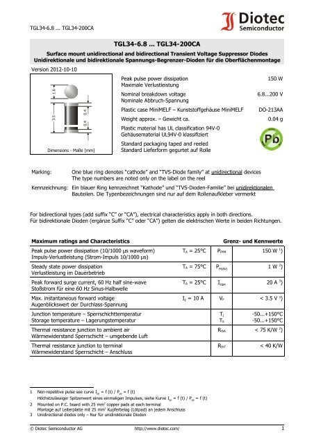
3.5<br />
1.6<br />
0.4 0.4<br />
Dimensions - Maße [mm]<br />
Peak pulse power dissipation<br />
Maximale Verlustleistung<br />
Nominal breakdown voltage<br />
Nominale Abbruch-Spannung<br />
Plastic case MiniMELF – Kunststoffgehäuse MiniMELF<br />
Weight approx. – Gewicht ca.<br />
Plastic material has UL classification 94V-0<br />
Gehäusematerial UL94V-0 klassifiziert<br />
Standard packaging taped and reeled<br />
Standard Lieferform gegurtet auf Rolle<br />
150 W<br />
<strong>6.8</strong>...200 V<br />
DO-213AA<br />
0.04 g<br />
Marking:<br />
One blue ring denotes “cathode” and “TVS-Diode family” at unidirectional devices<br />
The type numbers are noted only on the label on the reel<br />
Kennzeichnung: Ein blauer Ring kennzeichnet “Kathode” und “TVS-Dioden-Familie” bei unidirektionalen<br />
Bauteilen. Die Typenbezeichnungen sind nur auf dem Rollenaufkleber vermerkt<br />
For bidirectional types (add suffix “C” or “CA”), electrical characteristics apply in both directions.<br />
Für bidirektionale Dioden (ergänze Suffix “C” oder “CA”) gelten die elektrischen Werte in beiden Richtungen.<br />
Maximum ratings and Characteristics<br />
Peak pulse power dissipation (10/1000 µs waveform)<br />
Impuls-Verlustleistung (Strom-Impuls 10/1000 µs)<br />
Steady state power dissipation<br />
Verlustleistung im Dauerbetrieb<br />
Peak forward surge current, 60 Hz half sine-wave<br />
Stoßstrom für eine 60 Hz Sinus-Halbwelle<br />
Max. instantaneous forward voltage<br />
Augenblickswert der Durchlass-Spannung<br />
Grenz- und Kennwerte<br />
T A = 25°C P PPM 150 W 1 )<br />
T A = 75°C P M(AV)<br />
1 W 2 )<br />
T A = 25°C I FSM<br />
20 A 3 )<br />
I F<br />
= 10 A V F < 3.5 V 3 )<br />
Junction temperature – Sperrschichttemperatur<br />
Storage temperature – Lagerungstemperatur<br />
T j<br />
T S<br />
-50...+150°C<br />
-50...+150°C<br />
Thermal resistance junction to ambient air<br />
Wärmewiderstand Sperrschicht – umgebende Luft<br />
R thA < 75 K/W 2 )<br />
Thermal resistance junction to terminal<br />
Wärmewiderstand Sperrschicht – Anschluss<br />
R thT<br />
< 40 K/W<br />
1 Non-repetitive pulse see curve I PP<br />
= f (t) / P PP<br />
= f (t)<br />
Höchstzulässiger Spitzenwert eines einmaligen Impulses, siehe Kurve I PP<br />
= f (t) / P PP<br />
= f (t)<br />
2 Mounted on P.C. board with 25 mm 2 copper pads at each terminal<br />
Montage auf Leiterplatte mit 25 mm 2 Kupferbelag (Lötpad) an jedem Anschluss<br />
3 Unidirectional diodes only – Nur für unidirektionale Dioden<br />
© <strong>Diotec</strong> Semiconductor AG http://www.diotec.com/ 1
<strong>TGL34</strong>-<strong>6.8</strong> ... <strong>TGL34</strong>-<strong>200CA</strong><br />
Maximum ratings<br />
Type<br />
Typ<br />
Breakdown voltage at I T = 1 mA<br />
Abbruch-Spannung bei I T = 1 mA<br />
*) at / bei I T = 10 mA<br />
Stand-off voltage<br />
Sperrspannung<br />
Max. rev. current<br />
Max. Sperrstrom<br />
at / bei V WM<br />
Grenzwerte<br />
Max. clamping voltage<br />
Max. Begrenzer-Spannung<br />
at / bei I PPM (10/1000 µs)<br />
V BR [V] V WM [V] I D [µA] V C [V] I PPM [A]<br />
<strong>TGL34</strong>-<strong>6.8</strong> <strong>6.8</strong> ± 10% 6.12...7.48 *) 5.5 1000 10.8 13.9<br />
<strong>TGL34</strong>-<strong>6.8</strong>A <strong>6.8</strong> ± 5% 6.45...7.14 *) 5.8 1000 10.5 14.3<br />
<strong>TGL34</strong>-7.5 7.5 ± 10% 6.75...8.25 *) 6.0 500 11.7 12.8<br />
<strong>TGL34</strong>-7.5A 7.5 ± 5% 7.13...7.88 *) 6.4 500 11.3 13.3<br />
<strong>TGL34</strong>-8.2 8.2 ± 10% 7.38...9.02 *) 6.6 200 12.5 12.0<br />
<strong>TGL34</strong>-8.2A 8.2 ± 5% 7.79...8.61 *) 7.0 200 12.1 12.4<br />
<strong>TGL34</strong>-9.1 9.1 ± 10% 8.19...10.0 7.3 50 13.8 10.9<br />
<strong>TGL34</strong>-9.1A 9.1 ± 5% 8.65...9.55 7.7 50 13.4 11.2<br />
<strong>TGL34</strong>-10 10 ± 10% 9.0...11.0 8.1 10 15.0 10.0<br />
<strong>TGL34</strong>-10A 10 ± 5% 9.5...10.5 8.5 10 14.5 10.3<br />
<strong>TGL34</strong>-11 11 ± 10% 9.9...12.1 8.9 5 16.2 9.3<br />
<strong>TGL34</strong>-11A 11 ± 5% 10.5...11.6 9.4 5 15.6 9.6<br />
<strong>TGL34</strong>-12 12 ± 10% 10.8...13.2 9.7 5 17.3 8.7<br />
<strong>TGL34</strong>-12A 12 ± 5% 11.4...12.6 10.2 5 16.7 9.0<br />
<strong>TGL34</strong>-13 13 ± 10% 11.7...14.3 10.5 5 19.0 7.9<br />
<strong>TGL34</strong>-13A 13 ± 5% 12.4...13.7 11.1 5 18.2 8.2<br />
<strong>TGL34</strong>-15 15 ± 10% 13.5...16.5 12.1 5 22.0 <strong>6.8</strong><br />
<strong>TGL34</strong>-15A 15 ± 5% 14.3...15.8 12.8 5 21.2 7.1<br />
<strong>TGL34</strong>-16 16 ± 10% 14.4...17.6 12.9 5 23.5 6.4<br />
<strong>TGL34</strong>-16A 16 ± 5% 15.2...1<strong>6.8</strong> 13.6 5 22.5 6.7<br />
<strong>TGL34</strong>-18 18 ± 10% 16.2...19.8 14.5 5 26.5 5.7<br />
<strong>TGL34</strong>-18A 18 ± 5% 17.1...18.9 15.3 5 25.2 6.0<br />
<strong>TGL34</strong>-20 20 ± 10% 18.0...22.0 16.2 5 29.1 5.2<br />
<strong>TGL34</strong>-20A 20 ± 5% 19.0...21.0 17.1 5 27.7 5.4<br />
<strong>TGL34</strong>-22 22 ± 10% 19.8...24.2 17.8 5 31.9 4.7<br />
<strong>TGL34</strong>-22A 22 ± 5% 20.9...23.1 18.8 5 30.6 4.9<br />
<strong>TGL34</strong>-24 24 ± 10% 21.6...26.4 19.4 5 34.7 4.3<br />
<strong>TGL34</strong>-24A 24 ± 5% 22.8...25.2 20.5 5 33.2 4.5<br />
<strong>TGL34</strong>-27 27 ± 10% 24.3...29.7 21.8 5 39.1 3.8<br />
<strong>TGL34</strong>-27A 27 ± 5% 25.7...28.4 23.1 5 37.5 4.0<br />
<strong>TGL34</strong>-30 30 ± 10% 27.0...33.0 24.3 5 43.5 3.4<br />
<strong>TGL34</strong>-30A 30 ± 5% 28.5...31.5 25.6 5 41.4 3.6<br />
<strong>TGL34</strong>-33 33 ± 10% 29.7...36.3 2<strong>6.8</strong> 5 47.7 3.1<br />
<strong>TGL34</strong>-33A 33 ± 5% 31.4...34.7 28.2 5 45.7 3.3<br />
<strong>TGL34</strong>-36 36 ± 10% 32.4...39.6 29.1 5 52.0 2.9<br />
<strong>TGL34</strong>-36A 36 ± 5% 34.2...37.8 30.8 5 49.9 3.0<br />
<strong>TGL34</strong>-39 39 ± 10% 35.1...42.9 31.6 5 56.4 2.7<br />
<strong>TGL34</strong>-39A 39 ± 5% 37.1...41.0 33.3 5 53.9 2.8<br />
2 http://www.diotec.com/ © <strong>Diotec</strong> Semiconductor AG
<strong>TGL34</strong>-<strong>6.8</strong> ... <strong>TGL34</strong>-<strong>200CA</strong><br />
Maximum ratings<br />
Type<br />
Typ<br />
Breakdown voltage at I T = 1 mA<br />
Abbruch-Spannung bei I T = 1 mA<br />
*) at / bei I T = 10 mA<br />
Stand-off voltage<br />
Sperrspannung<br />
Max. rev. current<br />
Max. Sperrstrom<br />
at / bei V WM<br />
Grenzwerte<br />
Max. clamping voltage<br />
Max. Begrenzer-Spannung<br />
at / bei I PPM (10/1000 µs)<br />
V BR [V] V WM [V] I D [µA] V C [V] I PPM [A]<br />
<strong>TGL34</strong>-43 43 ± 10% 38.7...47.3 34.8 5 61.9 2.4<br />
<strong>TGL34</strong>-43A 43 ± 5% 40.9...45.2 3<strong>6.8</strong> 5 59.3 2.5<br />
<strong>TGL34</strong>-47 47 ± 10% 42.3...51.7 38.1 5 67.8 2.2<br />
<strong>TGL34</strong>-47A 47 ± 5% 44.7...49.4 40.2 5 64.8 2.3<br />
<strong>TGL34</strong>-51 51 ± 10% 45.9...56.1 41.3 5 73.5 2.0<br />
<strong>TGL34</strong>-51A 51 ± 5% 48.5...53.6 43.6 5 70.1 2.1<br />
<strong>TGL34</strong>-56 56 ± 10% 50.4...61.6 45.4 5 81 1.9<br />
<strong>TGL34</strong>-56A 56 ± 5% 53.2...58.8 47.8 5 77 1.9<br />
<strong>TGL34</strong>-62 62 ± 10% 55.8...68.8 50.2 5 89 1.7<br />
<strong>TGL34</strong>-62A 62 ± 5% 58.9...65.1 53.0 5 85 1.8<br />
<strong>TGL34</strong>-68 68 ± 10% 61.2...74.8 55.1 5 98 1.5<br />
<strong>TGL34</strong>-68A 68 ± 5% 64.6...71.4 58.1 5 92 1.6<br />
<strong>TGL34</strong>-75 75 ± 10% 67.5...82.5 60.7 5 108 1.4<br />
<strong>TGL34</strong>-75A 75 ± 5% 71.3...78.8 64.1 5 103 1.5<br />
<strong>TGL34</strong>-82 82 ± 10% 73.8...90.2 66.4 5 118 1.3<br />
<strong>TGL34</strong>-82A 82 ± 5% 77.9...86.1 70.1 5 113 1.3<br />
<strong>TGL34</strong>-91 91 ± 10% 81.9...100 73.7 5 131 1.1<br />
<strong>TGL34</strong>-91A 91 ± 5% 86.5...95.5 77.8 5 125 1.2<br />
<strong>TGL34</strong>-100 100 ± 10% 90.0...110 81.0 5 144 1.0<br />
<strong>TGL34</strong>-100A 100 ± 5% 95.0...105 85.5 5 137 1.1<br />
<strong>TGL34</strong>-110 110 ± 10% 99.0...121 89.2 5 158 0.9<br />
<strong>TGL34</strong>-110A 110 ± 5% 105...116 94.0 5 152 1.0<br />
<strong>TGL34</strong>-120 120 ± 10% 108...132 97.2 5 173 0.9<br />
<strong>TGL34</strong>-120A 120 ± 5% 114...126 102 5 165 0.9<br />
<strong>TGL34</strong>-130 130 ± 10% 117...143 105 5 187 0.8<br />
<strong>TGL34</strong>-130A 130 ± 5% 124...137 111 5 179 0.8<br />
<strong>TGL34</strong>-150 150 ± 10% 135...165 121 5 215 0.7<br />
<strong>TGL34</strong>-150A 150 ± 5% 143...158 128 5 207 0.7<br />
<strong>TGL34</strong>-160 160 ± 10% 144...176 130 5 230 0.7<br />
<strong>TGL34</strong>-160A 160 ± 5% 152...168 136 5 219 0.7<br />
<strong>TGL34</strong>-170 170 ± 10% 153...187 138 5 244 0.6<br />
<strong>TGL34</strong>-170A 170 ± 5% 162...179 145 5 234 0.6<br />
<strong>TGL34</strong>-180 180 ± 10% 162...198 146 5 258 0.6<br />
<strong>TGL34</strong>-180A 180 ± 5% 171...189 154 5 246 0.6<br />
<strong>TGL34</strong>-200 200 ± 10% 180...220 162 5 287 0.5<br />
<strong>TGL34</strong>-200A 200 ± 5% 190...210 171 5 274 0.5<br />
For bidirectional types (suffix “C” or “CA”), electrical characteristics apply in both directions.<br />
Für bidirektionale Dioden (Suffix “C” oder “CA”) gelten die elektrischen Werte in beiden Richtungen.<br />
© <strong>Diotec</strong> Semiconductor AG http://www.diotec.com/ 3
<strong>TGL34</strong>-<strong>6.8</strong> ... <strong>TGL34</strong>-<strong>200CA</strong><br />
120<br />
[%]<br />
100<br />
80<br />
100<br />
[%]<br />
80<br />
t = 10 µs<br />
r<br />
1<br />
60<br />
40<br />
I PP<br />
20<br />
P PP<br />
0<br />
0<br />
T A 50 100 150<br />
[°C]<br />
1<br />
Peak pulse power/current vs. ambient temperature )<br />
1<br />
Impuls-Spitzenleistung/Strom vs. Umgebungstemp. )<br />
60<br />
I PPM/2<br />
P<br />
PPM/2<br />
40<br />
I PP<br />
20<br />
P PP<br />
t P<br />
0<br />
0 t 1 2 3 [ms] 4<br />
10/1000µs - pulse waveform<br />
10/1000µs - Impulsform<br />
2<br />
10<br />
[kW]<br />
10<br />
1<br />
P PP<br />
0.1<br />
0.1µs t 1µs 10µs 100µs 1ms 10ms<br />
P<br />
Non repetitive peak pulse power versus pulse width (10/1000 wave form)<br />
Einzel-Impuls-Spitzenleistung in Abh. von der Pulsdauer (10/1000-Impuls)<br />
T j = 25°C<br />
V<br />
R<br />
= 1.0 V<br />
[pF]<br />
C j<br />
V R<br />
[V]<br />
Junction capacitance vs. reverse voltage (typical)<br />
Sperrschichtkapazität in Abh. v.d. Sperrspg. (typ.)<br />
The range of type numbers is graded to the international E 24 standard. The standard tolerance of the<br />
breakdown voltage for each type is ± 10%. Suffix “A” denotes a tolerance of ± 5% for the breakdown<br />
voltage.<br />
e.g.:<br />
<strong>TGL34</strong>-51C = bidirectional diode, V BR = 51 V (± 10%), V WM ≥ 41.3 V at I D = 5 μA<br />
<strong>TGL34</strong>-9.1A = unidirectional diode, V BR = 9.1 V (± 5%), V WM ≥ 7.7 V at I D = 50 μA<br />
Die Abstufung der Typen innerhalb der Reihe entspricht dem internationalen E 24-Standard. Die Toleranz der<br />
Abbruchspannung jedes einzelnen Typs beträgt in der Standardausführung ± 10%. Suffix “A” kennzeichnet<br />
eine Toleranz der Abbruchspannung von ± 5%.<br />
1 Mounted on P.C. board with 25 mm 2 copper pads at each terminal<br />
Montage auf Leiterplatte mit 25 mm 2 Kupferbelag (Lötpad) an jedem Anschluss<br />
4 http://www.diotec.com/ © <strong>Diotec</strong> Semiconductor AG