AN220 Watt-Hour Meter using PIC16C923 and CS5460 - 320Volt
AN220 Watt-Hour Meter using PIC16C923 and CS5460 - 320Volt
AN220 Watt-Hour Meter using PIC16C923 and CS5460 - 320Volt

Create successful ePaper yourself
Turn your PDF publications into a flip-book with our unique Google optimized e-Paper software.
<strong>AN220</strong><br />
<strong>Watt</strong>-<strong>Hour</strong> <strong>Meter</strong> <strong>using</strong> <strong>PIC16C923</strong> <strong>and</strong> <strong>CS5460</strong><br />
Authors:<br />
Brett Duane, Stephen Humberd<br />
Microchip Technology Inc.<br />
FIGURE 1:<br />
WATT-HOUR METER<br />
OVERVIEW<br />
This application note shows how to use a <strong>PIC16C923</strong><br />
microcontroller to control operation of the <strong>CS5460</strong><br />
power measurement integrated circuit from Cirrus<br />
Logic ® /Crystal Power Measurement, to drive a liquid<br />
crystal panel (“glass”), <strong>and</strong> to store <strong>and</strong> retrieve data<br />
<strong>using</strong> the 24C01 Serial EEPROM.<br />
Energy transferred between the line <strong>and</strong> load is measured<br />
by the <strong>CS5460</strong>. The <strong>PIC16C923</strong> initializes the<br />
<strong>CS5460</strong> with calibration data stored in the 24C01<br />
Serial EEPROM, records the total energy measured in<br />
the 24C01, <strong>and</strong> displays results on the LCD panel.<br />
INTRODUCTION<br />
Most forms of AC power measurement have already<br />
been patented by various companies, so measuring<br />
AC power in a product intended for sale often involves<br />
paying licensing fees to another company. The<br />
<strong>CS5460</strong> offers an integrated solution that provides a<br />
power <strong>and</strong> energy measurement sub-system, requiring<br />
only voltage <strong>and</strong> current sense inputs. In addition,<br />
calibration is accurate for any current waveform or<br />
power factor that may be encountered.<br />
By <strong>using</strong> the <strong>CS5460</strong>, a <strong>PIC16C923</strong> microcontroller, a<br />
24C01 Serial EEPROM, <strong>and</strong> an LCD panel, a simple<br />
<strong>and</strong> compact device is constructed that displays RMS<br />
voltage, RMS current, <strong>and</strong> the energy consumed by a<br />
load. These features are extended by including computation<br />
<strong>and</strong> display of apparent power, true power,<br />
<strong>and</strong> power factor.<br />
The <strong>PIC16C923</strong> LCD controller can drive an LCD panel<br />
with up to 4 common planes <strong>and</strong> up to 32 segments. 4K<br />
words of program memory, <strong>and</strong> 176 bytes of RAM are<br />
provided. A Synchronous Serial Peripheral (SSP) provides<br />
SPI TM communications with the <strong>CS5460</strong>.<br />
Inter-Integrated Circuit TM (I 2 C) communications with the<br />
24C01 Serial EEPROM are provided by firmware.<br />
The <strong>CS5460</strong> power/energy measurement IC measures<br />
instantaneous voltage <strong>and</strong> current four thous<strong>and</strong><br />
times a second <strong>and</strong> uses these measurements to<br />
compute VRMS, IRMS, instantaneous power, <strong>and</strong> accumulated<br />
energy results for read out. In addition, a<br />
pulse is generated whenever a user specified amount<br />
of energy transfers between the line <strong>and</strong> the load.<br />
HARDWARE<br />
On power-up, the <strong>PIC16C923</strong> microcontroller reads<br />
the calibration data, device serial number, <strong>and</strong> total<br />
energy from the 24C01, writes the calibration data to<br />
the <strong>CS5460</strong>, initializes the <strong>CS5460</strong>, <strong>and</strong> reads the<br />
state of the control buttons.<br />
If the control button state matches one of three patterns<br />
at RESET, a control mode is entered that allows<br />
setting the real time clock (RTC), clearing the total<br />
WHr <strong>and</strong> restoring default calibration values, or adjusting<br />
calibration constants.<br />
During normal operation, the <strong>PIC16C923</strong> counts<br />
pulses from the <strong>CS5460</strong>, reads <strong>CS5460</strong> data registers,<br />
drives the LCD panel to display the requested<br />
data, <strong>and</strong> monitors the control buttons. The pulses are<br />
used to update the total energy count <strong>and</strong> are periodically<br />
written to the 24C01.<br />
The <strong>CS5460</strong> measures line voltage <strong>and</strong> line current to<br />
compute power <strong>and</strong> energy transferred on the line.<br />
When a unit of energy has transferred between the<br />
line <strong>and</strong> the load, a pulse with direction indication is<br />
generated.<br />
© 2000 Microchip Technology Inc. DS00220A-page 1
<strong>AN220</strong><br />
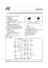
FIGURE 2:<br />
L<br />
N<br />
G<br />
VOLTAGE<br />
SENSE<br />
24C01<br />
SYSTEM BLOCK DIAGRAM<br />
CURRENT SENSE<br />
BUTTONS<br />
<strong>CS5460</strong><br />
<strong>PIC16C923</strong><br />
LCD<br />
L<br />
N<br />
G<br />
<strong>CS5460</strong> Power/Energy Measurement Circuit<br />
The <strong>CS5460</strong> measures the instantaneous line voltage<br />
<strong>and</strong> line current, four thous<strong>and</strong> times a second. These<br />
measurements are used to compute instantaneous<br />
power, energy transferred since the last measurement,<br />
RMS voltage, RMS current, <strong>and</strong> accumulated energy<br />
transferred. All measurements <strong>and</strong> results can be read<br />
by an external controller, via the SPI interface. A transfer<br />
of energy is also indicated by a pulse output at the<br />
EOUT pin. The direction of transfer is indicated by the<br />
EDIR pin.<br />
There is no switching provided, or required for operation<br />
from either 120V or 220V, 50Hz or 60Hz. However,<br />
accuracy will decrease when operating from a<br />
line voltage different than the calibration conditions.<br />
By <strong>using</strong> the instantaneous voltage <strong>and</strong> current, the<br />
<strong>CS5460</strong> computes the RMS voltage, RMS current,<br />
<strong>and</strong> instantaneous power. The instantaneous power is<br />
integrated at the sampling rate (4000Hz) to compute<br />
the energy transferred. A new RMS value is available<br />
every 4000 samples. Samples are taken 4000 times<br />
per second, or about 67 times per 60Hz cycle.<br />
When the integrated energy exceeds 10 WSec, a fixed<br />
width pulse is generated at the EOUT pin <strong>and</strong> the integrated<br />
energy is reduced by 10 WSec. These pulses<br />
are counted to record energy consumption. The EDIR<br />
pin indicates the direction that the energy flows (reactive<br />
loads can return energy to the line). Depending on<br />
the state of the EDIR pin, the pulse at the EOUT pin<br />
causes the <strong>PIC16C923</strong> to either increment, or decrement<br />
the total energy count.<br />
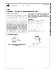
FIGURE 3:<br />
CIRCUITS THAT MONITOR<br />
LINE CURRENT (A) AND LINE<br />
VOLTAGE (B)<br />
GROUND<br />
NEUTRAL<br />
LINE<br />
Communication with the <strong>CS5460</strong> takes place over a<br />
4-wire SPI link with the <strong>PIC16C923</strong>. The <strong>CS5460</strong> is<br />
configured <strong>and</strong> controlled over this link. Calculation<br />
results are also read by the controller over this link.<br />
The line voltage may be sampled <strong>using</strong> a transformer<br />
or resistor divider. The differential input is limited to<br />
150mVRMS. In this application, line voltage is detected<br />
from the secondary winding of the power supply transformer,<br />
T2 (see Figure 3B <strong>and</strong> Figure 5). When operating<br />
from 120V, there is about an 8V peak at VIN+ or<br />
VIN-. When operating from 220V, there is about a<br />
14.7V peak. This voltage is further reduced by a resistor<br />
network before being applied to the <strong>CS5460</strong> (see<br />
Figure 4A).<br />
The line current may be sampled <strong>using</strong> a current<br />
transformer or shunt resistor. Depending on the gain of<br />
the input channel, the differential input is limited to<br />
either 30 mVRMS (gain = 50), or 150 mVRMS<br />
(gain = 10). In this application, the current channel<br />
gain is 10, for a maximum input voltage of 150 mVRMS.<br />
This voltage is provided by the current sense transformer<br />
T1 <strong>and</strong> resistor R21, <strong>and</strong> is reduced by a resistor<br />
network similar to the line voltage channel (see<br />
Figure 3A <strong>and</strong> Figure 4B).<br />
SOURCE<br />
LINE<br />
R21<br />
56Ω, ½W<br />
3A<br />
T2<br />
T1<br />
IIN+<br />
LOAD<br />
VIN+<br />
D1<br />
NEUTRAL<br />
3B<br />
D2<br />
VIN-<br />
DS00220A-page 2<br />
© 2000 Microchip Technology Inc.
<strong>AN220</strong><br />
FIGURE 4:<br />
R10<br />
VIN+<br />
100k<br />
R12<br />
VIN-<br />
100k<br />
R20<br />
IIN+<br />
180k<br />
10k<br />
<strong>CS5460</strong> INPUT ATTENUATION<br />
CIRCUITS<br />
R11<br />
1k<br />
R9<br />
C25<br />
0.01µF<br />
R25<br />
301<br />
R23<br />
301<br />
R22<br />
301<br />
4A<br />
C24<br />
0.01µF<br />
9 VIN+<br />
C15 <strong>CS5460</strong><br />
4700pF<br />
10 VIN-<br />
16<br />
IIN+<br />
<strong>CS5460</strong><br />
<strong>PIC16C923</strong> Microcontroller<br />
The <strong>PIC16C923</strong> microcontroller provides a Liquid<br />
Crystal Display (LCD) driver module that drives the<br />
LCD panel directly. It also communicates with the<br />
<strong>CS5460</strong> <strong>using</strong> the 4-wire SPI link (SDI, SDO, SCL,<br />
<strong>and</strong> CS) to issue comm<strong>and</strong>s, write calibration data,<br />
<strong>and</strong> read measurement <strong>and</strong> calculation results. The<br />
microcontroller also controls the <strong>CS5460</strong> RESET line<br />
(see Figure 6).<br />
The controller system oscillator is driven by the<br />
CPUCLK output of the <strong>CS5460</strong> <strong>and</strong> operates at<br />
4.096MHz. The system oscillator is configured for XT<br />
mode, but any crystal mode will work. A 32.768kHz<br />
crystal has been provided for use with the Timer1<br />
oscillator. Since the <strong>CS5460</strong> provides a 4.096MHz<br />
clock source to the <strong>PIC16C923</strong>, either source can be<br />
used for the real time clock source. The demonstration<br />
units have been configured to use the <strong>CS5460</strong> clock<br />
source for the real time clock.<br />
Power Supply<br />
A transformer isolated power supply provides power<br />
for the <strong>Watt</strong>-<strong>Hour</strong> <strong>Meter</strong>. The transformer primary is<br />
connected to the line between the power source <strong>and</strong><br />
the current sense transformer. The AC voltage from<br />
the transformer secondary is used to detect the line<br />
voltage <strong>and</strong> is coupled to the <strong>CS5460</strong> through a resistor<br />
network (see Figure 4A).<br />
The AC from the center tapped secondary is full wave<br />
rectified, filtered, <strong>and</strong> provided to the 5V regulator. The<br />
5V loads are the “power-on” LED, the <strong>CS5460</strong>, <strong>and</strong><br />
the <strong>PIC16C923</strong>. The majority of the current is drawn<br />
by the LED, about 7.5mA. The rest of the circuit draws<br />
less than 5mA.<br />
FIGURE 5:<br />
4B<br />
POWER SUPPLY CIRCUIT<br />
FIGURE 6:<br />
4.096MHZ<br />
C21<br />
0.1µF<br />
CONNECTIONS BETWEEN<br />
THE <strong>CS5460</strong> AND THE<br />
<strong>PIC16C923</strong><br />
CS<br />
9 8 7<br />
1<br />
24<br />
XOUT XIN<br />
2<br />
10<br />
RESET<br />
CPUCLK CPUCLK<br />
RA4<br />
SDI<br />
23<br />
SDO<br />
12<br />
EDIR RB1<br />
5<br />
SCLK SCLK 22<br />
EDIR EDIR<br />
13<br />
EOUT RB0<br />
6<br />
SDI SDO 21<br />
14<br />
EOUT EOUT SCLK RC3<br />
7<br />
CS CS<br />
15<br />
RESET<br />
19<br />
RESET SDI RC4<br />
U2<br />
<strong>CS5460</strong><br />
SDO<br />
CPUCLK<br />
16<br />
RC5<br />
24 OSC1<br />
NC<br />
25<br />
OSC2 U1<br />
+5V<br />
<strong>PIC16C923</strong><br />
R19 10k<br />
RA2<br />
C14<br />
0.015µF<br />
15 IIN-<br />
VIN+<br />
T2<br />
LINE<br />
D1<br />
U4<br />
78L05<br />
I O +5V<br />
G<br />
D2<br />
NEUTRAL C13 C12<br />
1000µF 0.1µF<br />
VIN-<br />
© 2000 Microchip Technology Inc. DS00220A-page 3
<strong>AN220</strong><br />
Interface to 24C01 Serial EEPROM<br />
The Serial EEPROM stores the calibration constants<br />
required by the <strong>CS5460</strong> for accurate measurements,<br />
<strong>and</strong> the total accumulated energy transferred. The<br />
controller communicates with the 24C01 via an I 2 C<br />
interface. Since the SSP module is already in use supporting<br />
SPI communications with the <strong>CS5460</strong>, the<br />
<strong>PIC16C923</strong> must perform I 2 C communications in firmware,<br />
<strong>using</strong> RA0 (SCL) <strong>and</strong> RA1 (SDA) (see Figure 7).<br />
Either the 24C01, or the <strong>PIC16C923</strong>, may pull the<br />
SDA line low, depending on the direction of the data<br />
flow. Since the <strong>PIC16C923</strong> always drives the SCL line,<br />
no pull-up resistor was included. A memory map of the<br />
Serial EEPROM is included in Appendix A.<br />
FIGURE 7:<br />
CONNECTION BETWEEN THE<br />
24C01 AND THE <strong>PIC16C923</strong><br />
User Interface<br />
The user interface consists of the LCD display, four<br />
control push buttons, one reset push button, <strong>and</strong> the<br />
“power-on” LED.<br />
The <strong>PIC16C923</strong> LCD module directly drives the LCD<br />
panel. The panel can display eight, 7-segment digits<br />
(numbers only), seven decimal points <strong>and</strong> three colons.<br />
When pushed, each of the four push buttons pull the<br />
respective port pin low. The buttons are connected to<br />
PORTB <strong>and</strong> are numbered from 1 to 4, left to right.<br />
FIRMWARE<br />
+5V<br />
4.7k<br />
1<br />
8<br />
+5V VCC SDA SDA<br />
2<br />
7<br />
SCL SCL A0<br />
6<br />
3 A1<br />
WP<br />
4<br />
5<br />
GND A2<br />
C21<br />
U3<br />
24C01<br />
0.1µF<br />
SCL<br />
SDA<br />
9 6 5<br />
RA1<br />
RA0<br />
U1<br />
<strong>PIC16C923</strong><br />
The <strong>CS5460</strong> transfers data in 4 byte groups (32-bits).<br />
The first byte contains the register address <strong>and</strong> a bit<br />
specifying a read or write operation. The remaining 3<br />
bytes are transferred to or from one of the internal registers.<br />
The <strong>CS5460</strong> also accepts single byte comm<strong>and</strong>s.<br />
Such comm<strong>and</strong>s are followed by 3 SYNC<br />
bytes that are treated as NOP bytes.<br />
A write comm<strong>and</strong> is followed by 3 bytes of data to the<br />
<strong>CS5460</strong>, to be written to the selected register. A read<br />
comm<strong>and</strong> causes the 3 bytes of the selected register<br />
to be output by the <strong>CS5460</strong>.<br />
If the comm<strong>and</strong> byte specifies an operation to be performed,<br />
or a read operation, the remaining 3 bytes<br />
transmitted by the <strong>PIC16C923</strong> should be SYNC0<br />
bytes (0xFE).<br />
R3<br />
Power-up <strong>and</strong> RESET<br />
A Power-on Reset initializes the <strong>CS5460</strong> <strong>and</strong> clears<br />
the real time clock.<br />
Initialize On-Chip Peripherals<br />
Timer1, Timer2, the SSP, <strong>and</strong> Ports A, B, <strong>and</strong> C are<br />
configured for operation. Interrupts are also enabled.<br />
The LCD module is then configured.<br />
Clear the LCD Display<br />
All segment data registers are cleared to blank the display.<br />
This routine is called frequently during normal<br />
operation.<br />
Initialize Variables<br />
If this was a cold start (power has just been applied),<br />
the memory contents are cleared <strong>and</strong> the calibration<br />
constants are copied from the 24C01 to the <strong>CS5460</strong>.<br />
The device serial number <strong>and</strong> the current total WHr<br />
are retrieved from the 24C01. If a warm start has<br />
occurred, only the serial number is retrieved.<br />
Initialize the <strong>CS5460</strong><br />
The <strong>CS5460</strong> is configured to generate a pulse at the<br />
EOUT pin for each 10 WSec measured (360 pulses<br />
per WHr). For 100W loads, this causes 10 pulses per<br />
second to be generated.<br />
Check Button Status<br />
The status of the four push buttons is checked. If all<br />
four buttons are pressed, the total WHr value in the<br />
24C01 is cleared <strong>and</strong> calibration values are copied<br />
from the EEPROM to the <strong>CS5460</strong>. If the center two<br />
buttons are pressed, the real time clock is set. If the<br />
outer two buttons are pressed, the <strong>Watt</strong>-<strong>Hour</strong> meter<br />
enters Calibration mode (see Table 1). If no buttons<br />
are pressed, the <strong>CS5460</strong> begins continuous measurements.<br />
Execution proceeds to the scrolling start-up<br />
message.<br />
TABLE 1:<br />
Buttons<br />
1 2 3 4<br />
BUTTON STATES CHECKED<br />
DURING RESET<br />
Control Mode<br />
X X X X Clear WHr, restore<br />
calibration values<br />
X X Set Clock<br />
X X Calibration<br />
Display the Start-up Message<br />
A start-up message is displayed on the LCD. This<br />
message scrolls across the display until any of the four<br />
buttons is pressed. This message displays the device<br />
name <strong>and</strong> serial number.<br />
DS00220A-page 4<br />
© 2000 Microchip Technology Inc.
<strong>AN220</strong><br />
Normal Operation<br />
Results of the various calculations are displayed on<br />
the LCD. Each result is displayed for two seconds with<br />
an update after one second. If no buttons are pressed,<br />
the next mode is displayed. Holding any button keeps<br />
the display in the present mode, for as long as the button<br />
is held. New results will be displayed each second<br />
(see Table 2).<br />
TABLE 2:<br />
Display<br />
HH:MM:SS<br />
E<br />
C<br />
AP<br />
TP<br />
PF<br />
Hr<br />
DISPLAY MODES<br />
Time<br />
Value Displayed<br />
RMS Voltage<br />
RMS Current<br />
Apparent Power<br />
True Power<br />
Power Factor<br />
Total WHr<br />
Time<br />
The first result displayed is the time of day in the form<br />
HH:MM:SS. If the time of day was not set at RESET,<br />
this indicates the time since power-up (days are not<br />
recorded).<br />
RMS Voltage<br />
The RMS voltage is computed by reading the RMS<br />
voltage value from the <strong>CS5460</strong>. This is a 24-bit value<br />
with a range of 0.000 to 1.000, representing a fraction<br />
of the full scale voltage. The 16 most significant bits<br />
are multiplied by the full scale voltage (as 16-bits) to<br />
produce the actual RMS voltage on the line, as a<br />
16-bit binary number. This is converted to a 5 digit<br />
packed BCD number. The LCD display is blanked <strong>and</strong><br />
“E” <strong>and</strong> the appropriate decimal point are displayed.<br />
The packed BCD number is then displayed, after<br />
determining which digits (leading zeros) should remain<br />
blank.<br />
After one second, the value is updated <strong>and</strong> displayed<br />
again. After another second, execution proceeds to<br />
the next mode if no buttons were pressed. If a button<br />
was pressed, the two-second counter that controls<br />
when the next subroutine should be executed is<br />
cleared, extending the time that the value is displayed.<br />
This code is repeated in all display subroutines.<br />
RMS Current<br />
The RMS current is computed <strong>and</strong> displayed similar to<br />
the RMS voltage. The only differences are the full<br />
scale current is used, a “C” is displayed <strong>and</strong> a different<br />
decimal point is turned on. The button state is again<br />
checked to see if execution should remain in this subroutine.<br />
Apparent Power<br />
The apparent power is computed in a subroutine<br />
(CalcAP), called by both the apparent power loop<br />
(APLoop) <strong>and</strong> the power factor loop (PFLoop). The<br />
apparent power is computed by reading the RMS voltage<br />
<strong>and</strong> RMS current from the <strong>CS5460</strong>, as before.<br />
The 16 most significant bits of each are multiplied<br />
together, giving a 32-bit result. The 16 most significant<br />
bits of the result are multiplied with the full scale<br />
apparent power (16-bits) to get the actual apparent<br />
power in volt • amps in binary. The 16 most significant<br />
bits are returned for use by the calling subroutines.<br />
APLoop then converts the apparent power in binary<br />
(16-bits) to a 5-digit packed BCD number for display.<br />
The LCD display is blanked, “AP” is displayed <strong>and</strong><br />
after determining which digits should remain blanked<br />
(leading zeros), the apparent power is displayed. The<br />
buttons are again checked, as before, to determine if<br />
execution should remain in this subroutine.<br />
True Power<br />
The <strong>CS5460</strong> was programmed to generate a pulse<br />
whenever 10 WSec of energy has been transferred.<br />
For a 250W load, 25 pulses each second will be generated.<br />
These pulses have been processed in an Interrupt<br />
Service Routine. When 360 pulses have been<br />
accumulated, 3600 WSec or 1 WHr has been transferred.<br />
The total WHr is then incremented. The pulse<br />
count is also recorded for each second.<br />
The apparent power is computed in a subroutine<br />
(CalcTP), called by both the true power loop<br />
(TPLoop) <strong>and</strong> the power factor loop (PFLoop). CalcTP<br />
multiplies the number of pulses received during<br />
the last second by 10 to compute the true power consumed<br />
by the load. The result is returned as the true<br />
power in watts as a 16-bit binary number.<br />
TPLoop converts <strong>and</strong> displays the true power in the<br />
same way as APLoop displays apparent power. The<br />
only difference is that “TP” is displayed instead of<br />
“AP”. The buttons are again checked as before to<br />
determine if execution should remain in this subroutine.<br />
Power Factor (PF)<br />
The power factor is computed by calling the CalcAP<br />
subroutine to get apparent power in volt • amps <strong>and</strong><br />
the CalcTP subroutine to get true power in watts. The<br />
true power is divided by the apparent power to get the<br />
power factor as a binary result, in the range of 0.000 to<br />
1.000. The binary power factor is multiplied by 1000<br />
<strong>and</strong> converted to a BCD number for display. The<br />
appropriate decimal point is turned on.<br />
The buttons are checked as before to determine if<br />
execution should remain in the power factor<br />
subroutine.<br />
© 2000 Microchip Technology Inc. DS00220A-page 5
<strong>AN220</strong><br />
If apparent power is equal to 0, there is no load<br />
(IRMS = 0). This can result in a division by zero condition.<br />
If a division by zero is detected, a PF of 1.000 is<br />
reported.<br />
The calculated power factor can also greatly exceed<br />
1.0. When this occurs, the power factor is reported as<br />
being 1.000. This occurs when the load characteristics<br />
are rapidly changing (as when a motor is starting). All<br />
the measurements are not taken at exactly the same<br />
time <strong>and</strong> the RMS values are calculated over a one<br />
second period. When the load reaches a steady state<br />
condition, the power factor will again be correct.<br />
Energy (<strong>Watt</strong>-<strong>Hour</strong>s)<br />
The WHLoop simply displays the WHr counter value.<br />
The binary count is converted to BCD. The BCD number<br />
is then displayed with leading zeros blanked, <strong>using</strong><br />
the same subroutine used by the apparent power <strong>and</strong><br />
true power displays. The WHr counter is 16-bits long,<br />
allowing a maximum of 65,535 WHr to be displayed.<br />
When this count is exceeded, the count rolls over to 0.<br />
Control Modes<br />
If any of the three control modes was selected during<br />
RESET, execution branches to one of these modules<br />
to control how the <strong>Watt</strong>-<strong>Hour</strong> meter functions.<br />
When the control mode is terminated, a warm start<br />
RESET is executed.<br />
Calibrating the <strong>Watt</strong>-<strong>Hour</strong> <strong>Meter</strong><br />
The user is given the opportunity to adjust the calibration<br />
constants. These constants will not be stored to the<br />
24C01. When reset, <strong>using</strong> the reset button, the calibration<br />
values entered in the Calibrate mode will be used<br />
for making measurements <strong>and</strong> operation will resume as<br />
normal, except that the new calibration values are used.<br />
If reset by removing power, or reset while pressing all<br />
four buttons (clear total WHr), the constants stored in<br />
the 24C01 will be used for operation.<br />
Enter Calibration mode by holding the two outer buttons<br />
while pressing the reset button. The first three<br />
digits display “CAL”, <strong>and</strong> the remaining digits indicate<br />
which constant is being adjusted. “CAL EOFF” will be<br />
displayed first. This indicates that the value displayed<br />
the next time button 2 is pressed, will be the calibration<br />
constant for the voltage offset. Pressing button 2 again<br />
displays the constant’s value.<br />
The decimal point is next to the digit to be modified.<br />
Pressing button 3 will move the decimal point to the<br />
next digit to the right. Pressing button 4 will increment<br />
that digit. Each digit will cycle from 0 to F, then back to<br />
0. Only that digit will be affected. Pressing button 1 at<br />
any time will cause the value for that constant to be<br />
sent to the <strong>CS5460</strong> <strong>and</strong> display the next constant<br />
name. See Table 3 for button functions.<br />
TABLE 3:<br />
Button<br />
1 2 3 4<br />
X<br />
X<br />
X<br />
CALIBRATION MODE<br />
BUTTON FUNCTIONS<br />
X<br />
Function<br />
Writes constant to<br />
<strong>CS5460</strong> <strong>and</strong> displays next<br />
constant name<br />
Displays each constant<br />
name <strong>and</strong> its value in turn<br />
Selects next digit <strong>and</strong><br />
moves decimal point<br />
Increments selected digit<br />
Table 4 shows the constant names <strong>and</strong> typical values.<br />
It is essential that the offsets be minimized before setting<br />
the gains.<br />
To set the offsets, remove AC power from the<br />
<strong>Watt</strong>-<strong>Hour</strong> meter <strong>and</strong> apply DC power of 8 to 12 VDC<br />
to C13. Adjust the offset constants for minimum RMS<br />
results (there is a null in both the current <strong>and</strong> voltage<br />
channels). Record the offsets.<br />
Apply AC power to the <strong>Watt</strong>-<strong>Hour</strong> meter <strong>and</strong> remove<br />
the DC power from C13. Applying power in this order<br />
prevents a loss of power to the <strong>CS5460</strong>. If power is<br />
lost, reenter the offset values before adjusting the gain<br />
values. Apply a known resistive load to the <strong>Watt</strong>-<strong>Hour</strong><br />
meter output. Adjust the voltage <strong>and</strong> current gain constants<br />
so the indicated RMS voltage <strong>and</strong> current<br />
match the actual load voltage <strong>and</strong> current. Adjust the<br />
pulse rate gain so the indicated true power matches<br />
the actual load power. Record the gain constants.<br />
Resetting the device now uses the constants just<br />
found. If the total <strong>Watt</strong>-<strong>Hour</strong>s is cleared, the original<br />
constants will be restored.<br />
The software was designed for demonstration purposes;<br />
therefore, the calibration constants cannot be<br />
written to the serial EEPROM. If desired, the user can<br />
modify the code to write the new calibration constants<br />
to the EEPROM.<br />
DS00220A-page 6<br />
© 2000 Microchip Technology Inc.
<strong>AN220</strong><br />
TABLE 4:<br />
Indication<br />
CALIBRATION MODE INDICATIONS, CONSTANT AND TYPICAL VALUES<br />
Constant<br />
Calibration Value<br />
(120V, 10A)<br />
<strong>CS5460</strong> Default<br />
EOFF Voltage Offset 0x00CCBB = +0.00624 0x000000 = 0.00000<br />
COFF Current Offset 0xFEB320 = -0.01015 0x000000 = 0.00000<br />
E GA Voltage Gain 0x2C2F62 = 0.69039 0x400000 = 1.00000<br />
C GA Current Gain 0x298610 = 0.64917 0x400000 = 1.00000<br />
P GA Pulse Rate Gain 0x01FEF2 = 510.95 0x0FA000 = 4000.000<br />
Clear Total <strong>Watt</strong>-<strong>Hour</strong>s<br />
This option causes the total WHr to be cleared from<br />
the 24C01 <strong>and</strong> RAM, <strong>and</strong> copies calibration data<br />
stored in the 24C01 back to the <strong>CS5460</strong>. The word<br />
“CLEAR” is displayed until the buttons are released.<br />
Setting the Real Time Clock<br />
“CL” is displayed in the two digits at the left edge of the<br />
display. The current time is displayed in the remaining<br />
six digits.<br />
If buttons 2 <strong>and</strong> 4 are pressed together, the hours are<br />
incremented. If buttons 3 <strong>and</strong> 4 are pressed, the minutes<br />
are incremented. If the minutes roll over from 59<br />
to 0, the hours will not be affected. If button 1 is<br />
pressed, “CL” is cleared from the display <strong>and</strong> execution<br />
proceeds to the main loop. Pressing Button 2, 3,<br />
or 4 alone has no effect (see Table 5).<br />
TABLE 5:<br />
Button<br />
1 2 3 4<br />
X<br />
CLOCK SET MODE BUTTON<br />
FUNCTIONS<br />
Function<br />
Done setting clock<br />
X X Increment hours<br />
X X Increment minutes<br />
POSSIBLE ENHANCEMENTS<br />
An idea to simplify the calibration process is presented,<br />
along with ideas for adding a battery backup<br />
<strong>and</strong> event logging.<br />
Power Factor<br />
As reactive loads draw current out of phase with the<br />
line voltage, there is an associated phase angle. The<br />
cosine of this angle provides the power factor.<br />
The power factor will never exceed 1.000. Resistive<br />
loads will show a very high power factor, while reactive<br />
loads, such as motors, will show lower power factors.<br />
Loads with great harmonic content (such as most<br />
power supplies) will also indicate a low power factor.<br />
Power Factor Correcting (PFC) loads will indicate very<br />
high power factors.<br />
Calibration<br />
The calibration process assumes the user has the time<br />
<strong>and</strong> underst<strong>and</strong>ing to determine the calibration constants.<br />
This process can be greatly simplified. The<br />
<strong>CS5460</strong> has the capability of determining offsets <strong>and</strong><br />
gains. By comm<strong>and</strong>ing the <strong>CS5460</strong> to perform an offset<br />
calibration, the offset constants can be found very<br />
quickly. The calibration program would indicate the<br />
measured value being calibrated <strong>and</strong> allow the user to<br />
adjust the constant, without actually having to know<br />
what the constant was. When a satisfactory measurement<br />
is achieved, the constant would then be written<br />
to the 24C01.<br />
The code presented in this application note almost<br />
completely fills the first code page of the <strong>PIC16C923</strong>.<br />
The second code page could be dedicated to a calibration<br />
program.<br />
Battery Backup<br />
Some users may wish to have the real time clock continue<br />
to run, even during a loss of power. This<br />
becomes possible by adding a backup battery to<br />
power the <strong>PIC16C923</strong> <strong>and</strong> allow the Timer1 oscillator<br />
to operate. This would be the time base for the real<br />
time clock. The code to use Timer1 <strong>and</strong> its oscillator<br />
has been included. To extend the life of the battery, it<br />
would power only the <strong>PIC16C923</strong>.<br />
Event Logging<br />
The 24C01 provides 128 bytes of non-volatile<br />
EEPROM memory. Currently, only 17 bytes are used<br />
for storing calibration data, total energy, <strong>and</strong> a device<br />
serial number. The remaining memory could be used<br />
to record power line events, such as black-outs,<br />
brown-outs, surges <strong>and</strong> load peaks. With a real time<br />
clock, the times of these events could also be<br />
recorded. Recording black-outs <strong>and</strong> brown-outs would<br />
require that the backup battery also power the 24C01.<br />
© 2000 Microchip Technology Inc. DS00220A-page 7
<strong>AN220</strong><br />
APPENDIX A: EEPROM DATA MAP APPENDIX B: SOURCES<br />
Address<br />
0x00<br />
0x01<br />
0x02<br />
0x03<br />
0x04<br />
0x05<br />
0x06<br />
0x07<br />
0x08<br />
0x09<br />
0x0A<br />
0x0B<br />
0x0C<br />
0x0D<br />
0x0E<br />
0x0F<br />
0x10<br />
0x11<br />
Description<br />
Device Serial Number<br />
Voltage Offset MSB<br />
Voltage Offset<br />
Voltage Offset LSB<br />
Current Offset MSB<br />
Current Offset<br />
Current Offset LSB<br />
Voltage Gain MSB<br />
Voltage Gain<br />
Voltage Gain LSB<br />
Current Gain MSB<br />
Current Gain<br />
Current Gain LSB<br />
<strong>Watt</strong>-<strong>Hour</strong> MSB<br />
<strong>Watt</strong>-<strong>Hour</strong> LSB<br />
Pulse Rate Gain MSB<br />
Pulse Rate Gain<br />
Pulse Rate Gain LSB<br />
The LCD routines came from PICDEM-3 TM . Adjustments<br />
may have been made to the segment <strong>and</strong> common<br />
definitions to account for the use of a different<br />
LCD panel than was used in PICDEM-3.<br />
The BIN2BCD routine is loosely based on the<br />
B2_BCD_Looped routine in BCD.ASM of application<br />
note AN544. This function was originally written for the<br />
PIC17CXXX family, but it has been modified for the<br />
PIC16CXXX family.<br />
The multiply <strong>and</strong> divide math routines were copied<br />
from application note AN617.<br />
The data sheet for the <strong>PIC16C923</strong> can be found at<br />
http://www.microchip.com. Search for “DS30444E” or<br />
“<strong>PIC16C923</strong>”.<br />
The data sheet for the 24C01 can be found at<br />
http://www.microchip.com. Search for “DS20071J” or<br />
“24C01”.<br />
The data sheet for the <strong>CS5460</strong> can be found at<br />
http://www.crystal.com. Search for “DS279PP3” or<br />
“<strong>CS5460</strong>”.<br />
DS00220A-page 8<br />
© 2000 Microchip Technology Inc.
<strong>AN220</strong><br />
APPENDIX C:<br />
SCHEMATICS<br />
FIGURE C-1:<br />
<strong>PIC16C923</strong> CONNECTIONS<br />
RESET<br />
S1<br />
1<br />
2<br />
TO<br />
<strong>CS5460</strong><br />
+5V<br />
4<br />
3<br />
C5<br />
C6<br />
C7<br />
C8<br />
R2<br />
10k<br />
TO <strong>CS5460</strong><br />
C4<br />
.1µF<br />
RESET<br />
EDIR<br />
EOUT<br />
SCLK<br />
SDI<br />
SDO<br />
.47µF<br />
.47µF<br />
.47µF<br />
.1µF<br />
+5V<br />
CPUCLK<br />
TO 24C01<br />
NC<br />
10 RA4<br />
RD5 60<br />
11 RA5 RG6 59<br />
26 RC0 RF0 44<br />
12 RB1<br />
RG5 58<br />
13 RB0<br />
RG4 57<br />
14 U1<br />
RC3<br />
RG3 56<br />
15 16C923PLCC<br />
RC4<br />
RG2 55<br />
16 RC5<br />
RG1 54<br />
17 C1<br />
RG0 53<br />
18 C2<br />
RG7 52<br />
19 VLCD2<br />
RF7 51<br />
20 VLCD3<br />
RF6 50<br />
21 AVDD<br />
RF5 49<br />
22 VDD<br />
RF4 48<br />
23 VSS<br />
RF3 47<br />
24 OSC1<br />
RF2 46<br />
25 OSC2<br />
RF1 45<br />
Y1<br />
SCL<br />
SDA<br />
CS<br />
FROM BUTTONS<br />
RB6<br />
RB7<br />
RB5<br />
RB4<br />
C10<br />
.1µF<br />
+5V<br />
9<br />
8<br />
7<br />
6<br />
5<br />
4<br />
3<br />
2<br />
1<br />
68<br />
67<br />
66<br />
65<br />
64<br />
63<br />
62<br />
61<br />
RA3<br />
RA2<br />
VSS<br />
RA1<br />
RA0<br />
RB2<br />
RB3<br />
MCLR<br />
NC<br />
RB4<br />
RB5<br />
RB7<br />
RB6<br />
VDD<br />
COM0<br />
RD7<br />
RD6<br />
27 RC1<br />
28 RC2<br />
29 VLCD1<br />
30 VLCDADJ<br />
31 RD0<br />
32 RD1<br />
33 RD2<br />
34 RD3<br />
35 RD4<br />
36 RE7<br />
37 RE0<br />
38 RE1<br />
39 RE2<br />
40 RE3<br />
41 RE4<br />
42 RE5<br />
43 RE6<br />
COM1<br />
COM2<br />
COM3<br />
SEG26<br />
SEG25<br />
SEG24<br />
SEG23<br />
SEG22<br />
SEG21<br />
SEG20<br />
SEG19<br />
SEG18<br />
SEG17<br />
SEG16<br />
SEG15<br />
SEG14<br />
SEG13<br />
SEG12<br />
32.768kHZ<br />
C1 C2<br />
33pF 33pF<br />
C3<br />
.47µF<br />
SEG00<br />
SEG01<br />
SEG02<br />
SEG03<br />
SEG04<br />
R1<br />
124k<br />
SEG05<br />
SEG06<br />
SEG07<br />
SEG08<br />
SEG09<br />
SEG10<br />
SEG11<br />
© 2000 Microchip Technology Inc. DS00220A-page 9
<strong>AN220</strong><br />
FIGURE C-2:<br />
LCD, 24C01, PUSH BUTTONS<br />
LCD DISPLAY<br />
SEG19<br />
SEG21<br />
SEG15<br />
SEG13<br />
SEG10<br />
SEG07<br />
SEG04<br />
SEG01<br />
LCD1<br />
COM3<br />
COM2<br />
1<br />
8B, 8C,7DP COM1<br />
2<br />
NC<br />
8F, 8E<br />
3<br />
7B, 7C, 6DP 8A, 8G, 8D<br />
4<br />
NC<br />
7F, 7E<br />
5<br />
NC<br />
7A, 7G, 7D<br />
6<br />
6B, 6C, 5DP<br />
6L<br />
7<br />
NC<br />
6F, 6E<br />
8<br />
NC<br />
6A, 6G, 6D<br />
9<br />
5B, 5C, 4DP 5F, 5E<br />
10<br />
NC<br />
5A, 5G, 5D<br />
11<br />
NC<br />
4L<br />
12<br />
4B, 4C, 3DP 4F, 4E<br />
13<br />
NC<br />
4A, 4G, 4D<br />
14<br />
NC<br />
3F, 3E<br />
15<br />
3B, 3C, 2DP 3A, 3G, 3D<br />
16<br />
NC<br />
2L<br />
17<br />
NC<br />
2F, 2E<br />
18<br />
2B, 2C, 1DP 2A, 2G, 2D<br />
19<br />
NC<br />
1F, 1E<br />
20<br />
1B, 1C 1A, 1G, 1D<br />
21<br />
42<br />
22<br />
41<br />
40<br />
39<br />
38<br />
37<br />
36<br />
35<br />
34<br />
33<br />
32<br />
31<br />
30<br />
29<br />
28<br />
27<br />
26<br />
25<br />
24<br />
23<br />
COM3<br />
COM2<br />
COM1<br />
SEG20<br />
SEG18<br />
SEG22<br />
SEG17<br />
SEG26<br />
SEG16<br />
SEG14<br />
SEG23<br />
SEG12<br />
SEG25<br />
SEG11<br />
SEG09<br />
SEG08<br />
SEG06<br />
SEG24<br />
SEG05<br />
SEG03<br />
SEG02<br />
SEG00<br />
+5V<br />
C11<br />
.1µF<br />
SCL<br />
8 VCC<br />
U3<br />
SDA<br />
6 SCL A0<br />
7 WP A1<br />
4 GND A2<br />
24C01<br />
5<br />
1<br />
2<br />
3<br />
+5V<br />
R3<br />
4.7k<br />
SDA<br />
+5V<br />
+5V<br />
+5V<br />
+5V<br />
1<br />
2<br />
PB1<br />
4<br />
3<br />
R14<br />
10k<br />
RB4<br />
1<br />
2<br />
R15<br />
R16<br />
PB2<br />
10k<br />
PB3<br />
10k<br />
PB4<br />
4<br />
3<br />
RB5<br />
1<br />
2<br />
4<br />
3<br />
RB6<br />
1<br />
2<br />
4<br />
3<br />
R17<br />
10k<br />
RB7<br />
C17<br />
C18<br />
C19<br />
C20<br />
.1µF<br />
.1µF<br />
.1µF<br />
.1µF<br />
DS00220A-page 10<br />
© 2000 Microchip Technology Inc.
<strong>AN220</strong><br />
FIGURE C-3:<br />
POWER SUPPLY, VOLTAGE SENSE, CURRENT SENSE<br />
SOURCE<br />
1 J3<br />
J6<br />
1<br />
LOAD<br />
IEC_M<br />
N<br />
3<br />
G<br />
2<br />
L<br />
1<br />
J1<br />
1 J4<br />
1 J5<br />
12 GA Wire<br />
J7<br />
J8<br />
1<br />
1<br />
T1<br />
IEC_F<br />
N<br />
3<br />
G<br />
2<br />
L<br />
1<br />
J2<br />
IIN+<br />
R21<br />
56Ω, 1/2 W<br />
R8<br />
MOV<br />
T2<br />
TRANS-2102<br />
VIN+<br />
VIN-<br />
1N914<br />
D1<br />
D2<br />
1N914<br />
VIN<br />
C13<br />
1000µF<br />
U4<br />
LM7805-TO92<br />
3 1<br />
IN OUT<br />
GND<br />
2<br />
+5 VREG<br />
C12<br />
R18<br />
.1µF 470<br />
D4<br />
© 2000 Microchip Technology Inc. DS00220A-page 11
<strong>AN220</strong><br />
FIGURE C-4:<br />
<strong>CS5460</strong> CONNECTIONS<br />
+5 VREG<br />
R6<br />
10<br />
+5V<br />
14<br />
VA+<br />
U2<br />
3<br />
VD+<br />
C16<br />
.1µF<br />
VIN<br />
VIN+<br />
VIN-<br />
IIN+<br />
R10<br />
100k (1)<br />
R12 100k(1)<br />
R20<br />
180k<br />
C25 C24<br />
.01µF .01µF<br />
R25<br />
R11<br />
301<br />
R23 301 4700pF<br />
C15<br />
1 k<br />
R22<br />
301<br />
R9<br />
10k<br />
C14<br />
0.015µF<br />
10<br />
16<br />
9 VIN+<br />
15<br />
IIN-<br />
12<br />
VREFIN<br />
11<br />
VREFOUT<br />
VIN-<br />
IIN+<br />
<strong>CS5460</strong><br />
PFMON<br />
CPUCLK<br />
XOUT<br />
XIN<br />
RESET<br />
CS<br />
SDI<br />
SDO<br />
SCLK<br />
INT<br />
EDIR<br />
EOUT<br />
17<br />
2<br />
1<br />
24<br />
19<br />
7<br />
23<br />
6<br />
5<br />
20<br />
22<br />
21<br />
CPUCLK<br />
Y2<br />
4.096MHz<br />
CS<br />
SDO<br />
SDI<br />
SCLK<br />
EDIR<br />
EOUT<br />
R26<br />
10k<br />
R24<br />
10k<br />
+5V<br />
R19<br />
10k<br />
RA4<br />
C21<br />
C9<br />
VA-<br />
DGND<br />
.1µF<br />
.1µF<br />
13<br />
4<br />
Note:<br />
R10 <strong>and</strong> R12 are 121 kOhms for 220V <strong>Watt</strong>-<strong>Hour</strong> meters.<br />
DS00220A-page 12<br />
© 2000 Microchip Technology Inc.
<strong>AN220</strong><br />
APPENDIX D:<br />
BILL OF MATERIALS<br />
Cnt Component Name RefDes Description Digikey<br />
2 1N4001 D1-2 IN4001DICT-ND<br />
1 16C923PLCC U1 PIC16C924 (Microchip)<br />
1 SOCKET U1 A2144-ND<br />
1 24C01_TSOP U3 24CO1-BC (Microchip)<br />
2 CAP150 C1-2 33pF Capacitor P4843-ND<br />
12 CAP0805 C4, C8-12,<br />
C16-21<br />
.1µF Capacitor<br />
PCC1864CT-ND<br />
2 CAP1206 C24-25 .01µF Capacitor PCC103BCT-ND<br />
4 CAP1206 C3, C5-7 .47µF Capacitor PCC1891CT-ND<br />
1 CAP1206 C15 4700pF Capacitor PCC472BCT-ND<br />
1 CAP1206 C14 15000pF Capacitor PCC153BCT-ND<br />
1 CAP-RAD400D C13 1000µF Capacitor P5142-ND<br />
1 CRYSTAL Y2 4.096MHz Crystal X082-ND<br />
1 CRYSTAL_32KHZ Y1 32kHz Crystal SE3201-ND<br />
1 <strong>CS5460</strong> U2 CS4560 (Crystal Semiconductor)<br />
1 CSE187-L T1 Current Transformer 10515-ND<br />
1 IEC_F J2 Socket 509-1271 (Allied)<br />
1 IEC_M J1 Plug 509-1269 (Allied)<br />
1 LCD_VIM-808-DP LCD1 VIM-808-DP-RC-S-HV 153-1057-ND<br />
1 LED_SMT D4 LED, Green LT1120CT-ND<br />
1 LM7805-TO92 U4 Voltage Regulator NJM78L05A-ND<br />
1 MOV R8 MOV P7259-ND<br />
1 RES600 R21 56Ω 1/2W Resistor 56H-ND<br />
1 RES1206 R11 1kΩ Resistor P1.0KECT-ND<br />
1 RES1206 R3 4.7kΩ Resistor P4.7KECT-ND<br />
1 RES1206 R6 10Ω Resistor P10ECT-ND<br />
9 RES1206 R2, R9, 10kΩ Resistor<br />
P10KECT-ND<br />
R14-17, R19,<br />
R24, R26<br />
1 RES1206 R1 124kΩ Resistor P124KFCT-ND<br />
1 RES1206 R20 121kΩ Resistor P121KFCT-ND<br />
3 RES1206 R22-23, R25 301Ω Resistor P300ECT-ND<br />
1 RES1206 R18 470Ω Resistor P470ECT-ND<br />
2 RES1206 R10, R12 100kΩ Resistor P100KECT-ND<br />
5 SW-B3F1000 S1, PB1-4 SW404-ND<br />
5 KEY CAP S1, PB1-4 SW450-ND<br />
1 TRANS-2102 T2 Transformer 12 VAC/0.09 A MT2113-ND<br />
1 Plastic case 141840 (Jameco)<br />
1 Printed Circuit Board<br />
Misc:<br />
4 4-40 X 3/8 machine screw for J1, J2<br />
4 4-40 hex nut<br />
2 ft 12 ga str<strong>and</strong>ed copper wire<br />
1 20-pin machined pin IC socket to cut up for pin extensions for S1-S5<br />
© 2000 Microchip Technology Inc. DS00220A-page 13
<strong>AN220</strong><br />
Software License Agreement<br />
The software supplied herewith by Microchip Technology Incorporated (the “Company”) for its PICmicro® Microcontroller is<br />
intended <strong>and</strong> supplied to you, the Company’s customer, for use solely <strong>and</strong> exclusively on Microchip PICmicro Microcontroller products.<br />
The software is owned by the Company <strong>and</strong>/or its supplier, <strong>and</strong> is protected under applicable copyright laws. All rights are reserved.<br />
Any use in violation of the foregoing restrictions may subject the user to criminal sanctions under applicable laws, as well as to civil<br />
liability for the breach of the terms <strong>and</strong> conditions of this license.<br />
THIS SOFTWARE IS PROVIDED IN AN “AS IS” CONDITION. NO WARRANTIES, WHETHER EXPRESS, IMPLIED OR STATU-<br />
TORY, INCLUDING, BUT NOT LIMITED TO, IMPLIED WARRANTIES OF MERCHANTABILITY AND FITNESS FOR A PARTICU-<br />
LAR PURPOSE APPLY TO THIS SOFTWARE. THE COMPANY SHALL NOT, IN ANY CIRCUMSTANCES, BE LIABLE FOR<br />
SPECIAL, INCIDENTAL OR CONSEQUENTIAL DAMAGES, FOR ANY REASON WHATSOEVER.<br />
APPENDIX E: SOURCE CODE<br />
MPASM 02.30.11 Intermediate WATT_MTR.ASM 5-25-2000 13:31:13 PAGE 1<br />
LOC OBJECT CODE LINE SOURCE TEXT<br />
VALUE<br />
00001 list st=off ; suppress list file symbol table<br />
00002 list n=0 ; suppress list file page breaks<br />
00003<br />
00004 ;*******************************************************************<br />
00005 ; Configuration switches. These control what code is assembled.<br />
00006<br />
00007 ; Select the desired operating voltage by commenting out all but<br />
00008 ; the desired voltage range<br />
00009 #define VOLT120 ; 120V nominal full scale range<br />
00010 ; #define VOLT220 ; 220V nominal full scale range<br />
00011<br />
00012 ; Selects the real time clock frequency source,<br />
00013 ; #define TMR1OSC ; defined if <strong>using</strong> 32kHz T1OSC, comment out if another RTC source<br />
00014<br />
00015 ;************************************************************<br />
00016 ; Software License Agreement<br />
00017 ;<br />
00018 ; The software supplied herewith by Microchip Technology Incorporated (the<br />
00019 ; "Company") for its PICmicro® Microcontroller is intended <strong>and</strong> supplied to<br />
DS00220A-page 14<br />
© 2000 Microchip Technology Inc.
<strong>AN220</strong><br />
00020 ; you, the Company’s customer, for use solely <strong>and</strong> exclusively on Microchip<br />
00021 ; PICmicro Microcontroller products.<br />
00022 ;<br />
00023 ; The software is owned by the Company <strong>and</strong>/or its supplier, <strong>and</strong> is protected<br />
00024 ; under applicable copyright laws. All rights are reserved. Any use in<br />
00025 ; violation of the foregoing restrictions may subject the user to criminal<br />
00026 ; sanctions under applicable laws, as well as to civil liability for the<br />
00027 ; breach of the terms <strong>and</strong> conditions of this license.<br />
00028 ;<br />
00029 ; THIS SOFTWARE IS PROVIDED IN AN "AS IS" CONDITION. NO WARRANTIES, WHETHER<br />
00030 ; EXPRESS, IMPLIED OR STATUTORY, INCLUDING, BUT NOT LIMITED TO, IMPLIED<br />
00031 ; WARRANTIES OF MERCHANTABILITY AND FITNESS FOR A PARTICULAR PURPOSE APPLY<br />
00032 ; TO THIS SOFTWARE. THE COMPANY SHALL NOT, IN ANY CIRCUMSTANCES, BE LIABLE<br />
00033 ; FOR SPECIAL, INCIDENTAL OR CONSEQUENTIAL DAMAGES, FOR ANY REASON WHATSOEVER.<br />
00034<br />
00035<br />
00036 ;************************************************************<br />
00037 ; Author: Stephen Humberd, Brett Duane<br />
00038 ; Company: Microchip Technology Inc.<br />
00039 ; Revision: 1.1<br />
00040 ; Date: 5-15-2000<br />
00041 ; Assembled <strong>using</strong> MPLAB 4.99.07, MPASM 2.30.11<br />
00042 ;************************************************************<br />
00043 ; Include Files: CAL.INC calibration constants<br />
00044 ; PR3.INC LCD segment definitions<br />
00045 ; P16C924.INC St<strong>and</strong>ard Microchip include file for <strong>PIC16C923</strong>/924<br />
00046 ;************************************************************<br />
00047 ; This program controls <strong>and</strong> reads data from The Crystal CS4560<br />
00048 ; Single Phase Bi-Directional Power/Energy IC<br />
00049 ; <strong>and</strong> displays it on a eight digit LCD <strong>using</strong> the LCD drive<br />
00050 ; function of a <strong>PIC16C923</strong>.<br />
00051<br />
00052 ; The <strong>CS5460</strong> measures line voltage <strong>and</strong> current transfered between<br />
00053 ; the line (source) <strong>and</strong> the load. The instantanious voltage <strong>and</strong> current<br />
00054 ; measurements are used to compute (within the <strong>CS5460</strong>) instantanious power,<br />
00055 ; RMS voltage, RMS current, <strong>and</strong> accumulated energy. All of these<br />
00056 ; measurements <strong>and</strong> calculation results are avalible to the <strong>PIC16C923</strong> via SPI.<br />
00057 ;<br />
00058 ; The RMS voltage <strong>and</strong> RMS current are displayed <strong>and</strong> used to calculate aparent<br />
00059 ; power.<br />
00060 ;<br />
00061 ; A pulse output (EOUT) on the <strong>CS5460</strong> indicates when a programable amout of<br />
00062 ; energy has been transferred between the line <strong>and</strong> the load. Another output<br />
00063 ; (EDIR) indicates the direction of that transfer (if a load is highly<br />
00064 ; reactive, enegry flows from the load to the line). These pulses are counted<br />
00065 ; by the <strong>PIC16C923</strong> to measure <strong>and</strong> display total energy transferred in <strong>Watt</strong><strong>Hour</strong>s<br />
© 2000 Microchip Technology Inc. DS00220A-page 15
<strong>AN220</strong><br />
00066 ;<br />
00067 ; True power is measured by counting pulses for 1 second. The <strong>CS5460</strong> has been<br />
00068 ; programmed to generate a pulse for each 10<strong>Watt</strong>Seconds of energy tranferred.<br />
00069 ; The pulse count is multiplied by 10 to calculate true power.<br />
00070 ;<br />
00071 ; Aparent power <strong>and</strong> true power are displayed, <strong>and</strong> are used to calculate the<br />
00072 ; power factor of the load.<br />
00073 ;<br />
00074 ; The CS4560 outputs a 4.096MHz clock for use by the <strong>PIC16C923</strong> as the system<br />
00075 ; clock. This code offers the option of <strong>using</strong> this source as the real time clock<br />
00076 ; source with CCP1 in compare/interrupt only/special event mode, or <strong>using</strong> the Timer1<br />
00077 ; oscillator with a 32.768KHz crystal. The hardware provided on the demo units<br />
00078 ; supports both options.<br />
00079 ;<br />
00080 ; Every 8 minutes, the current accumulated energy (WHr) is written to the 24C01<br />
00081 ; serial EEPROM. This saves the total energy during times when the AC power is removed.<br />
00082 ;<br />
00083 ; Calibration constants are also stored in the 24C01. These are read from the 24C01<br />
00084 ; <strong>and</strong> written back to the <strong>CS5460</strong> when power is reapplied, <strong>and</strong> when the total enegy is<br />
00085 ; cleared from the 24C01. The code to read the constants from cal.inc <strong>and</strong> write them to<br />
00086 ; the 24C01 has been included, but has been commented out.<br />
00087 ;<br />
00088 ; On reset, the <strong>PIC16C923</strong> checks the 4 control buttons for 3 specific states. One state<br />
00089 ; allows the user to set the time of the real time clock. Another state clears the<br />
00090 ; total WHr for the 24C01 <strong>and</strong> rewrites the calibration constants to the <strong>CS5460</strong>. A<br />
00091 ; third state allows the user to adjust the calibration constants in the <strong>CS5460</strong>.<br />
00092 ;<br />
00093 ; Written by Stephen Humberd, Microchip Technology 10/08/1999<br />
00094 ;************************************************************<br />
00095 ; Optional Real Time Clock sources (T1OSC or <strong>CS5460</strong> CPUCLK output)<br />
00096 ; Monitor <strong>CS5460</strong> !EDIR output.<br />
00097 ; Change Pulse Rate from 128 pulses/KWHr (1 pulse/28,125Wsec)<br />
00098 ; to 1 pulse/10Wsec (100W load generates 10 pulses per second)<br />
00099 ; Use 16-bits of <strong>CS5460</strong> data rather than 24-bits<br />
00100 ; (<strong>CS5460</strong> settings are still 24-bits long)<br />
00101 ; Added Apparent Power, True Power, <strong>and</strong> Power Factor Functions.<br />
00102 ; Moved Pulse Rate register value to EEPROM.<br />
00103 ; Modified Calibrate routine to include Pulse Rate "Gain" function.<br />
00104 ; General code size reduction. (Fits in <strong>PIC16C923</strong>.)<br />
00105 ;<br />
00106 ; If the CPUCLK output of the <strong>CS5460</strong> is 4.096MHz, the CCP1 module<br />
00107 ; can be used (as is) for the real time clock reference instead of the<br />
00108 ; Timer1 Oscillator. If the CPUCLK output is some other frequency,<br />
00109 ; CCPR1H:CCPR1L will need to be adjusted to make CCP1 generate an interrupt<br />
00110 ; every 0.5 second.<br />
00111 ;<br />
DS00220A-page 16<br />
© 2000 Microchip Technology Inc.
<strong>AN220</strong><br />
00112 ; If the Timer1 oscillator is to be used as the Real Time Clock base,<br />
00113 ; uncomment line 46 ("#define TMR1OSC"). This causes CCP1 code to<br />
00114 ; be disabled <strong>and</strong> T1OSC code to be enabled.<br />
00115 ;<br />
00116 ; Modified by Brett Duane, Microchip Technology 5/25/2000<br />
00117 ;************************************************************<br />
00118<br />
00119 list p=16c924<br />
00120 #include <br />
00001 LIST<br />
00002 ; P16C924.INC St<strong>and</strong>ard Header File, Version 1.01 Microchip Technology, Inc.<br />
00289 LIST<br />
2007 3FF1 00121 __CONFIG _CP_OFF&_WDT_OFF&_XT_OSC&_PWRTE_ON<br />
00122<br />
00123 errorlevel -302 ; suppress assembler warning message "Oper<strong>and</strong> not in bank 0"<br />
00124 errorlevel -306 ; suppress assembler warning message "Crossing page boundary"<br />
00125<br />
00126<br />
00127 ;*******************************************************************<br />
00128 ; various equates<br />
00129<br />
00130 ; Microchip MATH library AN617<br />
00000007 00131 MSB equ 7<br />
00000000 00132 LSB equ 0<br />
00133<br />
00134 ; <strong>CS5460</strong> variables (string equates)<br />
000000FE 00135 SYNC0 equ 0xFE ; Sync bytes sent as dummy data during reads<br />
000000FF 00136 SYNC1 equ 0xFF ; No more than 3 SYNC1 bytes at a time.<br />
00137<br />
00138 #IFNDEF TMR1OSC<br />
0000007F 00139 CCPCOUNT equ 0x7F ; Variable in shared RAM. CCP1 interrupt counter,<br />
00140 ENDIF ; not used with Timer1 oscillator.<br />
00141<br />
00142 ;*******************************************************************<br />
00143 ; Variables in RAM<br />
00144 cblock 0x20 ; Load variables into RAM starting at 0x20<br />
00000020 00145 TEMPA ; scratchpad<br />
00000021 00146 TEMPB ; scratchpad<br />
00147<br />
00000022 00148 SECOND ; TIME variables<br />
00000023 00149 MINUTE ; TIME variables<br />
00000024 00150 HOUR ; TIME variables<br />
00151<br />
00000025 00152 WATTTMPH ; energy pulse counter MSB<br />
00000026 00153 WATTTMPL ; energy pulse counter LSB<br />
00000027 00154 WATTHRH ; Accumulated WHr MSB<br />
© 2000 Microchip Technology Inc. DS00220A-page 17
<strong>AN220</strong><br />
00000028 00155 WATTHRL ; Accumulated WHr LSB<br />
00156<br />
00000029 00157 PULSECH ; "Pulses per second" counter MSB<br />
0000002A 00158 PULSECL ; "Pulses per second" counter LSB<br />
00159<br />
0000002B 00160 PULDISPH ; "Pulses during previous second" MSB<br />
0000002C 00161 PULDISPL ; "Pulses during previous second" LSB<br />
00162<br />
0000002D 00163 APH ; Apparent Power MSB (16 bit) (VoltAmps in binary)<br />
0000002E 00164 APL ; Apparent Power LSB<br />
00165<br />
0000002F 00166 TPH ; True Power MSB (16 bit) (<strong>Watt</strong>s in binary)<br />
00000030 00167 TPL ; True Power LSB<br />
00168<br />
00000031 00169 PFH ; Power Factor MSB (16 bit) (unitless in binary)<br />
00000032 00170 PFL ; Power Factor LSB<br />
00171<br />
00172 ;More general variables<br />
00000033 00173 POINTER ; Points to the characters in initial<br />
00000034 00174 PTRTMP ; scrolling message<br />
00000035 00175 SERNUM ; unit serial number<br />
00000036 00176 CALMODE ; Calibration Mode being displayed<br />
00000037 00177 CALDIG ; Calibration digit being incremented<br />
00000038 00178 UPDATEWH ; When to write accumulated <strong>Watt</strong> HOURs to the EEPROM (every 8 minutes)<br />
00179<br />
00180 ; SSP variables (SPI mode) Receive buffer from <strong>CS5460</strong><br />
00000039 00181 RXDATA0 ; RXDATA buffer MSB<br />
0000003A 00182 RXDATA1 ; RXDATA buffer<br />
0000003B 00183 RXDATA2 ; RXDATA buffer LSB<br />
00184<br />
00185 ; TXDATA buffer (SPI mode) Transmit buffer to <strong>CS5460</strong><br />
0000003C 00186 TXDATA ; comm<strong>and</strong> byte to send to the CS4560<br />
0000003D 00187 TXDATA0 ; TXDATA buffer MSB<br />
0000003E 00188 TXDATA1 ; TXDATA buffer<br />
0000003F 00189 TXDATA2 ; TXDATA buffer LSB<br />
00190<br />
00191 ; Microchip MATH library AN617<br />
00000040 00192 AARGB0 ; 4 byte argument <strong>and</strong> result. B0 is always MSB<br />
00000041 00193 AARGB1<br />
00000042 00194 AARGB2<br />
00000043 00195 AARGB3<br />
00000044 00196 AARGB4<br />
00197<br />
00000045 00198 BARGB0 ; 2 byte argument. B0 is always MSB<br />
00000046 00199 BARGB1<br />
00200<br />
DS00220A-page 18<br />
© 2000 Microchip Technology Inc.
<strong>AN220</strong><br />
00000047 00201 REMB0 ; 2 byte remaider (from division)<br />
00000048 00202 REMB1 ; B0 is always MSB<br />
00203<br />
00000049 00204 TEMP ; internal variables<br />
0000004A 00205 TEMPB0<br />
0000004B 00206 TEMPB1<br />
0000004C 00207 TEMPB2<br />
0000004D 00208 LOOPCOUNT<br />
00209<br />
00210 ; 16 bit binary to BCD variables - See apnote AN544<br />
0000004E 00211 R0 ; output bytes 10k’s digits<br />
0000004F 00212 R1 ; 1k’s, 100’s digits<br />
00000050 00213 R2 ; 10’s, 1’s digits<br />
00214<br />
00000051 00215 TEMPL ; input bytes (2 byte binary)<br />
00000052 00216 TEMPH<br />
00217<br />
00000053 00218 COUNT ; internal variable<br />
00219<br />
00000054 00220 BYTECOUNT ; EEPROM variables (firmware I2C)<br />
00000055 00221 EEADDR ; EEPROM addresses<br />
00000056 00222 EEDATA ; EEPROM data<br />
00000057 00223 EETEMP<br />
00224<br />
00225 ;powerup variables<br />
00000058 00226 PWRUP55 ; registers to test at power up to<br />
00000059 00227 PWRUPAA ; see if warm start or cold start<br />
00228<br />
0000005A 00229 LASTRAM ; dummy marker (unused)<br />
00230<br />
00231 endc<br />
00232<br />
00233 cblock 0x70 ; Load variables into RAM starting at 0x70<br />
00234 ; "SHARED" variables in memory locations 70h-7Fh are avaliable in all banks<br />
00235<br />
00000070 00236 LCDTEMP1 ; used by LCD routines<br />
00000071 00237 LCDTEMP2<br />
00238<br />
00000072 00239 MODEINC ; incremented each second,<br />
00240 ; bit 7 set whever Bit 0 is set (every odd second)<br />
00241<br />
00000073 00242 UPDATE ; Bit 0 set each second<br />
00243<br />
00000074 00244 BUTTON ; indicates button press. Bit0=1 = a button is pressed<br />
00000075 00245 BUTTONTMP ; used only in ISR. Bits=1 = buttons 1-4 are pressed<br />
00246<br />
© 2000 Microchip Technology Inc. DS00220A-page 19
<strong>AN220</strong><br />
00247 ; Save context before interrupt, restore after interrupt<br />
00000076 00248 TEMPFSR ; save FSR register during ISR<br />
00000077 00249 TEMPPCLATH ; save PCLATH register during ISR<br />
00000078 00250 TEMPW ; save W register during ISR<br />
00000079 00251 TEMPSTAT ; save STATUS register during ISR<br />
00252 endc<br />
00253<br />
00254 #include ; calibration definitions<br />
00001 ; Software License Agreement<br />
00002 ;<br />
00003 ; The software supplied herewith by Microchip Technology Incorporated (the<br />
00004 ; "Company") for its PICmicro® Microcontroller is intended <strong>and</strong> supplied to<br />
00005 ; you, the Company’s customer, for use solely <strong>and</strong> exclusively on Microchip<br />
00006 ; PICmicro Microcontroller products.<br />
00007 ;<br />
00008 ; The software is owned by the Company <strong>and</strong>/or its supplier, <strong>and</strong> is protected<br />
00009 ; under applicable copyright laws. All rights are reserved. Any use in<br />
00010 ; violation of the foregoing restrictions may subject the user to criminal<br />
00011 ; sanctions under applicable laws, as well as to civil liability for the<br />
00012 ; breach of the terms <strong>and</strong> conditions of this license.<br />
00013 ;<br />
00014 ; THIS SOFTWARE IS PROVIDED IN AN "AS IS" CONDITION. NO WARRANTIES, WHETHER<br />
00015 ; EXPRESS, IMPLIED OR STATUTORY, INCLUDING, BUT NOT LIMITED TO, IMPLIED<br />
00016 ; WARRANTIES OF MERCHANTABILITY AND FITNESS FOR A PARTICULAR PURPOSE APPLY<br />
00017 ; TO THIS SOFTWARE. THE COMPANY SHALL NOT, IN ANY CIRCUMSTANCES, BE LIABLE<br />
00018 ; FOR SPECIAL, INCIDENTAL OR CONSEQUENTIAL DAMAGES, FOR ANY REASON WHATSOEVER.<br />
00019<br />
00020 ; ************ DEFAULT VALUES TO WRITE TO EEPROM **************************<br />
00021 ; After the calibration values have been determined for a new<br />
00022 ; unit those values can be loaded into these "#defines" <strong>and</strong><br />
00023 ; written to the EEPROM (see Calibration instruction document)<br />
00024<br />
00025 #define SERNUMBER 0x01 ; Serial Number<br />
00026<br />
00027 #define VOLTGAINH 0x29 ; voltage gain MSB<br />
00028 #define VOLTGAINM 0x66 ; voltage gain<br />
00029 #define VOLTGAINL 0x6F ; voltage gain LSB<br />
00030<br />
00031 #define CURRGAINH 0x2A ; current gain MSB<br />
00032 #define CURRGAINM 0x2E ; current gain<br />
00033 #define CURRGAINL 0x0A ; current gain LSB<br />
00034<br />
00035 #define VOLTOFFH 0x10 ; voltage offset MSB<br />
00036 #define VOLTOFFM 0x1A ; voltage offset<br />
00037 #define VOLTOFFL 0xB6 ; voltage offset LSB<br />
00038<br />
DS00220A-page 20<br />
© 2000 Microchip Technology Inc.
<strong>AN220</strong><br />
00039 #define CURROFFH 0xFE ; current offset MSB<br />
00040 #define CURROFFM 0xDC ; current offset<br />
00041 #define CURROFFL 0x16 ; current offset LSB<br />
00042<br />
00043 #define PULSERATEH 0x02 ; Pulse rate "gain" MSB<br />
00044 #define PULSERATEM 0x14 ; Pulse rate "gain"<br />
00045 #define PULSERATEL 0xCB ; Pulse rate "gain" LSB<br />
00046<br />
00047 ; **************** FULL SCALE VALUES **************************************<br />
00048 ; The present rev of the CS4560 is not linear over the entire voltage range<br />
00049 ; Values used by the MATH routines for coarse calibration<br />
00050 ; based on the values we choose for the voltage divider<br />
00051<br />
00052 #define MAXCURRH 0x00 ; Full scale current MSB ... 25.0 Amps<br />
00053 #define MAXCURRL 0xFA ; Full scale current LSB<br />
00054<br />
00055 #IFDEF VOLT120 ; 120V nominal full scale<br />
00056 ; for 120V R10 & R12 = 100K, R11 = 1K<br />
00057 ; use this value for full scale voltage<br />
00058<br />
00059 #define MAXVOLTH 0x00 ; Full scale voltage MSB ... 237 VOLTs<br />
00060 #define MAXVOLTL 0xED ; Full scale voltage LSB<br />
00061<br />
00062 #define MAXPWRH 0x98 ; Full scale power MSB ... 237V * 25.0A = 5925 W<br />
00063 #define MAXPWRL 0xCE ; Full scale power LSB<br />
00064 #ENDIF<br />
00065<br />
00066 #IFDEF VOLT220 ; 220V nominal full scale<br />
00067 ; for 220V R10 & R12 = 121K, R11 = 1K<br />
00068 ; use this value for full scale voltage<br />
00069<br />
00070 #define MAXVOLTH 0x01 ; Full scale voltage MSB ... 282 VOLTs<br />
00071 #define MAXVOLTL 0x1A ; Full scale voltage LSB<br />
00072<br />
00073 #define MAXPWRH 0xB3 ; Full scale power MSB ... 282V * 25.0A = 7050 W<br />
00074 #define MAXPWRL 0xF1 ; Full scale power LSB<br />
00075 #ENDIF<br />
00076<br />
00077<br />
00078<br />
00255 #include ; LCD, I2C, <strong>and</strong> math library definitions<br />
00001 ;************************************************************<br />
00002 ; Software License Agreement<br />
00003 ;<br />
00004 ; The software supplied herewith by Microchip Technology Incorporated (the<br />
00005 ; "Company") for its PICmicro® Microcontroller is intended <strong>and</strong> supplied to<br />
© 2000 Microchip Technology Inc. DS00220A-page 21
<strong>AN220</strong><br />
00006 ; you, the Company’s customer, for use solely <strong>and</strong> exclusively on Microchip<br />
00007 ; PICmicro Microcontroller products.<br />
00008 ;<br />
00009 ; The software is owned by the Company <strong>and</strong>/or its supplier, <strong>and</strong> is protected<br />
00010 ; under applicable copyright laws. All rights are reserved. Any use in<br />
00011 ; violation of the foregoing restrictions may subject the user to criminal<br />
00012 ; sanctions under applicable laws, as well as to civil liability for the<br />
00013 ; breach of the terms <strong>and</strong> conditions of this license.<br />
00014 ;<br />
00015 ; THIS SOFTWARE IS PROVIDED IN AN "AS IS" CONDITION. NO WARRANTIES, WHETHER<br />
00016 ; EXPRESS, IMPLIED OR STATUTORY, INCLUDING, BUT NOT LIMITED TO, IMPLIED<br />
00017 ; WARRANTIES OF MERCHANTABILITY AND FITNESS FOR A PARTICULAR PURPOSE APPLY<br />
00018 ; TO THIS SOFTWARE. THE COMPANY SHALL NOT, IN ANY CIRCUMSTANCES, BE LIABLE<br />
00019 ; FOR SPECIAL, INCIDENTAL OR CONSEQUENTIAL DAMAGES, FOR ANY REASON WHATSOEVER.<br />
00020<br />
00021 ;***************** EEPROM I2C communications ******************************<br />
00022 #define SCL PORTA,0<br />
00023 #define SDA PORTA,1<br />
00024 #define SDATRIS TRISA,1<br />
00025<br />
00026 ;***************** SSP ****************************************************<br />
00027 #define CS PORTA,2<br />
00028<br />
00029 ;***************** LCD ****************************************************<br />
00030 ; We define what bit in what register corresponds to each LCD segment<br />
00031<br />
00032 #define D1A LCDD02,2 ; DIGIT 1 (LEFT SIDE)<br />
00033 #define D1B LCDD02,3<br />
00034 #define D1C LCDD06,3<br />
00035 #define D1D LCDD10,2<br />
00036 #define D1E LCDD06,4<br />
00037 #define D1F LCDD02,4<br />
00038 #define D1G LCDD06,2<br />
00039<br />
00040 #define D2A LCDD02,1 ; DIGIT 2<br />
00041 #define D2B LCDD02,5<br />
00042 #define D2C LCDD06,5<br />
00043 #define D2D LCDD10,1<br />
00044 #define D2E LCDD06,6<br />
00045 #define D2F LCDD02,6<br />
00046 #define D2G LCDD06,1<br />
00047<br />
00048 #define D3A LCDD01,6 ; DIGIT 3<br />
00049 #define D3B LCDD01,7<br />
00050 #define D3C LCDD05,7<br />
00051 #define D3D LCDD09,6<br />
DS00220A-page 22<br />
© 2000 Microchip Technology Inc.
<strong>AN220</strong><br />
00052 #define D3E LCDD06,0<br />
00053 #define D3F LCDD02,0<br />
00054 #define D3G LCDD05,6<br />
00055<br />
00056 #define D4A LCDD01,4 ; DIGIT 4<br />
00057 #define D4B LCDD01,5<br />
00058 #define D4C LCDD05,5<br />
00059 #define D4D LCDD09,4<br />
00060 #define D4E LCDD06,7<br />
00061 #define D4F LCDD02,7<br />
00062 #define D4G LCDD05,4<br />
00063<br />
00064 #define D5A LCDD01,1 ; DIGIT 5<br />
00065 #define D5B LCDD01,2<br />
00066 #define D5C LCDD05,2<br />
00067 #define D5D LCDD09,1<br />
00068 #define D5E LCDD05,3<br />
00069 #define D5F LCDD01,3<br />
00070 #define D5G LCDD05,1<br />
00071<br />
00072 #define D6A LCDD00,6 ; DIGIT 6<br />
00073 #define D6B LCDD00,7<br />
00074 #define D6C LCDD04,7<br />
00075 #define D6D LCDD08,6<br />
00076 #define D6E LCDD05,0<br />
00077 #define D6F LCDD01,0<br />
00078 #define D6G LCDD04,6<br />
00079<br />
00080 #define D7A LCDD00,3 ; DIGIT 7<br />
00081 #define D7B LCDD00,4<br />
00082 #define D7C LCDD04,4<br />
00083 #define D7D LCDD08,3<br />
00084 #define D7E LCDD04,5<br />
00085 #define D7F LCDD00,5<br />
00086 #define D7G LCDD04,3<br />
00087<br />
00088 #define D8A LCDD00,0 ; DIGIT 8 (RIGHT SIDE)<br />
00089 #define D8B LCDD00,1<br />
00090 #define D8C LCDD04,1<br />
00091 #define D8D LCDD08,0<br />
00092 #define D8E LCDD04,2<br />
00093 #define D8F LCDD00,2<br />
00094 #define D8G LCDD04,0<br />
00095<br />
00096 #define COLON1 LCDD11,2 ; COLONS<br />
00097 #define COLON2 LCDD11,1<br />
© 2000 Microchip Technology Inc. DS00220A-page 23
<strong>AN220</strong><br />
00098 #define COLON3 LCDD11,0<br />
00099<br />
00100 #define DEC1 LCDD10,3 ; DECIMAL POINTS<br />
00101 #define DEC2 LCDD10,5<br />
00102 #define DEC3 LCDD09,7<br />
00103 #define DEC4 LCDD09,5<br />
00104 #define DEC5 LCDD09,2<br />
00105 #define DEC6 LCDD08,7<br />
00106 #define DEC7 LCDD08,4<br />
00107<br />
00108<br />
00256<br />
00257 ;************************************************************************<br />
00258 ; Reset <strong>and</strong> interrupt vectors *<br />
00259 ;************************************************************************<br />
00260<br />
0000 00261 org 0x0000 ; Reset vector<br />
0000 28B2 00262 goto Start<br />
00263<br />
0004 00264 org 0x0004 ; Interrupt vector<br />
00265<br />
0004 00F8 00266 movwf TEMPW ; save context before executing<br />
0005 0E03 00267 swapf STATUS,W ; ISR (Interrupt Service Routine)<br />
0006 00F9 00268 movwf TEMPSTAT<br />
0007 0804 00269 movf FSR,W<br />
0008 00F6 00270 movwf TEMPFSR<br />
0009 080A 00271 movf PCLATH,W<br />
000A 00F7 00272 movwf TEMPPCLATH<br />
00273<br />
000B 018A 00274 clrf PCLATH ; Prog page 0<br />
000C 1283 00275 bcf STATUS,RP0 ; SFR bank 0<br />
000D 1303 00276 bcf STATUS,RP1 ; SFR bank 0<br />
00277<br />
00278 ; Find out which flag caused the interrupt, then branch to apropriate subroutine<br />
00279<br />
000E 188B 00280 btfsc INTCON,INTF ; RB0/INT flag<br />
000F 286F 00281 goto RB0ISR ; Pulse from CS4560 EOUT pin<br />
00282<br />
00283 #IFDEF TMR1OSC<br />
00284 btfsc PIR1,TMR1IF ; Check Timer1 interrupt flag<br />
00285 #ELSE<br />
0010 190C 00286 btfsc PIR1,CCP1IF ; Check CCP1 interrupt flag, not used with Timer1<br />
00287 #ENDIF<br />
0011 2818 00288 goto TMR1ISR ; Timer1 overflowed (One second timer)<br />
00289<br />
0012 180B 00290 btfsc INTCON,RBIF ; Check PORTB flag<br />
DS00220A-page 24<br />
© 2000 Microchip Technology Inc.
<strong>AN220</strong><br />
0013 2847 00291 goto ButtonISR ; A BUTTON was pressed<br />
00292<br />
0014 188C 00293 btfsc PIR1,TMR2IF ; Check Timer2 flag<br />
0015 2853 00294 goto TMR2ISR ; debounce time for BUTTONs<br />
00295<br />
00296 ; if you get here it wasn’t a real interrupt, go back to the main program<br />
0016 128B 00297 bcf INTCON,T0IE ; disable timer0 interrupts<br />
00298<br />
0017 28A9 00299 goto POP ; restore context, return from interrupt<br />
00300<br />
00301 ;***********************************************************************<br />
00302 ; Timer1 overflow interrupt<br />
00303 ; This is the interrupt for the second counter for the Real Time Clock<br />
00304 ; If T1OSC used, the timer is stopped, a new value is reloaded, <strong>and</strong> the timer<br />
00305 ; is restarted.<br />
00306 ;<br />
00307 ; If CCP1 is used, only an interrupt is generated, but interrupts occur twice<br />
00308 ; as often as needed. The interrupt rate is dived by 2 to get a 1 second interrupt<br />
00309 ; rate. No reloading is required.<br />
00310 ;<br />
00311 ; This interrupt is the basis of the 1 second timer tick that regulates the various<br />
00312 ; display modules, <strong>and</strong> the real time clock.<br />
00313 ;<br />
00314 ; The count in the PULSEC variables is moved to PULDISP, <strong>and</strong> PULSEC is cleared.<br />
00315 ;<br />
00316 ; Input variables: CCPCOUNT, MODEINC, SECOND, MINUTE, HOUR, WATTHRL, WATTHRH<br />
00317 ; Output variables: UPDATE, PULSECL, PULSECH, WATTHRL, WATTHRH, UPDATEWH<br />
00318<br />
0018 00319 TMR1ISR<br />
00320 #IFDEF TMR1OSC ; use this code if 32kHz Timer1OSC is used<br />
00321<br />
00322 bcf T1CON,TMR1ON ; turn off timer<br />
00323 movlw 0x7f ; reload Timer1 registers<br />
00324 movwf TMR1H<br />
00325 movlw 0xff<br />
00326 movwf TMR1L<br />
00327 bsf T1CON,TMR1ON ; turn on timer<br />
00328<br />
00329 bcf PIR1, TMR1IF ; Clear TMR1 interrupt flag<br />
00330<br />
00331 #ELSE ; use this code if the system clock is used<br />
00332<br />
0018 110C 00333 bcf PIR1, CCP1IF ; Clear CCP1 interrupt flag<br />
00334<br />
0019 0AFF 00335 incf CCPCOUNT,F ; count interrupt<br />
001A 187F 00336 btfsc CCPCOUNT,0 ; divide interrupt rate by 2<br />
© 2000 Microchip Technology Inc. DS00220A-page 25
<strong>AN220</strong><br />
001B 28A9 00337 goto POP ; not yet time for 1 second interrupt (1/2 second)<br />
00338<br />
00339 #ENDIF<br />
00340<br />
001C 1473 00341 bsf UPDATE,0 ; Set to update display<br />
001D 0AF2 00342 incf MODEINC,F<br />
00343<br />
00344 ; This is how often we change display MODEs<br />
00345 ; (time, volts, current, etc)<br />
00346<br />
001E 18F2 00347 btfsc MODEINC,1 ; set to change MODE every 2 seconds<br />
001F 17F2 00348 bsf MODEINC,7<br />
00349<br />
0020 082A 00350 movf PULSECL,W ; COUNT the pulses each second from the<br />
0021 00AC 00351 movwf PULDISPL ; CS4560 EOUT pin. Every second move<br />
0022 0829 00352 movf PULSECH,W ; the count from the counter variable (PULSEC#)<br />
0023 00AB 00353 movwf PULDISPH ; to the display. (PULDISP#)<br />
0024 01AA 00354 clrf PULSECL ; clear counter (PULSEC#)<br />
0025 01A9 00355 clrf PULSECH<br />
00356<br />
0026 0AA2 00357 incf SECOND,F ; increment seconds<br />
0027 0822 00358 movf SECOND,W<br />
0028 3C3C 00359 sublw .60 ; see if we have counted 60 seconds<br />
0029 1903 00360 btfsc STATUS,Z<br />
002A 282C 00361 goto IncMINUTE ; if we have then increment minutes<br />
002B 28A9 00362 goto POP<br />
002C 00363 IncMINUTE<br />
002C 01A2 00364 clrf SECOND ; clear SECONDs counter every minute<br />
002D 0AB8 00365 incf UPDATEWH,F<br />
002E 1DB8 00366 btfss UPDATEWH,3 ; Write <strong>Watt</strong> HOURs to EEPROM every 8 minutes<br />
002F 283A 00367 goto IncMINUTE2 ; (bit3 of the update <strong>Watt</strong> HOUR counter)<br />
0030 0828 00368 movf WATTHRL,W ; Accumulated <strong>Watt</strong> HOURs LSB<br />
0031 00D6 00369 movwf EEDATA ; put the data in EEDATA<br />
0032 300D 00370 movlw 0x0D ; the EEPROM address in EEADDR<br />
0033 00D5 00371 movwf EEADDR<br />
0034 241A 00372 call EEWrite ; call EEWrite to write it<br />
0035 0827 00373 movf WATTHRH,W ; MSB<br />
0036 00D6 00374 movwf EEDATA<br />
0037 0AD5 00375 incf EEADDR,F<br />
0038 241A 00376 call EEWrite<br />
0039 01B8 00377 clrf UPDATEWH<br />
003A 00378 IncMINUTE2<br />
003A 0AA3 00379 incf MINUTE,F ; increment MINUTEs<br />
003B 0823 00380 movf MINUTE,W<br />
003C 3C3C 00381 sublw .60 ; if we have counted 60 minutes<br />
003D 1903 00382 btfsc STATUS,Z<br />
DS00220A-page 26<br />
© 2000 Microchip Technology Inc.
<strong>AN220</strong><br />
003E 2840 00383 goto IncHOUR ; then increment the HOURs<br />
003F 28A9 00384 goto POP<br />
0040 00385 IncHOUR<br />
0040 01A3 00386 clrf MINUTE<br />
0041 0AA4 00387 incf HOUR,F ; increment HOURs<br />
0042 0824 00388 movf HOUR,W<br />
0043 3C18 00389 sublw .24 ; if we have counted 24 hours then<br />
0044 1903 00390 btfsc STATUS,Z<br />
0045 01A4 00391 clrf HOUR ; reset HOUR to zero<br />
0046 28A9 00392 goto POP<br />
00393<br />
00394 ;***************************************************************************<br />
0047 00395 ButtonISR ; ISR - A button was pressed, save BUTTON state in BUTTONTMP, start Timer2 for debounce<br />
00396<br />
0047 0806 00397 movf PORTB,W ; Read the Port<br />
0048 39F0 00398 <strong>and</strong>lw 0xf0 ; clear lower nibble (BUTTONs are on RB4-7)<br />
0049 00F5 00399 movwf BUTTONTMP ; save nibble<br />
00400<br />
004A 100B 00401 bcf INTCON,RBIF ; clear flag (already read PORTB)<br />
00402<br />
004B 118B 00403 bcf INTCON,RBIE ; disable PORTB interrupt<br />
00404<br />
004C 0191 00405 clrf TMR2 ; clear Timer2 count<br />
004D 108C 00406 bcf PIR1,TMR2IF ; clear timer2 interrupt flag<br />
00407<br />
004E 1683 00408 bsf STATUS,RP0 ; Bank 1<br />
004F 148C 00409 bsf PIE1,TMR2IE ; turn on timer2 interrupt (debounce time)<br />
0050 1283 00410 bcf STATUS,RP0 ; Bank 0<br />
00411<br />
0051 1512 00412 bsf T2CON,TMR2ON ; start timer2<br />
00413<br />
0052 28A9 00414 goto POP<br />
00415<br />
00416 ;***************************************************************************<br />
00417 ;Debounce time for BUTTONs<br />
00418 ; After Timer2 timeout read the BUTTONs (RB4-7) again<br />
00419 ;<br />
00420 ; When a button is first detected, PORTB interrupt on change is disabled, the<br />
00421 ; button state is saved, <strong>and</strong> Timer2 is started.<br />
00422 ;<br />
00423 ; When Timer2 overflows, this ISR disables the timer, <strong>and</strong> checks to see if the<br />
00424 ; button state has changed.<br />
00425 ;<br />
00426 ; If no changes are detected, the button press is written to BUTTON, otherwise<br />
00427 ; the button press is discarded.<br />
00428 ;<br />
© 2000 Microchip Technology Inc. DS00220A-page 27
<strong>AN220</strong><br />
00429 ; PORTB interrupt on change is then re-enabled.<br />
00430 ;***************************************************************************<br />
00431 ; Inputs: PORTB, BUTTONTMP<br />
00432 ; Outputs: BUTTON<br />
00433<br />
0053 00434 TMR2ISR<br />
0053 1112 00435 bcf T2CON,TMR2ON ; turn off timer2<br />
00436<br />
0054 1683 00437 bsf STATUS,RP0 ; bank 1<br />
0055 108C 00438 bcf PIE1,TMR2IE ; disable timer2 interrupt<br />
0056 1283 00439 bcf STATUS,RP0 ; bank 0<br />
00440<br />
0057 108C 00441 bcf PIR1,TMR2IF ; clear timer2 interrupt flag<br />
00442<br />
0058 01F4 00443 clrf BUTTON ; clear button status<br />
00444<br />
0059 0806 00445 movf PORTB,W ; read PORTB<br />
005A 100B 00446 bcf INTCON,RBIF ; clear PORTB interrupt flag<br />
005B 158B 00447 bsf INTCON,RBIE ; enable PORTB interrupt on change<br />
00448<br />
005C 39F0 00449 <strong>and</strong>lw 0xf0 ; clear lower nibble<br />
005D 0275 00450 subwf BUTTONTMP,W ; compare with last button state<br />
005E 1903 00451 btfsc STATUS,Z ; did previous <strong>and</strong> present button states match<br />
005F 2862 00452 goto ChkButtons ; debounce good ... read buttons<br />
00453<br />
0060 01F5 00454 clrf BUTTONTMP ; debounce failed ... ignore<br />
0061 28A9 00455 goto POP<br />
00456<br />
00457 ; The variable "BUTTON" returns the BUTTON press status<br />
00458 ; bit0 = at least one BUTTON was pressed<br />
00459 ; bit1-4 = BUTTON(s) that was pressed (bit1 set = BUTTON 1 pressed etc)<br />
00460<br />
0062 00461 ChkButtons<br />
0062 0875 00462 movf BUTTONTMP,W ; test previous state for any pressed buttons<br />
0063 1903 00463 btfsc STATUS,Z ; ignore button release<br />
0064 28A9 00464 goto POP<br />
00465<br />
0065 1474 00466 bsf BUTTON,0 ; a button was pressed<br />
0066 00467 Button1<br />
0066 1E75 00468 btfss BUTTONTMP,4 ; test button 1<br />
0067 14F4 00469 bsf BUTTON,1 ; button 1 was pressed<br />
0068 00470 Button2<br />
0068 1EF5 00471 btfss BUTTONTMP,5 ; test button 2<br />
0069 1574 00472 bsf BUTTON,2 ; button2 was pressed<br />
006A 00473 Button3<br />
006A 1F75 00474 btfss BUTTONTMP,6 ; test button 3<br />
DS00220A-page 28<br />
© 2000 Microchip Technology Inc.
<strong>AN220</strong><br />
006B 15F4 00475 bsf BUTTON,3 ; button 3 was pressed<br />
006C 00476 Button4<br />
006C 1FF5 00477 btfss BUTTONTMP,7 ; test button 4<br />
006D 1674 00478 bsf BUTTON,4 ; button 4 was pressed<br />
006E 00479 ButtonEnd<br />
006E 28A9 00480 goto POP<br />
00481<br />
00482 ;***************************************************************************<br />
00483 ; The !EOUT pin of the <strong>CS5460</strong> outputs a pulse (active low) whenever a programmed<br />
00484 ; amount of energy has been transferred between the line <strong>and</strong> the load. The !EDIR<br />
00485 ; output indicates the direction of energy flow.<br />
00486 ;<br />
00487 ; The !EOUT pin drives the INT pin of the <strong>PIC16C923</strong>, ca<strong>using</strong> an interrupt. This<br />
00488 ; ISR examines the state of the !EOUT pin via RB1 to decide if WATTTMP<br />
00489 ; should be incremented (energy to the load) or decremented (energy from the load).<br />
00490 ;<br />
00491 ; When the WATTTMP reaches 360 (3600 <strong>Watt</strong>Seconds), WATTHR is incremented,<br />
00492 ; <strong>and</strong> WATTTMP is cleared. If the pulse count is decremented to less than 0,<br />
00493 ; WATTTMP is reset to 359 <strong>and</strong> WATTHR is decremented.<br />
00494 ;<br />
00495 ; A PULSEC counter is also incremented/decremented at the same time. This<br />
00496 ; counter is used to count the number of pulses that occur each second for true power<br />
00497 ; <strong>and</strong> power factor calculations.<br />
00498 ;***************************************************************************<br />
00499 ; Inputs: Pins RB0 <strong>and</strong> RB1, PULSEC, WATTTMP, WATTHR<br />
00500 ; Outputs: PULSEC, WATTTMP, WATTHR<br />
00501 ;***************************************************************************<br />
00502 ; Pulse from CS4560 !EOUT pin (active low)<br />
00503 ; CS4560 is configured for<br />
00504 ; 1 pulse = 10 <strong>Watt</strong>*Sec<br />
00505 ; 360 pulses = 3600 <strong>Watt</strong>*Sec = 1 <strong>Watt</strong>*Hr<br />
00506<br />
006F 00507 RB0ISR<br />
006F 108B 00508 bcf INTCON,INTF ; raw pulses per second from the CS4560<br />
0070 1C86 00509 btfss PORTB,1 ; Was EDIR high<br />
0071 2897 00510 goto DirPlus ; yes, increment counter<br />
00511<br />
0072 00512 DirMinus<br />
0072 03AA 00513 decf PULSECL,F ; Decrement pulse count<br />
0073 082A 00514 movf PULSECL,W<br />
0074 3AFF 00515 xorlw 0xFF<br />
0075 1D03 00516 btfss STATUS,Z<br />
0076 287C 00517 goto DM1<br />
0077 03A9 00518 decf PULSECH,F<br />
00519<br />
0078 1FAA 00520 btfss PULSECL,7<br />
© 2000 Microchip Technology Inc. DS00220A-page 29
<strong>AN220</strong><br />
0079 287C 00521 goto DM1<br />
007A 01A9 00522 clrf PULSECH<br />
007B 01AA 00523 clrf PULSECL<br />
00524<br />
007C 03A6 00525 DM1 decf WATTTMPL,F ; decrement pulse count LSB<br />
007D 0826 00526 movf WATTTMPL,W ; get LSB<br />
007E 3AFF 00527 xorlw 0xFF ; test for underflow<br />
007F 1D03 00528 btfss STATUS,Z ; was there an underflow<br />
0080 28A9 00529 goto POP ; no, continue<br />
00530<br />
0081 03A5 00531 decf WATTTMPH,F ; decrement pulse count MSB<br />
0082 0825 00532 movf WATTTMPH,W ; get LSB<br />
0083 3AFF 00533 xorlw 0xFF ; test for underflow<br />
0084 1D03 00534 btfss STATUS,Z ; was there an underflow<br />
0085 28A9 00535 goto POP ; no, continue<br />
00536<br />
0086 3001 00537 movlw 0x01 ; reset counter<br />
0087 00A5 00538 movwf WATTTMPH<br />
0088 3067 00539 movlw 0x67<br />
0089 00A6 00540 movwf WATTTMPL<br />
00541<br />
008A 03A8 00542 decf WATTHRL,F ; decrement pulse count<br />
008B 0828 00543 movf WATTHRL,W ; get LSB<br />
008C 3AFF 00544 xorlw 0xFF ; test for underflow<br />
008D 1D03 00545 btfss STATUS,Z ; was there an underflow<br />
008E 28A9 00546 goto POP ; no, continue<br />
00547<br />
008F 03A7 00548 decf WATTHRH,F ; decrement pulse count<br />
0090 0827 00549 movf WATTHRH,W ; get LSB<br />
0091 3AFF 00550 xorlw 0xFF ; test for underflow<br />
0092 1D03 00551 btfss STATUS,Z ; was there an underflow<br />
0093 28A9 00552 goto POP ; no, continue<br />
00553<br />
0094 01A8 00554 clrf WATTHRL ; yes, do not decrement below zero<br />
0095 01A7 00555 clrf WATTHRH<br />
00556<br />
0096 28A9 00557 goto POP ; exit interrupt<br />
00558<br />
0097 00559 DirPlus<br />
0097 0FAA 00560 incfsz PULSECL,F ; increment pulse count<br />
0098 289A 00561 goto DP2<br />
0099 0AA9 00562 incf PULSECH,F<br />
00563<br />
009A 0FA6 00564 DP2 incfsz WATTTMPL,F ; increment pulse count<br />
009B 289D 00565 goto DP1<br />
009C 0AA5 00566 incf WATTTMPH,F ; increment pulse count<br />
DS00220A-page 30<br />
© 2000 Microchip Technology Inc.
<strong>AN220</strong><br />
00567<br />
009D 1C25 00568 DP1 btfss WATTTMPH,0 ;<br />
009E 28A9 00569 goto POP ; not yet 360 pulses<br />
00570<br />
009F 0826 00571 movf WATTTMPL,W ; get pulse count MSB<br />
00A0 3C67 00572 sublw 0x67 ; test for 360 pulses (256 + 104 = 360) (1WHr)<br />
00A1 1803 00573 btfsc STATUS,C ; was there a borrow<br />
00A2 28A9 00574 goto POP ; no, count raw pulse<br />
00575<br />
00A3 01A6 00576 clrf WATTTMPL ; yes, clear counter<br />
00A4 01A5 00577 clrf WATTTMPH ; yes, clear counter<br />
00578<br />
00A5 0FA8 00579 incfsz WATTHRL,F ; increment <strong>Watt</strong>HOUR LSB<br />
00A6 28A9 00580 goto POP<br />
00A7 0AA7 00581 incf WATTHRH,F ; increment <strong>Watt</strong>HOUR MSB<br />
00582<br />
00A8 28A9 00583 goto POP<br />
00584<br />
00585 ;***************************************************************************<br />
00586 ; Restore the values that were in the W, STATUS, PCLATH, <strong>and</strong> FSR<br />
00587 ; registers just after the interrupt was called.<br />
00588 ;<br />
00589 ; These values were saved in the routine at the beginning of the<br />
00590 ; program at "org 4 ; Interrupt vector"<br />
00591<br />
00A9 00592 POP<br />
00A9 0877 00593 movf TEMPPCLATH,W<br />
00AA 008A 00594 movwf PCLATH<br />
00AB 0876 00595 movf TEMPFSR,W<br />
00AC 0084 00596 movwf FSR<br />
00AD 0E79 00597 swapf TEMPSTAT,W<br />
00AE 0083 00598 movwf STATUS<br />
00AF 0EF8 00599 swapf TEMPW,F<br />
00B0 0E78 00600 swapf TEMPW,W<br />
00B1 0009 00601 retfie ; return from interrupt<br />
00602<br />
00603 ;************************************************************************<br />
00604 ; Program start *<br />
00605 ;************************************************************************<br />
00606<br />
00B2 00607 Start<br />
00B2 2494 00608 call InitPeriph ; initialize controller peripherals <strong>and</strong> some variables<br />
00609<br />
00B3 260B 00610 call InitLCD ; initialize the LCD module, setup registers<br />
00611<br />
00B4 2612 00612 call ClrLCD ; <strong>and</strong> clear the LCD display<br />
© 2000 Microchip Technology Inc. DS00220A-page 31
<strong>AN220</strong><br />
00613<br />
00614 ;***************************************************************************<br />
00615 ; Write default calibration values in CAL.INC to the EEPROM.<br />
00616 ; This is used to write calibration values for a new unit.<br />
00617 ; Uncomment the next instruction to allow writing values to EEPROM memory.<br />
00618 ;<br />
00619 ; call WriteSer<br />
00620 ;***************************************************************************<br />
00621<br />
00B5 222A 00622 call InitValues ; get default values from the EEPROM,<br />
00623 ; place them in variables <strong>and</strong> write to <strong>CS5460</strong>,<br />
00624 ; initialize interrupts<br />
00625<br />
00B6 178B 00626 bsf INTCON,GIE ; enable all interrupts<br />
00627<br />
00B7 0806 00628 movf PORTB,W ; get states of BUTTONs (normally high, active low))<br />
00B8 39F0 00629 <strong>and</strong>lw 0xf0 ; mask off low 4 bits<br />
00B9 1903 00630 btfsc STATUS,Z ; are all four BUTTONs pressed<br />
00BA 21DD 00631 call ClearEEPROM ; yes, clear the accumulated <strong>Watt</strong> HOURs from the EEPROM<br />
00632 ; <strong>and</strong> rewrite calibration values to <strong>CS5460</strong><br />
00BB 00633 Continue2<br />
00BB 0806 00634 movf PORTB,W ; get states of buttons (normally high)<br />
00BC 39F0 00635 <strong>and</strong>lw 0xf0 ; mask off low 4 bits<br />
00BD 3C90 00636 sublw 0x90 ; center two buttons<br />
00BE 1903 00637 btfsc STATUS,Z ; are only center 2 buttons pressed<br />
00BF 2CB5 00638 goto SetClock ; yes, set the "Time of Day" clock<br />
00639<br />
00C0 00640 Continue3<br />
00C0 0806 00641 movf PORTB,W ; get states of buttons (normally high)<br />
00C1 39F0 00642 <strong>and</strong>lw 0xf0 ; mask off low 4 bits<br />
00C2 3C60 00643 sublw 0x60 ; outside two buttons<br />
00C3 1D03 00644 btfss STATUS,Z ; are only outer 2 buttons pressed<br />
00C4 28C9 00645 goto Continue4 ; no, skip next few instructions<br />
00646<br />
00C5 3001 00647 movlw 0x01<br />
00C6 00B6 00648 movwf CALMODE ; set to calibrate Voltage Offset<br />
00C7 3037 00649 movlw CALDIG ; set to digit 1 (left)<br />
00C8 2B06 00650 goto Calibrate ; Modify calibration registers in the CS4560<br />
00651<br />
00652 ;***********************************************************<br />
00653 ; If no BUTTONs are pressed at reset<br />
00654 ; the real program starts here<br />
00655<br />
00C9 00656 Continue4<br />
00C9 30E8 00657 movlw b’11101000’ ; <strong>CS5460</strong> "start continuous conversions" comm<strong>and</strong><br />
00CA 00BC 00658 movwf TXDATA ; Send the comm<strong>and</strong><br />
DS00220A-page 32<br />
© 2000 Microchip Technology Inc.
<strong>AN220</strong><br />
00659<br />
00CB 22FD 00660 call SSPCmd ; send TXDATA only to <strong>CS5460</strong><br />
00661<br />
00CC 225D 00662 call Message ; Display Startup Scrolling Message<br />
00663 ; until a button is pressed<br />
00664<br />
00CD 28CE 00665 goto TimeLoop ; Then start executing the main loop begining<br />
00666 ; with the Display time.<br />
00667<br />
00668 ;***************************************************************************<br />
00669 ; Program main loop<br />
00670 ;***************************************************************************<br />
00671<br />
00672<br />
00673 ;************* Display Time on LCD *****************************************<br />
00674 ; HOURs, MINUTEs, & SECONDs are counted in the Time Interrupt routine.<br />
00675 ;<br />
00676 ; The display is updated once after one second while in this loop before execution<br />
00677 ; continues to ELoop.<br />
00678 ;<br />
00679 ; If any button is pressed, execution remains within this loop until 2 seconds<br />
00680 ; after all buttons have been released.<br />
00681 ;***************************************************************************<br />
00682 ; Inputs: UPDATE, MODEINC, PORTB<br />
00683 ; Ouputs: none<br />
00684<br />
00CE 00685 TimeLoop<br />
00CE 2295 00686 call UpdateDisplay ; displays current time on LCD<br />
00687<br />
00CF 00688 TLoop<br />
00CF 1873 00689 btfsc UPDATE,0 ; 1 second passed<br />
00D0 2295 00690 call UpdateDisplay ; yes, displays current time on LCD.<br />
00691<br />
00D1 1FF2 00692 btfss MODEINC,7 ; 2 seconds yet<br />
00D2 28D5 00693 goto TLoop2 ; no, skip over jump<br />
00694<br />
00D3 01F2 00695 clrf MODEINC ; yes, clear MODE counter<br />
00D4 28DC 00696 goto ELoop ; goto ELoop<br />
00D5 00697 TLoop2<br />
00D5 0806 00698 movf PORTB,W ; check buttons<br />
00D6 39F0 00699 <strong>and</strong>lw 0xf0 ; mask off unneeded bits<br />
00D7 3CF0 00700 sublw 0xf0 ; compare with no pressed buttons state<br />
00D8 1903 00701 btfsc STATUS,Z ; buttons pressed<br />
00D9 28CF 00702 goto TLoop ; no, wait some more<br />
00703<br />
00DA 01F2 00704 clrf MODEINC ; yes, clear MODE counter<br />
© 2000 Microchip Technology Inc. DS00220A-page 33
<strong>AN220</strong><br />
00DB 28CF 00705 goto TLoop ; wait forever<br />
00706<br />
00707 ;************** Display Voltage on LCD *************************************<br />
00708 ; Reads RMS voltage (as fraction of full scale, 0
<strong>AN220</strong><br />
00F1 1798 00751 bsf DEC6 ; turn on the decimal point<br />
00F2 1303 00752 bcf STATUS,RP1 ; Select Bank 0<br />
00753<br />
00F3 084E 00754 movf R0,W ; if "Hundreds" digit is 0, leave blank<br />
00F4 390F 00755 <strong>and</strong>lw 0x0F<br />
00F5 1903 00756 btfsc STATUS,Z<br />
00F6 28F9 00757 goto E5LCD<br />
00F7 270C 00758 call WriteLCD4 ; Display 5 digits of data as decimal<br />
00F8 2900 00759 goto WaitE1<br />
00760<br />
00F9 0E4F 00761 E5LCD swapf R1,W ; if "Tens" digit is zero, leave blank<br />
00FA 390F 00762 <strong>and</strong>lw 0x0F<br />
00FB 1903 00763 btfsc STATUS,Z<br />
00FC 28FF 00764 goto E4LCD<br />
00FD 270F 00765 call WriteLCD5 ; Display 4 digits of data as decimal<br />
00FE 2900 00766 goto WaitE1<br />
00767<br />
00FF 2712 00768 E4LCD call WriteLCD6 ; Display 3 digits of data as decimal<br />
00769<br />
0100 1073 00770 WaitE1 bcf UPDATE,0<br />
0101 00771 WaitE<br />
0101 1FF2 00772 btfss MODEINC,7 ; 2 seconds yet<br />
0102 2905 00773 goto WaitE2 ; no, skip over jump<br />
00774<br />
0103 01F2 00775 clrf MODEINC ; yes, clear MODE counter<br />
0104 290E 00776 goto ILoop ; go to the Current loop<br />
00777<br />
0105 00778 WaitE2<br />
0105 1873 00779 btfsc UPDATE,0 ; 1 second passed<br />
0106 28DC 00780 goto ELoop ; yes, take new reading <strong>and</strong> display it.<br />
00781<br />
0107 0806 00782 movf PORTB,W ; no, check buttons<br />
0108 39F0 00783 <strong>and</strong>lw 0xf0 ; mask off unneeded bits<br />
0109 3CF0 00784 sublw 0xf0 ; compare with no pressed button state<br />
010A 1903 00785 btfsc STATUS,Z ; button pressed<br />
010B 2901 00786 goto WaitE ; no, wait some more<br />
00787<br />
010C 01F2 00788 clrf MODEINC ; yes, clear MODE counter<br />
010D 2901 00789 goto WaitE ; wait some more<br />
00790<br />
00791 ;************* Display Current on LCD **************************************<br />
00792 ; Reads RMS current (as fraction of full scale, 0
<strong>AN220</strong><br />
00797 ; point is turned on. The BCD result is displayed, skipping the leading zero in the<br />
00798 ; 10’s digit.<br />
00799 ;<br />
00800 ; If any button is pressed, execution remains within this loop until 2 seconds<br />
00801 ; after all buttons have been released.<br />
00802 ;***************************************************************************<br />
00803 ; Inputs: MAXCURR, Irms data from <strong>CS5460</strong>, UPDATE, MODEINC, PORTB<br />
00804 ; Ouputs: none<br />
00805<br />
010E 00806 ILoop<br />
010E 3016 00807 movlw b’00010110’ ; read Irms from the CS4560<br />
010F 00BC 00808 movwf TXDATA<br />
0110 22BF 00809 call SSPRead<br />
00810<br />
0111 0839 00811 movf RXDATA0,W ; move received data to<br />
0112 00C0 00812 movwf AARGB0 ; multiplic<strong>and</strong><br />
0113 083A 00813 movf RXDATA1,W<br />
0114 00C1 00814 movwf AARGB1<br />
00815<br />
0115 3000 00816 movlw MAXCURRH ; move full scale Current value<br />
0116 00C5 00817 movwf BARGB0 ; to multiplic<strong>and</strong><br />
0117 30FA 00818 movlw MAXCURRL<br />
0118 00C6 00819 movwf BARGB1<br />
00820<br />
0119 25D1 00821 call FXM1616U ; Math 16bit * 16bit multiply routine<br />
00822<br />
011A 0841 00823 movf AARGB1,W ; move result for Bin2BCD<br />
011B 00D2 00824 movwf TEMPH ; this is actual current in binary<br />
011C 0842 00825 movf AARGB2,W<br />
011D 00D1 00826 movwf TEMPL<br />
00827<br />
011E 24DC 00828 call Bin2BCD16 ; Change 16 bit binary to 5 digit decimal (BCD)<br />
00829<br />
011F 2612 00830 call ClrLCD ; clear display<br />
00831<br />
0120 300C 00832 movlw 0x0C ; load W with char "C" to display<br />
0121 261F 00833 call LoadD1 ; display "C" on LCD (for Current)<br />
0122 1703 00834 bsf STATUS,RP1 ; Select Bank 2<br />
0123 1519 00835 bsf DEC5 ; turn on the decimal point<br />
0124 1303 00836 bcf STATUS,RP1 ; Select Bank 0<br />
00837<br />
0125 084E 00838 movf R0,W ; if "tens" digit is 0, leave blank<br />
0126 390F 00839 <strong>and</strong>lw 0x0F<br />
0127 1903 00840 btfsc STATUS,Z<br />
0128 292B 00841 goto C5LCD<br />
0129 270C 00842 call WriteLCD4 ; Display 5 digits of data as decimal<br />
DS00220A-page 36<br />
© 2000 Microchip Technology Inc.
<strong>AN220</strong><br />
012A 292C 00843 goto WaitC1<br />
012B 270F 00844 C5LCD call WriteLCD5 ; Display 4 digits of data as decimal<br />
00845<br />
012C 1073 00846 WaitC1 bcf UPDATE,0<br />
012D 00847 WaitC<br />
012D 1FF2 00848 btfss MODEINC,7 ; 2 seconds yet<br />
012E 2931 00849 goto WaitC2 ; no, skip over jump<br />
00850<br />
012F 01F2 00851 clrf MODEINC ; yes, clear MODE counter<br />
0130 293A 00852 goto APLoop ; go to the Apparent Power loop<br />
00853<br />
0131 00854 WaitC2<br />
0131 1873 00855 btfsc UPDATE,0 ; 1 second passed<br />
0132 290E 00856 goto ILoop ; yes, take new reading <strong>and</strong> display it.<br />
0133 0806 00857 movf PORTB,W ; no, check buttons<br />
0134 39F0 00858 <strong>and</strong>lw 0xf0 ; mask off unneeded bits<br />
0135 3CF0 00859 sublw 0xf0 ; compare with no pressed button state<br />
0136 1903 00860 btfsc STATUS,Z ; button pressed<br />
0137 292D 00861 goto WaitC ; no, wait some more<br />
00862<br />
0138 01F2 00863 clrf MODEINC ; yes, clear MODE counter<br />
0139 292D 00864 goto WaitC ; wait some more<br />
00865<br />
00866<br />
00867 ;************* Display Apparent Power on LCD *****************************************<br />
00868 ; Calls routine to calculate apparent power, converts the binary result to BCD, clears<br />
00869 ; the display, displays "AP", <strong>and</strong> calls the subroutine that displays the power result.<br />
00870 ;<br />
00871 ; If any button is pressed, execution remains within this loop until 2 seconds<br />
00872 ; after all buttons have been released.<br />
00873 ;***************************************************************************<br />
00874 ; Inputs: UPDATE, MODEINC, PORTB<br />
00875 ; Ouputs: none<br />
00876<br />
013A 00877 APLoop<br />
013A 24FF 00878 call CalcAP ; get Vrms, Irms, multiply, save as APH:APL(binary)<br />
00879<br />
013B 082D 00880 movf APH,W ; get Apparent Power high byte<br />
013C 00D2 00881 movwf TEMPH<br />
00882<br />
013D 082E 00883 movf APL,W ; get Apparent Power low byte<br />
013E 00D1 00884 movwf TEMPL<br />
00885<br />
013F 24DC 00886 call Bin2BCD16 ; convert binary to decimal<br />
00887<br />
0140 2612 00888 call ClrLCD ; clear the LCD display<br />
© 2000 Microchip Technology Inc. DS00220A-page 37
<strong>AN220</strong><br />
00889<br />
0141 300A 00890 movlw 0x0A ; A<br />
0142 261F 00891 call LoadD1<br />
0143 3010 00892 movlw 0x10 ; P<br />
0144 263A 00893 call LoadD2<br />
00894<br />
0145 271C 00895 call DispPwr ; display power with lead zero blanking<br />
00896<br />
0146 1073 00897 WaitAP1 bcf UPDATE,0<br />
00898<br />
0147 00899 WaitAP<br />
0147 1FF2 00900 btfss MODEINC,7 ; 2 seconds yet<br />
0148 294B 00901 goto WaitAP2 ; no, skip over jump<br />
00902<br />
0149 01F2 00903 clrf MODEINC ; yes, clear MODE counter<br />
014A 2954 00904 goto TPLoop ; goto True Power Loop<br />
00905<br />
014B 00906 WaitAP2<br />
014B 1873 00907 btfsc UPDATE,0 ; 1 second passed<br />
014C 293A 00908 goto APLoop ; yes, display new Apparent Power.<br />
00909<br />
014D 0806 00910 movf PORTB,W ; check buttons<br />
014E 39F0 00911 <strong>and</strong>lw 0xf0 ; mask off unneeded bits<br />
014F 3CF0 00912 sublw 0xf0 ; compare with no pressed button state<br />
0150 1903 00913 btfsc STATUS,Z ; button pressed<br />
0151 2947 00914 goto WaitAP ; no, wait some more<br />
00915<br />
0152 01F2 00916 clrf MODEINC ; yes, clear MODE counter<br />
0153 2947 00917 goto WaitAP ; wait some more<br />
00918<br />
00919 ;************* Display True Power on LCD *****************************************<br />
00920 ; Calls routine to calculate true power, converts the binary result to BCD, clears<br />
00921 ; the display, displays "tP", <strong>and</strong> calls the subroutine that displays the power result.<br />
00922 ;<br />
00923 ; If any button is pressed, execution remains within this loop until 2 seconds<br />
00924 ; after all buttons have been released.<br />
00925 ;***************************************************************************<br />
00926 ; Inputs: UPDATE, MODEINC, PORTB<br />
00927 ; Ouputs: none<br />
00928<br />
0154 00929 TPLoop<br />
0154 2518 00930 call CalcTP ; calc True Power, Result in TPH:TPL in <strong>Watt</strong>s as binary<br />
00931<br />
0155 082F 00932 movf TPH,W ; Pulse per second MSB<br />
0156 00D2 00933 movwf TEMPH<br />
0157 0830 00934 movf TPL,W ; Pulse per second LSB<br />
DS00220A-page 38<br />
© 2000 Microchip Technology Inc.
<strong>AN220</strong><br />
0158 00D1 00935 movwf TEMPL<br />
00936<br />
0159 24DC 00937 call Bin2BCD16 ; 16 bit binary to BCD routine<br />
00938<br />
015A 2612 00939 call ClrLCD<br />
00940<br />
015B 3013 00941 movlw 0x13 ; t<br />
015C 261F 00942 call LoadD1<br />
015D 3010 00943 movlw 0x10 ; P<br />
015E 263A 00944 call LoadD2<br />
00945<br />
015F 271C 00946 call DispPwr ; display power with lead zero blanking<br />
00947<br />
0160 1073 00948 bcf UPDATE,0<br />
0161 00949 WaitTP<br />
0161 1FF2 00950 btfss MODEINC,7 ; 2 seconds yet<br />
0162 2965 00951 goto WaitTP2 ; no, skip over jump<br />
00952<br />
0163 01F2 00953 clrf MODEINC ; yes, clear MODE counter<br />
0164 296E 00954 goto PFLoop ; goto Power Factor loop<br />
00955<br />
0165 00956 WaitTP2<br />
0165 1873 00957 btfsc UPDATE,0 ; 1 second passed<br />
0166 2954 00958 goto TPLoop<br />
00959<br />
0167 0806 00960 movf PORTB,W ; check buttons<br />
0168 39F0 00961 <strong>and</strong>lw 0xf0 ; mask off unneeded bits<br />
0169 3CF0 00962 sublw 0xf0 ; compare with no pressed button state<br />
016A 1903 00963 btfsc STATUS,Z ; button pressed<br />
016B 2961 00964 goto WaitTP ; no, wait some more<br />
00965<br />
016C 01F2 00966 clrf MODEINC ; yes, clear MODE counter<br />
016D 2961 00967 goto WaitTP ; wait some more<br />
00968<br />
00969<br />
00970 ;************* Display Power Factor on LCD *****************************************<br />
00971 ; Calls routines to calculate apparent power APH:APL <strong>and</strong> true power TPH:TPL.<br />
00972 ; If APH:APL=0, then PF=1.000 is reported.<br />
00973 ;<br />
00974 ; The power factor is calculated by dividing the true power by the apparent power.<br />
00975 ; The binary result is converted to BCD.<br />
00976 ;<br />
00977 ; The display is blanked, "tP" is displayed, <strong>and</strong> the PF is displayed starting with the 1’s digit.<br />
00978 ;<br />
00979 ; If any button is pressed, execution remains within this loop until 2 seconds<br />
00980 ; after all buttons have been released.<br />
© 2000 Microchip Technology Inc. DS00220A-page 39
<strong>AN220</strong><br />
00981 ;***************************************************************************<br />
00982 ; Inputs: UPDATE, MODEINC, PORTB<br />
00983 ; Ouputs: none<br />
00984 ;***************************************************************************<br />
00985 ; PF = TP / AP TP
<strong>AN220</strong><br />
0183 082E 01027 movf APL,W<br />
0184 00C6 01028 movwf BARGB1<br />
01029<br />
0185 2525 01030 call FXD2416U ; divide True Power by Apparent Power<br />
01031<br />
0186 08C1 01032 movf AARGB1,F ; Test AARGB1<br />
0187 1D03 01033 btfss STATUS,Z ; is AARGB1 non-zero<br />
0188 2976 01034 goto PFUnity ; yes, report PF => 1.000<br />
01035<br />
0189 0841 01036 movf AARGB1,W ; move result for scaling<br />
018A 00C0 01037 movwf AARGB0<br />
018B 0842 01038 movf AARGB2,W<br />
018C 00C1 01039 movwf AARGB1<br />
01040<br />
018D 3003 01041 movlw 0x03 ; 1000 decimal<br />
018E 00C5 01042 movwf BARGB0<br />
018F 30E8 01043 movlw 0xE8<br />
0190 00C6 01044 movwf BARGB1<br />
01045<br />
0191 25D1 01046 call FXM1616U ; multiply result by 1000 decimal<br />
01047<br />
0192 0841 01048 movf AARGB1,W<br />
0193 00D2 01049 movwf TEMPH<br />
0194 0842 01050 movf AARGB2,W<br />
0195 00D1 01051 movwf TEMPL<br />
01052<br />
0196 01053 PFZero ; put HEX value in TEMPH:TEMPL (MSB:LSB) <strong>and</strong> BCD is returned in R0:R1:R2<br />
0196 24DC 01054 call Bin2BCD16 ; 16 bit binary to BCD routine<br />
01055<br />
0197 2612 01056 call ClrLCD<br />
01057<br />
0198 3010 01058 movlw 0x10 ; P<br />
0199 261F 01059 call LoadD1<br />
019A 300F 01060 movlw 0x0F ; F<br />
019B 263A 01061 call LoadD2<br />
01062<br />
019C 1283 1703 01063 banksel LCDD02<br />
019E 1519 01064 bsf DEC5 ; turn on the decimal point<br />
019F 1283 1303 01065 banksel PORTA<br />
01066<br />
01A1 270F 01067 call WriteLCD5 ; Write the data as formatted decimal<br />
01068<br />
01A2 1073 01069 bcf UPDATE,0<br />
01070<br />
01A3 01071 WaitPF<br />
01A3 1FF2 01072 btfss MODEINC,7 ; 2 seconds yet<br />
© 2000 Microchip Technology Inc. DS00220A-page 41
<strong>AN220</strong><br />
01A4 29A7 01073 goto WaitPF2 ; no, skip over jump<br />
01074<br />
01A5 01F2 01075 clrf MODEINC ; yes, clear MODE counter<br />
01A6 29B0 01076 goto WHLoop ; goto Kwhr loop<br />
01077<br />
01A7 01078 WaitPF2<br />
01A7 1873 01079 btfsc UPDATE,0 ; 1 second passed<br />
01A8 296E 01080 goto PFLoop ; go to top of Power Factor loop<br />
01081<br />
01A9 0806 01082 movf PORTB,W ; check BUTTONs<br />
01AA 39F0 01083 <strong>and</strong>lw 0xf0 ; mask off unneeded bits<br />
01AB 3CF0 01084 sublw 0xf0 ; compare with no pressed BUTTONs state<br />
01AC 1903 01085 btfsc STATUS,Z ; BUTTON pressed<br />
01AD 29A3 01086 goto WaitPF ; no, wait some more<br />
01087<br />
01AE 01F2 01088 clrf MODEINC ; yes, clear MODE counter<br />
01AF 29A3 01089 goto WaitPF ; wait some more<br />
01090<br />
01091 ;************* Display Kw/Hr on LCD ****************************************<br />
01092 ; The !EOUT pin of the CS4560 goes to the RB0/INT pin of the <strong>PIC16C923</strong>.<br />
01093 ; The !EDIR pin of the <strong>CS5460</strong> goes to the RB1 pin.<br />
01094 ; The interrupt service routine RB0ISR counts the pulses <strong>and</strong> increments WATTHRH:WATTHRL.<br />
01095 ;<br />
01096 ; This routine takes the total energy in WATTHRH:WATTHRL, converts it to BCD, clears the display,<br />
01097 ; displays "Hr", <strong>and</strong> calls the subroutine that displays power while blanking leading zeros.<br />
01098 ;<br />
01099 ; If any button is pressed, execution remains within this loop until 2 seconds<br />
01100 ; after all buttons have been released.<br />
01101 ;***************************************************************************<br />
01102 ; Inputs: UPDATE, MODEINC, PORTB, WATTHRH:WATTHRL<br />
01103 ; Ouputs: none<br />
01104<br />
01B0 01105 WHLoop<br />
01B0 2612 01106 call ClrLCD<br />
01B1 0828 01107 movf WATTHRL,W ; LSB of <strong>Watt</strong> hours<br />
01B2 00D1 01108 movwf TEMPL<br />
01B3 0827 01109 movf WATTHRH,W ; MSB of <strong>Watt</strong> hours<br />
01B4 00D2 01110 movwf TEMPH<br />
01111 ; put HEX value in TEMPL (LSB) <strong>and</strong> TEMPH (MSB),<br />
01B5 24DC 01112 call Bin2BCD16 ; BCD is returned in R2 (LSB) R1 <strong>and</strong> R0 (MSB)<br />
01113 ; 16 bit binary to BCD routine<br />
01114<br />
01B6 2612 01115 call ClrLCD ; blank display<br />
01116<br />
01117 ; Write a "Hr" to the first two digits (left side)<br />
01B7 3018 01118 movlw 0x18 ; H<br />
DS00220A-page 42<br />
© 2000 Microchip Technology Inc.
<strong>AN220</strong><br />
01B8 261F 01119 call LoadD1<br />
01B9 3014 01120 movlw 0x14 ; r<br />
01BA 263A 01121 call LoadD2<br />
01122<br />
01BB 271C 01123 call DispPwr ; display result without leading zeros<br />
01124<br />
01BC 1073 01125 bcf UPDATE,0<br />
01BD 01126 WaitWH<br />
01BD 1FF2 01127 btfss MODEINC,7 ; 2 seconds yet<br />
01BE 29C1 01128 goto WaitWH2 ; no, skip over jump<br />
01129<br />
01BF 01F2 01130 clrf MODEINC ; yes, clear MODE counter<br />
01C0 28CE 01131 goto TimeLoop ; goto TimeLoop<br />
01132<br />
01C1 01133 WaitWH2<br />
01C1 1873 01134 btfsc UPDATE,0 ; 1 second passed<br />
01C2 29B0 01135 goto WHLoop ; yes, take new reading <strong>and</strong> display it<br />
01136<br />
01C3 0806 01137 movf PORTB,W ; no, check BUTTONs<br />
01C4 39F0 01138 <strong>and</strong>lw 0xf0 ; mask off unneeded bits<br />
01C5 3CF0 01139 sublw 0xf0 ; compare with no pressed BUTTONs state<br />
01C6 1903 01140 btfsc STATUS,Z ; BUTTON pressed<br />
01C7 29BD 01141 goto WaitWH ; no, wait some more<br />
01142<br />
01C8 01F2 01143 clrf MODEINC ; yes, clear MODE counter<br />
01C9 29BD 01144 goto WaitWH ; wait some more<br />
01145<br />
01146<br />
01147 ;***************************************************************************<br />
01148 ; initialization routines<br />
01149 ;***************************************************************************<br />
01150 ; Comm<strong>and</strong>s the <strong>CS5460</strong> to perform a reset cycle via the SPI code.<br />
01151 ; After the <strong>CS5460</strong> is resets, the serial port is resynchronized by sending SYNC bytes.<br />
01152 ;***************************************************************************<br />
01153 ; Inputs: none<br />
01154 ; outputs: none<br />
01155<br />
01CA 01156 ResetCS4560 ; all default values except bit 7 which starts a reset cycle<br />
01157<br />
01CA 3040 01158 movlw b’01000000’ ; write to CS4560 Configuration Register<br />
01CB 00BC 01159 movwf TXDATA ; comm<strong>and</strong> byte<br />
01CC 3000 01160 movlw b’00000000’<br />
01CD 00BD 01161 movwf TXDATA0 ; bits 23-16<br />
01CE 3000 01162 movlw b’00000000’<br />
01CF 00BE 01163 movwf TXDATA1 ; bits 15-8<br />
01D0 3081 01164 movlw b’10000001’ ; set bit 7 to Start a <strong>CS5460</strong> Reset cycle<br />
© 2000 Microchip Technology Inc. DS00220A-page 43
<strong>AN220</strong><br />
01D1 00BF 01165 movwf TXDATA2 ; bits 7-0<br />
01D2 22E1 01166 call SSPWrite ; send comm<strong>and</strong> to <strong>CS5460</strong><br />
01167<br />
01168 ;***************************************************************************<br />
01169 ; Initialize the <strong>CS5460</strong> Serial Port<br />
01170 ; Write SYNC1 (0xFF) to the CS4560 up to 3 times followed by<br />
01171 ; a SYNC0 (0xFE) to initialize the Serial Port<br />
01172<br />
01D3 30FF 01173 movlw SYNC1 ; SYNC1 byte (0xFF)<br />
01D4 00BC 01174 movwf TXDATA<br />
01D5 30FF 01175 movlw SYNC1 ; SYNC1 byte (0xFF)<br />
01D6 00BD 01176 movwf TXDATA0<br />
01D7 30FF 01177 movlw SYNC1 ; SYNC1 byte (0xFF)<br />
01D8 00BE 01178 movwf TXDATA1<br />
01D9 30FE 01179 movlw SYNC0 ; SYNC0 byte (0xFE)<br />
01DA 00BF 01180 movwf TXDATA2<br />
01DB 22E1 01181 call SSPWrite ; send sync bytes to <strong>CS5460</strong><br />
01182<br />
01DC 0008 01183 return<br />
01184<br />
01185 ;***************************************************************************<br />
01186 ; This routine clears the accumulated <strong>Watt</strong> <strong>Hour</strong>s<br />
01187 ;<br />
01188 ; The <strong>CS5460</strong> is reset, the total energy is zeroed in the 24C01 EEPROM, <strong>and</strong> all<br />
01189 ; internal variables that track accumlated energy are cleared. The display is<br />
01190 ; blanked, <strong>and</strong> "CLEAr" is written to it.<br />
01191 ;<br />
01192 ; Calibration values are read from the 24C01 <strong>and</strong> written back to the <strong>CS5460</strong>.<br />
01193 ;***************************************************************************<br />
01194 ; Inputs: none<br />
01195 ; outputs: none<br />
01196<br />
01DD 01197 ClearEEPROM<br />
01DD 21CA 01198 call ResetCS4560<br />
01199<br />
01200 ; Write "00" to the EEPROM addresses<br />
01201<br />
01DE 01D6 01202 clrf EEDATA ; set data to 0<br />
01DF 300D 01203 movlw 0x0D ; EE address of <strong>Watt</strong> HOUR MSB<br />
01E0 00D5 01204 movwf EEADDR<br />
01205<br />
01E1 241A 01206 call EEWrite ; clears WHr MSB<br />
01207<br />
01E2 0AD5 01208 incf EEADDR,F ; clears WHr LSB<br />
01E3 241A 01209 call EEWrite<br />
01210<br />
DS00220A-page 44<br />
© 2000 Microchip Technology Inc.
<strong>AN220</strong><br />
01E4 01A8 01211 clrf WATTHRL ; clear total energy<br />
01E5 01A7 01212 clrf WATTHRH<br />
01E6 01A5 01213 clrf WATTTMPH ; clear pulse counter<br />
01E7 01A6 01214 clrf WATTTMPL<br />
01E8 01B8 01215 clrf UPDATEWH ; clear 8 minute timer<br />
01216<br />
01E9 21F9 01217 call GetDefaults ; Put the default Voltage <strong>and</strong> Current<br />
01218 ; Offset <strong>and</strong> Gain values back in the CS4560<br />
01EA 2612 01219 call ClrLCD<br />
01EB 300C 01220 movlw 0x0C ; "C" ; Write CLEAr to the LCD<br />
01EC 263A 01221 call LoadD2<br />
01ED 301D 01222 movlw 0x1D ; "L"<br />
01EE 2655 01223 call LoadD3<br />
01EF 300E 01224 movlw 0x0E ; "E"<br />
01F0 2670 01225 call LoadD4<br />
01F1 300A 01226 movlw 0x0A ; "A"<br />
01F2 268B 01227 call LoadD5<br />
01F3 3014 01228 movlw 0x14 ; "r"<br />
01F4 26A6 01229 call LoadD6<br />
01230<br />
01F5 01231 ClearWait ; wait for BUTTON press to continue<br />
01232<br />
01F5 1C74 01233 btfss BUTTON,0<br />
01F6 29F5 01234 goto ClearWait<br />
01F7 01F4 01235 clrf BUTTON ; clear button state<br />
01F8 0008 01236 return<br />
01237<br />
01238 ;***************************************************************************<br />
01239 ; This routine fetches the calibration values from the EEPROM <strong>and</strong> writes them to the<br />
01240 ; CS4560 registers. The calibration data consists of<br />
01241 ; Voltage Offset, Current Offset, Voltage Gain, Current Gain <strong>and</strong> Pulse Rate Gain<br />
01242 ;<br />
01243 ; It also fetches the accumulated <strong>Watt</strong> HOURs from the EEPROM <strong>and</strong> writes it to the variables in RAM.<br />
01244 ;<br />
01245 ; This routine is called at power-up.<br />
01246 ;***************************************************************************<br />
01247 ; Inputs: none<br />
01248 ; outputs: WATTHRH:WATTHRL<br />
01249<br />
01250<br />
01F9 01251 GetDefaults<br />
01252 ; gets 2 bytes of WATTHR data from EEPROM, stores in WATTHRH:WATTHRL<br />
01F9 300D 01253 movlw 0x0D ; address of <strong>Watt</strong> HOUR MSB in EEPROM<br />
01FA 00D5 01254 movwf EEADDR<br />
01FB 242A 01255 call EERead ; get byte from address in EEPROM<br />
01FC 0856 01256 movf EEDATA,W ; retrieve data<br />
© 2000 Microchip Technology Inc. DS00220A-page 45
<strong>AN220</strong><br />
01FD 00A8 01257 movwf WATTHRL ; store in RAM<br />
01258<br />
01FE 0AD5 01259 incf EEADDR,F ; next higher EEPROM address<br />
01FF 242A 01260 call EERead ; get byte from address in EEPROM<br />
0200 0856 01261 movf EEDATA,W ; retrieve data<br />
0201 00A7 01262 movwf WATTHRH ; store in RAM<br />
01263<br />
0202 01B8 01264 clrf UPDATEWH<br />
01265<br />
01266 ; Voltage Gain<br />
0203 3048 01267 movlw b’01001000’ ; write to <strong>CS5460</strong> Voltage Gain register<br />
0204 00BC 01268 movwf TXDATA ; put in TX buffer<br />
01269<br />
0205 3007 01270 movlw 0x07 ; address in EEPROM for Voltage Gain MSB<br />
0206 00D5 01271 movwf EEADDR<br />
01272<br />
0207 221D 01273 call Init5460 ; get voltage gain constant from EEPROM,<br />
01274 ; write to corresponding registers in <strong>CS5460</strong><br />
01275 ; Current Gain<br />
0208 3044 01276 movlw b’01000100’ ; write to <strong>CS5460</strong> Current Gain register<br />
0209 00BC 01277 movwf TXDATA<br />
01278<br />
020A 300A 01279 movlw 0x0A ; address in EEPROM for Current Gain MSB<br />
020B 00D5 01280 movwf EEADDR<br />
01281<br />
020C 221D 01282 call Init5460 ; get current gain constant from EEPROM,<br />
01283 ; write to corresponding registers in <strong>CS5460</strong><br />
01284 ; Voltage Offset<br />
020D 3046 01285 movlw b’01000110’ ; write to <strong>CS5460</strong> Voltage offset register<br />
020E 00BC 01286 movwf TXDATA ; store in TX buffer<br />
01287<br />
020F 3001 01288 movlw 0x01 ; address of Voltage Offset MSB in EEPROM<br />
0210 00D5 01289 movwf EEADDR<br />
01290<br />
0211 221D 01291 call Init5460 ; get voltage offset constant from EEPROM,<br />
01292 ; write to corresponding registers in <strong>CS5460</strong><br />
01293 ; Current Offset<br />
0212 3042 01294 movlw b’01000010’ ; write to <strong>CS5460</strong> Current offset register<br />
0213 00BC 01295 movwf TXDATA ; store in TX buffer<br />
01296<br />
0214 3004 01297 movlw 0x04 ; address in EEPROM for Current Offset MSB<br />
0215 00D5 01298 movwf EEADDR<br />
01299<br />
0216 221D 01300 call Init5460 ; get current offset constant from EEPROM,<br />
01301 ; write to corresponding registers in <strong>CS5460</strong><br />
01302 ; Pulse Rate<br />
DS00220A-page 46<br />
© 2000 Microchip Technology Inc.
<strong>AN220</strong><br />
0217 304C 01303 movlw b’01001100’ ; write to <strong>CS5460</strong> Pulse Rate register<br />
0218 00BC 01304 movwf TXDATA ; store in TX buffer<br />
01305<br />
0219 300F 01306 movlw 0x0F ; address in EEPROM for Pulse Rate MSB<br />
021A 00D5 01307 movwf EEADDR<br />
01308<br />
021B 221D 01309 call Init5460 ; get Pulse Rate constant from EEPROM,<br />
01310 ; write to corresponding registers in <strong>CS5460</strong><br />
021C 0008 01311 return<br />
01312<br />
01313 ;***************************************************************************<br />
01314 ; Reads 3 bytes from EEPROM, puts them into transmit buffer<br />
01315 ; Sends <strong>CS5460</strong> comm<strong>and</strong> <strong>and</strong> transmit buffer to <strong>CS5460</strong><br />
01316 ;***************************************************************************<br />
01317 ; Inputs: TXDATA <strong>CS5460</strong> comm<strong>and</strong><br />
01318 ; EEADDR Address in EEPROM<br />
01319 ; Outputs: none<br />
01320<br />
021D 01321 Init5460<br />
021D 242A 01322 call EERead ; get byte from address in EEPROM<br />
021E 0856 01323 movf EEDATA,W ; retreive data<br />
021F 00BD 01324 movwf TXDATA0 ; store in TX buffer<br />
01325<br />
0220 0AD5 01326 incf EEADDR,F ; point to next address<br />
0221 242A 01327 call EERead ; get byte from address in EEPROM<br />
0222 0856 01328 movf EEDATA,W ; retreive data<br />
0223 00BE 01329 movwf TXDATA1 ; store in TX buffer<br />
01330<br />
0224 0AD5 01331 incf EEADDR,F ; point to next address<br />
0225 242A 01332 call EERead ; get byte from address in EEPROM<br />
0226 0856 01333 movf EEDATA,W ; retreive data<br />
0227 00BF 01334 movwf TXDATA2 ; store in TX buffer<br />
01335<br />
0228 22E1 01336 call SSPWrite ; send TX buffer to <strong>CS5460</strong><br />
01337<br />
0229 0008 01338 return<br />
01339<br />
01340 ;***************************************************************************<br />
01341 ; See if this is a "warm" start or a "cold" start<br />
01342 ;<br />
01343 ; A "warm" start has occurred when the locations PWRUPAA <strong>and</strong> PWRUP55 contain 0xAA <strong>and</strong> 0x55, respectively<br />
.<br />
01344 ; A "cold" start has occurred when the locations PWRUPAA <strong>and</strong> PWRUP55 contain r<strong>and</strong>om data.<br />
01345 ;<br />
01346 ; If a cold start has occurred, the warm start data is written to PWRUPAA <strong>and</strong> PWRUP55, memory is cleared,<br />
01347 ; the <strong>CS5460</strong> is reset <strong>and</strong> calibration data is rewritten to it.<br />
© 2000 Microchip Technology Inc. DS00220A-page 47
<strong>AN220</strong><br />
01348 ;<br />
01349 ; Both warm <strong>and</strong> cold starts retrieve the device serial number <strong>and</strong> process it for display.<br />
01350 ; All pending interrupts are cleared, <strong>and</strong> the <strong>PIC16C923</strong> interrupts are initialized.<br />
01351 ;***************************************************************************<br />
01352 ; Inputs: PWRUPAA, PWRUP55<br />
01353 ; Outputs: PWRUPAA, PWRUP55, SERNUM, most memory may be cleared, INTCON, PIR1, PIE1<br />
01354<br />
022A 01355 InitValues ; Read EEPROM default values<br />
022A 0858 01356 movf PWRUP55,W ; get byte from RAM<br />
022B 3C55 01357 sublw 0x55 ; compare with expected value<br />
022C 1D03 01358 btfss STATUS,Z ; was there a match<br />
022D 2A32 01359 goto ClearTime ; no, was cold start.<br />
01360<br />
022E 0859 01361 movf PWRUPAA,W ; yes, might be a warm start.<br />
022F 3CAA 01362 sublw 0xAA ; if PWRUPAA 0xAA <strong>and</strong> PWRUP55<br />
0230 1903 01363 btfsc STATUS,Z ; 0x55 then this was a cold start<br />
0231 2A42 01364 goto ReadSerNum ; warm start<br />
01365<br />
0232 01366 ClearTime ; This was a cold start, clear memory<br />
0232 3020 01367 movlw 0x20 ; start of GPRs<br />
0233 0084 01368 movwf FSR<br />
01369<br />
0234 01370 ClrMem<br />
0234 0180 01371 clrf INDF ; clear GPR<br />
0235 0A84 01372 incf FSR,F ; increment POINTER<br />
0236 0804 01373 movf FSR,W ; get POINTER<br />
0237 3A80 01374 xorlw 0x80 ; test for first GPR to not clear<br />
0238 1D03 01375 btfss STATUS,Z ; was there a match<br />
0239 2A34 01376 goto ClrMem ; no, clear another GPR<br />
01377<br />
023A 30AA 01378 movlw 0xAA ; Write 0xAA to PWRUPAA<br />
023B 00D9 01379 movwf PWRUPAA<br />
023C 3055 01380 movlw 0x55 ; Write 0x55 to PWRUP55<br />
023D 00D8 01381 movwf PWRUP55<br />
01382<br />
023E 301F 01383 movlw 0x1F<br />
023F 00B3 01384 movwf POINTER ; initialize message pointer<br />
01385<br />
0240 21CA 01386 call ResetCS4560 ; reset CS4560<br />
0241 21F9 01387 call GetDefaults ; get calibration data from EEPROM, write tp <strong>CS5460</strong><br />
01388<br />
0242 01389 ReadSerNum ; get serial number from EEPROM<br />
0242 01D5 01390 clrf EEADDR ; EEPROM address, Serial Number at 0x00<br />
0243 242A 01391 call EERead ; read the unit serial number byte<br />
0244 0856 01392 movf EEDATA,W ; retreive EEPROM data<br />
0245 00B5 01393 movwf SERNUM ; move to variable<br />
DS00220A-page 48<br />
© 2000 Microchip Technology Inc.
<strong>AN220</strong><br />
0246 1903 01394 btfsc STATUS,Z ; if serial # = 0, no data<br />
0247 2A50 01395 goto ConfigInt<br />
01396<br />
0248 0835 01397 movf SERNUM,W<br />
0249 3CFF 01398 sublw 0xff<br />
024A 1903 01399 btfsc STATUS,Z ; if serial # = FF, no data<br />
024B 2A50 01400 goto ConfigInt<br />
01401<br />
024C 0835 01402 movf SERNUM,W ; get device serial number<br />
024D 00F0 01403 movwf LCDTEMP1 ; store in temporary variable<br />
024E 27B0 01404 call Get7SegDat ; get segment data<br />
024F 00B5 01405 movwf SERNUM ; change to "display data"<br />
01406<br />
0250 01407 ConfigInt ; configure interrupts<br />
0250 0806 01408 movf PORTB,W ; required to clear interrupt on PORTB change<br />
0251 018C 01409 clrf PIR1 ; clear all pending peripheral interrupts<br />
0252 018B 01410 clrf INTCON ; clear all remaining interrupts <strong>and</strong><br />
01411 ; some interrupt enable flags<br />
01412<br />
0253 1683 01413 bsf STATUS,RP0 ; select page 1<br />
01414<br />
0254 30BF 01415 movlw b’10111111’ ; Interrupt on RB0/INT falling edge<br />
0255 0081 01416 movwf OPTION_REG<br />
01417<br />
0256 018C 01418 clrf PIE1<br />
01419 #IFDEF TMR1OSC<br />
01420 bsf PIE1,TMR1IE ; enable Timer1 interrupt<br />
01421 #ELSE<br />
0257 150C 01422 bsf PIE1,CCP1IE ; enable CCP1 interrupt<br />
01423 #ENDIF<br />
0258 1283 01424 bcf STATUS,RP0 ; select page 0<br />
01425<br />
0259 160B 01426 bsf INTCON,INTE ; enable RB0/INT pin interrupt<br />
025A 158B 01427 bsf INTCON,RBIE ; enable change on PORTB interrupt<br />
025B 170B 01428 bsf INTCON,PEIE ; enable peripheral interrupts<br />
01429<br />
025C 0008 01430 return<br />
01431<br />
01432 ;***************************************************************************<br />
01433 ; Displays the initial scrolling message *<br />
01434 ; (<strong>PIC16C923</strong> WAtt HOur MEtEr "ser #") *<br />
01435 ;***************************************************************************<br />
01436 ; Inputs: BUTTON, UPDATE, POINTER<br />
01437 ; Outputs: LCD display<br />
01438<br />
025D 01439 Message<br />
© 2000 Microchip Technology Inc. DS00220A-page 49
<strong>AN220</strong><br />
025D 0833 01440 movf POINTER,W ; POINTER is the charactor in the string<br />
025E 00B4 01441 movwf PTRTMP ; we are going to display,<br />
01442 ; save to temporary variable<br />
01443<br />
025F 27D6 01444 call Msg ; Call the table to get offset into Get7SegDat<br />
0260 261F 01445 call LoadD1 ; LCD position 1<br />
0261 0BB4 01446 decfsz PTRTMP,F<br />
0262 2A65 01447 goto Disp2 ; next character<br />
0263 301F 01448 movlw .31 ; at end of message, start over<br />
0264 00B4 01449 movwf PTRTMP<br />
0265 01450 Disp2<br />
0265 27D6 01451 call Msg<br />
0266 263A 01452 call LoadD2 ; LCD position 2<br />
0267 0BB4 01453 decfsz PTRTMP,F<br />
0268 2A6B 01454 goto Disp3<br />
0269 301F 01455 movlw .31<br />
026A 00B4 01456 movwf PTRTMP<br />
026B 01457 Disp3<br />
026B 27D6 01458 call Msg<br />
026C 2655 01459 call LoadD3 ; LCD position 3<br />
026D 0BB4 01460 decfsz PTRTMP,F<br />
026E 2A71 01461 goto Disp4<br />
026F 301F 01462 movlw .31<br />
0270 00B4 01463 movwf PTRTMP<br />
0271 01464 Disp4<br />
0271 27D6 01465 call Msg<br />
0272 2670 01466 call LoadD4 ; LCD position 4<br />
0273 0BB4 01467 decfsz PTRTMP,F<br />
0274 2A77 01468 goto Disp5<br />
0275 301F 01469 movlw .31<br />
0276 00B4 01470 movwf PTRTMP<br />
0277 01471 Disp5<br />
0277 27D6 01472 call Msg<br />
0278 268B 01473 call LoadD5 ; LCD position 5<br />
0279 0BB4 01474 decfsz PTRTMP,F<br />
027A 2A7D 01475 goto Disp6<br />
027B 301F 01476 movlw .31<br />
027C 00B4 01477 movwf PTRTMP<br />
027D 01478 Disp6<br />
027D 27D6 01479 call Msg<br />
027E 26A6 01480 call LoadD6 ; LCD position 6<br />
027F 0BB4 01481 decfsz PTRTMP,F<br />
0280 2A83 01482 goto Disp7<br />
0281 301F 01483 movlw .31<br />
0282 00B4 01484 movwf PTRTMP<br />
0283 01485 Disp7<br />
DS00220A-page 50<br />
© 2000 Microchip Technology Inc.
<strong>AN220</strong><br />
0283 27D6 01486 call Msg<br />
0284 26C1 01487 call LoadD7 ; LCD position 7<br />
0285 0BB4 01488 decfsz PTRTMP,F<br />
0286 2A89 01489 goto Disp8<br />
0287 301F 01490 movlw .31<br />
0288 00B4 01491 movwf PTRTMP<br />
0289 01492 Disp8<br />
0289 27D6 01493 call Msg<br />
028A 26DC 01494 call LoadD8 ; LCD position 8<br />
028B 0BB3 01495 decfsz POINTER,F<br />
028C 2A8F 01496 goto MessageWait ; Wait a second before scrolling<br />
028D 301F 01497 movlw .31<br />
028E 00B3 01498 movwf POINTER<br />
01499<br />
028F 01500 MessageWait ; Wait a second before scrolling<br />
028F 1874 01501 btfsc BUTTON,0 ; any BUTTONs pressed<br />
0290 0008 01502 return ; yes, continue with program<br />
01503<br />
0291 1C73 01504 btfss UPDATE,0<br />
0292 2A8F 01505 goto MessageWait ; wait for 1 second timer tick<br />
01506<br />
0293 01F3 01507 clrf UPDATE ; 1 second passed, clear counter<br />
0294 2A5D 01508 goto Message ; redisplay message, scrolled 1 char left<br />
01509<br />
01510 ;***************************************************************************<br />
01511 ; Writes the current time to the LCD display.<br />
01512 ;<br />
01513 ; Clear the Display, convert SECOND to BCD, write the BCD result to the 2 seconds digits.<br />
01514 ; Convert MINUTE to BCD, write the BCD result to the 2 minutes digits.<br />
01515 ; Convert HOUR to BCD, write the BCD result to the 2 hours digits.<br />
01516 ; Turn on the colons.<br />
01517 ;***************************************************************************<br />
01518 ; Inputs: SECOND, MINUTE, HOUR<br />
01519 ; Outputs: LCD display<br />
01520<br />
0295 01521 UpdateDisplay ; Writes Time to the LCD<br />
0295 2612 01522 call ClrLCD ; Clear the LCD display<br />
0296 0822 01523 UpdDisp movf SECOND,W ; get the HEX value for seconds<br />
0297 00D1 01524 movwf TEMPL ; LSB<br />
0298 01D2 01525 clrf TEMPH ; MSB (SECONDs are never > 256)<br />
0299 24DC 01526 call Bin2BCD16 ; change to BCD<br />
029A 0850 01527 movf R2,W<br />
029B 00F1 01528 movwf LCDTEMP2<br />
029C 390F 01529 <strong>and</strong>lw 0x0f<br />
029D 26DC 01530 call LoadD8 ; Write seconds to LCD digit 8<br />
029E 0E71 01531 swapf LCDTEMP2,W<br />
© 2000 Microchip Technology Inc. DS00220A-page 51
<strong>AN220</strong><br />
029F 390F 01532 <strong>and</strong>lw 0x0f<br />
02A0 26C1 01533 call LoadD7 ; <strong>and</strong> 7<br />
02A1 0823 01534 movf MINUTE,W ; Display MINUTEs<br />
02A2 00D1 01535 movwf TEMPL<br />
02A3 01D2 01536 clrf TEMPH<br />
02A4 24DC 01537 call Bin2BCD16<br />
02A5 0850 01538 movf R2,W<br />
02A6 00F1 01539 movwf LCDTEMP2<br />
02A7 390F 01540 <strong>and</strong>lw 0x0f<br />
02A8 26A6 01541 call LoadD6 ; On LCD digit 6<br />
02A9 0E71 01542 swapf LCDTEMP2,W<br />
02AA 390F 01543 <strong>and</strong>lw 0x0f<br />
02AB 268B 01544 call LoadD5 ; <strong>and</strong> 5<br />
02AC 0824 01545 movf HOUR,W ; Display HOURs<br />
02AD 00D1 01546 movwf TEMPL<br />
02AE 01D2 01547 clrf TEMPH<br />
02AF 24DC 01548 call Bin2BCD16<br />
02B0 0850 01549 movf R2,W<br />
02B1 00F1 01550 movwf LCDTEMP2<br />
02B2 390F 01551 <strong>and</strong>lw 0x0f<br />
02B3 2670 01552 call LoadD4 ; On LCD digit 4<br />
02B4 0E71 01553 swapf LCDTEMP2,W<br />
02B5 390F 01554 <strong>and</strong>lw 0x0f<br />
02B6 2655 01555 call LoadD3 ; <strong>and</strong> 3<br />
02B7 1283 1703 01556 banksel LCDD11<br />
02B9 149B 01557 bsf COLON2 ; Turn on the colons<br />
02BA 141B 01558 bsf COLON3<br />
02BB 1283 1303 01559 banksel PORTA<br />
02BD 1073 01560 bcf UPDATE,0<br />
02BE 0008 01561 return<br />
01562<br />
01563 ;***************************************************************************<br />
01564 ; Read data from the CS4560 through the SSP PORT *<br />
01565 ;***************************************************************************<br />
01566 ; Inputs: TXDATA (read comm<strong>and</strong> specifying which register to read)<br />
01567 ; Outputs: RXDATA0, RXDATA1, RXDATA2 (received data buffer)<br />
01568<br />
02BF 01569 SSPRead<br />
02BF 1105 01570 bcf CS ; CS4560 chip select pin7 low<br />
02C0 083C 01571 movf TXDATA,W ; CS4560 register to read<br />
02C1 0093 01572 movwf SSPBUF ; put it in SSPBUF the start read<br />
02C2 118C 01573 bcf PIR1,SSPIF ; clear flag<br />
02C3 1D8C 01574 btfss PIR1,SSPIF ; wait for SSP to be ready<br />
02C4 2AC3 01575 goto $-1<br />
02C5 118C 01576 bcf PIR1,SSPIF ; clear flag<br />
02C6 0813 01577 movf SSPBUF,W<br />
DS00220A-page 52<br />
© 2000 Microchip Technology Inc.
<strong>AN220</strong><br />
01578<br />
01579 ; send three dummy bytes<br />
01580 ; in this case we send "SYNC1"s<br />
01581<br />
02C7 30FF 01582 movlw SYNC1 ; dummy byte 1<br />
02C8 0093 01583 movwf SSPBUF<br />
02C9 118C 01584 bcf PIR1,SSPIF<br />
02CA 1D8C 01585 btfss PIR1,SSPIF<br />
02CB 2ACA 01586 goto $-1<br />
02CC 118C 01587 bcf PIR1,SSPIF<br />
02CD 0813 01588 movf SSPBUF,W ; read the returned data <strong>and</strong> put in variable<br />
02CE 00B9 01589 movwf RXDATA0 ; MSB<br />
01590<br />
02CF 30FF 01591 movlw SYNC1 ; dummy byte 2<br />
02D0 0093 01592 movwf SSPBUF<br />
02D1 118C 01593 bcf PIR1,SSPIF<br />
02D2 1D8C 01594 btfss PIR1,SSPIF<br />
02D3 2AD2 01595 goto $-1<br />
02D4 118C 01596 bcf PIR1,SSPIF<br />
02D5 0813 01597 movf SSPBUF,W<br />
02D6 00BA 01598 movwf RXDATA1<br />
02D7 30FF 01599 movlw SYNC1 ; dummy byte 3<br />
02D8 0093 01600 movwf SSPBUF<br />
02D9 118C 01601 bcf PIR1,SSPIF<br />
02DA 1D8C 01602 btfss PIR1,SSPIF<br />
02DB 2ADA 01603 goto $-1<br />
02DC 118C 01604 bcf PIR1,SSPIF<br />
02DD 0813 01605 movf SSPBUF,W<br />
02DE 00BB 01606 movwf RXDATA2 ; LSB<br />
01607<br />
02DF 1505 01608 bsf CS ; CS4560 chip select pin back high<br />
02E0 0008 01609 return<br />
01610<br />
01611 ;***************************************************************************<br />
01612 ; Write data to a CS4560 register *<br />
01613 ; The commm<strong>and</strong> will be in TXDATA <strong>and</strong> the data will be in *<br />
01614 ; TXDATA0 (MSB), TXDATA1, <strong>and</strong> TXDATA2 (LSB) *<br />
01615 ;***************************************************************************<br />
01616 ; Inputs: TXDATA, TXDATA1, TXDATA2, TXDATA3<br />
01617 ; Outputs: none<br />
01618<br />
02E1 01619 SSPWrite<br />
02E1 1105 01620 bcf CS ; set CS4560 chip select pin 7 low<br />
02E2 118C 01621 bcf PIR1,SSPIF ; clear the flag<br />
01622<br />
02E3 083C 01623 movf TXDATA,W ; get comm<strong>and</strong> (or register)<br />
© 2000 Microchip Technology Inc. DS00220A-page 53
<strong>AN220</strong><br />
02E4 0093 01624 movwf SSPBUF ; put it in SSPBUF<br />
02E5 1D8C 01625 btfss PIR1,SSPIF ; wait for SSP to be ready<br />
02E6 2AE5 01626 goto $-1<br />
02E7 0813 01627 movf SSPBUF,W ; dummy read, discard byte<br />
02E8 118C 01628 bcf PIR1,SSPIF ; comm<strong>and</strong> byte sent, clear flag<br />
01629<br />
02E9 083D 01630 movf TXDATA0,W ; get first data byte<br />
02EA 0093 01631 movwf SSPBUF ; send data byte 0 (MSB)<br />
02EB 1D8C 01632 btfss PIR1,SSPIF ; wait for SSP to be ready<br />
02EC 2AEB 01633 goto $-1<br />
02ED 0813 01634 movf SSPBUF,W ; dummy read, discard byte<br />
02EE 118C 01635 bcf PIR1,SSPIF ; first data byte sent, clear flag<br />
01636<br />
02EF 083E 01637 movf TXDATA1,W<br />
02F0 0093 01638 movwf SSPBUF ; send data byte 1<br />
02F1 1D8C 01639 btfss PIR1,SSPIF ; wait for SSP to be ready<br />
02F2 2AF1 01640 goto $-1<br />
02F3 0813 01641 movf SSPBUF,W<br />
02F4 118C 01642 bcf PIR1,SSPIF ; second data byte sent, clear flag<br />
01643<br />
02F5 083F 01644 movf TXDATA2,W<br />
02F6 0093 01645 movwf SSPBUF ; send data byte 2 (LSB)<br />
02F7 1D8C 01646 btfss PIR1,SSPIF ; wait for SSP to be ready<br />
02F8 2AF7 01647 goto $-1<br />
02F9 0813 01648 movf SSPBUF,W ; dummy read, discard byte<br />
02FA 118C 01649 bcf PIR1,SSPIF ; third data byte sent, clear flag<br />
01650<br />
02FB 1505 01651 bsf CS ; set CS4560 chip select pin back high<br />
01652<br />
02FC 0008 01653 return<br />
01654<br />
01655 ;***************************************************************************<br />
01656 ; Write a 1 byte comm<strong>and</strong> to the CS4560 *<br />
01657 ; The comm<strong>and</strong> will be in TXDATA *<br />
01658 ;***************************************************************************<br />
01659 ; Inputs: TXDATA<br />
01660 ; Outputs: none<br />
01661<br />
02FD 01662 SSPCmd<br />
02FD 1105 01663 bcf CS ; set CS4560 chip select pin 7 low<br />
01664<br />
02FE 083C 01665 movf TXDATA,W ; get comm<strong>and</strong><br />
02FF 0093 01666 movwf SSPBUF ; send comm<strong>and</strong><br />
0300 118C 01667 bcf PIR1,SSPIF ; clear interrupt flag<br />
0301 1D8C 01668 btfss PIR1,SSPIF ; loop waiting for comm<strong>and</strong> to be sent<br />
0302 2B01 01669 goto $-1<br />
DS00220A-page 54<br />
© 2000 Microchip Technology Inc.
<strong>AN220</strong><br />
0303 0813 01670 movf SSPBUF,W ; comm<strong>and</strong> sent<br />
01671<br />
0304 1505 01672 bsf CS ; set CS4560 chip select pin back high<br />
01673<br />
0305 0008 01674 return<br />
01675<br />
01676 ;**************** Calibrate ***************************<br />
01677 ; This routine allows the user to temporarily change the calibration<br />
01678 ; values used in the CS4560.<br />
01679 ;<br />
01680 ; These values are NOT written to the EEPROM <strong>and</strong> will be lost when the<br />
01681 ; power to the unit is lost. Some other method is required to write<br />
01682 ; these values to the EEPROM.<br />
01683 ;<br />
01684 ; This routine is executed by holding BUTTONs 1 <strong>and</strong> 4 <strong>and</strong> while pressing MCLR.<br />
01685 ;<br />
01686 ; Prior to calling this routine CALMODE <strong>and</strong> CALDIG are set to 0x01<br />
01687 ; (voltage offset MODE <strong>and</strong> Digit 1)<br />
01688 ;<br />
01689 ; CAL "MODE" is first displayed on the LCD<br />
01690 ; CAL EOFF = Voltage Offset, CAL E GA = Voltage Gain<br />
01691 ; CAL COFF = Current Offset, CAL C GA = Current Gain<br />
01692 ; CAL P GA = Pulse Rate gain<br />
01693 ;<br />
01694 ; That value is read from the CS4560 <strong>and</strong> displayed on the LCD.<br />
01695 ;<br />
01696 ; BUTTON 1 writes the current value to the CS4560<br />
01697 ;<br />
01698 ; BUTTON 2 steps through the Modes (V GA, V OFF, C GA, C OFF, P GA)<br />
01699 ;<br />
01700 ; Button 3 selects the next hex digit to modify. The decimal point next to<br />
01701 ; the selected digit is turned on.<br />
01702 ;<br />
01703 ; BUTTON 4 increments the digit, when "F" is reached the digit rolls over to<br />
01704 ; 0. Only one digit is changed (overflowing the lower nibble does<br />
01705 ; not increment upper nibble).<br />
01706 ;<br />
01707 ; Reset (!MCLR) exits this routine.<br />
01708 ;<br />
01709 ; CALMODE (7 6 5 4 3 2 1 0) selects calibration variable to adjust<br />
01710 ; 7 = don’t care 6 = don’t care 5 = don’t care 4 = Pulse rate gain<br />
01711 ; 3 = current gain 2 = voltage gain 1 = current offset 0 = voltage offset<br />
01712 ;***************************************************************************<br />
01713 ; Inputs: CALMODE, BUTTON, CALDIG<br />
01714 ; Outputs:<br />
01715<br />
© 2000 Microchip Technology Inc. DS00220A-page 55
<strong>AN220</strong><br />
0306 01716 Calibrate<br />
0306 01F4 01717 clrf BUTTON ; clear button state<br />
01718<br />
0307 3006 01719 movlw b’00000110’ ; read Voltage Offset comm<strong>and</strong><br />
0308 00BC 01720 movwf TXDATA<br />
0309 22BF 01721 call SSPRead ; get voltage offset from <strong>CS5460</strong><br />
01722<br />
030A 2612 01723 call ClrLCD ; blank the LCD display<br />
030B 300C 01724 movlw 0x0C ; "C"<br />
030C 261F 01725 call LoadD1<br />
030D 300A 01726 movlw 0x0A ; "A"<br />
030E 263A 01727 call LoadD2<br />
030F 301D 01728 movlw 0x1D ; "L"<br />
0310 2655 01729 call LoadD3<br />
01730<br />
0311 0836 01731 movf CALMODE,W<br />
0312 3905 01732 <strong>and</strong>lw B’00000101’<br />
0313 1903 01733 btfsc STATUS,Z ; test for voltage mode<br />
0314 2B17 01734 goto CalCur ; not voltage mode<br />
01735<br />
0315 300E 01736 movlw 0x0E ; assume voltage mode, "E"<br />
0316 2B1E 01737 goto SendE5 ; display "E"<br />
01738<br />
0317 0836 01739 CalCur movf CALMODE,W<br />
0318 390A 01740 <strong>and</strong>lw B’00001010’<br />
0319 1903 01741 btfsc STATUS,Z ; test for current mode<br />
031A 2B1D 01742 goto CalPul ; not current mode<br />
01743<br />
031B 300C 01744 movlw 0x0C ; assume Pulse Rate mode, "C"<br />
031C 2B1E 01745 goto SendE5 ; display "C"<br />
01746<br />
031D 3010 01747 CalPul movlw 0x10 ; assume Pulse Rate mode, "P"<br />
01748<br />
031E 268B 01749 SendE5 call LoadD5 ; display "E", "C", or "P"<br />
01750<br />
031F 0836 01751 movf CALMODE,W<br />
0320 3903 01752 <strong>and</strong>lw B’00000011’<br />
0321 1D03 01753 btfss STATUS,Z ; test for offset mode<br />
0322 2B28 01754 goto SendOff ; display "OFF"<br />
01755<br />
01756 ; display "GA"<br />
0323 3006 01757 SendGA movlw 0x06 ; "G"<br />
0324 26C1 01758 call LoadD7<br />
0325 300A 01759 movlw 0x0A ; "A"<br />
0326 26DC 01760 call LoadD8<br />
0327 2B2E 01761 goto Cal1<br />
DS00220A-page 56<br />
© 2000 Microchip Technology Inc.
<strong>AN220</strong><br />
01762<br />
0328 01763 SendOff ; display "OFF"<br />
0328 3000 01764 movlw 0x00 ; "O"<br />
0329 26A6 01765 call LoadD6<br />
032A 300F 01766 movlw 0x0F ; "F"<br />
032B 26C1 01767 call LoadD7<br />
032C 300F 01768 movlw 0x0F ; "F"<br />
032D 26DC 01769 call LoadD8<br />
01770<br />
032E 01771 Cal1<br />
032E 1D74 01772 btfss BUTTON,2 ; was BUTTON 2 pressed (step through modes)<br />
032F 2B2E 01773 goto Cal1 ; no, wait some more<br />
01774<br />
0330 01775 DispCal<br />
0330 01F4 01776 clrf BUTTON ; clear button state<br />
01777<br />
0331 01B7 01778 clrf CALDIG<br />
0332 1437 01779 bsf CALDIG,0 ; digit 1 selected<br />
01780<br />
0333 3006 01781 movlw b’00000110’ ; <strong>CS5460</strong> comm<strong>and</strong> - Read Voltage Offset<br />
0334 1836 01782 btfsc CALMODE,0 ; test for Voltage Offset MODE<br />
0335 2B40 01783 goto GetCal ; read <strong>CS5460</strong> register<br />
01784<br />
0336 3002 01785 movlw b’00000010’ ; <strong>CS5460</strong> comm<strong>and</strong> - Read Current Offset<br />
0337 18B6 01786 btfsc CALMODE,1 ; test for Current Offset MODE<br />
0338 2B40 01787 goto GetCal ; read <strong>CS5460</strong> register<br />
01788<br />
0339 3008 01789 movlw b’00001000’ ; <strong>CS5460</strong> comm<strong>and</strong> - Read Voltage Gain<br />
033A 1936 01790 btfsc CALMODE,2 ; test for Voltage Gain MODE<br />
033B 2B40 01791 goto GetCal ; read <strong>CS5460</strong> register<br />
01792<br />
033C 3004 01793 movlw b’00000100’ ; <strong>CS5460</strong> comm<strong>and</strong> - Read Current Gain<br />
033D 19B6 01794 btfsc CALMODE,3 ; test for Current Gain MODE<br />
033E 2B40 01795 goto GetCal ; read <strong>CS5460</strong> register<br />
01796<br />
033F 300C 01797 movlw b’00001100’ ; <strong>CS5460</strong> comm<strong>and</strong> - Read Pulse Rate Gain<br />
01798<br />
0340 01799 GetCal ; read <strong>CS5460</strong> register<br />
0340 00BC 01800 movwf TXDATA ; move data to TX comm<strong>and</strong> buffer<br />
0341 22BF 01801 call SSPRead ; get data from <strong>CS5460</strong><br />
0342 26F7 01802 call WriteLCD ; send HEX data to display<br />
01803<br />
0343 1703 01804 bsf STATUS,RP1 ; bank 2<br />
0344 159A 01805 bsf DEC1 ; turn on decimal point next to digit 1<br />
0345 1303 01806 bcf STATUS,RP1 ; bank 0<br />
01807<br />
© 2000 Microchip Technology Inc. DS00220A-page 57
<strong>AN220</strong><br />
0346 01F4 01808 clrf BUTTON ; clear all BUTTON readings<br />
0347 01809 Cal2<br />
0347 1C74 01810 btfss BUTTON,0 ; was a BUTTON pressed<br />
0348 2B47 01811 goto Cal2 ; no, wait some more<br />
01812<br />
0349 18F4 01813 btfsc BUTTON,1 ; was BUTTON 1 pressed (write to <strong>CS5460</strong>)<br />
034A 2BC5 01814 goto WriteCS4560 ; yes, copy RXDATA buffer to TXDATA buffer <strong>and</strong> send<br />
01815<br />
034B 1D74 01816 btfss BUTTON,2 ; was BUTTON 2 pressed (step through MODEs)<br />
034C 2B55 01817 goto ChkButton3 ; check another BUTTON<br />
01818<br />
034D 01819 IncCal<br />
034D 01F4 01820 clrf BUTTON ; clear button states<br />
01821<br />
034E 1003 01822 bcf STATUS,C ; clear carry bit before rotate<br />
01823<br />
034F 0DB6 01824 rlf CALMODE,F ; step to next calibrate MODE<br />
0350 1EB6 01825 btfss CALMODE,5 ; test for valid calibrate MODE<br />
0351 2B06 01826 goto Calibrate ; back to top of calibrate MODE loop (start over)<br />
01827<br />
0352 12B6 01828 bcf CALMODE,5 ; clear invalid MODE<br />
0353 1436 01829 bsf CALMODE,0 ; reset to Voltage Offset<br />
0354 2B06 01830 goto Calibrate ; back to top of calibrate MODE loop (start over)<br />
01831<br />
0355 01832 ChkButton3<br />
0355 19F4 01833 btfsc BUTTON,3 ; was BUTTON 3 pressed (select hex digit)<br />
0356 2B5B 01834 goto NextDigit ; yes<br />
0357 1A74 01835 btfsc BUTTON,4 ; was BUTTON 4 pressed (increment digit)<br />
0358 2B8C 01836 goto WhichDigit ; yes<br />
01837<br />
0359 01F4 01838 clrf BUTTON ; should not get here<br />
035A 2B47 01839 goto Cal2 ; wait for a BUTTON press<br />
01840<br />
035B 01841 NextDigit<br />
035B 01F4 01842 clrf BUTTON ; clear BUTTON data<br />
035C 1003 01843 bcf STATUS,C ; clear carry bit before rotate instruction<br />
035D 0DB7 01844 rlf CALDIG,F ; select next higher digit<br />
035E 1F37 01845 btfss CALDIG,6 ; test for digit7 (invalid digit)<br />
035F 2B62 01846 goto WhichDec ; valid digit selected<br />
01847<br />
0360 3001 01848 movlw 0x01 ; invalid digit selected<br />
0361 00B7 01849 movwf CALDIG ; Reset CALDIG to digit 1 (MSB)<br />
0362 01850 WhichDec<br />
0362 01F4 01851 clrf BUTTON ; clear BUTTON data<br />
01852<br />
0363 1837 01853 btfsc CALDIG,0 ; is digit 1 selected<br />
DS00220A-page 58<br />
© 2000 Microchip Technology Inc.
<strong>AN220</strong><br />
0364 2B6E 01854 goto DigitOne ; yes, modify digit 1<br />
01855<br />
0365 18B7 01856 btfsc CALDIG,1 ; is digit 2 selected<br />
0366 2B73 01857 goto DigitTwo ; yes, modify digit 2<br />
01858<br />
0367 1937 01859 btfsc CALDIG,2 ; is digit 3 selected<br />
0368 2B78 01860 goto DigitThree ; yes, modify digit 3<br />
01861<br />
0369 19B7 01862 btfsc CALDIG,3 ; is digit 4 selected<br />
036A 2B7D 01863 goto DigitFour ; yes, modify digit 4<br />
01864<br />
036B 1A37 01865 btfsc CALDIG,4 ; is digit 5 selected<br />
036C 2B82 01866 goto DigitFive ; yes, modify digit 5<br />
01867<br />
036D 2B87 01868 goto DigitSix ; modify digit 6<br />
036E 01869 DigitOne<br />
036E 1703 01870 bsf STATUS,RP1 ; select bank 2<br />
036F 1218 01871 bcf DEC7 ; turn off decimal point 7<br />
0370 159A 01872 bsf DEC1 ; turn on decimal point 1<br />
0371 1303 01873 bcf STATUS,RP1 ; select bank 0<br />
0372 2B47 01874 goto Cal2 ; wait for BUTTON press<br />
0373 01875 DigitTwo<br />
0373 1703 01876 bsf STATUS,6 ; select bank 2<br />
0374 119A 01877 bcf DEC1 ; turn off decimal point 1<br />
0375 169A 01878 bsf DEC2 ; turn on decimal point 2<br />
0376 1303 01879 bcf STATUS,RP1 ; select bank 0<br />
0377 2B47 01880 goto Cal2 ; wait for BUTTON press<br />
0378 01881 DigitThree<br />
0378 1703 01882 bsf STATUS,6 ; select bank 2<br />
0379 129A 01883 bcf DEC2 ; turn off decimal point 2<br />
037A 1799 01884 bsf DEC3 ; turn on decimal point 3<br />
037B 1303 01885 bcf STATUS,RP1 ; select bank 0<br />
037C 2B47 01886 goto Cal2 ; wait for BUTTON press<br />
037D 01887 DigitFour<br />
037D 1703 01888 bsf STATUS,6 ; select bank 2<br />
037E 1399 01889 bcf DEC3 ; turn off decimal point 3<br />
037F 1699 01890 bsf DEC4 ; turn on decimal point 4<br />
0380 1303 01891 bcf STATUS,RP1 ; select bank 0<br />
0381 2B47 01892 goto Cal2 ; wait for BUTTON press<br />
0382 01893 DigitFive<br />
0382 1703 01894 bsf STATUS,6 ; select bank 2<br />
0383 1299 01895 bcf DEC4 ; turn off decimal point 4<br />
0384 1798 01896 bsf DEC6 ; turn on decimal point 6<br />
0385 1303 01897 bcf STATUS,RP1 ; select bank 0<br />
0386 2B47 01898 goto Cal2 ; wait for BUTTON press<br />
0387 01899 DigitSix<br />
© 2000 Microchip Technology Inc. DS00220A-page 59
<strong>AN220</strong><br />
0387 1703 01900 bsf STATUS,6 ; select bank 2<br />
0388 1398 01901 bcf DEC6 ; turn off decimal point 6<br />
0389 1618 01902 bsf DEC7 ; turn on decimal point 7<br />
038A 1303 01903 bcf STATUS,RP1 ; select bank 0<br />
038B 2B47 01904 goto Cal2 ; wait for BUTTON press<br />
01905<br />
038C 01906 WhichDigit<br />
038C 01F4 01907 clrf BUTTON ; clear BUTTON data<br />
01908<br />
038D 1837 01909 btfsc CALDIG,0 ; is digit 1 selected<br />
038E 2B98 01910 goto IncOne ; yes, increment digit 1<br />
01911<br />
038F 18B7 01912 btfsc CALDIG,1 ; is digit 2 selected<br />
0390 2B9D 01913 goto IncTwo ; yes, increment digit 2<br />
01914<br />
0391 1937 01915 btfsc CALDIG,2 ; is digit 3 selected<br />
0392 2BA7 01916 goto IncThree ; yes, increment digit 3<br />
01917<br />
0393 19B7 01918 btfsc CALDIG,3 ; is digit 4 selected<br />
0394 2BAC 01919 goto IncFour ; yes, increment digit 4<br />
01920<br />
0395 1A37 01921 btfsc CALDIG,4 ; is digit 5 selected<br />
0396 2BB6 01922 goto IncFive ; yes, increment digit 5<br />
01923<br />
0397 2BBB 01924 goto IncSix ; increment digit 6<br />
01925<br />
0398 0839 01926 IncOne movf RXDATA0,W ; get digit data<br />
0399 3E10 01927 addlw 0x10 ; increment digit<br />
039A 00B9 01928 movwf RXDATA0 ; store digit data<br />
039B 26F7 01929 call WriteLCD ; update display<br />
039C 2B62 01930 goto WhichDec ; turn on decimal point 1<br />
01931<br />
039D 0839 01932 IncTwo movf RXDATA0,W ; get digit data<br />
039E 3E01 01933 addlw 0x01 ; increment digit<br />
039F 1C83 01934 btfss STATUS,DC ; was there a digit overflow<br />
03A0 2BA4 01935 goto IncTwo2 ; no, display digit<br />
01936<br />
03A1 00B9 01937 movwf RXDATA0 ; save result to buffer<br />
03A2 3010 01938 movlw 0x10<br />
03A3 0239 01939 subwf RXDATA0,W ; decrement upper digit<br />
01940<br />
03A4 00B9 01941 IncTwo2 movwf RXDATA0 ; save result<br />
03A5 26F7 01942 call WriteLCD ; update display<br />
03A6 2B62 01943 goto WhichDec ; turn on decimal point 2<br />
01944<br />
03A7 083A 01945 IncThree movf RXDATA1,W ; get digit data<br />
DS00220A-page 60<br />
© 2000 Microchip Technology Inc.
<strong>AN220</strong><br />
03A8 3E10 01946 addlw 0x10<br />
03A9 00BA 01947 movwf RXDATA1 ; increment digit<br />
03AA 26F7 01948 call WriteLCD ; update display<br />
03AB 2B62 01949 goto WhichDec ; turn on decimal point 3<br />
01950<br />
03AC 083A 01951 IncFour movf RXDATA1,W ; get digit data<br />
03AD 3E01 01952 addlw 0x01 ; increment digit<br />
03AE 1C83 01953 btfss STATUS,DC ; was there a digit overflow<br />
03AF 2BB3 01954 goto IncFour2 ; no, display digit<br />
01955<br />
03B0 00BA 01956 movwf RXDATA1 ; save result<br />
03B1 3010 01957 movlw 0x10<br />
03B2 023A 01958 subwf RXDATA1,W ; decrement upper digit<br />
01959<br />
03B3 00BA 01960 IncFour2 movwf RXDATA1 ; save result<br />
03B4 26F7 01961 call WriteLCD ; update display<br />
03B5 2B62 01962 goto WhichDec ; turn on decimal point 4<br />
01963<br />
03B6 083B 01964 IncFive movf RXDATA2,W ; get digit data<br />
03B7 3E10 01965 addlw 0x10 ; increment digit<br />
03B8 00BB 01966 movwf RXDATA2 ; save result<br />
03B9 26F7 01967 call WriteLCD ; update display<br />
03BA 2B62 01968 goto WhichDec ; turn on decimal point 5<br />
01969<br />
03BB 083B 01970 IncSix movf RXDATA2,W ; get digit data<br />
03BC 3E01 01971 addlw 0x01 ; increment digit<br />
03BD 1C83 01972 btfss STATUS,DC ; was there a digit overflow<br />
03BE 2BC2 01973 goto IncSix2 ; no, display digit<br />
01974<br />
03BF 00BB 01975 movwf RXDATA2 ; save result<br />
03C0 3010 01976 movlw 0x10<br />
03C1 023B 01977 subwf RXDATA2,W ; decrement upper digit<br />
01978<br />
03C2 00BB 01979 IncSix2 movwf RXDATA2 ; save result<br />
03C3 26F7 01980 call WriteLCD ; update display<br />
03C4 2B62 01981 goto WhichDec ; turn on decimal point 6<br />
01982<br />
03C5 01983 WriteCS4560 ; copies RXDATA buffer to TXDATA buffer<br />
03C5 01F4 01984 clrf BUTTON<br />
03C6 173C 01985 bsf TXDATA,6 ; set to Write MODE<br />
03C7 0839 01986 movf RXDATA0,W ; copy RX buffer (modified) to TX buffer<br />
03C8 00BD 01987 movwf TXDATA0<br />
03C9 083A 01988 movf RXDATA1,W<br />
03CA 00BE 01989 movwf TXDATA1<br />
03CB 083B 01990 movf RXDATA2,W<br />
03CC 00BF 01991 movwf TXDATA2<br />
© 2000 Microchip Technology Inc. DS00220A-page 61
<strong>AN220</strong><br />
03CD 22E1 01992 call SSPWrite ; transmit TX buffer<br />
03CE 2B4D 01993 goto IncCal ; select next calibration MODE<br />
03CF 0008 01994 return<br />
01995<br />
03D0 01996 Delay10mS<br />
01997 ; 10ms delay routine<br />
03D0 1283 01998 bcf STATUS,RP0<br />
03D1 1303 01999 bcf STATUS,RP1<br />
03D2 01A0 02000 clrf TEMPA<br />
03D3 3005 02001 movlw .5<br />
03D4 00A1 02002 movwf TEMPB<br />
03D5 2BD6 02003 goto Dly1<br />
02004<br />
03D6 02005 Dly1 ; the delay loop<br />
03D6 2BD7 02006 goto $+1<br />
03D7 2BD8 02007 goto $+1<br />
03D8 0000 02008 nop<br />
03D9 0BA0 02009 decfsz TEMPA,F<br />
03DA 2BD6 02010 goto Dly1<br />
03DB 0BA1 02011 decfsz TEMPB,F<br />
03DC 2BD6 02012 goto Dly1<br />
03DD 0008 02013 return<br />
02014<br />
02015 ;************************* I2C EEPROM routines ***************************<br />
02016 ; These routines write to <strong>and</strong> read from the 24C01 EEPROM<br />
02017 ; SDA has a pull-up resistor, but SCL does not.<br />
02018 ; SCL is driven high rather than allowed to be pulled high by pull-up resistor<br />
02019 ;***************************************************************************<br />
02020<br />
02021 ;***************************************************************************<br />
02022 ; Sends Start Bit - SDA falls while SCL is high<br />
02023 ;***************************************************************************<br />
02024 ; Inputs: none<br />
02025 ; Outputs: none<br />
02026<br />
03DE 02027 SendStart ; start bit - data goes low while clock is high<br />
02028<br />
03DE 1485 02029 bsf SDA ; PORTA, bit1<br />
03DF 1683 02030 bsf STATUS,RP0 ; bank 1<br />
03E0 1085 02031 bcf SDATRIS ; set SDA as output<br />
03E1 1283 02032 bcf STATUS,RP0 ; bank 0<br />
03E2 1405 02033 bsf SCL ; PORTA, bit0<br />
02034<br />
03E3 1085 02035 bcf SDA ; data set low<br />
02036<br />
03E4 1005 02037 bcf SCL ; clock goes low<br />
DS00220A-page 62<br />
© 2000 Microchip Technology Inc.
<strong>AN220</strong><br />
02038<br />
03E5 0008 02039 return<br />
02040<br />
02041 ;***************************************************************************<br />
02042 ; Sends Stop Bit - SDA rises while SCL is high<br />
02043 ;***************************************************************************<br />
02044 ; Inputs: none<br />
02045 ; Outputs: none<br />
02046<br />
03E6 02047 SendStop ; stop bit - data goes high while clock is high<br />
02048<br />
03E6 1085 02049 bcf SDA ; data goes low<br />
03E7 1683 02050 bsf STATUS,RP0 ; bank 1<br />
03E8 1085 02051 bcf SDATRIS ; set SDA as output<br />
03E9 1283 02052 bcf STATUS,RP0 ; bank 0<br />
02053<br />
03EA 1405 02054 bsf SCL ; clock goes high<br />
02055<br />
03EB 1485 02056 bsf SDA ; data goes high<br />
03EC 1683 02057 bsf STATUS,RP0 ; bank 1<br />
03ED 1485 02058 bsf SDATRIS ; set SDA as input<br />
03EE 1283 02059 bcf STATUS,RP0 ; bank 0<br />
02060<br />
03EF 0008 02061 return<br />
02062<br />
02063 ;***************************************************************************<br />
02064 ; BYTECOUNT is loaded with 8 (8 bits to send). For each bit in EETEMP starting<br />
02065 ; with MSB, sets SDA to to same state as bit to send, sets SCL high then low.<br />
02066 ; BYTECOUNT is decremented for each bit. When BYTECOUNT reaches zero, all bits<br />
02067 ; have been sent.<br />
02068 ;***************************************************************************<br />
02069 ; Inputs: EETEMP (data to transmit)<br />
02070 ; Outputs: none<br />
02071 ; used: BYTECOUNT (bit counter)<br />
02072<br />
03F0 02073 SendData ; generates clock, reads SDA<br />
02074<br />
03F0 3008 02075 movlw 0x08 ; send eight bits<br />
03F1 00D4 02076 movwf BYTECOUNT<br />
02077<br />
03F2 1683 02078 bsf STATUS,RP0 ; bank 1<br />
03F3 1085 02079 bcf SDATRIS ; SDA set to output<br />
03F4 1283 02080 bcf STATUS,RP0 ; bank 0<br />
02081<br />
03F5 02082 SendDataLoop<br />
03F5 1BD7 02083 btfsc EETEMP,7 ; EETEMP MSB<br />
© 2000 Microchip Technology Inc. DS00220A-page 63
<strong>AN220</strong><br />
03F6 2BF9 02084 goto SDAHigh<br />
02085<br />
03F7 1085 02086 SDALow bcf SDA ; SDA goes low<br />
03F8 2BFA 02087 goto SCLPulse<br />
02088<br />
03F9 1485 02089 SDAHigh bsf SDA ; SDA goes high<br />
02090<br />
03FA 0000 02091 SCLPulse nop<br />
03FB 1405 02092 bsf SCL ; clock pulse goes high<br />
03FC 0000 02093 nop<br />
03FD 0000 02094 nop<br />
03FE 1005 02095 bcf SCL ; clock pulses goes low<br />
02096<br />
03FF 0DD7 02097 DecCntA rlf EETEMP,F ; rotate data to transmit<br />
0400 0BD4 02098 decfsz BYTECOUNT,F ; count bit as sent<br />
0401 2BF5 02099 goto SendDataLoop ; not done yet, repeat loop<br />
0402 0008 02100 return ; done with loop, return<br />
02101<br />
02102 ;***************************************************************************<br />
02103 ; BYTECOUNT is loaded with 8 (8 bits to receive). SCL is set high, SDA is read,<br />
02104 ; <strong>and</strong> SCL is set low. BYTECOUNT is decremented for each bit. The received bit<br />
02105 ; is shifted into EETEMP. When BYTECOUNT reaches zero, all bits have been<br />
02106 ; received, with the received byte in EETEMP.<br />
02107 ;***************************************************************************<br />
02108 ; Inputs: none<br />
02109 ; Outputs: EEDATA (received data)<br />
02110 ; used: BYTECOUNT (bit counter)<br />
02111<br />
0403 3008 02112 GetData movlw 0x08<br />
0404 00D4 02113 movwf BYTECOUNT ; init bit counter<br />
02114<br />
0405 1405 02115 ReadData bsf SCL ; clock high<br />
02116<br />
0406 1885 02117 btfsc SDA ; read data<br />
0407 2C0A 02118 goto RDHigh<br />
0408 1056 02119 bcf EEDATA,0<br />
0409 2C0B 02120 goto DRCount<br />
02121<br />
040A 1456 02122 RDHigh bsf EEDATA,0<br />
02123<br />
040B 1005 02124 DRCount bcf SCL ; clock low<br />
040C 0BD4 02125 decfsz BYTECOUNT,F<br />
040D 2C0F 02126 goto NextBit<br />
040E 0008 02127 return<br />
02128<br />
040F 0DD6 02129 NextBit rlf EEDATA,F<br />
DS00220A-page 64<br />
© 2000 Microchip Technology Inc.
<strong>AN220</strong><br />
0410 2C05 02130 goto ReadData<br />
02131<br />
02132 ;***************************************************************************<br />
02133 ; Generates a 9th clock pulsse so slave can send ACK bit. This bit is not<br />
02134 ; recorded.<br />
02135 ;***************************************************************************<br />
02136 ; Inputs: none<br />
02137 ; Outputs: none<br />
02138<br />
0411 02139 GetACK<br />
0411 1683 02140 bsf STATUS,RP0 ; bank 1<br />
0412 1485 02141 bsf SDATRIS ; set SDA to input<br />
0413 1283 02142 bcf STATUS,RP0 ; bank 0<br />
02143<br />
0414 1405 02144 bsf SCL ; clock pulse for ACK<br />
0415 0000 02145 nop<br />
0416 0000 02146 nop<br />
0417 0000 02147 nop<br />
02148<br />
0418 1005 02149 bcf SCL<br />
02150<br />
0419 0008 02151 return<br />
02152<br />
02153 ;***************************************************************************<br />
02154 ; Single byte write to EEPROM.<br />
02155 ;<br />
02156 ; Sends write comm<strong>and</strong> to EEPROM followed by address in EEPROM (EEADDR) <strong>and</strong> data<br />
02157 ; to write (EEDATA).<br />
02158 ; The delay allows time for the EEPROM to perform the write operation.<br />
02159 ;***************************************************************************<br />
02160 ; Inputs: EEADDR, EEDATA<br />
02161 ; Outputs: none<br />
02162<br />
041A 30A0 02163 EEWrite movlw b’10100000’ ; Send Write Code to EEPROM memory<br />
041B 00D7 02164 movwf EETEMP<br />
02165<br />
041C 23DE 02166 call SendStart ; send Start Bit<br />
041D 23F0 02167 call SendData ; send 8 bits of data<br />
041E 2411 02168 call GetACK ; get ACK bit from slave<br />
02169<br />
041F 0855 02170 movf EEADDR,W ; Send memory Address<br />
0420 00D7 02171 movwf EETEMP<br />
0421 23F0 02172 call SendData ; send 8 bits of data<br />
0422 2411 02173 call GetACK ; get ACK bit from slave<br />
02174<br />
0423 0856 02175 movf EEDATA,W ; Send memory Data<br />
© 2000 Microchip Technology Inc. DS00220A-page 65
<strong>AN220</strong><br />
0424 00D7 02176 movwf EETEMP<br />
0425 23F0 02177 call SendData ; send 8 bits of data<br />
0426 2411 02178 call GetACK ; get ACK bit from slave<br />
02179<br />
0427 23E6 02180 call SendStop ; send Stop Bit<br />
02181<br />
0428 23D0 02182 call Delay10mS ; time for EEPROM write operation<br />
02183<br />
0429 0008 02184 return<br />
02185<br />
02186 ;***************************************************************************<br />
02187 ; Single byte read from EEPROM.<br />
02188 ;<br />
02189 ; Sends read comm<strong>and</strong> to EEPROM followed by address in EEPROM (EEADDR). Data<br />
02190 ; is received <strong>and</strong> saved (EEDATA).<br />
02191 ;***************************************************************************<br />
02192 ; Inputs: EEADDR<br />
02193 ; Outputs: EEDATA<br />
02194<br />
042A 02195 EERead<br />
042A 30A0 02196 movlw b’10100000’ ; I2C address w/write comm<strong>and</strong><br />
042B 00D7 02197 movwf EETEMP<br />
02198<br />
042C 23DE 02199 call SendStart ; send start bit<br />
042D 23F0 02200 call SendData ; send I2C address<br />
042E 2411 02201 call GetACK ; get ACK bit<br />
02202<br />
042F 0855 02203 movf EEADDR,W ; memory Address<br />
0430 00D7 02204 movwf EETEMP<br />
02205<br />
0431 23F0 02206 call SendData ; send memory address to EEPROM<br />
0432 2411 02207 call GetACK ; get ACK bit<br />
02208<br />
0433 30A1 02209 movlw b’10100001’ ; I2C address w/read comm<strong>and</strong><br />
0434 00D7 02210 movwf EETEMP<br />
02211<br />
0435 23DE 02212 call SendStart ; send restart bit<br />
0436 23F0 02213 call SendData ; send I2C address<br />
0437 2411 02214 call GetACK ; get ACK bit<br />
0438 2403 02215 call GetData ; get memory data from EEPROM<br />
0439 23E6 02216 call SendStop ; send stop bit<br />
02217<br />
043A 0008 02218 return<br />
02219<br />
02220 ;***************************************************************************<br />
02221 ; This routine writes the calibration data in the file CAL.INC to the proper<br />
DS00220A-page 66<br />
© 2000 Microchip Technology Inc.
<strong>AN220</strong><br />
02222 ; address in the EEPROM.<br />
02223 ;***************************************************************************<br />
02224 ; Inputs: contents of CAL.INC (calibration constants)<br />
02225 ; Outputs: none<br />
02226<br />
043B 02227 WriteSer<br />
043B 3000 02228 movlw 0x00<br />
043C 00D5 02229 movwf EEADDR ; select address 0x00<br />
043D 3001 02230 movlw SERNUMBER ; write serial number<br />
043E 00D6 02231 movwf EEDATA<br />
043F 241A 02232 call EEWrite<br />
02233<br />
0440 3001 02234 movlw 0x01<br />
0441 00D5 02235 movwf EEADDR ; Voltage Offset MSB, select address 0x01<br />
0442 3010 02236 movlw VOLTOFFH<br />
0443 00D6 02237 movwf EEDATA<br />
0444 241A 02238 call EEWrite<br />
02239<br />
0445 3002 02240 movlw 0x02<br />
0446 00D5 02241 movwf EEADDR ; Voltage Offset, select address 0x02<br />
0447 301A 02242 movlw VOLTOFFM<br />
0448 00D6 02243 movwf EEDATA<br />
0449 241A 02244 call EEWrite<br />
02245<br />
044A 3003 02246 movlw 0x03<br />
044B 00D5 02247 movwf EEADDR ; Voltage Offset LSB, select address 0x03<br />
044C 30B6 02248 movlw VOLTOFFL<br />
044D 00D6 02249 movwf EEDATA<br />
044E 241A 02250 call EEWrite<br />
02251<br />
044F 3004 02252 movlw 0x04<br />
0450 00D5 02253 movwf EEADDR ; Current Offset MSB, select address 0x04<br />
0451 30FE 02254 movlw CURROFFH<br />
0452 00D6 02255 movwf EEDATA<br />
0453 241A 02256 call EEWrite<br />
02257<br />
0454 3005 02258 movlw 0x05<br />
0455 00D5 02259 movwf EEADDR ; Current Offset, select address 0x05<br />
0456 30DC 02260 movlw CURROFFM<br />
0457 00D6 02261 movwf EEDATA<br />
0458 241A 02262 call EEWrite<br />
02263<br />
0459 3006 02264 movlw 0x06<br />
045A 00D5 02265 movwf EEADDR ; Current Offset LSB, select address 0x06<br />
045B 3016 02266 movlw CURROFFL<br />
045C 00D6 02267 movwf EEDATA<br />
© 2000 Microchip Technology Inc. DS00220A-page 67
<strong>AN220</strong><br />
045D 241A 02268 call EEWrite<br />
02269<br />
045E 3007 02270 movlw 0x07<br />
045F 00D5 02271 movwf EEADDR ; Voltage Gain MSB, select address 0x07<br />
0460 3029 02272 movlw VOLTGAINH<br />
0461 00D6 02273 movwf EEDATA<br />
0462 241A 02274 call EEWrite<br />
02275<br />
0463 3008 02276 movlw 0x08<br />
0464 00D5 02277 movwf EEADDR ; Voltage Gain, select address 0x08<br />
0465 3066 02278 movlw VOLTGAINM<br />
0466 00D6 02279 movwf EEDATA<br />
0467 241A 02280 call EEWrite<br />
02281<br />
0468 3009 02282 movlw 0x09<br />
0469 00D5 02283 movwf EEADDR ; Voltage Gain LSB, select address 0x09<br />
046A 306F 02284 movlw VOLTGAINL<br />
046B 00D6 02285 movwf EEDATA<br />
046C 241A 02286 call EEWrite<br />
02287<br />
046D 300A 02288 movlw 0x0A<br />
046E 00D5 02289 movwf EEADDR ; Current Gain MSB, select address 0x0A<br />
046F 302A 02290 movlw CURRGAINH<br />
0470 00D6 02291 movwf EEDATA<br />
0471 241A 02292 call EEWrite<br />
02293<br />
0472 300B 02294 movlw 0x0B<br />
0473 00D5 02295 movwf EEADDR ; Current Gain, select address 0x0B<br />
0474 302E 02296 movlw CURRGAINM<br />
0475 00D6 02297 movwf EEDATA<br />
0476 241A 02298 call EEWrite<br />
02299<br />
0477 300C 02300 movlw 0x0C<br />
0478 00D5 02301 movwf EEADDR ; Current Gain LSB, select address 0x0C<br />
0479 300A 02302 movlw CURRGAINL<br />
047A 00D6 02303 movwf EEDATA<br />
047B 241A 02304 call EEWrite<br />
02305<br />
047C 300D 02306 movlw 0x0D<br />
047D 00D5 02307 movwf EEADDR ; <strong>Watt</strong> HOUR LSB, select address 0x0D<br />
047E 01D6 02308 clrf EEDATA<br />
047F 241A 02309 call EEWrite<br />
02310<br />
0480 300E 02311 movlw 0x0E<br />
0481 00D5 02312 movwf EEADDR ; <strong>Watt</strong> HOUR MSB, select address 0x0E<br />
0482 01D6 02313 clrf EEDATA<br />
DS00220A-page 68<br />
© 2000 Microchip Technology Inc.
<strong>AN220</strong><br />
0483 241A 02314 call EEWrite<br />
02315<br />
0484 300F 02316 movlw 0x0F<br />
0485 00D5 02317 movwf EEADDR ; Pulse Rate gain MSB, select address 0x0F<br />
0486 3002 02318 movlw PULSERATEH<br />
0487 00D6 02319 movwf EEDATA<br />
0488 241A 02320 call EEWrite<br />
02321<br />
0489 3010 02322 movlw 0x10<br />
048A 00D5 02323 movwf EEADDR ; Pulse Rate gain, select address 0x10<br />
048B 3014 02324 movlw PULSERATEM<br />
048C 00D6 02325 movwf EEDATA<br />
048D 241A 02326 call EEWrite<br />
02327<br />
048E 3011 02328 movlw 0x11<br />
048F 00D5 02329 movwf EEADDR ; Pulse Rate gain LSB, select address 0x11<br />
0490 30CB 02330 movlw PULSERATEL<br />
0491 00D6 02331 movwf EEDATA<br />
0492 241A 02332 call EEWrite<br />
02333<br />
0493 0008 02334 return<br />
02335<br />
02336 ;***************************************************************************<br />
02337 ; Configure internal peripherals (except LCD) for operation.<br />
02338 ; Also configures interrupts.<br />
02339 ;<br />
02340 ; A 1 second interrupt is configured depending on whether TMR1OSC is defined.<br />
02341 ;<br />
02342 ; If defined, Timer1 is enabled, <strong>and</strong> uses the Timer1 Oscillator to generate<br />
02343 ; 1 second interrupts. This requires an external 32,768 Hz crystal.<br />
02344 ;<br />
02345 ; If not defined, CCP1 is configured to used the system clock in<br />
02346 ; Compare mode, interrupt only, special event trigger. This generates 1/2 second interrupts, but the<br />
02347 ; interrupt rate is divided by 2 in the TMR1ISR (also configured depending<br />
02348 ; on the TMR1OSC defintion). This relies on the system clock. In this<br />
02349 ; application, the system clock is provided by the <strong>CS5460</strong> <strong>and</strong> is 4.096 MHz.<br />
02350 ; If the clock is a different frequency, adjust CCPR1H:CCPR1L.<br />
02351 ;***************************************************************************<br />
02352 ; Inputs: TMR1OSC definition<br />
02353 ; Outputs: none<br />
02354<br />
0494 02355 InitPeriph<br />
0494 1186 02356 bcf PORTB,3<br />
02357<br />
0495 1683 02358 bsf STATUS,RP0 ; Bank 1<br />
02359<br />
© 2000 Microchip Technology Inc. DS00220A-page 69
<strong>AN220</strong><br />
0496 3007 02360 movlw b’00000111’<br />
0497 009F 02361 movwf ADCON1 ; set PORTA all digital<br />
02362<br />
0498 30F2 02363 movlw b’11110010’ ; RA0=EEPROM SCL, RA1=EEPROM SDA, RA2=<strong>CS5460</strong> CS,<br />
0499 0085 02364 movwf TRISA ; RA3=NC, RA4=NC, RA5=NC<br />
02365<br />
049A 30F1 02366 movlw b’11110001’ ; RB0=!EOUT, RB4=!SW2<br />
049B 0086 02367 movwf TRISB ; RB1=!EDIR, RB5=!SW3<br />
02368 ; RB2=NC, RB6=!SW4<br />
02369 ; RB3=NC, RB7=!SW5<br />
02370<br />
049C 3016 02371 movlw B’00010110’ ; RC0=T1OSC, RC3=SSP SCK<br />
049D 0087 02372 movwf TRISC ; RC1=T1OSC, RC4=SSP SDI<br />
02373 ; RC2=NC, RC5=SSP SDO<br />
02374<br />
049E 30C0 02375 movlw b’11000000’ ; setup SSP Module - input sampled at end of output,<br />
049F 0094 02376 movwf SSPSTAT ; xmit on rising SCLK<br />
02377<br />
04A0 1283 02378 bcf STATUS,RP0 ; bank 0<br />
02379<br />
02380 ; The <strong>CS5460</strong> CPUCLK output is 4.096MHz <strong>and</strong> provides the Fosc for the controller.<br />
02381<br />
02382 #IFDEF TMR1OSC ; use this code if 32kHz Timer1OSC is used<br />
02383 ; (comment out #DEFINE TIMER1OSC at the top of the program)<br />
02384<br />
02385 movlw 0x7f ; preload Timer1 to interrupt in 1 second<br />
02386 movwf TMR1H<br />
02387 movlw 0xFF<br />
02388 movwf TMR1L<br />
02389<br />
02390 movlw b’00001111’ ; setup Timer1 - 1 int/sec<br />
02391 movwf T1CON ; 1:1 prescale, osc enabled, ext clock, async<br />
02392 #ELSE<br />
02393 ; The following lines initialize Timer1 <strong>and</strong> CCP1 in Special Event Trigger MODE.<br />
02394 ; If the Timer1 oscillator is used, these lines are disabled by the #DEFINE TIMER1OSC<br />
02395 ; statement.<br />
04A1 3031 02396 movlw b’00110001’ ; setup Timer1 - reset by special event trigger<br />
04A2 0090 02397 movwf T1CON ; 8:1 prescale, int clock<br />
02398<br />
04A3 01FF 02399 clrf CCPCOUNT ; clear interrupt counter<br />
02400<br />
04A4 30F9 02401 movlw 0xF9<br />
04A5 0096 02402 movwf CCPR1H ; 0.5 second compare<br />
04A6 30FF 02403 movlw 0xFF<br />
04A7 0095 02404 movwf CCPR1L<br />
02405<br />
DS00220A-page 70<br />
© 2000 Microchip Technology Inc.
<strong>AN220</strong><br />
04A8 300B 02406 movlw b’00001011’ ; set up CCP1 compare mode,<br />
04A9 0097 02407 movwf CCP1CON ; special event trigger<br />
02408 #ENDIF<br />
02409<br />
04AA 3039 02410 movlw b’00111001’ ; setup Timer2 -<br />
04AB 0092 02411 movwf T2CON ; 4:1 prescale, 8:1 postscale, TMR2 off<br />
02412<br />
04AC 3021 02413 movlw b’00100001’ ; SSP MODE, Fosc/16 -<br />
04AD 0094 02414 movwf SSPCON ; SPI master, Fosc/16, SSP enabled, clk idle low<br />
02415<br />
04AE 01F3 02416 clrf UPDATE ; clear LCD update flag<br />
04AF 01F4 02417 clrf BUTTON ; clear pressed BUTTON status<br />
04B0 01F2 02418 clrf MODEINC ; clear display MODE counter<br />
02419<br />
04B1 1505 02420 bsf CS ; Set <strong>CS5460</strong> !CS<br />
02421<br />
04B2 301F 02422 movlw .31 ; set message POINTER to start<br />
04B3 00B3 02423 movwf POINTER ; scrolling message<br />
02424<br />
04B4 0008 02425 return<br />
02426<br />
02427 ;***************************************************************************<br />
02428 ; This routine allows the user to set HOURs <strong>and</strong> MINUTEs for the real time clock<br />
02429 ; display. (Seconds can not be set).<br />
02430 ;***************************************************************************<br />
02431 ; Inputs: BUTTON<br />
02432 ; Outputs: SECOND, MINUTE, HOUR<br />
02433<br />
04B5 02434 SetClock<br />
04B5 01F3 02435 clrf UPDATE<br />
02436<br />
04B6 300C 02437 movlw 0x0C ; "C"<br />
04B7 261F 02438 call LoadD1<br />
04B8 301D 02439 movlw 0x1D ; "L"<br />
04B9 263A 02440 call LoadD2<br />
02441<br />
04BA 1873 02442 SetLoop btfsc UPDATE,0<br />
04BB 2296 02443 call UpdDisp ; update time display<br />
02444<br />
04BC 1C74 02445 btfss BUTTON,0 ; wait for BUTTONs to be pressed<br />
04BD 2CBA 02446 goto SetLoop<br />
04BE 1CF4 02447 btfss BUTTON,1 ; if BUTTON 1 then we are done<br />
04BF 2CC1 02448 goto Chk2Clk<br />
02449<br />
04C0 28C9 02450 goto Continue4 ; <strong>and</strong> return start the main program<br />
04C1 02451 Chk2Clk<br />
© 2000 Microchip Technology Inc. DS00220A-page 71
<strong>AN220</strong><br />
04C1 1D74 02452 btfss BUTTON,2 ; is BUTTON 2 pressed<br />
04C2 2CC5 02453 goto Chk3Clk ; no, check BUTTON 3<br />
04C3 1A74 02454 btfsc BUTTON,4 ; yes, is BUTTON 4 pressed<br />
04C4 2CD3 02455 goto IncHr ; yes, adjust hours<br />
04C5 02456 Chk3Clk<br />
04C5 1DF4 02457 btfss BUTTON,3 ; is BUTTON 3 pressed<br />
04C6 2CC9 02458 goto EndButtonClk ; no<br />
04C7 1A74 02459 btfsc BUTTON,4 ; yes, is BUTTON 4 pressed<br />
04C8 2CCB 02460 goto IncMin ; yes, adjust minutes<br />
04C9 02461 EndButtonClk<br />
04C9 01F4 02462 clrf BUTTON<br />
04CA 2CBA 02463 goto SetLoop ; wait for BUTTON press<br />
02464<br />
04CB 02465 IncMin<br />
04CB 01F4 02466 clrf BUTTON<br />
04CC 0AA3 02467 incf MINUTE,F ; increment MINUTEs<br />
04CD 303C 02468 movlw .60 ; if they roll over 60, reset to 0<br />
04CE 0223 02469 subwf MINUTE,W<br />
04CF 1903 02470 btfsc STATUS,Z<br />
04D0 01A3 02471 clrf MINUTE<br />
04D1 1473 02472 bsf UPDATE,0 ; force display update<br />
04D2 2CBA 02473 goto SetLoop<br />
02474<br />
04D3 02475 IncHr<br />
04D3 01F4 02476 clrf BUTTON<br />
04D4 0AA4 02477 incf HOUR,F ; increment HOURs<br />
04D5 3019 02478 movlw .25 ; if they roll over 24, reset to 0<br />
04D6 0224 02479 subwf HOUR,W<br />
04D7 1903 02480 btfsc STATUS,Z<br />
04D8 01A4 02481 clrf HOUR<br />
04D9 1473 02482 bsf UPDATE,0 ; force display update<br />
04DA 2CBA 02483 goto SetLoop<br />
02484<br />
04DB 0008 02485 return ; return to calling routine in page 0<br />
02486<br />
02487 ;***************************************************************************<br />
02488 ; Bin2BCD16 - Converts a 16-bit binary number in TEMPH:TEMPL into a 3 byte packed<br />
02489 ; BCD number in R0:R1:R2.<br />
02490 ; R0 holds the 10 thous<strong>and</strong>s digit<br />
02491 ; R1 holds the hundreds <strong>and</strong> thous<strong>and</strong>s digits<br />
02492 ; R2 holds the ones <strong>and</strong> tens digits<br />
02493 ;***************************************************************************<br />
02494 ; Inputs: TEMPH, TEMPL (16-bit binary number)<br />
02495 ; Outputs: R0, R1, R2 (5 digit BCD number)<br />
02496 ; Used: COUNT<br />
02497<br />
DS00220A-page 72<br />
© 2000 Microchip Technology Inc.
<strong>AN220</strong><br />
04DC 02498 Bin2BCD16<br />
02499 ; Initialize variables<br />
04DC 1003 02500 bcf STATUS,C ; clear carry bit<br />
04DD 3010 02501 movlw D’16’<br />
04DE 00D3 02502 movwf COUNT ; init bit counter<br />
04DF 01CE 02503 clrf R0 ; clear output<br />
04E0 01CF 02504 clrf R1 ; clear output<br />
04E1 01D0 02505 clrf R2 ; clear output<br />
04E2 02506 Loop16a2<br />
04E2 0DD1 02507 rlf TEMPL,F ; mult by 2, shift MSb to TEMPH<br />
04E3 0DD2 02508 rlf TEMPH,F ; mult by 2, shift MSb to R2<br />
04E4 0DD0 02509 rlf R2,F ; mult by 2, shift MSb to R1<br />
04E5 0DCF 02510 rlf R1,F ; mult by 2, shift MSb to R0<br />
04E6 0DCE 02511 rlf R0,F ; mult by 2, shift MSb to Carry<br />
04E7 0BD3 02512 decfsz COUNT,F ; decrement bit counter<br />
04E8 2CEA 02513 goto AdjDec2<br />
04E9 0008 02514 return<br />
04EA 02515 AdjDec2<br />
04EA 3050 02516 movlw R2<br />
04EB 0084 02517 movwf FSR ; point to R2<br />
04EC 24F4 02518 call AdjBCD2<br />
02519<br />
04ED 304F 02520 movlw R1<br />
04EE 0084 02521 movwf FSR ; point to R1<br />
04EF 24F4 02522 call AdjBCD2<br />
02523<br />
04F0 304E 02524 movlw R0<br />
04F1 0084 02525 movwf FSR ; point to R0<br />
04F2 24F4 02526 call AdjBCD2<br />
02527<br />
04F3 2CE2 02528 goto Loop16a2<br />
02529<br />
04F4 02530 AdjBCD2<br />
04F4 3003 02531 movlw 3<br />
04F5 0700 02532 addwf INDF,W ; W = 3 + Rn<br />
04F6 00C9 02533 movwf TEMP ; TEMP = 3+Rn<br />
04F7 19C9 02534 btfsc TEMP,3 ;<br />
04F8 0080 02535 movwf INDF ; Rn=TEMP<br />
04F9 3030 02536 movlw 30 ; decimal adjust<br />
04FA 0700 02537 addwf INDF,W ; W=30+Rn<br />
04FB 00C9 02538 movwf TEMP ; TEMP=30+Rn<br />
04FC 1BC9 02539 btfsc TEMP,7<br />
04FD 0080 02540 movwf INDF ; Rn=TEMP<br />
02541<br />
04FE 0008 02542 return<br />
02543<br />
© 2000 Microchip Technology Inc. DS00220A-page 73
<strong>AN220</strong><br />
02544 ;***************************************************************************<br />
02545 ; Interrogate <strong>CS5460</strong> for Vrms <strong>and</strong> Irms<br />
02546 ; Calculate Apparent Power (Vrms * Irms = AP)<br />
02547 ; store binary result in APH:APL (16-bit number)<br />
02548 ;***************************************************************************<br />
02549 ; Inputs: none<br />
02550 ; Outputs: APH, APL<br />
02551<br />
04FF 02552 CalcAP<br />
04FF 3018 02553 movlw b’00011000’ ; read RMS Voltage from CS4560<br />
0500 00BC 02554 movwf TXDATA<br />
0501 22BF 02555 call SSPRead<br />
0502 0839 02556 movf RXDATA0,W ; get V high byte<br />
0503 00C0 02557 movwf AARGB0 ; save<br />
0504 083A 02558 movf RXDATA1,W ; get V middle byte<br />
0505 00C1 02559 movwf AARGB1 ; save<br />
02560<br />
0506 3016 02561 movlw b’00010110’ ; read RMS Current from the CS4560<br />
0507 00BC 02562 movwf TXDATA<br />
0508 22BF 02563 call SSPRead<br />
02564<br />
0509 0839 02565 movf RXDATA0,W ; get I high byte<br />
050A 00C5 02566 movwf BARGB0 ; save<br />
02567<br />
050B 083A 02568 movf RXDATA1,W ; get I middle byte<br />
050C 00C6 02569 movwf BARGB1 ; save<br />
02570<br />
050D 25D1 02571 call FXM1616U ; multiply I <strong>and</strong> V to get Apparent Power (fraction of<br />
full scale)<br />
02572 ; result in AARGB0 (MSB) to AARGB3 (LSB) (use AARGB0<br />
to AARGB2)<br />
02573<br />
050E 3098 02574 movlw MAXPWRH ; full scale power<br />
050F 00C5 02575 movwf BARGB0<br />
0510 30CE 02576 movlw MAXPWRL<br />
0511 00C6 02577 movwf BARGB1<br />
02578<br />
0512 25D1 02579 call FXM1616U ; multiply AP(fraction) <strong>and</strong> full scale Power to get<br />
Apparent Power<br />
02580 ; result in AARGB0 (MSB) to AARGB3 (LSB)<br />
02581<br />
0513 0840 02582 movf AARGB0,W ; save Apparent Power high byte<br />
0514 00AD 02583 movwf APH ; APx is VoltAmps in binary<br />
02584<br />
0515 0841 02585 movf AARGB1,W ; save Apparent Power low byte<br />
0516 00AE 02586 movwf APL<br />
DS00220A-page 74<br />
© 2000 Microchip Technology Inc.
<strong>AN220</strong><br />
02587<br />
0517 0008 02588 return<br />
02589<br />
02590 ;***************************************************************************<br />
02591 ; Get energy over the last second, multiply by 10<br />
02592 ; (pulses are 1 pulse / 10<strong>Watt</strong>*second) <strong>and</strong> save result in TPH:TPL.<br />
02593 ; Result is True Power as <strong>Watt</strong>s in binary.<br />
02594 ;***************************************************************************<br />
02595 ; Inputs: none<br />
02596 ; Outputs: TPH, TPL<br />
02597<br />
0518 02598 CalcTP<br />
0518 082B 02599 movf PULDISPH,W ; Pulse per second MSB<br />
0519 00C0 02600 movwf AARGB0<br />
051A 082C 02601 movf PULDISPL,W ; Pulse per second LSB<br />
051B 00C1 02602 movwf AARGB1<br />
02603<br />
051C 01C5 02604 clrf BARGB0 ; multiply pulses by 10<br />
051D 300A 02605 movlw 0x0A ; to get True Power<br />
051E 00C6 02606 movwf BARGB1<br />
02607<br />
051F 25D1 02608 call FXM1616U ; Math 16bit * 16bit multiply routine<br />
02609<br />
0520 0842 02610 movf AARGB2,W ; save results in TPH:TPL as <strong>Watt</strong>s in binary<br />
0521 00AF 02611 movwf TPH<br />
0522 0843 02612 movf AARGB3,W<br />
0523 00B0 02613 movwf TPL<br />
02614<br />
0524 0008 02615 return<br />
02616<br />
02617 ;******************************************************************************<br />
02618 ; The following MATH routines were copied from the Microchip<br />
02619 ; MATH library AN617<br />
02620 ;*******************************************************************************<br />
02621 ;<br />
02622 ; 24/16 Bit Unsigned Fixed Point Divide 24/16 -> 24.16<br />
02623 ;<br />
02624 ; Input: 24 bit unsigned fixed point dividend in AARGB0, AARGB1,AARGB2<br />
02625 ; 16 bit unsigned fixed point divisor in BARGB0, BARGB1<br />
02626 ;<br />
02627 ; Use: CALL FXD2416U<br />
02628 ;<br />
02629 ; Output: 24 bit unsigned fixed point quotient in AARGB0, AARGB1,AARGB2<br />
02630 ; 16 bit unsigned fixed point remainder in REMB0, REMB1<br />
02631 ;<br />
02632 ; Result: AARG, REM
<strong>AN220</strong><br />
02633<br />
0525 02634 FXD2416U<br />
0525 01C7 02635 CLRF REMB0<br />
0526 01C8 02636 CLRF REMB1<br />
02637<br />
0527 01C9 02638 CLRF TEMP<br />
02639<br />
0528 0D40 02640 RLF AARGB0,W<br />
0529 0DC8 02641 RLF REMB1,F<br />
052A 0846 02642 MOVF BARGB1,W<br />
052B 02C8 02643 SUBWF REMB1,F<br />
052C 0845 02644 MOVF BARGB0,W<br />
052D 1C03 02645 BTFSS STATUS,C<br />
052E 0F45 02646 INCFSZ BARGB0,W<br />
052F 02C7 02647 SUBWF REMB0,F<br />
02648<br />
0530 0103 02649 CLRW<br />
0531 1C03 02650 BTFSS STATUS,C<br />
0532 3001 02651 MOVLW 1<br />
0533 02C9 02652 SUBWF TEMP,F<br />
0534 0DC0 02653 RLF AARGB0,F<br />
02654<br />
0535 3007 02655 MOVLW 7<br />
0536 00CD 02656 MOVWF LOOPCOUNT<br />
02657<br />
0537 0D40 02658 LOOPU2416A RLF AARGB0,W<br />
0538 0DC8 02659 RLF REMB1,F<br />
0539 0DC7 02660 RLF REMB0,F<br />
053A 0DC9 02661 RLF TEMP,F<br />
053B 0846 02662 MOVF BARGB1,W<br />
053C 1C40 02663 BTFSS AARGB0,LSB<br />
053D 2D48 02664 GOTO UADD46LA<br />
02665<br />
053E 02C8 02666 SUBWF REMB1,F<br />
053F 0845 02667 MOVF BARGB0,W<br />
0540 1C03 02668 BTFSS STATUS,C<br />
0541 0F45 02669 INCFSZ BARGB0,W<br />
0542 02C7 02670 SUBWF REMB0,F<br />
0543 0103 02671 CLRW<br />
0544 1C03 02672 BTFSS STATUS,C<br />
0545 3001 02673 MOVLW 1<br />
0546 02C9 02674 SUBWF TEMP,F<br />
0547 2D51 02675 GOTO UOK46LA<br />
02676<br />
0548 07C8 02677 UADD46LA ADDWF REMB1,F<br />
0549 0845 02678 MOVF BARGB0,W<br />
DS00220A-page 76<br />
© 2000 Microchip Technology Inc.
<strong>AN220</strong><br />
054A 1803 02679 BTFSC STATUS,C<br />
054B 0F45 02680 INCFSZ BARGB0,W<br />
054C 07C7 02681 ADDWF REMB0,F<br />
054D 0103 02682 CLRW<br />
054E 1803 02683 BTFSC STATUS,C<br />
054F 3001 02684 MOVLW 1<br />
0550 07C9 02685 ADDWF TEMP,F<br />
02686<br />
0551 0DC0 02687 UOK46LA RLF AARGB0,F<br />
02688<br />
0552 0BCD 02689 DECFSZ LOOPCOUNT,F<br />
0553 2D37 02690 GOTO LOOPU2416A<br />
02691<br />
0554 0D41 02692 RLF AARGB1,W<br />
0555 0DC8 02693 RLF REMB1,F<br />
0556 0DC7 02694 RLF REMB0,F<br />
0557 0DC9 02695 RLF TEMP,F<br />
0558 0846 02696 MOVF BARGB1,W<br />
0559 1C40 02697 BTFSS AARGB0,LSB<br />
055A 2D65 02698 GOTO UADD46L8<br />
02699<br />
055B 02C8 02700 SUBWF REMB1,F<br />
055C 0845 02701 MOVF BARGB0,W<br />
055D 1C03 02702 BTFSS STATUS,C<br />
055E 0F45 02703 INCFSZ BARGB0,W<br />
055F 02C7 02704 SUBWF REMB0,F<br />
0560 0103 02705 CLRW<br />
0561 1C03 02706 BTFSS STATUS,C<br />
0562 3001 02707 MOVLW 1<br />
0563 02C9 02708 SUBWF TEMP,F<br />
0564 2D6E 02709 GOTO UOK46L8<br />
02710<br />
0565 07C8 02711 UADD46L8 ADDWF REMB1,F<br />
0566 0845 02712 MOVF BARGB0,W<br />
0567 1803 02713 BTFSC STATUS,C<br />
0568 0F45 02714 INCFSZ BARGB0,W<br />
0569 07C7 02715 ADDWF REMB0,F<br />
056A 0103 02716 CLRW<br />
056B 1803 02717 BTFSC STATUS,C<br />
056C 3001 02718 MOVLW 1<br />
056D 07C9 02719 ADDWF TEMP,F<br />
02720<br />
056E 0DC1 02721 UOK46L8 RLF AARGB1,F<br />
02722<br />
056F 3007 02723 MOVLW 7<br />
0570 00CD 02724 MOVWF LOOPCOUNT<br />
© 2000 Microchip Technology Inc. DS00220A-page 77
<strong>AN220</strong><br />
02725<br />
0571 0D41 02726 LOOPU2416B RLF AARGB1,W<br />
0572 0DC8 02727 RLF REMB1,F<br />
0573 0DC7 02728 RLF REMB0,F<br />
0574 0DC9 02729 RLF TEMP,F<br />
0575 0846 02730 MOVF BARGB1,W<br />
0576 1C41 02731 BTFSS AARGB1,LSB<br />
0577 2D82 02732 GOTO UADD46LB<br />
02733<br />
0578 02C8 02734 SUBWF REMB1,F<br />
0579 0845 02735 MOVF BARGB0,W<br />
057A 1C03 02736 BTFSS STATUS,C<br />
057B 0F45 02737 INCFSZ BARGB0,W<br />
057C 02C7 02738 SUBWF REMB0,F<br />
057D 0103 02739 CLRW<br />
057E 1C03 02740 BTFSS STATUS,C<br />
057F 3001 02741 MOVLW 1<br />
0580 02C9 02742 SUBWF TEMP,F<br />
0581 2D8B 02743 GOTO UOK46LB<br />
02744<br />
0582 07C8 02745 UADD46LB ADDWF REMB1,F<br />
0583 0845 02746 MOVF BARGB0,W<br />
0584 1803 02747 BTFSC STATUS,C<br />
0585 0F45 02748 INCFSZ BARGB0,W<br />
0586 07C7 02749 ADDWF REMB0,F<br />
0587 0103 02750 CLRW<br />
0588 1803 02751 BTFSC STATUS,C<br />
0589 3001 02752 MOVLW 1<br />
058A 07C9 02753 ADDWF TEMP,F<br />
02754<br />
058B 0DC1 02755 UOK46LB RLF AARGB1,F<br />
02756<br />
058C 0BCD 02757 DECFSZ LOOPCOUNT,F<br />
058D 2D71 02758 GOTO LOOPU2416B<br />
02759<br />
058E 0D42 02760 RLF AARGB2,W<br />
058F 0DC8 02761 RLF REMB1,F<br />
0590 0DC7 02762 RLF REMB0,F<br />
0591 0DC9 02763 RLF TEMP,F<br />
0592 0846 02764 MOVF BARGB1,W<br />
0593 1C41 02765 BTFSS AARGB1,LSB<br />
0594 2D9F 02766 GOTO UADD46L16<br />
02767<br />
0595 02C8 02768 SUBWF REMB1,F<br />
0596 0845 02769 MOVF BARGB0,W<br />
0597 1C03 02770 BTFSS STATUS,C<br />
DS00220A-page 78<br />
© 2000 Microchip Technology Inc.
<strong>AN220</strong><br />
0598 0F45 02771 INCFSZ BARGB0,W<br />
0599 02C7 02772 SUBWF REMB0,F<br />
059A 0103 02773 CLRW<br />
059B 1C03 02774 BTFSS STATUS,C<br />
059C 3001 02775 MOVLW 1<br />
059D 02C9 02776 SUBWF TEMP,F<br />
059E 2DA8 02777 GOTO UOK46L16<br />
02778<br />
059F 07C8 02779 UADD46L16 ADDWF REMB1,F<br />
05A0 0845 02780 MOVF BARGB0,W<br />
05A1 1803 02781 BTFSC STATUS,C<br />
05A2 0F45 02782 INCFSZ BARGB0,W<br />
05A3 07C7 02783 ADDWF REMB0,F<br />
05A4 0103 02784 CLRW<br />
05A5 1803 02785 BTFSC STATUS,C<br />
05A6 3001 02786 MOVLW 1<br />
05A7 07C9 02787 ADDWF TEMP,F<br />
02788<br />
05A8 0DC2 02789 UOK46L16 RLF AARGB2,F<br />
02790<br />
05A9 3007 02791 MOVLW 7<br />
05AA 00CD 02792 MOVWF LOOPCOUNT<br />
02793<br />
05AB 0D42 02794 LOOPU2416C RLF AARGB2,W<br />
05AC 0DC8 02795 RLF REMB1,F<br />
05AD 0DC7 02796 RLF REMB0,F<br />
05AE 0DC9 02797 RLF TEMP,F<br />
05AF 0846 02798 MOVF BARGB1,W<br />
05B0 1C42 02799 BTFSS AARGB2,LSB<br />
05B1 2DBC 02800 GOTO UADD46LC<br />
02801<br />
05B2 02C8 02802 SUBWF REMB1,F<br />
05B3 0845 02803 MOVF BARGB0,W<br />
05B4 1C03 02804 BTFSS STATUS,C<br />
05B5 0F45 02805 INCFSZ BARGB0,W<br />
05B6 02C7 02806 SUBWF REMB0,F<br />
05B7 0103 02807 CLRW<br />
05B8 1C03 02808 BTFSS STATUS,C<br />
05B9 3001 02809 MOVLW 1<br />
05BA 02C9 02810 SUBWF TEMP,F<br />
05BB 2DC5 02811 GOTO UOK46LC<br />
02812<br />
05BC 07C8 02813 UADD46LC ADDWF REMB1,F<br />
05BD 0845 02814 MOVF BARGB0,W<br />
05BE 1803 02815 BTFSC STATUS,C<br />
05BF 0F45 02816 INCFSZ BARGB0,W<br />
© 2000 Microchip Technology Inc. DS00220A-page 79
<strong>AN220</strong><br />
05C0 07C7 02817 ADDWF REMB0,F<br />
05C1 0103 02818 CLRW<br />
05C2 1803 02819 BTFSC STATUS,C<br />
05C3 3001 02820 MOVLW 1<br />
05C4 07C9 02821 ADDWF TEMP,F<br />
02822<br />
05C5 0DC2 02823 UOK46LC RLF AARGB2,F<br />
02824<br />
05C6 0BCD 02825 DECFSZ LOOPCOUNT,F<br />
05C7 2DAB 02826 GOTO LOOPU2416C<br />
02827<br />
05C8 1842 02828 BTFSC AARGB2,LSB<br />
05C9 2DD0 02829 GOTO UOK46L<br />
05CA 0846 02830 MOVF BARGB1,W<br />
05CB 07C8 02831 ADDWF REMB1,F<br />
05CC 0845 02832 MOVF BARGB0,W<br />
05CD 1803 02833 BTFSC STATUS,C<br />
05CE 0F45 02834 INCFSZ BARGB0,W<br />
05CF 07C7 02835 ADDWF REMB0,F<br />
02836<br />
05D0 3400 02837 UOK46L RETLW 0x00<br />
02838<br />
02839 ;**********************************************************************************************<br />
02840 ;<br />
02841 ; 16x16 Bit Unsigned Fixed Point Multiply 16x16 -> 32<br />
02842 ;<br />
02843 ; Input: 16 bit unsigned fixed point multiplic<strong>and</strong> in AARGB0:AARGB1<br />
02844 ; 16 bit unsigned fixed point multiplier in BARGB0:BARGB1<br />
02845 ;<br />
02846 ; Use: CALL FXM1616U<br />
02847 ;<br />
02848 ; Output: 32 bit unsigned fixed point product in AARGB0:AARGB1:AARGB2:AARGB3<br />
02849 ;<br />
02850 ; Result: AARG
<strong>AN220</strong><br />
05D9 02863 LOOPUM1616A<br />
05D9 0CC6 02864 RRF BARGB1, F<br />
05DA 1803 02865 BTFSC STATUS,C<br />
05DB 2DE9 02866 GOTO ALUM1616NAP<br />
05DC 0BCD 02867 DECFSZ LOOPCOUNT, F<br />
05DD 2DD9 02868 GOTO LOOPUM1616A<br />
02869<br />
05DE 00CD 02870 MOVWF LOOPCOUNT<br />
02871<br />
05DF 02872 LOOPUM1616B<br />
05DF 0CC5 02873 RRF BARGB0, F<br />
05E0 1803 02874 BTFSC STATUS,C<br />
05E1 2DE7 02875 GOTO BLUM1616NAP<br />
05E2 0BCD 02876 DECFSZ LOOPCOUNT, F<br />
05E3 2DDF 02877 GOTO LOOPUM1616B<br />
02878<br />
05E4 01C0 02879 CLRF AARGB0<br />
05E5 01C1 02880 CLRF AARGB1<br />
05E6 3400 02881 RETLW 0x00<br />
02882<br />
05E7 02883 BLUM1616NAP<br />
05E7 1003 02884 BCF STATUS,C<br />
05E8 2E04 02885 GOTO BLUM1616NA<br />
02886<br />
05E9 02887 ALUM1616NAP<br />
05E9 1003 02888 BCF STATUS,C<br />
05EA 2DF4 02889 GOTO ALUM1616NA<br />
02890<br />
05EB 02891 ALOOPUM1616<br />
05EB 0CC6 02892 RRF BARGB1, F<br />
05EC 1C03 02893 BTFSS STATUS,C<br />
05ED 2DF4 02894 GOTO ALUM1616NA<br />
05EE 084B 02895 MOVF TEMPB1,W<br />
05EF 07C1 02896 ADDWF AARGB1, F<br />
05F0 084A 02897 MOVF TEMPB0,W<br />
05F1 1803 02898 BTFSC STATUS,C<br />
05F2 0F4A 02899 INCFSZ TEMPB0,W<br />
05F3 07C0 02900 ADDWF AARGB0, F<br />
02901<br />
05F4 02902 ALUM1616NA<br />
05F4 0CC0 02903 RRF AARGB0, F<br />
05F5 0CC1 02904 RRF AARGB1, F<br />
05F6 0CC2 02905 RRF AARGB2, F<br />
05F7 0BCD 02906 DECFSZ LOOPCOUNT, F<br />
05F8 2DEB 02907 GOTO ALOOPUM1616<br />
02908<br />
© 2000 Microchip Technology Inc. DS00220A-page 81
<strong>AN220</strong><br />
05F9 3008 02909 MOVLW 0x08<br />
05FA 00CD 02910 MOVWF LOOPCOUNT<br />
02911<br />
05FB 02912 BLOOPUM1616<br />
05FB 0CC5 02913 RRF BARGB0, F<br />
05FC 1C03 02914 BTFSS STATUS,C<br />
05FD 2E04 02915 GOTO BLUM1616NA<br />
05FE 084B 02916 MOVF TEMPB1,W<br />
05FF 07C1 02917 ADDWF AARGB1, F<br />
0600 084A 02918 MOVF TEMPB0,W<br />
0601 1803 02919 BTFSC STATUS,C<br />
0602 0F4A 02920 INCFSZ TEMPB0,W<br />
0603 07C0 02921 ADDWF AARGB0, F<br />
02922<br />
0604 02923 BLUM1616NA<br />
0604 0CC0 02924 RRF AARGB0, F<br />
0605 0CC1 02925 RRF AARGB1, F<br />
0606 0CC2 02926 RRF AARGB2, F<br />
0607 0CC3 02927 RRF AARGB3, F<br />
0608 0BCD 02928 DECFSZ LOOPCOUNT, F<br />
0609 2DFB 02929 GOTO BLOOPUM1616<br />
02930<br />
060A 3400 02931 RETLW 0x00<br />
02932<br />
02933 ;***************************************************************************<br />
02934 ; This routine contains the basics for controlling the LCD<br />
02935 ; movlw 6 (value to be displayed)<br />
02936 ; call LoadD3 (LCD digit to display it on)<br />
02937 ; (this example 3)<br />
02938 ;<br />
02939 ; Written by Stan D’Souza 4/12/98. For presentations <strong>using</strong> the<br />
02940 ; PICDEM3 board with asm firmware<br />
02941<br />
02942 ;***************************************************************************<br />
02943 ; Initializes the LCD module to drive the LCD<br />
02944 ;***************************************************************************<br />
02945 ; Inputs: none<br />
02946 ; Ouputs: none<br />
02947<br />
060B 02948 InitLCD<br />
060B 1703 02949 bsf STATUS,RP1 ; Select bank 2<br />
060C 309E 02950 movlw b’10011110’ ; operates in sleep, 1/3 mux, 1/3 bias, internal RC osc,<br />
060D 008F 02951 movwf LCDCON ; init lcd control register, internal voltage generator used<br />
060E 3002 02952 movlw 0x02 ; 1/3 mux, frame freq = 20kHz/(96*(2+1)) = about 70 Hz<br />
060F 008E 02953 movwf LCDPS<br />
0610 1303 02954 bcf STATUS,RP1 ; Select bank 0<br />
DS00220A-page 82<br />
© 2000 Microchip Technology Inc.
<strong>AN220</strong><br />
0611 0008 02955 return<br />
02956<br />
02957 ;***************************************************************************<br />
02958 ; Clears all LCD pixels (blanks the display)<br />
02959 ;***************************************************************************<br />
02960 ; Inputs: none<br />
02961 ; Ouputs: none<br />
02962<br />
0612 02963 ClrLCD<br />
0612 1703 02964 bsf STATUS,RP1 ; Select bank 2<br />
0613 0190 02965 clrf LCDD00 ; clear all LCD ram locations<br />
0614 0191 02966 clrf LCDD01<br />
0615 0192 02967 clrf LCDD02<br />
0616 0194 02968 clrf LCDD04<br />
0617 0195 02969 clrf LCDD05<br />
0618 0196 02970 clrf LCDD06<br />
0619 0198 02971 clrf LCDD08<br />
061A 0199 02972 clrf LCDD09<br />
061B 019A 02973 clrf LCDD10<br />
061C 019B 02974 clrf LCDD11<br />
061D 1303 02975 bcf STATUS,RP1 ; Select bank 0<br />
061E 0008 02976 return<br />
02977<br />
02978 ;***************************************************************************<br />
02979 ; Each "LoadDx" accepts data in the W register, saves it in LCDTEMP1,<br />
02980 ; calls Get7SegDat table, <strong>and</strong> displays the segment data returned on the LCD<br />
02981 ; display.<br />
02982 ;***************************************************************************<br />
02983 ; Inputs: W register<br />
02984 ; Ouputs: none<br />
02985 ; Uses: LCDTEMP1<br />
02986<br />
061F 02987 LoadD1 ; Write to LCD digit 1 (left side)<br />
061F 00F0 02988 movwf LCDTEMP1<br />
0620 27B0 02989 call Get7SegDat ; get seven segment data in w<br />
0621 00F0 02990 movwf LCDTEMP1 ; save in temp<br />
0622 1703 02991 bsf STATUS,RP1 ; Select bank 2<br />
0623 1112 02992 bcf D1A<br />
0624 1192 02993 bcf D1B<br />
0625 1196 02994 bcf D1C<br />
0626 111A 02995 bcf D1D<br />
0627 1216 02996 bcf D1E<br />
0628 1212 02997 bcf D1F<br />
0629 1116 02998 bcf D1G<br />
062A 1870 02999 btfsc LCDTEMP1,0 ; if not set, skip segment<br />
062B 1512 03000 bsf D1A<br />
© 2000 Microchip Technology Inc. DS00220A-page 83
<strong>AN220</strong><br />
062C 18F0 03001 btfsc LCDTEMP1,1<br />
062D 1592 03002 bsf D1B<br />
062E 1970 03003 btfsc LCDTEMP1,2<br />
062F 1596 03004 bsf D1C<br />
0630 19F0 03005 btfsc LCDTEMP1,3<br />
0631 151A 03006 bsf D1D<br />
0632 1A70 03007 btfsc LCDTEMP1,4<br />
0633 1616 03008 bsf D1E<br />
0634 1AF0 03009 btfsc LCDTEMP1,5<br />
0635 1612 03010 bsf D1F<br />
0636 1B70 03011 btfsc LCDTEMP1,6<br />
0637 1516 03012 bsf D1G<br />
0638 1303 03013 bcf STATUS,RP1 ; Select bank 0<br />
0639 0008 03014 return<br />
03015<br />
063A 03016 LoadD2 ; Write to LCD digit 2<br />
063A 00F0 03017 movwf LCDTEMP1<br />
063B 27B0 03018 call Get7SegDat ; get seven segment data in w<br />
063C 00F0 03019 movwf LCDTEMP1 ; save in temp<br />
063D 1703 03020 bsf STATUS,RP1 ; Select bank 2<br />
063E 1092 03021 bcf D2A<br />
063F 1292 03022 bcf D2B<br />
0640 1296 03023 bcf D2C<br />
0641 109A 03024 bcf D2D<br />
0642 1316 03025 bcf D2E<br />
0643 1312 03026 bcf D2F<br />
0644 1096 03027 bcf D2G<br />
0645 1870 03028 btfsc LCDTEMP1,0 ; if not set, skip segment<br />
0646 1492 03029 bsf D2A<br />
0647 18F0 03030 btfsc LCDTEMP1,1<br />
0648 1692 03031 bsf D2B<br />
0649 1970 03032 btfsc LCDTEMP1,2<br />
064A 1696 03033 bsf D2C<br />
064B 19F0 03034 btfsc LCDTEMP1,3<br />
064C 149A 03035 bsf D2D<br />
064D 1A70 03036 btfsc LCDTEMP1,4<br />
064E 1716 03037 bsf D2E<br />
064F 1AF0 03038 btfsc LCDTEMP1,5<br />
0650 1712 03039 bsf D2F<br />
0651 1B70 03040 btfsc LCDTEMP1,6<br />
0652 1496 03041 bsf D2G<br />
0653 1303 03042 bcf STATUS,RP1 ; Select bank 0<br />
0654 0008 03043 return<br />
03044<br />
0655 03045 LoadD3 ; Write to LCD digit 3<br />
0655 00F0 03046 movwf LCDTEMP1<br />
DS00220A-page 84<br />
© 2000 Microchip Technology Inc.
<strong>AN220</strong><br />
0656 27B0 03047 call Get7SegDat ; get seven segment data in w<br />
0657 00F0 03048 movwf LCDTEMP1 ; save in temp<br />
0658 1703 03049 bsf STATUS,RP1 ; Select bank 2<br />
0659 1311 03050 bcf D3A<br />
065A 1391 03051 bcf D3B<br />
065B 1395 03052 bcf D3C<br />
065C 1319 03053 bcf D3D<br />
065D 1016 03054 bcf D3E<br />
065E 1012 03055 bcf D3F<br />
065F 1315 03056 bcf D3G<br />
0660 1870 03057 btfsc LCDTEMP1,0 ; if not set, skip segment<br />
0661 1711 03058 bsf D3A<br />
0662 18F0 03059 btfsc LCDTEMP1,1<br />
0663 1791 03060 bsf D3B<br />
0664 1970 03061 btfsc LCDTEMP1,2<br />
0665 1795 03062 bsf D3C<br />
0666 19F0 03063 btfsc LCDTEMP1,3<br />
0667 1719 03064 bsf D3D<br />
0668 1A70 03065 btfsc LCDTEMP1,4<br />
0669 1416 03066 bsf D3E<br />
066A 1AF0 03067 btfsc LCDTEMP1,5<br />
066B 1412 03068 bsf D3F<br />
066C 1B70 03069 btfsc LCDTEMP1,6<br />
066D 1715 03070 bsf D3G<br />
066E 1303 03071 bcf STATUS,RP1 ; Select bank 0<br />
066F 0008 03072 return<br />
03073<br />
0670 03074 LoadD4 ; Write to LCD digit 4<br />
0670 00F0 03075 movwf LCDTEMP1<br />
0671 27B0 03076 call Get7SegDat ; get seven segment data in w<br />
0672 00F0 03077 movwf LCDTEMP1 ; save in temp<br />
0673 1703 03078 bsf STATUS,RP1 ; Select bank 2<br />
0674 1211 03079 bcf D4A<br />
0675 1291 03080 bcf D4B<br />
0676 1295 03081 bcf D4C<br />
0677 1219 03082 bcf D4D<br />
0678 1396 03083 bcf D4E<br />
0679 1392 03084 bcf D4F<br />
067A 1215 03085 bcf D4G<br />
067B 1870 03086 btfsc LCDTEMP1,0 ; if not set, skip segment<br />
067C 1611 03087 bsf D4A<br />
067D 18F0 03088 btfsc LCDTEMP1,1<br />
067E 1691 03089 bsf D4B<br />
067F 1970 03090 btfsc LCDTEMP1,2<br />
0680 1695 03091 bsf D4C<br />
0681 19F0 03092 btfsc LCDTEMP1,3<br />
© 2000 Microchip Technology Inc. DS00220A-page 85
<strong>AN220</strong><br />
0682 1619 03093 bsf D4D<br />
0683 1A70 03094 btfsc LCDTEMP1,4<br />
0684 1796 03095 bsf D4E<br />
0685 1AF0 03096 btfsc LCDTEMP1,5<br />
0686 1792 03097 bsf D4F<br />
0687 1B70 03098 btfsc LCDTEMP1,6<br />
0688 1615 03099 bsf D4G<br />
0689 1303 03100 bcf STATUS,RP1 ; Select bank 0<br />
068A 0008 03101 return<br />
03102<br />
068B 03103 LoadD5 ; Write to LCD digit 5<br />
068B 00F0 03104 movwf LCDTEMP1<br />
068C 27B0 03105 call Get7SegDat ; get seven segment data in w<br />
068D 00F0 03106 movwf LCDTEMP1 ; save in temp<br />
068E 1703 03107 bsf STATUS,RP1 ; Select bank 2<br />
068F 1091 03108 bcf D5A<br />
0690 1111 03109 bcf D5B<br />
0691 1115 03110 bcf D5C<br />
0692 1099 03111 bcf D5D<br />
0693 1195 03112 bcf D5E<br />
0694 1191 03113 bcf D5F<br />
0695 1095 03114 bcf D5G<br />
0696 1870 03115 btfsc LCDTEMP1,0 ; if not set, skip segment<br />
0697 1491 03116 bsf D5A<br />
0698 18F0 03117 btfsc LCDTEMP1,1<br />
0699 1511 03118 bsf D5B<br />
069A 1970 03119 btfsc LCDTEMP1,2<br />
069B 1515 03120 bsf D5C<br />
069C 19F0 03121 btfsc LCDTEMP1,3<br />
069D 1499 03122 bsf D5D<br />
069E 1A70 03123 btfsc LCDTEMP1,4<br />
069F 1595 03124 bsf D5E<br />
06A0 1AF0 03125 btfsc LCDTEMP1,5<br />
06A1 1591 03126 bsf D5F<br />
06A2 1B70 03127 btfsc LCDTEMP1,6<br />
06A3 1495 03128 bsf D5G<br />
06A4 1303 03129 bcf STATUS,RP1 ; Select bank 0<br />
06A5 0008 03130 return<br />
03131<br />
06A6 03132 LoadD6 ; Write to LCD digit 6<br />
06A6 00F0 03133 movwf LCDTEMP1<br />
06A7 27B0 03134 call Get7SegDat ; get seven segment data in w<br />
06A8 00F0 03135 movwf LCDTEMP1 ; save in temp<br />
06A9 1703 03136 bsf STATUS,RP1 ; Select bank 2<br />
06AA 1310 03137 bcf D6A<br />
06AB 1390 03138 bcf D6B<br />
DS00220A-page 86<br />
© 2000 Microchip Technology Inc.
<strong>AN220</strong><br />
06AC 1394 03139 bcf D6C<br />
06AD 1318 03140 bcf D6D<br />
06AE 1015 03141 bcf D6E<br />
06AF 1011 03142 bcf D6F<br />
06B0 1314 03143 bcf D6G<br />
06B1 1870 03144 btfsc LCDTEMP1,0 ; if not set, skip segment<br />
06B2 1710 03145 bsf D6A<br />
06B3 18F0 03146 btfsc LCDTEMP1,1<br />
06B4 1790 03147 bsf D6B<br />
06B5 1970 03148 btfsc LCDTEMP1,2<br />
06B6 1794 03149 bsf D6C<br />
06B7 19F0 03150 btfsc LCDTEMP1,3<br />
06B8 1718 03151 bsf D6D<br />
06B9 1A70 03152 btfsc LCDTEMP1,4<br />
06BA 1415 03153 bsf D6E<br />
06BB 1AF0 03154 btfsc LCDTEMP1,5<br />
06BC 1411 03155 bsf D6F<br />
06BD 1B70 03156 btfsc LCDTEMP1,6<br />
06BE 1714 03157 bsf D6G<br />
06BF 1303 03158 bcf STATUS,RP1 ; Select bank 0<br />
06C0 0008 03159 return<br />
03160<br />
06C1 03161 LoadD7 ; Write to LCD digit 7<br />
06C1 00F0 03162 movwf LCDTEMP1<br />
06C2 27B0 03163 call Get7SegDat ; get seven segment data in w<br />
06C3 00F0 03164 movwf LCDTEMP1 ; save in temp<br />
06C4 1703 03165 bsf STATUS,RP1 ; Select bank 2<br />
06C5 1190 03166 bcf D7A<br />
06C6 1210 03167 bcf D7B<br />
06C7 1214 03168 bcf D7C<br />
06C8 1198 03169 bcf D7D<br />
06C9 1294 03170 bcf D7E<br />
06CA 1290 03171 bcf D7F<br />
06CB 1194 03172 bcf D7G<br />
06CC 1870 03173 btfsc LCDTEMP1,0 ; if not set, skip segment<br />
06CD 1590 03174 bsf D7A<br />
06CE 18F0 03175 btfsc LCDTEMP1,1<br />
06CF 1610 03176 bsf D7B<br />
06D0 1970 03177 btfsc LCDTEMP1,2<br />
06D1 1614 03178 bsf D7C<br />
06D2 19F0 03179 btfsc LCDTEMP1,3<br />
06D3 1598 03180 bsf D7D<br />
06D4 1A70 03181 btfsc LCDTEMP1,4<br />
06D5 1694 03182 bsf D7E<br />
06D6 1AF0 03183 btfsc LCDTEMP1,5<br />
06D7 1690 03184 bsf D7F<br />
© 2000 Microchip Technology Inc. DS00220A-page 87
<strong>AN220</strong><br />
06D8 1B70 03185 btfsc LCDTEMP1,6<br />
06D9 1594 03186 bsf D7G<br />
06DA 1303 03187 bcf STATUS,RP1 ; Select bank 0<br />
06DB 0008 03188 return<br />
03189<br />
06DC 03190 LoadD8 ; Write to LCD digit 8 (right side)<br />
06DC 00F0 03191 movwf LCDTEMP1<br />
06DD 27B0 03192 call Get7SegDat ; get seven segment data in w<br />
06DE 00F0 03193 movwf LCDTEMP1 ; save in temp<br />
06DF 1703 03194 bsf STATUS,RP1 ; Select bank 2<br />
06E0 1010 03195 bcf D8A<br />
06E1 1090 03196 bcf D8B<br />
06E2 1094 03197 bcf D8C<br />
06E3 1018 03198 bcf D8D<br />
06E4 1114 03199 bcf D8E<br />
06E5 1110 03200 bcf D8F<br />
06E6 1014 03201 bcf D8G<br />
06E7 1870 03202 btfsc LCDTEMP1,0 ; if not set, skip segment<br />
06E8 1410 03203 bsf D8A<br />
06E9 18F0 03204 btfsc LCDTEMP1,1<br />
06EA 1490 03205 bsf D8B<br />
06EB 1970 03206 btfsc LCDTEMP1,2<br />
06EC 1494 03207 bsf D8C<br />
06ED 19F0 03208 btfsc LCDTEMP1,3<br />
06EE 1418 03209 bsf D8D<br />
06EF 1A70 03210 btfsc LCDTEMP1,4<br />
06F0 1514 03211 bsf D8E<br />
06F1 1AF0 03212 btfsc LCDTEMP1,5<br />
06F2 1510 03213 bsf D8F<br />
06F3 1B70 03214 btfsc LCDTEMP1,6<br />
06F4 1414 03215 bsf D8G<br />
06F5 1303 03216 bcf STATUS,RP1 ; Select bank 0<br />
06F6 0008 03217 return<br />
03218<br />
03219 ;***************************************************************************<br />
03220 ; Writes HEX values to LCD<br />
03221 ;<br />
03222 ; This routine is used to write the contents of the receive buffer to the LCD<br />
03223 ; as a 6 digit HEX number<br />
03224 ;<br />
03225 ; This can also be used as a diagnostic tool. Copy the data to display to the<br />
03226 ; receive buffer, <strong>and</strong> call this subroutine.<br />
03227 ;***************************************************************************<br />
03228 ; Inputs: RXDATA0, RXDATA1, RXDATA2<br />
03229 ; Ouputs: none<br />
03230 ; Uses: none<br />
DS00220A-page 88<br />
© 2000 Microchip Technology Inc.
<strong>AN220</strong><br />
03231<br />
06F7 03232 WriteLCD<br />
06F7 2612 03233 call ClrLCD ; blank display<br />
03234<br />
06F8 0839 03235 movf RXDATA0,W ; get data from receive buffer<br />
06F9 390F 03236 <strong>and</strong>lw 0x0f<br />
06FA 263A 03237 call LoadD2<br />
06FB 0E39 03238 swapf RXDATA0,W<br />
06FC 390F 03239 <strong>and</strong>lw 0x0f<br />
06FD 261F 03240 call LoadD1<br />
03241<br />
06FE 083A 03242 movf RXDATA1,W<br />
06FF 390F 03243 <strong>and</strong>lw 0x0f<br />
0700 268B 03244 call LoadD5<br />
0701 0E3A 03245 swapf RXDATA1,W<br />
0702 390F 03246 <strong>and</strong>lw 0x0f<br />
0703 2670 03247 call LoadD4<br />
03248<br />
0704 083B 03249 movf RXDATA2,W<br />
0705 390F 03250 <strong>and</strong>lw 0x0f<br />
0706 26DC 03251 call LoadD8<br />
0707 0E3B 03252 swapf RXDATA2,W<br />
0708 390F 03253 <strong>and</strong>lw 0x0f<br />
0709 26C1 03254 call LoadD7<br />
03255<br />
070A 0008 03256 return<br />
03257<br />
03258 ;***************************************************************************<br />
03259 ; Writes Decimal values to LCD<br />
03260 ; Takes packed BCD numbers in R0, R1, R2 <strong>and</strong> writes each digit to LCD<br />
03261 ; Write R0 to digit 4<br />
03262 ; Write R1 to digits 5 <strong>and</strong> 6<br />
03263 ; Write R2 to digits 7 <strong>and</strong> 8<br />
03264 ;***************************************************************************<br />
03265 ; Inputs: R0, R1, R2<br />
03266 ; Ouputs: none<br />
03267<br />
03268<br />
070B 03269 WriteLCD2<br />
070B 2612 03270 call ClrLCD ; clear the LCD display<br />
03271<br />
070C 084E 03272 WriteLCD4 movf R0,W ; get R0<br />
070D 390F 03273 <strong>and</strong>lw 0x0f ; mask off upper nibble<br />
070E 2670 03274 call LoadD4 ; LCD digit 4<br />
03275<br />
070F 0E4F 03276 WriteLCD5 swapf R1,W ; swap R1 into W<br />
© 2000 Microchip Technology Inc. DS00220A-page 89
<strong>AN220</strong><br />
0710 390F 03277 <strong>and</strong>lw 0x0f ; mask off upper nibble (former lower nibble)<br />
0711 268B 03278 call LoadD5 ; LCD digit 5<br />
03279<br />
0712 084F 03280 WriteLCD6 movf R1,W ; get BCD in R1<br />
0713 390F 03281 <strong>and</strong>lw 0x0f ; mask off upper nibble<br />
0714 26A6 03282 call LoadD6 ; LCD digit 6<br />
03283<br />
0715 0E50 03284 WriteLCD7 swapf R2,W ; swap R2 into W<br />
0716 390F 03285 <strong>and</strong>lw 0x0f ; mask off upper nibble<br />
0717 26C1 03286 call LoadD7 ; LCD digit 7<br />
03287<br />
0718 0850 03288 WriteLCD8 movf R2,W ; get BCD in R2<br />
0719 390F 03289 <strong>and</strong>lw 0x0f ; mask off upper nibble<br />
071A 26DC 03290 call LoadD8 ; LCD digit 8<br />
03291<br />
071B 0008 03292 return<br />
03293<br />
03294 ;***************************************************************************<br />
03295 ; Displays packed BCD digits R0, R1, <strong>and</strong> R2, leading zeros are not displayed.<br />
03296 ; Called by APLoop, TPLoop <strong>and</strong> WHLoop<br />
03297 ;***************************************************************************<br />
03298 ; Inputs: R0, R1, R2<br />
03299 ; Ouputs: none<br />
03300<br />
03301<br />
071C 084E 03302 DispPwr movf R0,W ; if "10K" digit is 0, leave blank<br />
071D 390F 03303 <strong>and</strong>lw 0x0F<br />
071E 1903 03304 btfsc STATUS,Z<br />
071F 2F22 03305 goto DP5LCD<br />
0720 270C 03306 call WriteLCD4 ; Display 5 digits<br />
0721 0008 03307 return<br />
03308<br />
0722 0E4F 03309 DP5LCD swapf R1,W ; if "1K" digit is zero, leave blank<br />
0723 390F 03310 <strong>and</strong>lw 0x0F<br />
0724 1903 03311 btfsc STATUS,Z<br />
0725 2F28 03312 goto DP4LCD<br />
0726 270F 03313 call WriteLCD5 ; Display 4 digits<br />
0727 0008 03314 return<br />
03315<br />
0728 084F 03316 DP4LCD movf R1,W ; if "100" digit is zero, leave blank<br />
0729 390F 03317 <strong>and</strong>lw 0x0F<br />
072A 1903 03318 btfsc STATUS,Z<br />
072B 2F2E 03319 goto DP3LCD<br />
072C 2712 03320 call WriteLCD6 ; Display 3 digits<br />
072D 0008 03321 return<br />
03322<br />
DS00220A-page 90<br />
© 2000 Microchip Technology Inc.
<strong>AN220</strong><br />
072E 0E50 03323 DP3LCD swapf R2,W ; if "10" digit is zero, leave blank<br />
072F 390F 03324 <strong>and</strong>lw 0x0F<br />
0730 1903 03325 btfsc STATUS,Z<br />
0731 2F34 03326 goto DP2LCD<br />
0732 2715 03327 call WriteLCD7 ; Display 2 digits<br />
0733 0008 03328 return<br />
03329<br />
0734 2718 03330 DP2LCD call WriteLCD8 ; Display 1 digit<br />
0735 0008 03331 return<br />
03332<br />
07B0 03333 org 0x07B0<br />
03334 ;***************************************************************************<br />
03335 ; LCD character table<br />
03336 ;<br />
03337 ; Place the character to be displayed on the LCD in LCDTEMP1, <strong>and</strong> call this routine.<br />
03338 ; The seven segment pattern is returned in W.<br />
03339 ;<br />
03340 ; Place LCD character table so that a memory 256 byte boundry does not occur<br />
03341 ; within the table itself.<br />
03342 ;<br />
03343 ; Entering this routine with LCDTEMP1=0x1B returns the device serial number rather<br />
03344 ; than a seven segment display pattern.<br />
03345 ;***************************************************************************<br />
03346 ; Inputs: LCDTEMP1, PCL<br />
03347 ; Ouputs: W<br />
03348 ; Uses: PCLATH<br />
03349<br />
07B0 03350 Get7SegDat<br />
07B0 3007 03351 movlw high(Get7SegDat)<br />
07B1 008A 03352 movwf PCLATH ; set PCLATH to jump to this table<br />
03353<br />
07B2 0870 03354 movf LCDTEMP1,W ; get offset<br />
07B3 3C1D 03355 sublw 0x1D ; compare with table length<br />
07B4 1C03 03356 btfss STATUS,C ; was there a borrow<br />
07B5 3440 03357 retlw 0x40 ; yes, return dash<br />
03358<br />
07B6 0870 03359 movf LCDTEMP1,W ; get offset<br />
07B7 0782 03360 addwf PCL,F ; add to program counter<br />
07B8 343F 03361 retlw b’00111111’ ; Zero<br />
07B9 3406 03362 retlw b’00000110’ ; One<br />
07BA 345B 03363 retlw b’01011011’ ; Two<br />
07BB 344F 03364 retlw b’01001111’ ; Three<br />
07BC 3466 03365 retlw b’01100110’ ; Four<br />
07BD 346D 03366 retlw b’01101101’ ; Five<br />
07BE 347D 03367 retlw b’01111101’ ; Six<br />
07BF 3407 03368 retlw b’00000111’ ; Seven<br />
© 2000 Microchip Technology Inc. DS00220A-page 91
<strong>AN220</strong><br />
07C0 347F 03369 retlw b’01111111’ ; Eight<br />
07C1 346F 03370 retlw b’01101111’ ; Nine<br />
07C2 3477 03371 retlw b’01110111’ ; A<br />
07C3 347C 03372 retlw b’01111100’ ; b<br />
07C4 3439 03373 retlw b’00111001’ ; C<br />
07C5 345E 03374 retlw b’01011110’ ; d<br />
07C6 3479 03375 retlw b’01111001’ ; E<br />
07C7 3471 03376 retlw b’01110001’ ; F<br />
07C8 3473 03377 retlw b’01110011’ ; P (0x10)<br />
07C9 343C 03378 retlw b’00111100’ ; left side of W (0x11) "Wl"<br />
07CA 341E 03379 retlw b’00011110’ ; right side of W (0x12) "Wr"<br />
07CB 3478 03380 retlw b’01111000’ ; t (0x13)<br />
07CC 3450 03381 retlw b’01010000’ ; r (0x14)<br />
07CD 345C 03382 retlw b’01011100’ ; o (0x15)<br />
07CE 341C 03383 retlw b’00011100’ ; u (0x16)<br />
07CF 3400 03384 retlw b’00000000’ ; space (0x17)<br />
07D0 3476 03385 retlw b’01110110’ ; H (0x18)<br />
07D1 3433 03386 retlw b’00110011’ ; left side of M (0x19) "Ml"<br />
07D2 3427 03387 retlw b’00100111’ ; right side of M (0x1A) "Mr"<br />
07D3 0835 03388 movf SERNUM,W ; serial number (0x1B)<br />
07D4 0008 03389 return ; (0x1C)<br />
07D5 3438 03390 retlw b’00111000’ ; L (0x1D)<br />
03391<br />
03392 ;***************************************************************************<br />
03393 ; Characters used in the initial scrolling message listed in reverse order.<br />
03394 ; The DT directive generates a group of RETLW statements with the contents of<br />
03395 ; the table. This is a more compact way of specifying the table contents than<br />
03396 ; listing "RETLW 0xNN" statements.<br />
03397 ;***************************************************************************<br />
03398 ; Inputs: PTRTMP, PCL<br />
03399 ; Ouputs: W<br />
03400 ; Uses: PCLATH<br />
03401<br />
07D6 03402 Msg<br />
07D6 3007 03403 movlw high(Msg)<br />
07D7 008A 03404 movwf PCLATH ; set PCLATH to jump to this table<br />
03405<br />
07D8 0834 03406 movf PTRTMP,W ; get offset<br />
07D9 0782 03407 addwf PCL,F<br />
07DA 3400 3417 3417 03408 dt 0x00,0x17,0x17,0x1B,0x17,0x14,0x0E,0x13,0x0E,0x1A,0x19,0x17<br />
341B 3417 3414 03409 ; 0 sp sp sn sp r E t E Mr Ml sp<br />
340E 3413 340E 03410<br />
341A 3419 3417<br />
07E6 3414 3416 3415 03411 dt 0x14,0x16,0x15,0x18,0x17,0x13,0x13,0x0A,0x12,0x11,0x17,0x03<br />
3418 3417 3413 03412 ; r u o H sp t t A Wr Wl sp 3<br />
3413 340A 3412 03413<br />
DS00220A-page 92<br />
© 2000 Microchip Technology Inc.
<strong>AN220</strong><br />
3411 3417 3403<br />
07F2 3402 3409 340C 03414 dt 0x02,0x09,0x0C,0x06,0x01,0x0C,0x01,0x10<br />
3406 3401 340C 03415 ; 2 9 C 6 1 C 1 P<br />
3401 3410 03416<br />
07FA 0000 03417 nop ; marker to find end of tables<br />
03418 ; check if overrun to next page,<br />
03419 ; or tables cross 256 word boundry<br />
03420<br />
03421 ;***************************************************************************<br />
03422 ; End of program code.<br />
03423 ;<br />
03424 ; The fill directive fills the second program memory page with "goto 0x00" instructions.<br />
03425 ; At 0x000 in the second page is an instruction to clear PCLATH. The next goto instruction will<br />
03426 ; then goto the first instruction in the first page.<br />
03427 ;<br />
03428 ; If execution should somehow branch to page 1, the next 3<br />
03429 ; lines will force execution to the reset vector on page 0.<br />
03430 ;<br />
03431 ; This is not the same as a reset. Among other things, the stack is not reset.<br />
03432<br />
0800 03433 org 0x0800 ; Page 1<br />
0800 018A 03434 clrf PCLATH ; selects page 0<br />
0801 28 03435 fill (goto 0x00),0x1000-$ ; jump to first instruction in whichever page is selected<br />
03436<br />
03437 end ; directive indicating the end of code<br />
MEMORY USAGE MAP (’X’ = Used, ’-’ = Unused)<br />
0000 : X---XXXXXXXXXXXX XXXXXXXXXXXXXXXX XXXXXXXXXXXXXXXX XXXXXXXXXXXXXXXX<br />
0040 : XXXXXXXXXXXXXXXX XXXXXXXXXXXXXXXX XXXXXXXXXXXXXXXX XXXXXXXXXXXXXXXX<br />
0080 : XXXXXXXXXXXXXXXX XXXXXXXXXXXXXXXX XXXXXXXXXXXXXXXX XXXXXXXXXXXXXXXX<br />
00C0 : XXXXXXXXXXXXXXXX XXXXXXXXXXXXXXXX XXXXXXXXXXXXXXXX XXXXXXXXXXXXXXXX<br />
0100 : XXXXXXXXXXXXXXXX XXXXXXXXXXXXXXXX XXXXXXXXXXXXXXXX XXXXXXXXXXXXXXXX<br />
0140 : XXXXXXXXXXXXXXXX XXXXXXXXXXXXXXXX XXXXXXXXXXXXXXXX XXXXXXXXXXXXXXXX<br />
0180 : XXXXXXXXXXXXXXXX XXXXXXXXXXXXXXXX XXXXXXXXXXXXXXXX XXXXXXXXXXXXXXXX<br />
01C0 : XXXXXXXXXXXXXXXX XXXXXXXXXXXXXXXX XXXXXXXXXXXXXXXX XXXXXXXXXXXXXXXX<br />
0200 : XXXXXXXXXXXXXXXX XXXXXXXXXXXXXXXX XXXXXXXXXXXXXXXX XXXXXXXXXXXXXXXX<br />
0240 : XXXXXXXXXXXXXXXX XXXXXXXXXXXXXXXX XXXXXXXXXXXXXXXX XXXXXXXXXXXXXXXX<br />
0280 : XXXXXXXXXXXXXXXX XXXXXXXXXXXXXXXX XXXXXXXXXXXXXXXX XXXXXXXXXXXXXXXX<br />
02C0 : XXXXXXXXXXXXXXXX XXXXXXXXXXXXXXXX XXXXXXXXXXXXXXXX XXXXXXXXXXXXXXXX<br />
0300 : XXXXXXXXXXXXXXXX XXXXXXXXXXXXXXXX XXXXXXXXXXXXXXXX XXXXXXXXXXXXXXXX<br />
0340 : XXXXXXXXXXXXXXXX XXXXXXXXXXXXXXXX XXXXXXXXXXXXXXXX XXXXXXXXXXXXXXXX<br />
0380 : XXXXXXXXXXXXXXXX XXXXXXXXXXXXXXXX XXXXXXXXXXXXXXXX XXXXXXXXXXXXXXXX<br />
03C0 : XXXXXXXXXXXXXXXX XXXXXXXXXXXXXXXX XXXXXXXXXXXXXXXX XXXXXXXXXXXXXXXX<br />
0400 : XXXXXXXXXXXXXXXX XXXXXXXXXXXXXXXX XXXXXXXXXXXXXXXX XXXXXXXXXXXXXXXX<br />
© 2000 Microchip Technology Inc. DS00220A-page 93
<strong>AN220</strong><br />
0440 : XXXXXXXXXXXXXXXX XXXXXXXXXXXXXXXX XXXXXXXXXXXXXXXX XXXXXXXXXXXXXXXX<br />
0480 : XXXXXXXXXXXXXXXX XXXXXXXXXXXXXXXX XXXXXXXXXXXXXXXX XXXXXXXXXXXXXXXX<br />
04C0 : XXXXXXXXXXXXXXXX XXXXXXXXXXXXXXXX XXXXXXXXXXXXXXXX XXXXXXXXXXXXXXXX<br />
0500 : XXXXXXXXXXXXXXXX XXXXXXXXXXXXXXXX XXXXXXXXXXXXXXXX XXXXXXXXXXXXXXXX<br />
0540 : XXXXXXXXXXXXXXXX XXXXXXXXXXXXXXXX XXXXXXXXXXXXXXXX XXXXXXXXXXXXXXXX<br />
0580 : XXXXXXXXXXXXXXXX XXXXXXXXXXXXXXXX XXXXXXXXXXXXXXXX XXXXXXXXXXXXXXXX<br />
05C0 : XXXXXXXXXXXXXXXX XXXXXXXXXXXXXXXX XXXXXXXXXXXXXXXX XXXXXXXXXXXXXXXX<br />
0600 : XXXXXXXXXXXXXXXX XXXXXXXXXXXXXXXX XXXXXXXXXXXXXXXX XXXXXXXXXXXXXXXX<br />
0640 : XXXXXXXXXXXXXXXX XXXXXXXXXXXXXXXX XXXXXXXXXXXXXXXX XXXXXXXXXXXXXXXX<br />
0680 : XXXXXXXXXXXXXXXX XXXXXXXXXXXXXXXX XXXXXXXXXXXXXXXX XXXXXXXXXXXXXXXX<br />
06C0 : XXXXXXXXXXXXXXXX XXXXXXXXXXXXXXXX XXXXXXXXXXXXXXXX XXXXXXXXXXXXXXXX<br />
0700 : XXXXXXXXXXXXXXXX XXXXXXXXXXXXXXXX XXXXXXXXXXXXXXXX XXXXXX----------<br />
0780 : ---------------- ---------------- ---------------- XXXXXXXXXXXXXXXX<br />
07C0 : XXXXXXXXXXXXXXXX XXXXXXXXXXXXXXXX XXXXXXXXXXXXXXXX XXXXXXXXXXX-----<br />
0800 : XXXXXXXXXXXXXXXX XXXXXXXXXXXXXXXX XXXXXXXXXXXXXXXX XXXXXXXXXXXXXXXX<br />
0840 : XXXXXXXXXXXXXXXX XXXXXXXXXXXXXXXX XXXXXXXXXXXXXXXX XXXXXXXXXXXXXXXX<br />
0880 : XXXXXXXXXXXXXXXX XXXXXXXXXXXXXXXX XXXXXXXXXXXXXXXX XXXXXXXXXXXXXXXX<br />
08C0 : XXXXXXXXXXXXXXXX XXXXXXXXXXXXXXXX XXXXXXXXXXXXXXXX XXXXXXXXXXXXXXXX<br />
0900 : XXXXXXXXXXXXXXXX XXXXXXXXXXXXXXXX XXXXXXXXXXXXXXXX XXXXXXXXXXXXXXXX<br />
0940 : XXXXXXXXXXXXXXXX XXXXXXXXXXXXXXXX XXXXXXXXXXXXXXXX XXXXXXXXXXXXXXXX<br />
0980 : XXXXXXXXXXXXXXXX XXXXXXXXXXXXXXXX XXXXXXXXXXXXXXXX XXXXXXXXXXXXXXXX<br />
09C0 : XXXXXXXXXXXXXXXX XXXXXXXXXXXXXXXX XXXXXXXXXXXXXXXX XXXXXXXXXXXXXXXX<br />
0A00 : XXXXXXXXXXXXXXXX XXXXXXXXXXXXXXXX XXXXXXXXXXXXXXXX XXXXXXXXXXXXXXXX<br />
0A40 : XXXXXXXXXXXXXXXX XXXXXXXXXXXXXXXX XXXXXXXXXXXXXXXX XXXXXXXXXXXXXXXX<br />
0A80 : XXXXXXXXXXXXXXXX XXXXXXXXXXXXXXXX XXXXXXXXXXXXXXXX XXXXXXXXXXXXXXXX<br />
0AC0 : XXXXXXXXXXXXXXXX XXXXXXXXXXXXXXXX XXXXXXXXXXXXXXXX XXXXXXXXXXXXXXXX<br />
0B00 : XXXXXXXXXXXXXXXX XXXXXXXXXXXXXXXX XXXXXXXXXXXXXXXX XXXXXXXXXXXXXXXX<br />
0B40 : XXXXXXXXXXXXXXXX XXXXXXXXXXXXXXXX XXXXXXXXXXXXXXXX XXXXXXXXXXXXXXXX<br />
0B80 : XXXXXXXXXXXXXXXX XXXXXXXXXXXXXXXX XXXXXXXXXXXXXXXX XXXXXXXXXXXXXXXX<br />
0BC0 : XXXXXXXXXXXXXXXX XXXXXXXXXXXXXXXX XXXXXXXXXXXXXXXX XXXXXXXXXXXXXXXX<br />
0C00 : XXXXXXXXXXXXXXXX XXXXXXXXXXXXXXXX XXXXXXXXXXXXXXXX XXXXXXXXXXXXXXXX<br />
0C40 : XXXXXXXXXXXXXXXX XXXXXXXXXXXXXXXX XXXXXXXXXXXXXXXX XXXXXXXXXXXXXXXX<br />
0C80 : XXXXXXXXXXXXXXXX XXXXXXXXXXXXXXXX XXXXXXXXXXXXXXXX XXXXXXXXXXXXXXXX<br />
0CC0 : XXXXXXXXXXXXXXXX XXXXXXXXXXXXXXXX XXXXXXXXXXXXXXXX XXXXXXXXXXXXXXXX<br />
0D00 : XXXXXXXXXXXXXXXX XXXXXXXXXXXXXXXX XXXXXXXXXXXXXXXX XXXXXXXXXXXXXXXX<br />
0D40 : XXXXXXXXXXXXXXXX XXXXXXXXXXXXXXXX XXXXXXXXXXXXXXXX XXXXXXXXXXXXXXXX<br />
0D80 : XXXXXXXXXXXXXXXX XXXXXXXXXXXXXXXX XXXXXXXXXXXXXXXX XXXXXXXXXXXXXXXX<br />
0DC0 : XXXXXXXXXXXXXXXX XXXXXXXXXXXXXXXX XXXXXXXXXXXXXXXX XXXXXXXXXXXXXXXX<br />
0E00 : XXXXXXXXXXXXXXXX XXXXXXXXXXXXXXXX XXXXXXXXXXXXXXXX XXXXXXXXXXXXXXXX<br />
0E40 : XXXXXXXXXXXXXXXX XXXXXXXXXXXXXXXX XXXXXXXXXXXXXXXX XXXXXXXXXXXXXXXX<br />
0E80 : XXXXXXXXXXXXXXXX XXXXXXXXXXXXXXXX XXXXXXXXXXXXXXXX XXXXXXXXXXXXXXXX<br />
0EC0 : XXXXXXXXXXXXXXXX XXXXXXXXXXXXXXXX XXXXXXXXXXXXXXXX XXXXXXXXXXXXXXXX<br />
0F00 : XXXXXXXXXXXXXXXX XXXXXXXXXXXXXXXX XXXXXXXXXXXXXXXX XXXXXXXXXXXXXXXX<br />
0F40 : XXXXXXXXXXXXXXXX XXXXXXXXXXXXXXXX XXXXXXXXXXXXXXXX XXXXXXXXXXXXXXXX<br />
0F80 : XXXXXXXXXXXXXXXX XXXXXXXXXXXXXXXX XXXXXXXXXXXXXXXX XXXXXXXXXXXXXXXX<br />
0FC0 : XXXXXXXXXXXXXXXX XXXXXXXXXXXXXXXX XXXXXXXXXXXXXXXX XXXXXXXXXXXXXXXX<br />
DS00220A-page 94<br />
© 2000 Microchip Technology Inc.
<strong>AN220</strong><br />
2000 : -------X-------- ---------------- ---------------- ----------------<br />
All other memory blocks unused.<br />
Program Memory Words Used: 3966<br />
Program Memory Words Free: 130<br />
Errors : 0<br />
Warnings : 0 reported, 0 suppressed<br />
Messages : 0 reported, 2204 suppressed<br />
© 2000 Microchip Technology Inc. DS00220A-page 95
WORLDWIDE SALES AND SERVICE<br />
AMERICAS<br />
Corporate Office<br />
2355 West Ch<strong>and</strong>ler Blvd.<br />
Ch<strong>and</strong>ler, AZ 85224-6199<br />
Tel: 480-786-7200 Fax: 480-786-7277<br />
Technical Support: 480-786-7627<br />
Web Address: http://www.microchip.com<br />
Rocky Mountain<br />
2355 West Ch<strong>and</strong>ler Blvd.<br />
Ch<strong>and</strong>ler, AZ 85224-6199<br />
Tel: 480-786-7966 Fax: 480-786-7456<br />
Atlanta<br />
500 Sugar Mill Road, Suite 200B<br />
Atlanta, GA 30350<br />
Tel: 770-640-0034 Fax: 770-640-0307<br />
Boston<br />
2 Lan Drive, Suite 120<br />
Westford, MA 01886<br />
Tel: 978-692-3838 Fax: 978-692-3821<br />
Chicago<br />
333 Pierce Road, Suite 180<br />
Itasca, IL 60143<br />
Tel: 630-285-0071 Fax: 630-285-0075<br />
Dallas<br />
4570 Westgrove Drive, Suite 160<br />
Addison, TX 75001<br />
Tel: 972-818-7423 Fax: 972-818-2924<br />
Dayton<br />
Two Prestige Place, Suite 130<br />
Miamisburg, OH 45342<br />
Tel: 937-291-1654 Fax: 937-291-9175<br />
Detroit<br />
Tri-Atria Office Building<br />
32255 Northwestern Highway, Suite 190<br />
Farmington Hills, MI 48334<br />
Tel: 248-538-2250 Fax: 248-538-2260<br />
Los Angeles<br />
18201 Von Karman, Suite 1090<br />
Irvine, CA 92612<br />
Tel: 949-263-1888 Fax: 949-263-1338<br />
New York<br />
150 Motor Parkway, Suite 202<br />
Hauppauge, NY 11788<br />
Tel: 631-273-5305 Fax: 631-273-5335<br />
San Jose<br />
Microchip Technology Inc.<br />
2107 North First Street, Suite 590<br />
San Jose, CA 95131<br />
Tel: 408-436-7950 Fax: 408-436-7955<br />
Toronto<br />
6285 Northam Drive, Suite 108<br />
Mississauga, Ontario L4V 1X5, Canada<br />
Tel: 905-673-0699 Fax: 905-673-6509<br />
ASIA/PACIFIC<br />
China - Beijing<br />
Microchip Technology Beijing Office<br />
Unit 915<br />
New China Hong Kong Manhattan Bldg.<br />
No. 6 Chaoyangmen Beidajie<br />
Beijing, 100027, No. China<br />
Tel: 86-10-85282100 Fax: 86-10-85282104<br />
China - Shanghai<br />
Microchip Technology Shanghai Office<br />
Room 701, Bldg. B<br />
Far East International Plaza<br />
No. 317 Xian Xia Road<br />
Shanghai, 200051<br />
Tel: 86-21-6275-5700 Fax: 86-21-6275-5060<br />
Hong Kong<br />
Microchip Asia Pacific<br />
RM 2101, Tower 2, Metroplaza<br />
223 Hing Fong Road<br />
Kwai Fong, N.T., Hong Kong<br />
Tel: 852-2401-1200 Fax: 852-2401-3431<br />
India<br />
Microchip Technology Inc.<br />
India Liaison Office<br />
Divyasree Chambers<br />
1 Floor, Wing A (A3/A4)<br />
No. 11, O’Shaugnessey Road<br />
Bangalore, 560 027, India<br />
Tel: 91-80-207-2165 Fax: 91-80-207-2171<br />
Japan<br />
Microchip Technology Intl. Inc.<br />
Benex S-1 6F<br />
3-18-20, Shinyokohama<br />
Kohoku-Ku, Yokohama-shi<br />
Kanagawa, 222-0033, Japan<br />
Tel: 81-45-471- 6166 Fax: 81-45-471-6122<br />
Korea<br />
Microchip Technology Korea<br />
168-1, Youngbo Bldg. 3 Floor<br />
Samsung-Dong, Kangnam-Ku<br />
Seoul, Korea<br />
Tel: 82-2-554-7200 Fax: 82-2-558-5934<br />
ASIA/PACIFIC (continued)<br />
Singapore<br />
Microchip Technology Singapore Pte Ltd.<br />
200 Middle Road<br />
#07-02 Prime Centre<br />
Singapore, 188980<br />
Tel: 65-334-8870 Fax: 65-334-8850<br />
Taiwan<br />
Microchip Technology Taiwan<br />
11F-3, No. 207<br />
Tung Hua North Road<br />
Taipei, 105, Taiwan<br />
Tel: 886-2-2717-7175 Fax: 886-2-2545-0139<br />
EUROPE<br />
Denmark<br />
Microchip Technology Denmark ApS<br />
Regus Business Centre<br />
Lautrup hoj 1-3<br />
Ballerup DK-2750 Denmark<br />
Tel: 45 4420 9895 Fax: 45 4420 9910<br />
France<br />
Arizona Microchip Technology SARL<br />
Parc d’Activite du Moulin de Massy<br />
43 Rue du Saule Trapu<br />
Batiment A - ler Etage<br />
91300 Massy, France<br />
Tel: 33-1-69-53-63-20 Fax: 33-1-69-30-90-79<br />
Germany<br />
Arizona Microchip Technology GmbH<br />
Gustav-Heinemann Ring 125<br />
D-81739 Munich, Germany<br />
Tel: 49-89-627-144 0 Fax: 49-89-627-144-44<br />
Italy<br />
Arizona Microchip Technology SRL<br />
Centro Direzionale Colleoni<br />
Palazzo Taurus 1 V. Le Colleoni 1<br />
20041 Agrate Brianza<br />
Milan, Italy<br />
Tel: 39-039-65791-1 Fax: 39-039-6899883<br />
United Kingdom<br />
Arizona Microchip Technology Ltd.<br />
505 Eskdale Road<br />
Winnersh Triangle<br />
Wokingham<br />
Berkshire, Engl<strong>and</strong> RG41 5TU<br />
Tel: 44 118 921 5869 Fax: 44-118 921-5820<br />
9/01/00<br />
Microchip received QS-9000 quality system<br />
certification for its worldwide headquarters,<br />
design <strong>and</strong> wafer fabrication facilities in<br />
Ch<strong>and</strong>ler <strong>and</strong> Tempe, Arizona in July 1999. The<br />
Company’s quality system processes <strong>and</strong><br />
procedures are QS-9000 compliant for its<br />
PICmicro ® 8-bit MCUs, KEELOQ ® code hopping<br />
devices, Serial EEPROMs <strong>and</strong> microperipheral<br />
products. In addition, Microchip’s quality<br />
system for the design <strong>and</strong> manufacture of<br />
development systems is ISO 9001 certified.<br />
All rights reserved. © 2000 Microchip Technology Incorporated. Printed in the USA. 10/00 Printed on recycled paper.<br />
Information contained in this publication regarding device applications <strong>and</strong> the like is intended through suggestion only <strong>and</strong> may be superseded by updates.<br />
It is your responsibility to ensure that your application meets with your specifications. No representation or warranty is given <strong>and</strong> no liability is assumed by<br />
Microchip Technology Incorporated with respect to the accuracy or use of such information, or infringement of patents or other intellectual property rights<br />
arising from such use or otherwise. Use of Microchip’s products as critical components in life support systems is not authorized except with express written<br />
approval by Microchip. No licenses are conveyed, implicitly or otherwise, except as maybe explicitly expressed herein, under any intellectual property<br />
rights. The Microchip logo <strong>and</strong> name are registered trademarks of Microchip Technology Inc. in the U.S.A. <strong>and</strong> other countries. All rights reserved. All other<br />
trademarks mentioned herein are the property of their respective companies.<br />
DS00220A-page 96<br />
© 2000 Microchip Technology Inc.