PVB - Crompton Instruments
PVB - Crompton Instruments
PVB - Crompton Instruments

Create successful ePaper yourself
Turn your PDF publications into a flip-book with our unique Google optimized e-Paper software.
Installation and Operating<br />
Instructions<br />
Single-phase, Under and Over Voltage Protector Relays<br />
<strong>PVB</strong>-100/120, <strong>PVB</strong>-173/240, <strong>PVB</strong>-380/480<br />
DIN-rail mounted<br />
Introduction<br />
These units monitor a single phase supply and operate relays if the<br />
phase voltage goes below or above set levels. Front panel controls<br />
allow selection of:<br />
• Under- and Over-voltage trip levels,<br />
• nominal rated voltage,<br />
• differential voltage for operating hysteresis and<br />
• time delay before a trip triggers a relay response.<br />
LEDs indicate power on and trip status. A relay with two changeover<br />
volt-free contacts is fitted.<br />
These instructions contain important safety information. Please read<br />
them thoroughly before commissioning, operating or maintenance of the<br />
unit.<br />
Specification<br />
Parameter <strong>PVB</strong> 100/120 173/240 380/480<br />
Nominal voltage range (Un,)<br />
57.7-69.3V<br />
L-N<br />
100-139V<br />
L-N<br />
220-277V<br />
L-N<br />
Overload capacity -<br />
continuous 87V 174V 346V<br />
10s max 104V 209V 416V<br />
Supply threshold (Uopen) 43V 74V 160V<br />
Operating frequency<br />
45-65 Hz<br />
Burden on supply (Max)<br />
3VA/1.7W<br />
Over-voltage range (Umax)<br />
100-125 %Un<br />
Under-voltage range (Umin)<br />
75-100 %Un<br />
Differential<br />
Adjustable 1-15 %Un<br />
Trip time delay<br />
Adjustable 0.5 to 10s<br />
Relay contacts:<br />
2 x changeover, volt-free, for general<br />
switching operations<br />
Load capacity - a.c.<br />
250V @ 8A, 2 kVA<br />
Load capacity - d.c.<br />
30V 8A<br />
Insulation<br />
4 kV/1 min<br />
Mechanical endurance<br />
30x10 6 operations<br />
Other Data:<br />
Dimensions<br />
90 x 52 x 64 mm<br />
Weight<br />
123g approx.<br />
Maximum conductor size 2 x 1.5 mm 2 or 1 x 2.5 mm 2<br />
Operating temperature -20 to +55 °C<br />
Storage temperature -30 to +70 °C<br />
Over-voltage category<br />
III<br />
Pollution degree 2<br />
Environmental protection<br />
IP40 for front panel<br />
IP20 for terminals.<br />
Standards<br />
EN 60255-6, EN 60255-27, EN<br />
61000-6-2, EN 61000-6-4<br />
Class 2: Ensure any external circuits connected to the relay<br />
are provided with double or reinforced insulation.<br />
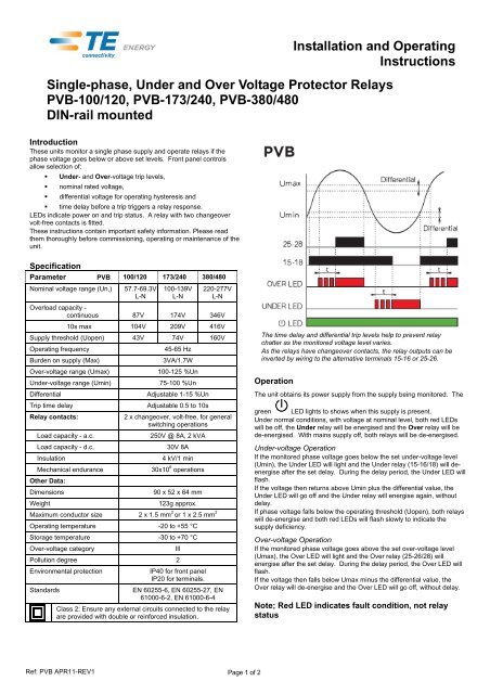
The time delay and differential trip levels help to prevent relay<br />
chatter as the monitored voltage level varies.<br />
As the relays have changeover contacts, the relay outputs can be<br />
inverted by wiring to the alternative terminals 15-16 or 25-26.<br />
Operation<br />
The unit obtains its power supply from the supply being monitored. The<br />
green LED lights to shows when this supply is present.<br />
Under normal conditions, with voltage at nominal level, both red LEDs<br />
will be off, the Under relay will be energised and the Over relay will be<br />
de-energised. With mains supply off, both relays will be de-energised.<br />
Under-voltage Operation<br />
If the monitored phase voltage goes below the set under-voltage level<br />
(Umin), the Under LED will light and the Under relay (15-16/18) will deenergise<br />
after the set delay. During the delay period, the Under LED will<br />
flash.<br />
If the voltage then returns above Umin plus the differential value, the<br />
Under LED will go off and the Under relay will energise again, without<br />
delay.<br />
If phase voltage falls below the operating threshold (Uopen), both relays<br />
will de-energise and both red LEDs will flash slowly to indicate the<br />
supply deficiency.<br />
Over-voltage Operation<br />
If the monitored phase voltage goes above the set over-voltage level<br />
(Umax), the Over LED will light and the Over relay (25-26/28) will<br />
energise after the set delay. During the delay period, the Over LED will<br />
flash.<br />
If the voltage then falls below Umax minus the differential value, the<br />
Over relay will de-energise and the Over LED will go off, without delay.<br />
Note; Red LED indicates fault condition, not relay<br />
status<br />
Ref: <strong>PVB</strong> APR11-REV1 Page 1 of 2
Installation<br />
The unit is intended for mounting on a standard DIN rail. Hook the unit<br />
onto the top of the rail and press the bottom of the unit until it locks in<br />
place. To remove the unit from the rail, lever down the black tab at the<br />
bottom of the unit to release it from the rail.<br />
The unit is intended for use in a reasonably stable ambient temperature<br />
within the range -20 to +55°C. Do not mount the unit where there is<br />
excessive vibration or in excessive direct sunlight.<br />
Safety<br />
The unit was designed in accordance with BS EN 600255-6 and -27 –<br />
Permanently connected use, Normal condition. Insulation category III,<br />
pollution degree 2, basic insulation for rated voltage. Measurement<br />
Category III.<br />
EMC Installation Requirements<br />
This unit has been designed to provide protection against EM (electromagnetic)<br />
interference in line, in accordance with BS EN 61000-6-2 and<br />
-6-4. Precautions necessary to provide proper operation of this and<br />
adjacent equipment will be installation dependent and so the following<br />
can only be general guidance:<br />
• Avoid routing wiring to this unit alongside cables and products that<br />
are, or could be, a source of interference.<br />
• To protect the product against incorrect operation or permanent<br />
damage, surge transients must be controlled. It is good EMC<br />
practice to suppress differential surges to 2kV or less at the source.<br />
The unit has been designed to automatically recover from typical<br />
transients, however in extreme circumstances it may be necessary<br />
to temporarily disconnect the auxiliary supply for a period of greater<br />
than 5 seconds to restore correct operation.<br />
• Screened communication leads are recommended and may be<br />
required. These and other connecting leads may require the fitting<br />
of RF suppression components, such as ferrite absorbers, line<br />
filters etc., if RF fields cause problems.<br />
• It is good practice to install sensitive electronic instruments that are<br />
performing critical functions in EMC enclosures that protect against<br />
electrical interference causing a disturbance in function.<br />
Warnings:<br />
NC = Normally closed. Contact closed when<br />
relay de-energised.<br />
NO = Normally open. Contact open when relay<br />
de-energised.<br />
Caution: Risk of<br />
Electric Shock<br />
• During normal operation, voltages hazardous to life may be<br />
present at some of the terminals of this unit. Installation and<br />
servicing should be performed only by qualified, properly<br />
trained personnel abiding by local regulations. Ensure all<br />
supplies are de-energised before attempting connection or<br />
other procedures.<br />
• It is recommended adjustments be made with the supplies deenergised,<br />
but if this is not possible, then extreme caution<br />
should be exercised.<br />
• Terminals should not be user accessible after installation and<br />
external installation provisions must be sufficient to prevent<br />
hazards under fault conditions.<br />
• This unit is not intended to function as part of a system<br />
providing the sole means of fault protection - good<br />
engineering practice dictates that any critical function be<br />
protected by at least two independent and diverse means.<br />
• The unit does not have internal fuses therefore external fuses<br />
must be used for protection and safety under fault conditions.<br />
• If this equipment is used in a manner not specified by the<br />
manufacturer, protection provided by the equipment may be<br />
impaired.<br />
Wiring<br />
All connections are made to screw clamp terminals. Terminals are<br />
suitable for copper wires only and will accept one stranded 0.05 -<br />
2.5mm2 (30 - 12 AWG) stranded or one solid core cables. Terminal<br />
screws should be tightened to 0.5 Nm. Choice of cable should meet local<br />
regulations. Instrument transformers used for connection to the meter<br />
must be of approved type, compliant with ANSI/IEEE C57.13 / IEC<br />
60044-1 to provide isolation from measuring inputs.<br />
For UL approved installation, use National Electrical Code (NEC) Class<br />
1 wiring, rated at 600V for main terminals, 300V auxiliary / 60°C min<br />
rating.<br />
Fusing<br />
A suitable switch or circuit breaker conforming to the relevant parts of<br />
IEC 60947-1 and IEC 60947-3 should be included in the building<br />
installation. It should be positioned so as to be easy to operate, in close<br />
proximity to the equipment, and clearly identified as the disconnecting<br />
device.<br />
This unit must be fitted with external fuses in voltage supply lines. Lines<br />
must be fused with a quick blow fuse 1A maximum. Choose fuses of a<br />
type and with a breaking capacity appropriate to the supply and in<br />
accordance with local regulations.<br />
For UL approved installations:<br />
UL listed branch circuit fuses, suitable for the installation voltage, shall<br />
be provided and installed in accordance with national installation code –<br />
1A fast acting AC rated at the inputs.<br />
Maintenance<br />
In normal use, little or no maintenance is needed. Where used, ensure<br />
any CT secondary circuits are short circuited prior to carrying out<br />
installation or maintenance of the unit. As appropriate for service<br />
conditions, isolate electrical power, inspect the unit and remove any dust<br />
or other foreign material present. Periodically check all connections for<br />
freedom from corrosion and screw tightness, particularly if vibration is<br />
present.<br />
All of the above information, including drawings, illustrations and graphic designs, reflects our present understanding and is to the best of our knowledge and belief correct<br />
and reliable. Users, however, should independently evaluate the suitability of each product for the desired application. Under no circumstances does this constitute an<br />
assurance of any particular quality or performance. Such an assurance is only provided in the context of our product specifications or explicit contractual arrangements.<br />
Our liability for these products is set forth in our standard terms and conditions of sale.<br />
TE connectivity (logo), TE (logo) and TE Connectivity are trademarks of the TE Connectivity Ltd. family of companies. CROMPTON is a trademark of <strong>Crompton</strong> Parkinson<br />
Ltd. and is used by TE Connectivity Ltd. under licence. Other logos, product and company names mentioned herein may be trademarks of their respective owners.<br />
Tyco Electronics UK Ltd.<br />
a TE Connectivity Ltd. company<br />
Freebournes Road, Witham, CM8 3AH<br />
Tel: +44 (0) 1376 509509, Fax: +44 (0) 1376 509511<br />
www.crompton-instruments.com<br />
www.energy.te.com<br />
Page 2 of 2