PROFIBUS DP STEPPER 6411-PBX - AHS Antriebstechnik GmbH
PROFIBUS DP STEPPER 6411-PBX - AHS Antriebstechnik GmbH
PROFIBUS DP STEPPER 6411-PBX - AHS Antriebstechnik GmbH

You also want an ePaper? Increase the reach of your titles
YUMPU automatically turns print PDFs into web optimized ePapers that Google loves.
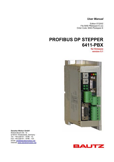
User Manual<br />
Edition 07/2002<br />
File MAE-PBstepper-E.xxx<br />
Order Code: MAE-Pbstepper-E<br />
<strong>PROFIBUS</strong> <strong>DP</strong> <strong>STEPPER</strong><br />
<strong>6411</strong>-<strong>PBX</strong><br />
for firmware<br />
version 5.1<br />
Danaher Motion <strong>GmbH</strong><br />
Robert-Bosch-Str. 10<br />
D-64331 Weiterstadt, Germany<br />
Tel.: +49 (0)6151 - 8796 - 10<br />
Fax: +49 (0)6151 - 8796 - 123<br />
Email: info@danahermotion.net<br />
Internet: www.danahermotion.net
<strong>PROFIBUS</strong> <strong>DP</strong> <strong>STEPPER</strong> 07/2002 BAUTZ<br />
Trademarks used:<br />
IBM and PC-AT are registered trademarks of International Business Machines Corp.<br />
Simatic S5 is a registered trademark of Siemens AG.<br />
This document is protected by copyright.<br />
(Copyright 2002, Danaher Motion <strong>GmbH</strong>).<br />
Danaher Motion <strong>GmbH</strong> reserves the right to make changes that serve to improve the quality of the product<br />
described in this manual without prior notice. The authors will be pleased to receive any comments with<br />
regard to errors, contradictions or clarity.<br />
2 User Manual
BAUTZ 07/2002 <strong>PROFIBUS</strong> <strong>DP</strong> <strong>STEPPER</strong><br />
Contents<br />
1. General .................................................................................................................................................. 4<br />
2. Hardware arrangement ........................................................................................................................ 5<br />
3. Configuration of the <strong>PROFIBUS</strong> <strong>DP</strong> address.....................................................................................6<br />
4. Handling ................................................................................................................................................ 7<br />
5. Diagnosis LED and alarm status....................................................................................................... 11<br />
6. Programming the PBS stepper motor controller ............................................................................ 12<br />
6.1 Structure of the command word and the acceleration code................................................... 13<br />
6.2 Layout of the status word........................................................................................................... 15<br />
6.3 Setting the value for the velocity code ..................................................................................... 16<br />
6.4 Positioning................................................................................................................................... 19<br />
6.5 Use of the target position........................................................................................................... 20<br />
7. Command examples........................................................................................................................... 21<br />
8. Start Homing ....................................................................................................................................... 25<br />
9. Emergency stop function .................................................................................................................. 28<br />
Attachment A – Housing dimensions................................................................................................... 29<br />
User Manual 3
<strong>PROFIBUS</strong> <strong>DP</strong> <strong>STEPPER</strong> 07/2002 BAUTZ<br />
1. General<br />
If you need to control several stepper motor drives in a distributed field application via <strong>PROFIBUS</strong>-<strong>DP</strong>, then<br />
the <strong>DP</strong> <strong>STEPPER</strong> is the answer. The <strong>DP</strong> <strong>STEPPER</strong> is a compact single-axis positioning control, with an<br />
integrated output stage for driving a stepper motor. It includes two limit switches, one stop switch (interrupt<br />
input) and one reference switch. Eight input and output bytes respectively are sufficient to control the<br />
<strong>STEPPER</strong> via <strong>PROFIBUS</strong> <strong>DP</strong> for handling single-axis positioning tasks. As the system only makes use of the<br />
process data channel, the <strong>STEPPER</strong> can be integrated into any control system that uses <strong>PROFIBUS</strong> <strong>DP</strong> as a<br />
sensor/actuator bus, without additional expenditure for installation. The fast, simultaneous transmission of the<br />
input and output bytes for all devices (participants) in the <strong>PROFIBUS</strong> <strong>DP</strong> system opens up numerous options<br />
for implementing multi-axis drives across the bus system, without having to put up with synchronization -<br />
problems.<br />
The drive cycle time can be flexibly adjusted by the control system, even while the drive is running. It is also<br />
possible to enter an acceleration up to a final limit or select a target position, again while the drive is running.<br />
All status variables can be read in from the control system as two input bytes. Positioning tasks can therefore<br />
be implemented with the <strong>STEPPER</strong> in a very flexible way. And, for special applications, it is also possible to<br />
implement customer-specific functions in the <strong>STEPPER</strong> hardware in a fast, economic solution.<br />
4 User Manual
BAUTZ 07/2002 <strong>PROFIBUS</strong> <strong>DP</strong> <strong>STEPPER</strong><br />
2. Hardware arrangement<br />
The block diagram below shows the arrangement of the <strong>STEPPER</strong> hardware:<br />
Position and function of connections<br />
Not used<br />
<strong>PROFIBUS</strong><br />
address<br />
Status LEDs<br />
Stepper inputs<br />
Supply connection<br />
<strong>PROFIBUS</strong> connection<br />
Assignments:<br />
3/8 : Data B / Data A<br />
5 : DGND<br />
6 : VP<br />
Motor connection<br />
User Manual 5
<strong>PROFIBUS</strong> <strong>DP</strong> <strong>STEPPER</strong> 07/2002 BAUTZ<br />
3. Configuration of the <strong>PROFIBUS</strong> <strong>DP</strong> address<br />
The <strong>PROFIBUS</strong> address is set manually, using two rotary switches. The valid range for the <strong>PROFIBUS</strong> <strong>DP</strong><br />
address is: 1-126<br />
<strong>PROFIBUS</strong> address:<br />
Low nibble (00h-09h)<br />
<strong>PROFIBUS</strong> address:<br />
High nibble (00h-0Ch)<br />
Examples of <strong>PROFIBUS</strong> addresses:<br />
Address High nibble Address Low nibble <strong>PROFIBUS</strong> address<br />
Hex Decimal Hex Decimal Decimal<br />
00 00 08 8 008<br />
03 03 00 0 030<br />
09 09 05 5 095<br />
0A 10 03 3 103<br />
0C 12 06 6 126<br />
6 User Manual
BAUTZ 07/2002 <strong>PROFIBUS</strong> <strong>DP</strong> <strong>STEPPER</strong><br />
4. Handling<br />
The <strong>DP</strong> Stepper is fitted with a fieldbus connection for <strong>PROFIBUS</strong> <strong>DP</strong>, and is integrated into <strong>PROFIBUS</strong> <strong>DP</strong><br />
as a bus-system device. Inputs and outputs are electrically isolated from the control electronics, and run off<br />
an external 24 V DC supply. The homing (reference) run and all settings are completely set up via the<br />
<strong>PROFIBUS</strong> <strong>DP</strong> interface, and can be altered through the bus during operation. One output is assigned to the<br />
busy signal, so that electrical interlock functions can be implemented while the drive is running.<br />
As seen by <strong>PROFIBUS</strong> <strong>DP</strong>, the <strong>STEPPER</strong> behaves as a device with eight input bytes and twelve output<br />
bytes. The control system can start or change drive actions by setting various bits in the command word<br />
(output bytes 7 + 8).<br />
The control system can obtain the present status and actual position at any time, by simply reading the input<br />
bytes 3 – 8.<br />
The absolute target position, to which the stepper should run after the next Motor Start command, is entered<br />
in output bytes 5 – 8. This target position can also be altered while the drive is moving. In this way, exact<br />
positioning can be performed without additional loading of the <strong>PROFIBUS</strong> <strong>DP</strong> master.<br />
12 output bytes:<br />
Byte no.<br />
1+2<br />
Meaning<br />
Velocity code:<br />
Set velocity, for normal movement.<br />
Set target velocity, for acceleration movement.<br />
3+4 Initial velocity (for acceleration movement)<br />
5+6 Acceleration code, consisting of time unit and value division<br />
7+8 Command word<br />
9+10 Set target position, Low word<br />
11+12 Set target position, High word<br />
User Manual 7
<strong>PROFIBUS</strong> <strong>DP</strong> <strong>STEPPER</strong> 07/2002 BAUTZ<br />
8 input bytes:<br />
Byte no.<br />
Meaning<br />
1+2 Display the present velocity<br />
3+4 Status bytes<br />
5+6 Actual position, Low word<br />
7+8 Actual position, High word<br />
Connection of the inputs and outputs<br />
8 In-Bytes<br />
12 Out-Bytes<br />
8 User Manual
BAUTZ 07/2002 <strong>PROFIBUS</strong> <strong>DP</strong> <strong>STEPPER</strong><br />
Input connections<br />
Schematic layout of a drive axis for the <strong>STEPPER</strong><br />
List of inputs and outputs<br />
Upper limit switch (break contact) -------- Input 2<br />
Lower limit switch (break contact) -------- Input 4<br />
Reference point (make contact) ---------- Input 3<br />
Stop (make or break contact)-------------- Input 1<br />
User Manual 9
<strong>PROFIBUS</strong> <strong>DP</strong> <strong>STEPPER</strong> 07/2002 BAUTZ<br />
Assignment of the inputs<br />
Stop (interrupt) switch<br />
(24V DC input)<br />
Limit switch E1 (24V DC input)<br />
Reference switch (24V DC<br />
input)<br />
Limit switch E2 (24V DC input)<br />
Input GND (24V DC)<br />
10 User Manual
BAUTZ 07/2002 <strong>PROFIBUS</strong> <strong>DP</strong> <strong>STEPPER</strong><br />
5. Diagnosis LED and alarm status<br />
A diagnosis LED is provided, to provide an at-a-glance check that the module processor is functioning<br />
correctly. The diagnosis LED flashes at a frequency of 5Hz.<br />
! Alarm status !<br />
As soon as the stepper switches on the alarm status, the diagnosis LED indicates this by lighting up<br />
continuously. The alarm status can be triggered by the following events:<br />
1. The lower limit switch was activated during a homing run. (see section 8)<br />
2. There is a processor fault.<br />
No commands can be carried out while the alarm status is present. The stepper blocks off all PBS command<br />
information. However, PBS input information (i.e. status information and position signaling) will still be<br />
reported. The status information will now include the Alarm status active message.<br />
! Terminate alarm status !<br />
The stepper has been fitted with an option for terminating the alarm status without having to switch off the<br />
module. This is achieved by introducing a pseudo-code for the PBS output bytes 1+2 (velocity code). The<br />
code used is 0xAA55. This code does not occur in normal operation, since the code for the maximum<br />
velocity is 0x1FF. If the stepper reads this pseudo-code, then it checks again whether the conditions for the<br />
alarm status are still present. If these conditions are no longer present, then it switches off the alarm status<br />
and returns to the operational condition after the pseudo-code has terminated. The diagnosis LED starts to<br />
flash again, indicating the operating condition. Please note that the output of the pseudo-code 0xAA55 must<br />
have really stopped in order for the normal operating condition to be resumed.<br />
! Activate/deactivate control switches !<br />
Entering the word 8001h in the velocity code activates the control switches. Entering 8000h deactivates the<br />
control switches.<br />
Standard setting: Control switches activated.<br />
Interpretation of the status LEDs<br />
<strong>PROFIBUS</strong> active<br />
5V supply o.k.<br />
Stepper status<br />
(activity)<br />
Stepper busy<br />
User Manual 11
<strong>PROFIBUS</strong> <strong>DP</strong> <strong>STEPPER</strong> 07/2002 BAUTZ<br />
6. Programming the PBS stepper motor controller<br />
The PBS stepper motor controller is controlled and monitored by eight input and eight output bytes, via<br />
<strong>PROFIBUS</strong> <strong>DP</strong>. The I/O bytes are assigned as follows:<br />
12 output bytes<br />
Byte no.<br />
1+2<br />
3+4<br />
5+6<br />
7+8<br />
9+10<br />
11+12<br />
Meaning<br />
Velocity code:<br />
Set velocity, for normal movement.<br />
Set target velocity, for acceleration movement.<br />
Byte 1: High byte; Byte 2 Low byte<br />
Start velocity, for acceleration movement.<br />
Byte 3: High byte; Byte 4 Low byte<br />
Acceleration code, consisting of time unit and value division<br />
Byte 5: Time unit ; Byte 6: Value division<br />
Command word<br />
Byte7: High byte; Byte 8 Low byte Low byte<br />
Set target position, Low word<br />
Byte 9: High byte; Byte 10 Low byte<br />
Set target position, High word<br />
Byte 11: High byte; Byte 12 Low byte<br />
The Time step in the acceleration code defines (how many) x 1 millisecond the drive should remain at a<br />
frequency step during the ramp time. The value division defines that one in every (value division) values from<br />
the table on Page 16 is to be used to generate the ramp(s). A detailed description of both of these<br />
parameters can be found on Page 14.<br />
8 input bytes<br />
Byte no.<br />
1+2<br />
3+4<br />
5+6<br />
7+8<br />
Meaning<br />
Display the present velocity<br />
Byte 1: High byte; Byte 2 Low byte Low byte<br />
Status bytes<br />
Byte 3: High byte; Byte 4 Low byte<br />
Actual position, low word<br />
Byte 5: High byte; Byte 6 Low byte<br />
Actual position, high word<br />
Byte 7: High byte; Byte 8 Low byte<br />
12 User Manual
BAUTZ 07/2002 <strong>PROFIBUS</strong> <strong>DP</strong> <strong>STEPPER</strong><br />
6.1 Structure of the command word and the acceleration code<br />
In order to get the stepper motor to carry out an action, the control system must set the corresponding bits in<br />
the Command word. Nine bits are transmitted to the stepper motor controller for the transfer of commands.<br />
The bits in the command word have the following meaning:<br />
Bits Byte Meaning Range of values<br />
00 Reserve<br />
01 Counter reset<br />
02 Acceleration on/off<br />
03<br />
8<br />
Velocity mode<br />
04 Motor start/stop<br />
05 Direction of motion<br />
06 Enable output<br />
07<br />
Homing<br />
08 Default rot. direction<br />
09 Polarity of stop switch<br />
10...15<br />
7<br />
Reserve<br />
0 = counter active<br />
1 = counter reset (to 8000 0000h)<br />
0 = acceleration off (normal movement)<br />
1 = acceleration on (acceleration movement)<br />
0 = position mode<br />
1 = velocity mode<br />
0 = stop motor/initialize command<br />
1 = start motor<br />
0 = forwards<br />
1 = backwards<br />
0 = off<br />
1 = on<br />
0 = normal mode<br />
1 = homing (move to reference point)<br />
0 = default direction of rotation as defined by Bit 05<br />
1 = default direction of rotation, defined by inverted Bit 05<br />
0 = normal / break contact<br />
1 = inverse / make contact<br />
Bit<br />
1<br />
2<br />
3<br />
4<br />
5<br />
6<br />
7<br />
8<br />
9<br />
Description<br />
If this bit is set to 1, the step counter is reset to 8000 0000h in the input bytes 5-8. This bit must<br />
always be set to 0 for the normal positioning mode. The enable (Bit4) is ineffective as long as this bit<br />
is set<br />
If this bit is set to 1, the acceleration mode of the stepper is activated, i.e. the selected final velocity is<br />
not reached instantly, but with some delay as a result of the acceleration that is defined in the<br />
acceleration code. If this bit is 0, the chosen step velocity is produced at once.<br />
If this bit is set to 1, the stepper is operated in the velocity mode with an open-loop speed setpoint. No<br />
limit switches, stop switches or position setpoints will be evaluated. This bit must be set to 0 for<br />
normal positioning operation.<br />
Setting this bit to 0 stops a motion command that is being performed. The transition from 0 to 1<br />
enables the motor, and starts the corresponding motion command. When the motion command is<br />
finished, this bit must be set to 0 again.<br />
This bit controls the direction of motion, i.e. the output direction of the stepper.<br />
The effect of Bit 8, which determines the default direction, must also be taken into account.<br />
This bit is applied directly to the enable output of the stepper, and can be used to enable a group of<br />
stepper motors.<br />
If this bit is set to 1, the normal mode of operation of the stepper is de-activated, and a homing run<br />
(movement to the reference point) is started. Homing is described in detail in Chapter 8.<br />
This determines whether Bit 5 is evaluated normally or with inverse polarity.<br />
If Bit 8 = 0 then, for Bit 5, 0 = backwards and 1 = forwards. If Bit 8 = 1, then the opposite applies.<br />
This bit determines the polarity of the stop input: 0 = break contact, 1 = make contact<br />
User Manual 13
<strong>PROFIBUS</strong> <strong>DP</strong> <strong>STEPPER</strong> 07/2002 BAUTZ<br />
Detailed make-up of the acceleration code<br />
Bit15... Acceleration time step D7<br />
Bit14... Acceleration time step D6<br />
Bit13... Acceleration time step D5<br />
Bit12... Acceleration time step D4<br />
Bit11... Acceleration time step D3<br />
Bit10... Acceleration time step D2<br />
Bit09... Acceleration time step D1<br />
Bit08... Acceleration time step D0<br />
Bit07... Acceleration value division D7<br />
Bit06... Acceleration value division D6<br />
Bit05... Acceleration value division D5<br />
Bit04... Acceleration value division D4<br />
Bit03... Acceleration value division D3<br />
Bit02... Acceleration value division D2<br />
Bit01... Acceleration value division D1<br />
Bit00... Acceleration value division D0<br />
All details on the initial and final velocities in the examples refer to the coding as given in the table starting on<br />
Page 16:<br />
Example 1<br />
Example 2<br />
Example 3<br />
Given values: - initial velocity: 0<br />
- final velocity: 535<br />
- acceleration time step: 1<br />
- acceleration value division: 10<br />
Calculation: - internal index table:<br />
0,10,20,30,40,50,60,70,80,90,100,110,120,130,140,150,160,170,180,<br />
190,200,210,220,230,240,250,260,270,280,290,300,310,320,330,<br />
340,350,360,370,380,390,400,410,420,430,440,450,460,470,480,<br />
490,500,510,520, 520,530,535<br />
- total time taken to reach the final velocity: 54 msec<br />
Given values: - initial velocity: 10<br />
- final velocity: 50<br />
- acceleration time step: 5<br />
- acceleration value division: 1<br />
Calculation: - internal index table:<br />
10,11,12,13,14,15,16,17,18,19,20,21,22,23,24,25,26,27,28,29,30,<br />
31,32,33,34,35,36,37,38,39,40,41,42,43,44,45,46,47,48,49,50<br />
- total time taken to reach the final velocity: 200 msec<br />
Given values: - initial velocity: 10<br />
- final velocity: 535<br />
- acceleration time step: 1<br />
- acceleration value division: 52<br />
Calculation: - internal index table:<br />
10,63,116,169,222,275,328,381,434,487,535<br />
- total time taken to reach the final velocity<br />
14 User Manual
BAUTZ 07/2002 <strong>PROFIBUS</strong> <strong>DP</strong> <strong>STEPPER</strong><br />
6.2 Layout of the status word<br />
In order to be able to transfer the present status of the stepper motor controller to the control system, the<br />
status bytes (input bytes 3+4) of the controller must be read. The table below shows how the bits within the<br />
status byte can be evaluated to determine the present status of the stepper controller.<br />
Bits 0-7 = input byte 3, and Bits 8-15 = input byte 4 have the following meanings:<br />
Bits Byte Meaning Range of values<br />
0 Stop switch status<br />
1 Lower limit switch status<br />
2 Reference point switch status<br />
3 4 Upper limit switch status<br />
4 Present direction of motion<br />
5 Limit velocity status<br />
6 not assigned<br />
7<br />
Busy indication<br />
8 Limit switch status<br />
9<br />
10<br />
Logic level of upper limit switch<br />
Logic level of lower limit switch<br />
11 Emergency stop / alarm<br />
3<br />
12 Counter status<br />
13 not assigned<br />
14 Module error<br />
15<br />
not assigned<br />
0 = stop switch not activated<br />
1 = stop switch activated<br />
0 = limit switch not activated<br />
1 = limit switch activated<br />
0 = reference point switch is open<br />
1 = reference point switch is closed<br />
0 = limit switch not activated<br />
1 = limit switch activated<br />
0 = forwards (COUNT is incremented)<br />
1 = backwards (COUNT is decremented)<br />
0 = limit velocity not yet reached<br />
1 = limit velocity reached<br />
0 = step output is static (busy)<br />
1 = step output is running<br />
0 = no limit switch reached<br />
1 = a limit switch has been reached<br />
0 = all o.k.<br />
1 = alarm or emergency stop activated<br />
0 = data are invalid<br />
1 = counter data are valid<br />
0 = module o.k.<br />
1 = module error<br />
User Manual 15
<strong>PROFIBUS</strong> <strong>DP</strong> <strong>STEPPER</strong> 07/2002 BAUTZ<br />
6.3 Setting the value for the velocity code<br />
The velocity code is contained in the first two output bytes. The possible range of values is from 000h to<br />
32Bh. The stepper uses an internally stored table to interpret the velocity code. This contains 811 integer<br />
values that encode the direct timer constants for the step clock rate.<br />
The difference between one velocity value and the next is 15Hz for rates below 10kHz, and 30Hz for rates<br />
above 10 kHz. The nature of the timer structure in the processor means that the relationship is not perfectly<br />
linear. The exact values can be taken from the following table.<br />
For special applications, it is possible to create a new code table and store it in the processor.<br />
This table also applies for the initial velocity.<br />
Code Frequency (Hz)<br />
0 30<br />
1 45<br />
2 60<br />
3 75<br />
4 90<br />
5 105<br />
6 120<br />
7 135<br />
8 150<br />
9 165<br />
A 180<br />
B 195<br />
C 210<br />
D 225<br />
E 240<br />
F 255<br />
10 270<br />
11 285<br />
12 300<br />
13 315<br />
14 330<br />
15 345<br />
16 360<br />
17 375<br />
18 390<br />
19 405<br />
1A 420<br />
1B 435<br />
1C 450<br />
1D 465<br />
1E 480<br />
1F 495<br />
20 510<br />
21 525<br />
22 540<br />
23 555<br />
24 570<br />
25 585<br />
26 600<br />
27 615<br />
28 630<br />
29 645<br />
2A 660<br />
2B 675<br />
2C 690<br />
2D 705<br />
2E 720<br />
2F 735<br />
30 750<br />
31 765<br />
32 780<br />
33 795<br />
34 810<br />
Code Frequency (Hz)<br />
35 825<br />
36 840<br />
37 855<br />
38 870<br />
39 885<br />
3A 900<br />
3B 915<br />
3C 930<br />
3D 945<br />
3E 960<br />
3F 975<br />
40 990<br />
41 1005<br />
42 1020<br />
43 1035<br />
44 1050<br />
45 1065<br />
46 1080<br />
47 1095<br />
48 1110<br />
49 1125<br />
4A 1140<br />
4B 1155<br />
4C 1170<br />
4D 1185<br />
4E 1200<br />
4F 1215<br />
50 1230<br />
51 1245<br />
52 1260<br />
53 1275<br />
54 1290<br />
55 1305<br />
56 1320<br />
57 1335<br />
58 1350<br />
59 1365<br />
5A 1380<br />
5B 1395<br />
5C 1410<br />
5D 1425<br />
5E 1440<br />
5F 1455<br />
60 1470<br />
61 1485<br />
62 1500<br />
63 1515<br />
64 1530<br />
65 1545<br />
66 1560<br />
67 1575<br />
68 1590<br />
69 1605<br />
Code Frequency (Hz)<br />
6A 1620<br />
6B 1635<br />
6C 1650<br />
6D 1665<br />
6E 1680<br />
6F 1695<br />
70 1710<br />
71 1725<br />
72 1740<br />
73 1755<br />
74 1770<br />
75 1785<br />
76 1800<br />
77 1815<br />
78 1830<br />
79 1845<br />
7A 1860<br />
7B 1875<br />
7C 1890<br />
7D 1905<br />
7E 1920<br />
7F 1935<br />
80 1950<br />
81 1965<br />
82 1980<br />
83 1995<br />
84 2010<br />
85 2025<br />
86 2040<br />
87 2055<br />
88 2070<br />
89 2085<br />
8A 2100<br />
8B 2115<br />
8C 2130<br />
8D 2145<br />
8E 2160<br />
8F 2175<br />
90 2190<br />
91 2205<br />
92 2220<br />
93 2235<br />
94 2250<br />
95 2265<br />
96 2280<br />
97 2295<br />
98 2310<br />
99 2325<br />
9A 2340<br />
9B 2355<br />
9C 2370<br />
9D 2385<br />
9E 2400<br />
Code Frequency (Hz)<br />
9F 2415<br />
A0 2430<br />
A1 2445<br />
A2 2460<br />
A3 2475<br />
A4 2490<br />
A5 2505<br />
A6 2521<br />
A7 2536<br />
A8 2551<br />
A9 2566<br />
AA 2581<br />
AB 2596<br />
AC 2612<br />
AD 2628<br />
AE 2643<br />
AF 2658<br />
B0 2673<br />
B1 2688<br />
B2 2703<br />
B3 2718<br />
B4 2733<br />
B5 2748<br />
B6 2763<br />
B7 2779<br />
B8 2794<br />
B9 2810<br />
BA 2826<br />
BB 2842<br />
BC 2857<br />
BD 2872<br />
BE 2887<br />
BF 2902<br />
C0 2918<br />
C1 2933<br />
C2 2948<br />
C3 2964<br />
C4 2979<br />
C5 2994<br />
C6 3009<br />
C7 3024<br />
C8 3039<br />
C9 3054<br />
CA 3069<br />
CB 3084<br />
CC 3099<br />
CD 3115<br />
CE 3131<br />
CF 3146<br />
D0 3161<br />
D1 3176<br />
D2 3191<br />
D3 3206<br />
Code Frequency (Hz)<br />
D4 3222<br />
D5 3237<br />
D6 3252<br />
D7 3267<br />
D8 3282<br />
D9 3298<br />
DA 3313<br />
DB 3329<br />
DC 3344<br />
DD 3359<br />
DE 3374<br />
DF 3389<br />
E0 3405<br />
E1 3420<br />
E2 3436<br />
E3 3452<br />
E4 3468<br />
E5 3484<br />
E6 3500<br />
E7 3516<br />
E8 3531<br />
E9 3546<br />
EA 3562<br />
EB 3577<br />
EC 3592<br />
ED 3607<br />
EE 3623<br />
EF 3638<br />
F0 3654<br />
F1 3669<br />
F2 3685<br />
F3 3701<br />
F4 3717<br />
F5 3733<br />
F6 3750<br />
F7 3766<br />
F8 3783<br />
F9 3799<br />
FA 3814<br />
FB 3831<br />
FC 3846<br />
FD 3861<br />
FE 3878<br />
FF 3893<br />
100 3908<br />
101 3924<br />
102 3939<br />
103 3955<br />
104 3970<br />
105 3986<br />
106 4002<br />
107 4018<br />
108 4034<br />
16 User Manual
BAUTZ 07/2002 <strong>PROFIBUS</strong> <strong>DP</strong> <strong>STEPPER</strong><br />
Code Frequency (Hz)<br />
109 4051<br />
10A 4067<br />
10B 4084<br />
10C 4101<br />
10D 4118<br />
10E 4135<br />
10F 4152<br />
110 4169<br />
111 4184<br />
112 4201<br />
113 4216<br />
114 4231<br />
115 4246<br />
116 4261<br />
117 4276<br />
118 4291<br />
119 4307<br />
11A 4322<br />
11B 4338<br />
11C 4354<br />
11D 4369<br />
11E 4385<br />
11F 4402<br />
120 4418<br />
121 4434<br />
122 4451<br />
123 4467<br />
124 4484<br />
125 4501<br />
126 4518<br />
127 4535<br />
128 4552<br />
129 4569<br />
12A 4587<br />
12B 4604<br />
12C 4622<br />
12D 4640<br />
12E 4658<br />
12F 4676<br />
130 4691<br />
131 4709<br />
132 4724<br />
133 4739<br />
134 4754<br />
135 4769<br />
136 4784<br />
137 4800<br />
138 4815<br />
139 4830<br />
13A 4846<br />
13B 4862<br />
13C 4878<br />
13D 4893<br />
13E 4909<br />
13F 4926<br />
140 4942<br />
141 4958<br />
142 4975<br />
143 4991<br />
144 5008<br />
145 5025<br />
146 5042<br />
147 5059<br />
148 5076<br />
149 5093<br />
14A 5110<br />
14B 5128<br />
Code Frequency (Hz)<br />
14C 5145<br />
14D 5163<br />
14E 5181<br />
14F 5199<br />
150 5217<br />
151 5235<br />
152 5253<br />
153 5272<br />
154 5291<br />
155 5309<br />
156 5328<br />
157 5347<br />
158 5366<br />
159 5381<br />
15A 5400<br />
15B 5415<br />
15C 5434<br />
15D 5449<br />
15E 5464<br />
15F 5479<br />
160 5494<br />
161 5509<br />
162 5524<br />
163 5540<br />
164 5555<br />
165 5571<br />
166 5586<br />
167 5602<br />
168 5617<br />
169 5633<br />
16A 5649<br />
16B 5665<br />
16C 5681<br />
16D 5698<br />
16E 5714<br />
16F 5730<br />
170 5747<br />
171 5763<br />
172 5780<br />
173 5797<br />
174 5813<br />
175 5830<br />
176 5847<br />
177 5865<br />
178 5882<br />
179 5899<br />
17A 5917<br />
17B 5934<br />
17C 5952<br />
17D 5970<br />
17E 5988<br />
17F 6006<br />
180 6024<br />
181 6042<br />
182 6060<br />
183 6079<br />
184 6097<br />
185 6116<br />
186 6134<br />
187 6153<br />
188 6172<br />
189 6191<br />
18A 6211<br />
18B 6230<br />
18C 6250<br />
18D 6269<br />
18E 6289<br />
Code Frequency (Hz)<br />
18F 6309<br />
190 6329<br />
191 6349<br />
192 6369<br />
193 6389<br />
194 6410<br />
195 6430<br />
196 6451<br />
197 6472<br />
198 6493<br />
199 6514<br />
19A 6535<br />
19B 6550<br />
19C 6571<br />
19D 6586<br />
19E 6607<br />
19F 6622<br />
1A0 6637<br />
1A1 6659<br />
1A2 6674<br />
1A3 6696<br />
1A4 6711<br />
1A5 6726<br />
1A6 6741<br />
1A7 6756<br />
1A8 6772<br />
1A9 6787<br />
1AA 6802<br />
1AB 6818<br />
1AC 6833<br />
1AD 6849<br />
1AE 6864<br />
1AF 6880<br />
1B0 6896<br />
1B1 6912<br />
1B2 6928<br />
1B3 6944<br />
1B4 6960<br />
1B5 6976<br />
1B6 6993<br />
1B7 7009<br />
1B8 7025<br />
1B9 7042<br />
1BA 7058<br />
1BB 7075<br />
1BC 7092<br />
1BD 7109<br />
1BE 7125<br />
1BF 7142<br />
1C0 7159<br />
1C1 7177<br />
1C2 7194<br />
1C3 7211<br />
1C4 7228<br />
1C5 7246<br />
1C6 7263<br />
1C7 7281<br />
1C8 7299<br />
1C9 7317<br />
1CA 7334<br />
1CB 7352<br />
1CC 7371<br />
1CD 7389<br />
1CE 7407<br />
1CF 7425<br />
1D0 7444<br />
1D1 7462<br />
Code Frequency (Hz)<br />
1D2 7481<br />
1D3 7500<br />
1D4 7518<br />
1D5 7537<br />
1D6 7556<br />
1D7 7575<br />
1D8 7594<br />
1D9 7614<br />
1DA 7633<br />
1DB 7653<br />
1DC 7672<br />
1DD 7692<br />
1DE 7712<br />
1DF 7731<br />
1E0 7751<br />
1E1 7772<br />
1E2 7792<br />
1E3 7812<br />
1E4 7832<br />
1E5 7853<br />
1E6 7874<br />
1E7 7894<br />
1E8 7915<br />
1E9 7936<br />
1EA 7957<br />
1EB 7978<br />
1EC 8000<br />
1ED 8021<br />
1EE 8042<br />
1EF 8064<br />
1F0 8086<br />
1F1 8108<br />
1F2 8130<br />
1F3 8152<br />
1F4 8174<br />
1F5 8196<br />
1F6 8219<br />
1F7 8241<br />
1F8 8264<br />
1F9 8287<br />
1FA 8310<br />
1FB 8333<br />
1FC 8356<br />
1FD 8379<br />
1FE 8403<br />
1FF 8426<br />
200 8450<br />
201 8474<br />
202 8498<br />
203 8522<br />
204 8547<br />
205 8571<br />
206 8595<br />
207 8620<br />
208 8645<br />
209 8670<br />
20A 8695<br />
20B 8720<br />
20C 8746<br />
20D 8771<br />
20E 8797<br />
20F 8823<br />
210 8849<br />
211 8875<br />
212 8902<br />
213 8928<br />
214 8955<br />
Code Frequency (Hz)<br />
215 8982<br />
216 9009<br />
217 9036<br />
218 9063<br />
219 9090<br />
21A 9118<br />
21B 9146<br />
21C 9174<br />
21D 9202<br />
21E 9230<br />
21F 9259<br />
220 9287<br />
221 9302<br />
222 9331<br />
223 9360<br />
224 9375<br />
225 9404<br />
226 9419<br />
227 9448<br />
228 9463<br />
229 9478<br />
22A 9493<br />
22B 9508<br />
22C 9523<br />
22D 9538<br />
22E 9554<br />
22F 9569<br />
230 9584<br />
231 9600<br />
232 9615<br />
233 9630<br />
234 9646<br />
235 9661<br />
236 9677<br />
237 9693<br />
238 9708<br />
239 9724<br />
23A 9740<br />
23B 9756<br />
23C 9771<br />
23D 9787<br />
23E 9803<br />
23F 9819<br />
240 9836<br />
241 9852<br />
242 9868<br />
243 9884<br />
244 9900<br />
245 9917<br />
246 9933<br />
247 9950<br />
248 9966<br />
249 9983<br />
24A 10000<br />
24B 10016<br />
24C 10050<br />
24D 10084<br />
24E 10118<br />
24F 10152<br />
250 10186<br />
251 10221<br />
252 10256<br />
253 10291<br />
254 10327<br />
255 10362<br />
256 10398<br />
257 10434<br />
User Manual 17
<strong>PROFIBUS</strong> <strong>DP</strong> <strong>STEPPER</strong> 07/2002 BAUTZ<br />
Code Frequency (Hz)<br />
258 10471<br />
259 10507<br />
25A 10544<br />
25B 10582<br />
25C 10619<br />
25D 10657<br />
25E 10695<br />
25F 10733<br />
260 10771<br />
261 10810<br />
262 10849<br />
263 10889<br />
264 10928<br />
265 10968<br />
266 11009<br />
267 11049<br />
268 11090<br />
269 11131<br />
26A 11173<br />
26B 11214<br />
26C 11257<br />
26D 11299<br />
26E 11342<br />
26F 11385<br />
270 11428<br />
271 11472<br />
272 11516<br />
273 11560<br />
274 11605<br />
275 11650<br />
276 11695<br />
277 11741<br />
278 11787<br />
279 11834<br />
27A 11881<br />
27B 11928<br />
27C 11976<br />
27D 12024<br />
27E 12072<br />
27F 12121<br />
280 12170<br />
281 12219<br />
282 12269<br />
Code Frequency (Hz)<br />
283 12320<br />
284 12371<br />
285 12422<br />
286 12474<br />
287 12526<br />
288 12578<br />
289 12631<br />
28A 12684<br />
28B 12738<br />
28C 12793<br />
28D 12847<br />
28E 12903<br />
28F 12958<br />
290 13015<br />
291 13071<br />
292 13129<br />
293 13186<br />
294 13245<br />
295 13303<br />
296 13333<br />
297 13363<br />
298 13422<br />
299 13452<br />
29A 13483<br />
29B 13513<br />
29C 13544<br />
29D 13574<br />
29E 13605<br />
29F 13636<br />
2A0 13667<br />
2A1 13698<br />
2A2 13729<br />
2A3 13761<br />
2A4 13793<br />
2A5 13824<br />
2A6 13856<br />
2A7 13888<br />
2A8 13921<br />
2A9 13953<br />
2AA 13986<br />
2AB 14018<br />
2AC 14051<br />
2AD 14084<br />
Code Frequency (Hz)<br />
2AE 14117<br />
2AF 14150<br />
2B0 14184<br />
2B1 14218<br />
2B2 14251<br />
2B3 14285<br />
2B4 14319<br />
2B5 14354<br />
2B6 14388<br />
2B7 14423<br />
2B8 14457<br />
2B9 14492<br />
2BA 14527<br />
2BB 14563<br />
2BC 14598<br />
2BD 14634<br />
2BE 14669<br />
2BF 14705<br />
2C0 14742<br />
2C1 14778<br />
2C2 14814<br />
2C3 14851<br />
2C4 14888<br />
2C5 14925<br />
2C6 14962<br />
2C7 15000<br />
2C8 15037<br />
2C9 15075<br />
2CA 15113<br />
2CB 15151<br />
2CC 15189<br />
2CD 15228<br />
2CE 15267<br />
2CF 15306<br />
2D0 15345<br />
2D1 15384<br />
2D2 15424<br />
2D3 15463<br />
2D4 15503<br />
2D5 15544<br />
2D6 15584<br />
2D7 15625<br />
2D8 15665<br />
Code Frequency (Hz)<br />
2D9 15706<br />
2DA 15748<br />
2DB 15789<br />
2DC 15831<br />
2DD 15873<br />
2DE 15915<br />
2DF 15957<br />
2E0 16000<br />
2E1 16042<br />
2E2 16085<br />
2E3 16129<br />
2E4 16172<br />
2E5 16216<br />
2E6 16260<br />
2E7 16304<br />
2E8 16348<br />
2E9 16393<br />
2EA 16438<br />
2EB 16483<br />
2EC 16528<br />
2ED 16574<br />
2EE 16620<br />
2EF 16666<br />
2F0 16713<br />
2F1 16759<br />
2F2 16806<br />
2F3 16853<br />
2F4 16901<br />
2F5 16949<br />
2F6 16997<br />
2F7 17045<br />
2F8 17094<br />
2F9 17142<br />
2FA 17191<br />
2FB 17241<br />
2FC 17291<br />
2FD 17341<br />
2FE 17391<br />
2FF 17441<br />
300 17492<br />
301 17543<br />
302 17595<br />
303 17647<br />
Code Frequency (Hz)<br />
304 17699<br />
305 17751<br />
306 17804<br />
307 17857<br />
308 17910<br />
309 17964<br />
30A 18018<br />
30B 18072<br />
30C 18126<br />
30D 18181<br />
30E 18237<br />
30F 18292<br />
310 18348<br />
311 18404<br />
312 18461<br />
313 18518<br />
314 18575<br />
315 18633<br />
316 18691<br />
317 18750<br />
318 18808<br />
319 18867<br />
31A 18927<br />
31B 18987<br />
31C 19047<br />
31D 19108<br />
31E 19169<br />
31F 19230<br />
320 19292<br />
321 19354<br />
322 19417<br />
323 19480<br />
324 19543<br />
325 19607<br />
326 19672<br />
327 19736<br />
328 19801<br />
329 19867<br />
32A 19933<br />
32B 20000<br />
18 User Manual
BAUTZ 07/2002 <strong>PROFIBUS</strong> <strong>DP</strong> <strong>STEPPER</strong><br />
6.4 Positioning<br />
The stepper uses absolute positioning. This clear and unambiguous type of positioning is feasible because<br />
the range of values for the counter is an unsigned long variable. As a consequence, a count of 0xFFFFFFFF<br />
steps is available for the range of values. Absolute positioning means that the count value 0 corresponds to<br />
position 0, and the count value 0xFFFFFFFF corresponds to position 0xFFFFFFFF.<br />
The lower or upper software limit switch, respectively, will be activated if the count goes one step outside<br />
these two limits, and will then switch off the drive. An exception is made for the velocity mode, in which<br />
neither hardware nor software limit switches are used. If a software limit switch is reached in normal mode<br />
an error is indicated, since the actual physical limits for a real application are marked by the hardware limit<br />
switches.<br />
The fundamental orientation for absolute positioning operation is provided by the reference point. The<br />
reference point is coded as position 0x80000000. This value was chosen so that an adequate range of<br />
values is available for positioning in the ranges to both the left and right of the reference point. It is easy to<br />
convert the position value to suit the numerical format applied by the user. The use of an unsigned long value<br />
is a favorable starting point for conversion into various customer-specific numerical formats. This is the<br />
principle that is also used for analog input devices in the world of <strong>PROFIBUS</strong> <strong>DP</strong> and other fieldbuses.<br />
The actual position of the stepper is given in PBS input bytes 5-8. The setpoint position (target position)<br />
is entered in PBS output bytes 9-12. As already explained above, the counter is set to 0x80000000 when<br />
the reference point is reached during the homing movement. Since the position is indefinite after switch-on<br />
of the equipment, the counter is also set to 0x80000000 in these circumstances, so that the user has the<br />
possibility of moving the drive in both directions without immediately running onto a software limit switch. For<br />
example, if the counter was set to 0 by a reset, then a backwards movement would instantly run into the<br />
lower software limit switch. The Counter Reset command has been implemented in such a manner that the<br />
counter is set to the position value 0x80000000, for the same reason.<br />
Reading out the present state of the counter enables the control system to derive the momentary position of<br />
the drive and to evaluate this within the application program.<br />
It is not necessary for the control system to read out the present counter value for positioning, since the set<br />
target position is provided in the output bytes 9-12. The module compares the actual position with the target<br />
position at every step, and stops the stepping procedure as soon as both positions are the same. The target<br />
position will not be overrun by a single step. This method avoids positioning errors caused by response times.<br />
If the stepper has stopped generating steps, because it has reached the target position, then the application<br />
program can select a new target position. However, before the stepper can start moving again, the motor<br />
start bit of the command bytes, that may still be active from the preceding movement, must first be set to<br />
be inactive and then set to be active again. This extra security measure is valuable, since the stepper<br />
might otherwise start immediately if a value was still present in the lower-value section of the target position<br />
value, even though the higher-value section had not yet been altered. The target position can also be altered<br />
during the movement. If this function is to be used within the application program, then care must be taken<br />
that the target position is altered between two PBS data cycles, so that these can be transmitted with<br />
internal consistency, since the drive carries on running during the alteration.<br />
It is also necessary to note that the stepper will switch the direction output by itself if the acceleration mode is<br />
inactive. The corresponding bit in the command will therefore be ineffective. The direction of movement<br />
selected by the stepper is always the result of the comparison between the actual and target positions. The<br />
command bit for direction of motion is only effective in velocity mode, since there is no comparison of<br />
positions in this mode.<br />
User Manual 19
<strong>PROFIBUS</strong> <strong>DP</strong> <strong>STEPPER</strong> 07/2002 BAUTZ<br />
6.5 Use of the target position<br />
The stop conditions are checked continuously during the movement. Hardware conditions (stop, limit, and<br />
emergency stop switches) naturally have a higher priority, i.e. the motor will stop immediately if the target<br />
position has not yet been reached, but one of these switches is activated.<br />
The set target position is not evaluated during a homing movement, since homing is controlled by the<br />
stepper itself.<br />
The target position is also not evaluated in velocity mode.<br />
In normal mode, the set target position can be altered during the movement. However, in this case it must be<br />
observed that the target position is altered in a consistent manner, since the stepper instantly takes the<br />
position value that it has received and uses it for the position comparison. The required data consistency is<br />
achieved by altering the position bytes between two PBS data cycles. If the hardware setup of the master that<br />
is used makes this impossible, then position alteration during the movement should not be used. A position<br />
value that is not transmitted in a consistent manner may cause the stepper to stop unintentionally, or, with<br />
unfavorable position values, even change the direction of motion.<br />
Since the stepper will stop when the target position has been reached, the next target position can be<br />
selected without any problem of consistency. The same applies to stops caused by a limit switch or<br />
cancelation of the motor enable signal. In these cases, the entry of the set target position can be spread over<br />
several PBS data cycles, if the motor start command is only activated again for the next movement after the<br />
complete set target position has been entered.<br />
For stops on a limit switch, alarm stops, or stops on reaching the target position, the next motor start can<br />
only be made when the Motor start bit has first been reset and then set again. This ensures complete data<br />
consistency after a stop.<br />
20 User Manual
BAUTZ 07/2002 <strong>PROFIBUS</strong> <strong>DP</strong> <strong>STEPPER</strong><br />
7. Command examples<br />
Command example 1<br />
medium speed backwards<br />
After output of the command described below, the stepper first moves from the actual position 8000 0000h<br />
with the clock frequency 495Hz to the target 7FFF0BB8h and remains stopped in that position. The initial<br />
frequency is to be 0Hz. After switching on the equipment, or a counter reset, or a successful homing<br />
movement, the counter state for the actual position is 8000 0000 h. Care must be taken when setting the<br />
PBS-OUT byte, that the motor-start bit is enabled last.<br />
Frequency/ clock rate<br />
Actual position<br />
Target position<br />
Stop<br />
Upper limit switch<br />
Lower limit switch<br />
Direction of motion<br />
Operating mode<br />
Motor enable<br />
01Fh -> 495Hz<br />
8000 0000 h<br />
7FFF 0BB8 h<br />
break contact (inactive)<br />
closed (inactive)<br />
closed (inactive)<br />
backwards<br />
normal operation<br />
yes (motor is enabled)<br />
This leads to the following assignments for the PBS-OUT bytes:<br />
Velocity code PBS-OUT bytes 1+2 001Fh 0000 0000 0001 1111<br />
Initial velocity code PBS-OUT bytes 3+4 0000h 0000 0000 0000 0000<br />
Acceleration code PBS-OUT bytes 5+6 0000h 0000 0000 0000 0000<br />
Target position, Low word PBS-OUT bytes 9+10 0BB8h 0000 1011 1011 1000<br />
Target position, High word PBS-OUT bytes 11+12 7FFFh 0111 1111 1111 1111<br />
When the task is finished, the PBS-IN bytes will have the following assignments:<br />
Actual velocity PBS-IN bytes 1+2 001Fh 0000 0000 0001 1111<br />
Status bytes PBS-IN bytes 3+4 0010h 0000 0000 0111 0000<br />
Low word for position value PBS-IN bytes 5+6 0BB8h 0000 1011 1011 1000<br />
High word for position value PBS-IN bytes 7+8 7FFFh 0111 1111 1111 1111<br />
User Manual 21
<strong>PROFIBUS</strong> <strong>DP</strong> <strong>STEPPER</strong> 07/2002 BAUTZ<br />
Command example 2<br />
Acceleration movement, forwards<br />
After output of the command described below, the stepper moves forwards in acceleration mode from the<br />
actual position 8000 0000h and the initial velocity 0. The acceleration time is 147 msec and the final velocity<br />
(frequency) is 16 kHz. The drive stops when it has reached the target position. After switching on the<br />
equipment, or a counter reset, or a successful homing movement, the counter state for the actual position is<br />
8000 0000 h. Care must be taken when setting the OUT byte, that the motor-start bit is enabled last.<br />
Final velocity (i.e. clock<br />
rate/frequency)<br />
Actual position<br />
Target position<br />
Stop<br />
Upper limit switch<br />
Lower limit switch<br />
Direction of motion<br />
Operating mode<br />
Acceleration code<br />
Motor enable<br />
02E0h -> 16000Hz<br />
8000 0000 h<br />
8001 0000 h<br />
break contact (inactive)<br />
closed (inactive)<br />
closed (inactive)<br />
forwards<br />
acceleration movement<br />
0105 -> time step 1msec, using every<br />
fifth value from the table<br />
yes (motor is enabled)<br />
This leads to the following assignments for the PBS-OUT bytes:<br />
Velocity code PBS-OUT bytes 1+2 02E0h 0000 0010 1110 0000<br />
Initial velocity PBS-OUT bytes 1+2 0000h 0000 0000 0000 0000<br />
Acceleration code PBS-OUT bytes 5+6 0105h 0000 0001 0000 0101<br />
Command word PBS-OUT bytes 7+8 0054h 0000 0000 0101 0100<br />
Target position Low PBS-OUT bytes 9+10 0000h 0000 0000 0000 0000<br />
Target position High PBS-OUT bytes 11+12 8001h 1000 0000 0000 0001<br />
When the task is finished, the PBS-IN bytes will have the following assignments:<br />
Actual velocity (frequency) PBS-IN bytes 1+2 0000h 0000 0000 0000 0000<br />
Status bytes PBS-IN bytes 3+4 0000h 0000 0000 0000 0000<br />
Low word for position value PBS-IN bytes 5+6 0000h 0000 0000 0000 0000<br />
High word for position value PBS-IN bytes 7+8 8001h 1000 0000 0000 0001<br />
22 User Manual
BAUTZ 07/2002 <strong>PROFIBUS</strong> <strong>DP</strong> <strong>STEPPER</strong><br />
Command example 3<br />
Clock output in velocity mode<br />
Velocity mode is a special feature within the <strong>STEPPER</strong> functions. In this mode the module functions as a<br />
speed control that can be adjusted via <strong>PROFIBUS</strong> <strong>DP</strong> to match the predetermined velocity profile. Hardware<br />
and software limit switches, the stop switch and the target position are all not evaluated in this mode.<br />
However, the emergency stop switch (both limit switches activated simultaneously) is evaluated, and if it is<br />
activated the drive will be stopped at once. Acceleration movements are possible, and the momentary<br />
counter state is reported. When setting the OUT bytes, care must be taken that the motor start bit is the last<br />
one to be enabled.<br />
Clock frequency<br />
Actual position<br />
Target position<br />
Stop<br />
Upper limit switch<br />
Lower limit switch<br />
Direction of motion<br />
Operating mode<br />
Motor enable<br />
3Fh -> 975Hz<br />
8000 0000 h<br />
xxxx xxxx h (not evaluated)<br />
break contact (inactive)<br />
x (not evaluated)<br />
x (not evaluated)<br />
forwards<br />
velocity mode, without acceleration<br />
yes (motor is enabled)<br />
This leads to the following assignments for the PBS-OUT bytes:<br />
Velocity code PBS-OUT bytes 1+2 003Fh 0000 0000 0011 1111<br />
Initial velocity PBS-OUT bytes 3+4 xxxxh xxxx xxxx xxxx xxxx<br />
Acceleration code PBS-OUT bytes 5+6 xxxxh xxxx xxxx xxxx xxxx<br />
Command word PBS-OUT bytes 7+8 0048h 0000 0000 0100 1000<br />
Target position, Low word PBS-OUT bytes 5+6 xxxxh xxxx xxxx xxxx xxxx<br />
Target position, High word PBS-OUT bytes 7+8 xxxxh xxxx xxxx xxxx xxxx<br />
When the task is finished, the PBS-IN bytes will have the following assignments:<br />
Actual velocity (frequency) PBS-IN bytes 1+2 003Fh 0000 0000 0011 1111<br />
Status bytes PBS-IN bytes 3+4 00A0h 0000 0000 1010 0000<br />
Low word for position value PBS-IN bytes 5+6 xxxxh xxxx xxxx xxxx xxxx<br />
High word for position value PBS-IN bytes 7+8 xxxxh xxxx xxxx xxxx xxxx<br />
User Manual 23
<strong>PROFIBUS</strong> <strong>DP</strong> <strong>STEPPER</strong> 07/2002 BAUTZ<br />
Example<br />
Software stop in forwards motion<br />
Frequency/ clock rate 03<br />
Stop<br />
make contact (inactive)<br />
Upper limit switch closed (inactive)<br />
Lower limit switch closed (inactive)<br />
Direction of motion forwards<br />
Operating mode normal operation<br />
Motor enable no (motor should stop)<br />
This leads to the following assignments for the PBS-OUT bytes:<br />
Velocity code PBS-OUT bytes 1+2 0003h 0000 0000 0000 0011<br />
Command word PBS-OUT bytes 7+8 0040h 0000 0000 0100 0000<br />
Target position, Low word PBS-OUT bytes 5+6 1000h 0001 0000 0000 0000<br />
Target position, High word PBS-OUT bytes 7+8 8FFFh 1000 1111 1111 1111<br />
When the command has been given, the motor stops and the assignments for the PBS-IN bytes are as<br />
follows:<br />
Actual velocity (frequency) PBS-IN bytes 1+2 0000h 0000 0000 0000 0000<br />
Status bytes PBS-IN bytes 3+4 0000h 0000 0000 0000 0000<br />
Actual position, Low word PBS-IN bytes 5+6 xxxxh xxxx xxxx xxxx xxxx<br />
Actual position, High word PBS-IN bytes 7+8 xxxxh xxxx xxxx xxxx xxxx<br />
Other conditions recognized for a motor stop:<br />
Stop switch close, with stop:<br />
Upper limit switch opens, with stop:<br />
Counter overflow in forwards motion, with stop<br />
Status bytes1+2 = 0x1001<br />
Status bytes1+2 = 0x1308<br />
Status bytes1+2 = 0x1300<br />
If a hardware or software limit switch is activated, it is only possible to leave the limit switch position by<br />
moving in the opposite direction.<br />
24 User Manual
BAUTZ 07/2002 <strong>PROFIBUS</strong> <strong>DP</strong> <strong>STEPPER</strong><br />
8. Start Homing<br />
The homing movement (to the reference point) is a special feature within the commands for the stepper<br />
motor controller. When this command is carried out, the velocity (frequency) is fixed at the value 0x20. The<br />
homing movement is always started by setting the command bit 7 (PC).<br />
There are two options for performing the homing movement:<br />
• Homing movement starting in the backwards direction<br />
• Homing movement starting in the forwards direction<br />
The choice must be made by a corresponding setting of the direction bit (Bit 5) in the command byte.<br />
The logic ensures that both homing movements terminate in the same sense for the reference point switch. If<br />
the direction bit is reversed during one of the two possible homing movements, then an alarm status is<br />
produced.<br />
If the reference point switch is not detected between the upper and lower limit switches, then the module also<br />
goes into the alarm status, since there must be a hardware error present. Please note that the execution of<br />
other commands is blocked until the homing movement has been completed successfully.<br />
When the homing movement has been completed successfully, the drive is at standstill exactly at the<br />
reference point, and the position counter has the value 0x80000000h. The controller is now ready to accept<br />
commands and continue with normal operation. Homing can be initiated by the control system at any time.<br />
The homing movement can only be interrupted by an emergency stop, the stop switch, or by reaching the<br />
lower limit switch, since in the last case it can be assumed that the reference switch was not detected. If an<br />
emergency stop is activated or the lower limit switch is reached, the alarm status is produced, but if the stop<br />
switch is activated during homing the drive will simply interrupt the homing movement and stop. The control<br />
system can read all status conditions from the status bytes and then initiate the appropriate action.<br />
When the homing movement has been completed successfully, the drive stands exactly at the reference<br />
point, the position counter has the value 0x80000000h, and the drive is ready to move forwards or backwards<br />
– this is the basic/initial position. The status bytes indicate that the data from the position counter are valid<br />
from now on.<br />
The following summary serves to clarify the switching sequence during a homing movement.<br />
Abbreviations<br />
VC = velocity code<br />
LS = limit switch<br />
RS = reference point switch<br />
1. Forwards homing, slide is between the reference point and the upper limit switch:<br />
1.1 Position counter is incremented, VC as selected.<br />
Forwards homing movement starts.<br />
1.2 Lower LS activated. Lower LS is permitted to be active at the start.<br />
1.3 Upper LS activated. Drive changes direction, position counter decremented.<br />
VC as selected. Reference point is below the starting position.<br />
1.4 a) RS activated.<br />
Drive changes direction.<br />
Counter is incremented,<br />
VC = 5<br />
RS detected from higher<br />
position, back slowly until<br />
RS is free again.<br />
b) Lower LS activated.<br />
Alarm status !<br />
RS is missing.<br />
c) Upper LS activated. This is<br />
permissible after the change<br />
of direction.<br />
1.5 RS changes to inactive. Drive changes direction, position counter decremented, VC = 5, creep up to<br />
RS.<br />
1.6 a) RS activated, position counter<br />
stands at 8000 0000h, ref. point<br />
has been reached.<br />
b) Lower LS activated.<br />
Alarm status !<br />
RS is jammed.<br />
Upper LS activated. Movement<br />
now in decrement direction.<br />
User Manual 25
<strong>PROFIBUS</strong> <strong>DP</strong> <strong>STEPPER</strong> 07/2002 BAUTZ<br />
2. Forwards homing, slide is between the reference point and the lower limit switch, explanations analogous<br />
to example 1.<br />
2.1 Start, position counter is incremented, VC as selected.<br />
2.2 RS activated, no change.<br />
2.3 RS changes to inactive, drive changes direction, position counter decremented, VC=5.<br />
2.4 a) RS activated, position<br />
counter stands at 8000<br />
0000h, ref. point has been<br />
reached.<br />
b) Lower LS activated.<br />
Alarm status !<br />
c) Upper LS activated, no<br />
change.<br />
3. Forwards homing, direction changed to backwards during the movement.<br />
3.1 Start, position counter is incremented, VC as selected, movement begins.<br />
3.2 Direction changed to backwards, alarm status ! – The direction must not be changed during the<br />
movement.<br />
4. Backwards homing, slide is between the reference point and the lower limit switch, explanations<br />
analogous to example 1.<br />
4.1 Position counter is decremented, VC as selected.<br />
Homing movement starts in the backwards direction<br />
4.2 Upper LS activated, no change.<br />
4.3 Lower LS activated. Drive changes direction, position counter incremented.<br />
VC as selected.<br />
4.4 RS activated, no change.<br />
4.5 RS changes to inactive, drive changes direction, position counter decremented, VC=5.<br />
4.6 a) RS activated. Position<br />
counter stands at 8000<br />
0000h, ref. point has been<br />
reached.<br />
b) Upper LS activated, no<br />
change.<br />
c) Lower LS activated, alarm<br />
status !<br />
3. Backwards homing, slide is between the reference point and the upper limit switch:<br />
5.1 Position counter is decremented, VC as selected.<br />
Homing movement starts in the backwards direction<br />
5.2 a) RS activated.<br />
Drive changes direction.<br />
Counter is incremented,<br />
VC = 5<br />
b) Upper LS activated, alarm<br />
status !<br />
c) Lower LS activated, no<br />
change.<br />
5.3 RS changes to inactive. Drive changes direction, position counter decremented, VC = 5, creep up to<br />
RS.<br />
5.4 a) RS activated, position counter<br />
stands at 8000 0000h, ref. point<br />
has been reached.<br />
b) Lower LS activated, alarm<br />
status !<br />
c) Upper LS activated, no<br />
change.<br />
26 User Manual
BAUTZ 07/2002 <strong>PROFIBUS</strong> <strong>DP</strong> <strong>STEPPER</strong><br />
6. Backwards homing, direction changed to forwards during the movement.<br />
6.1 Start, position counter is decremented, VC as selected, movement begins.<br />
6.2 Direction changed to forwards, alarm status ! – The direction must not be changed during the<br />
movement.<br />
Fault conditions<br />
• As soon as the reference switch has been reached for the first time, all subsequent forwards<br />
movements will evaluate the upper limit switch as a reference fault, and all subsequent backwards<br />
movements will evaluate the lower limit switch as a reference fault.<br />
• As soon as the upper limit switch has caused a change of direction to backwards movement, the<br />
lower limit switch will be evaluated as a reference fault.<br />
General comments<br />
• The software limit switches are suppressed during a homing movement. The homing movement<br />
can therefore cover the entire range of values.<br />
• During homing there is no comparison of the position with the target position.<br />
• During homing, the EN output is set as defined in the corresponding command byte.<br />
• The status bit Reached final velocity is set during homing, as long as the drive is moving at the<br />
velocity set by the velocity code.<br />
• A new homing movement can only be started after the command Counter Reset has been given,<br />
or the equipment is switched on again.<br />
Example of homing movement starting in the forwards direction:<br />
Assignment of the PBS-OUT bytes:<br />
Velocity code PBS-OUT bytes 1+2 0005h 0000 0000 0000 0101<br />
Command word PBS-OUT bytes 7+8 00C0h 0000 0000 1010 0000<br />
Target position, Low word PBS-OUT bytes 5+6 xxxxh xxxx xxxx xxxx xxxx<br />
Target position, High word PBS-OUT bytes 7+8 xxxxh xxxx xxxx xxxx xxxx<br />
When the command has been generated, the assignments for the PBS-IN bytes are as follows:<br />
Actual velocity (frequency) PBS-IN bytes 1+2 0005h 0000 0000 0000 0101<br />
Status bytes PBS-IN bytes 3+4 1000h 0001 0000 0100 0000<br />
Actual position, Low word PBS-IN bytes 5+6 0000h 0000 0000 0000 0000<br />
Actual position, High word PBS-IN bytes 7+8 8000h 1000 0000 0000 0000<br />
User Manual 27
<strong>PROFIBUS</strong> <strong>DP</strong> <strong>STEPPER</strong> 07/2002 BAUTZ<br />
9. Emergency stop function<br />
The <strong>STEPPER</strong> is provided with the option of activating a manual emergency stop in the event of a fault or a<br />
dangerous situation. In the event of an emergency stop, the drive stops immediately and the <strong>STEPPER</strong> will<br />
no longer accept any commands. This does not, however, interrupt the operation of <strong>PROFIBUS</strong> <strong>DP</strong>, so that<br />
the other devices in the <strong>PROFIBUS</strong> <strong>DP</strong> system can continue to operate.<br />
The emergency stop function does not have a special input, but is triggered by simultaneous activation of<br />
both limit switches. Since the limit switches are implemented as break contacts, to achieve a fail-safe<br />
response if a cable break occurs, the emergency stop function can be implemented by wiring the emergency<br />
stop switch so that, if it is activated, the 24V signal is simultaneously disconnected from inputs E2 and E4.<br />
Note<br />
It must be ensured that the 24V signal is already applied to the limit switch inputs before the <strong>STEPPER</strong> starts,<br />
otherwise the emergency stop will be accidentally activated and the <strong>STEPPER</strong> will be unable to move.<br />
28 User Manual
BAUTZ 07/2002 <strong>PROFIBUS</strong> <strong>DP</strong> <strong>STEPPER</strong><br />
Attachment A: Housing dimensions<br />
120,7<br />
38,1<br />
109,2<br />
User Manual 29