Ultrasonic Assessment of Impact Damage in Aluminum/Acrylic ...
Ultrasonic Assessment of Impact Damage in Aluminum/Acrylic ...
Ultrasonic Assessment of Impact Damage in Aluminum/Acrylic ...

You also want an ePaper? Increase the reach of your titles
YUMPU automatically turns print PDFs into web optimized ePapers that Google loves.
Proceed<strong>in</strong>gs <strong>of</strong> the SEM Annual Conference on Experimental and Applied Mechanics<br />
June 4-6, 2001, Portland, Oregon<br />
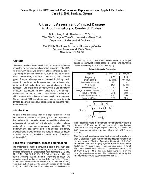
<strong>Ultrasonic</strong> <strong>Assessment</strong> <strong>of</strong> <strong>Impact</strong> <strong>Damage</strong><br />
<strong>in</strong> Alum<strong>in</strong>um/<strong>Acrylic</strong> Sandwich Plates<br />
B. M. Liaw, A. M. Pierides, and Y. X. Liu<br />
The City College <strong>of</strong> The City University <strong>of</strong> New York<br />
Department <strong>of</strong> Mechanical Eng<strong>in</strong>eer<strong>in</strong>g<br />
and<br />
The CUNY Graduate School and University Center<br />
Convent Avenue and 138th Street<br />
New York, NY 10031<br />
Abstract<br />
<strong>Ultrasonic</strong> studies were conducted to assess damages<br />
generated by <strong>in</strong>strumented drop-weight impact<strong>in</strong>g onto 6061-<br />
T6 alum<strong>in</strong>um/cast acrylic sandwich plates adhered by epoxy.<br />
Depend<strong>in</strong>g on several parameters, such as impact velocity,<br />
mass, temperature, sandwich construction, etc., various<br />
types <strong>of</strong> impact damage were observed, <strong>in</strong>clud<strong>in</strong>g plastic<br />
<strong>in</strong>dentation, radiat<strong>in</strong>g cracks emanat<strong>in</strong>g from the impact site,<br />
partial and full debond<strong>in</strong>g, and comb<strong>in</strong>ations <strong>of</strong> these<br />
damages. One major goal <strong>of</strong> this study is to use immersion<br />
ultrasound techniques <strong>in</strong> both pulse-echo and throughtransmission<br />
modes to detect these failure mechanisms,<br />
which were clearly visible s<strong>in</strong>ce cast acrylic is transparent.<br />
The developed NDT techniques can then be used to study<br />
damage behaviors <strong>in</strong> opaque composites, such as the fibermetal<br />
lam<strong>in</strong>ates.<br />
Introduction<br />
As part <strong>of</strong> the cont<strong>in</strong>u<strong>in</strong>g effort <strong>of</strong> a paper presented <strong>in</strong> the<br />
SEM Annual Conference last year [1], the ma<strong>in</strong> objectives <strong>of</strong><br />
this study are (i) to establish research capability <strong>in</strong> ultrasound<br />
techniques at the authors’ <strong>in</strong>stitute us<strong>in</strong>g sandwich plates<br />
made <strong>of</strong> two common commercial materials: 6061-T6<br />
alum<strong>in</strong>um and cast acrylic, and (ii) to develop prelim<strong>in</strong>ary<br />
understand<strong>in</strong>g <strong>of</strong> delam<strong>in</strong>ation and fracture caused by impact<br />
<strong>in</strong> other advanced sandwich panels (e.g., fiber-metal<br />
lam<strong>in</strong>ates [2-5]).<br />
Specimen Preparation, <strong>Impact</strong> & Ultrasound<br />
The materials for mak<strong>in</strong>g sandwich plates <strong>in</strong> this study are:<br />
(i) 6061-T6, a ductile alum<strong>in</strong>um-magnesium-silicon alloy with<br />
artificial temper<strong>in</strong>g for precipitation heat treatment (97.9 wt%<br />
Al, 1.0 Mg, 0.6 Si, 0.28 Mn, 0.2 Cr) and (ii) a brittle cast<br />
acrylic (PMMA). Typical material properties <strong>of</strong> these two<br />
materials useful for this study are listed <strong>in</strong> Table 1. Square<br />
panels with dimensions <strong>of</strong> 100 mm x 100 mm (or 4” x 4”)<br />
were then cut <strong>of</strong>f cast acrylic with a thickness <strong>of</strong> 6.3 mm (or<br />
0.25”) and 6061-T6 alum<strong>in</strong>um alloy with a thickness <strong>of</strong><br />
1.6 mm (or 1/16”). This study tested either pure acrylic<br />
panels or sandwich plates made <strong>of</strong> acrylic and alum<strong>in</strong>um<br />
panels adhered by a two-component epoxy.<br />
Table 1. Material Properties<br />
Property 6061-T6 acrylic<br />
Density, ρ<br />
g/cm 3 (ib/<strong>in</strong> 3 )<br />
2.70<br />
(0.0975)<br />
1.19<br />
(0.0430)<br />
Tensile Modulus, E<br />
GPa (Msi)<br />
69<br />
(10)<br />
3.0<br />
(0.44)<br />
Poisson Ratio, ν 0.33 0.36<br />
Longitud<strong>in</strong>al Wave Speed, c 1<br />
km/s (×10 3 <strong>in</strong>/s)<br />
6.15<br />
242<br />
2.06<br />
(81)<br />
Shear Wave Speed, c 2<br />
km/s (×10 3 <strong>in</strong>/s)<br />
3.10<br />
(122)<br />
0.96<br />
(38)<br />
⎧<br />
⎪c1<br />
=<br />
⎪<br />
Note: ⎨<br />
⎪<br />
c =<br />
⎩<br />
⎪ 2<br />
21+<br />
( 1−ν<br />
)<br />
( 1+ )( 1−2<br />
)<br />
E<br />
ρ ν ν<br />
E<br />
ν ρ<br />
( )<br />
The specimens were then clamped circumferentially along a<br />
diameter <strong>of</strong> 76 mm (or 3”) and impacted <strong>in</strong> an Instron-<br />
Dynatup 8250 drop-weight impact tester by a 16 mm- (or<br />
5/8”-) diameter spherical impactor with a weight <strong>of</strong> 6.1 kg (or<br />
13.4 lbs).<br />
The damaged specimens were first <strong>in</strong>spected visually and<br />
then C-scanned <strong>in</strong> both pulse-echo and through-transmission<br />
modes us<strong>in</strong>g a Physical Acoustics Corporation UltraPAC<br />
immersion ultrasonic imag<strong>in</strong>g system. Focused transducers<br />
(0.25”-dia., 1” focus length) <strong>of</strong> various frequencies (5 to 25<br />
MHz) were used for the pulse-echo operation whereas a pair<br />
<strong>of</strong> 0.25”-dia., 25 MHz flat transducer were used <strong>in</strong> the<br />
through-transmission mode. The schematic <strong>of</strong> a typical<br />
immersion ultrasound system is shown <strong>in</strong> Fig. 1.<br />
264
Results and Discussion<br />
The first case considered is the dropped-weight impact onto<br />
a cast acrylic plate by a 6.1 kg mass from a height <strong>of</strong> 51 mm<br />
(2”) and the test resulted <strong>in</strong> a star-shaped crack<strong>in</strong>g pattern.<br />
The ultrasound technique used here is schematically<br />
depicted <strong>in</strong> Fig. 2. As shown <strong>in</strong> Fig. 3 the optical image was<br />
reproduced fairly faithfully by the proposed ultrasound<br />
technique with the exception <strong>of</strong> a few horizontal white<br />
streaks which were mis-scanned po<strong>in</strong>ts due to the limitation<br />
<strong>of</strong> the ultrasound system. Regardless the transducer<br />
frequency (say, between 5 and 25 MHz) the ultrasound<br />
images detected the flaw pattern very accurately. In<br />
particular, the higher frequency transducer, which has a<br />
better resolution, produces more details <strong>of</strong> fracture,<br />
especially around the impact site.<br />
The ultrasound technique shown <strong>in</strong> Fig. 4 was then used to<br />
<strong>in</strong>spect the crack pattern and debond<strong>in</strong>g <strong>in</strong> a damaged<br />
alum<strong>in</strong>um/acrylic sandwich plate scanned from the acrylic<br />
side. The result<strong>in</strong>g C-scan images and the optical image are<br />
shown <strong>in</strong> Fig. 5, which aga<strong>in</strong> <strong>in</strong>dicates the high accuracy <strong>of</strong><br />
ultrasound <strong>in</strong>spection.<br />
The advantage <strong>of</strong> ultrasound technique is for flaw detection<br />
<strong>in</strong> an opaque material. We also used the technique shown <strong>in</strong><br />
Fig. 6 to scan the aforementioned damaged alum<strong>in</strong>um/<br />
acrylic sandwich plate from the alum<strong>in</strong>um side. The result<strong>in</strong>g<br />
optical and C-scan images are shown <strong>in</strong> Fig. 7. In this case<br />
only the <strong>in</strong>dentation and debond<strong>in</strong>g are detected by the<br />
ultrasound technique. Because <strong>of</strong> the presence <strong>of</strong><br />
debond<strong>in</strong>g, the back-echo signals from the cracked acrylic<br />
plate were “overshadowed” by the strong echoes from the<br />
debonded <strong>in</strong>terface. This is because ultrasound signals<br />
transmit poorly through the “air gap” with<strong>in</strong> the debonded<br />
area. The experimental evidence can be illustrated by a<br />
typical A-scan ultrasound signal shown <strong>in</strong> Fig. 8.<br />
To further verify the filter<strong>in</strong>g effect <strong>of</strong> debond<strong>in</strong>g on<br />
ultrasound signals, we adhered a pre-cracked acrylic plate to<br />
an alum<strong>in</strong>um panel; thus artificially remov<strong>in</strong>g the debond<strong>in</strong>g.<br />
The ultrasound technique shown <strong>in</strong> Fig. 9 was then used for<br />
C-scan from the alum<strong>in</strong>um side and the result<strong>in</strong>g image,<br />
along with their optical counterpart, are shown <strong>in</strong> Fig. 10. In<br />
this case, without the block<strong>in</strong>g effect from debond<strong>in</strong>g the<br />
crack<strong>in</strong>g pattern (as displayed <strong>in</strong> the optical image) was<br />
clearly detected by ultrasound. A typical A-scan signal<br />
show<strong>in</strong>g the identifiable back echo from cracked acrylic is<br />
illustrated <strong>in</strong> Fig. 11.<br />
F<strong>in</strong>ally as shown <strong>in</strong> Fig. 12, the impacted alum<strong>in</strong>um/acrylic<br />
plate studied <strong>in</strong> previously (see Fig. 5) was also scanned <strong>in</strong><br />
the through-transmission mode. Just like the case <strong>of</strong> pulseecho<br />
mode, the result<strong>in</strong>g ultrasound image, as shown <strong>in</strong> Fig.<br />
13, could only detect the debond while the crack<strong>in</strong>g was<br />
aga<strong>in</strong> shielded.<br />
Conclusions<br />
From this study one can conclude that<br />
• The ultrasound technique can detect crack and debond<br />
accurately <strong>in</strong> alum<strong>in</strong>um/acrylic sandwich plates so long<br />
as the back echo signals are not blocked by any<br />
discont<strong>in</strong>uity;<br />
• In general, all ultrasound transducers with commonly<br />
used frequencies, i.e., 5 to 25 MHz, can detect flaw<br />
accurately;<br />
• In particular, the transducers <strong>of</strong> higher frequency have<br />
better resolutions and can detect f<strong>in</strong>e details;<br />
• Both pulse-echo and through-transmission modes are<br />
workable for damage detection <strong>in</strong> relatively flat<br />
specimens.<br />
Acknowledgments<br />
This study was supported by NASA Faculty Award for<br />
Research (FAR) under Grant No. NAG3-2259 and by<br />
PSC-CUNY under Grants 61429-00 30 and 62466-00 31. Dr.<br />
Kenneth J. Bowles and Dr. John P. Gyekenyesi are the<br />
Technical Monitors <strong>of</strong> the NASA grant. Part <strong>of</strong> the equipment<br />
used <strong>in</strong> this <strong>in</strong>vestigation was acquired through Army<br />
Research Office Grant No. DAAD19-99-1-0366.<br />
References<br />
1. B.M. Liaw, G. Zeichner and Y.X. Liu, “<strong>Impact</strong><br />
delam<strong>in</strong>ation and fracture <strong>in</strong> alum<strong>in</strong>um/acrylic sandwich<br />
plates,” Proceed<strong>in</strong>gs <strong>of</strong> the SEM IX International<br />
Congress on Experimental Mechanics, Orlando, FL,<br />
June 5-8, 2000, pp. 515-518.<br />
2. A. Vlot, “<strong>Impact</strong> Properties <strong>of</strong> fiber metal lam<strong>in</strong>ates,”<br />
Composite Eng<strong>in</strong>eer<strong>in</strong>g, Vol. 3, No. 10, pp. 911-927,<br />
1993.<br />
3. C.T. Sun, A. Dicken, and H.F. Wu, “Characterization <strong>of</strong><br />
impact damage <strong>in</strong> ARALL lam<strong>in</strong>ates,” Composites<br />
Science and Technology, Vol. 49, pp. 139-144, 1993.<br />
4. H.F. Wu, “Temperature dependence <strong>of</strong> the tensile<br />
properties <strong>of</strong> ARALL-4 lam<strong>in</strong>ates,” J. <strong>of</strong> Materials<br />
Science, Vol. 25, pp. 1120-1127, 1990.<br />
5. B.M. Liaw, Y.X. Liu, and E.A. Villars, “<strong>Impact</strong> damage<br />
mechanisms <strong>in</strong> fiber-metal lam<strong>in</strong>ates,” this volume.<br />
Figure 1. Schematic <strong>of</strong> a typical immersion ultrasound<br />
system.<br />
265
Figure 2. Ultrasound technique for <strong>in</strong>spect<strong>in</strong>g a cracked<br />
acrylic plate.<br />
Figure 4. Ultrasound technique scann<strong>in</strong>g a damaged<br />
alum<strong>in</strong>um/acrylic sandwich plate from the acrylic<br />
side.<br />
Optical image<br />
C-scan (5 MHz)<br />
Optical image<br />
C-scan (5 MHz)<br />
C-scan (10 MHz)<br />
C-scan (15 MHz)<br />
C-scan (10 MHz)<br />
C-scan (15 MHz)<br />
C-scan (20 MHz)<br />
C-scan (25 MHz)<br />
Figure 3. Optical and ultrasound C-scan images <strong>of</strong> crack<strong>in</strong>g<br />
<strong>in</strong> an cast acrylic plate impacted by a dropped<br />
weight <strong>of</strong> 6.1 kg from 51 mm (2”) high.<br />
C-scan (20 MHz)<br />
C-scan (25 MHz)<br />
Figure 5. Optical and ultrasound C-scan images <strong>of</strong><br />
debond<strong>in</strong>g and crack<strong>in</strong>g scanned/photographed<br />
from the acrylic side <strong>of</strong> a n impacted<br />
alum<strong>in</strong>um/acrylic sandwich plate.<br />
266
Figure 6. Ultrasound technique scann<strong>in</strong>g a damaged<br />
alum<strong>in</strong>um/acrylic sandwich plate from the<br />
alum<strong>in</strong>um side.<br />
Figure 9. Ultrasound technique for <strong>in</strong>spect<strong>in</strong>g a<br />
pre-cracked acrylic plate shielded by an<br />
alum<strong>in</strong>um panel.<br />
Optical image<br />
C-scan (25 MHz)<br />
Figure 7. Optical and ultrasound C-scan images from the<br />
alum<strong>in</strong>um side <strong>of</strong> a damaged alum<strong>in</strong>um/acrylic<br />
sandwich plate.<br />
Optical image<br />
C-scan (25 MHz)<br />
Figure 10. Optical and ultrasound C-scan images <strong>of</strong> a<br />
pre-cracked acrylic plate shielded by an alum<strong>in</strong>um<br />
panel.<br />
Overdhadowed<br />
back echo<br />
Identifiable back echo<br />
Figure 8. An A-scan ultrasound signal show<strong>in</strong>g<br />
overshadowed back echoes.<br />
Figure 11. An A-scan ultrasound signal show<strong>in</strong>g<br />
identifiable back echoes.<br />
267
Figure 12. Through-transmission ultrasound.<br />
Figure 13. Through-transmission (0.25”-dia., 25 MHz flat<br />
transducers) ultrasound C-scan image <strong>of</strong> a<br />
damaged alum<strong>in</strong>um/acrylic sandwich plate<br />
scanned from the alum<strong>in</strong>um side.<br />
268