HYDRAULICS AND DESIGN OF FUSEGATES Hasan T ... - Hydroplus
HYDRAULICS AND DESIGN OF FUSEGATES Hasan T ... - Hydroplus
HYDRAULICS AND DESIGN OF FUSEGATES Hasan T ... - Hydroplus

Create successful ePaper yourself
Turn your PDF publications into a flip-book with our unique Google optimized e-Paper software.
<strong>HYDRAULICS</strong> <strong>AND</strong> <strong>DESIGN</strong> <strong>OF</strong> <strong>FUSEGATES</strong><br />
<strong>Hasan</strong> T. Kocahan, Business Development Manager, <strong>Hydroplus</strong>, Inc.<br />
PO Box 1731<br />
Falls Church, VA 22041, USA<br />
Phone : 703-575-9075, Fax: 703-575-9193<br />
INTRODUCTION:<br />
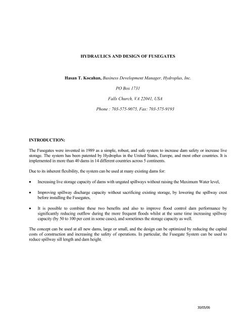
The Fusegates were invented in 1989 as a simple, robust, and safe system to increase dam safety or increase live<br />
storage. The system has been patented by <strong>Hydroplus</strong> in the United States, Europe, and most other countries. It is<br />
implemented in more than 40 dams in 14 different countries across 5 continents.<br />
Due to its inherent flexibility, the system can be used at many existing dams for:<br />
• Increasing live storage capacity of dams with ungated spillways without raising the Maximum Water level,<br />
• Improving spillway discharge capacity without sacrificing existing storage, by lowering the spillway crest<br />
before installing the Fusegates,<br />
• It is possible to combine these two benefits and also to improve flood control dam performance by<br />
significantly reducing outflow during the more frequent floods whilst at the same time increasing spillway<br />
capacity (by 50 to 100 per cent in some cases), and sometimes the storage capacity as well.<br />
The concept can be used at all new dams, large or small, and the design can be optimized by reducing the capital<br />
costs of construction and increasing the safety of operations. In particular, the Fusegate System can be used to<br />
reduce spillway sill length and dam height.<br />
30/05/06
1. PRINCIPLE <strong>OF</strong> THE SYSTEM<br />
1.1 DESCRIPTION<br />
The Fusegate System is based on the following concept:<br />
• Fusegates are free-standing units installed side-by-side on a spillway sill to form a watertight barrier.<br />
• They bear against small abutment blocks set in the sill to prevent them from sliding before they are<br />
required to rotate (under extreme flood conditions).<br />
• There is a chamber in the base of each Fusegate, with drain holes to discharge incidental inflow (due<br />
to leaking seals for example).<br />
• An inlet well on the upstream side of the Fusegate crest discharges water into the chamber when the<br />
headwater reaches a predetermined level (see figure 3).<br />
Bucket<br />
Inlet well<br />
Overspilling crest<br />
Side seal<br />
Downstream<br />
abutment block<br />
Side abutment block<br />
Downstream<br />
bucket side<br />
Concrete sill<br />
Upstream seal strip<br />
Figure 1: Typical 3D view of a Fusegate<br />
1.2 NORMAL OPERATING CONDITION<br />
In normal operating conditions, the Fusegates act as a watertight barrier. Medium to moderate floods are simply<br />
discharged above the Fusegate crest as they would do over a free weir (see figure 2).<br />
30/05/06
Water inlet<br />
Ballast<br />
Drain hole<br />
Abutment<br />
block<br />
Underface<br />
1.3 EXCEPTIONAL FLOOD EVENT<br />
Figure 2: water spills over the Fusegate<br />
If the reservoir level exceeds a predetermined value, water will flow into the inlet well and cause an uplift<br />
pressure to develop in the chamber (see figure 3).<br />
Figure 3: well being fed<br />
The uplift pressure, combined with the hydrostatic pressure (acting from left to right on the adjacent<br />
diagram) is sufficient to overcome the restraining forces and the imbalance causes rotation of the unit off<br />
the spillway. The Fusegate is then washed away clear of the spillway by the flood (see figure 4).<br />
Figure 4: Fusegate tipping<br />
30/05/06
Each Fusegate has a different overturning level, precisely determined by the height of the water inlet and its own<br />
unique stability.<br />
If the water level continues to rise after the first breach more Fusegates can rotate, all according to predetermined<br />
upstream water levels, until eventually there are no more units remaining and the spillway is<br />
free to pass the original maximum design flood.<br />
The economic impact of the Fusegates rotation is to be regarded considering the low probability of the<br />
corresponding flood event, which can be adjusted accordingly (generally between 1 in 200 year and 1 in<br />
1000 year flood). For instance, the first Fusegate to rotate at Kaweah Lake, California tips for floods in<br />
excess of the 1 in 1000 year flood. Until rotation of the first Fusegate, the user has the benefit of the<br />
additional storage and the system operates as any other ungated dam.<br />
Fusegate could be considered as the mechanical equivalent of a Fuseplug. However, when the Fuseplug<br />
begins to operate, the entire plug fails. In contrast, with Fusegates, only the number of units required to<br />
pass a flood are operational. In addition, reservoir elevations at which each Fusegate tilts can be more<br />
precisely controlled.<br />
2. <strong>DESIGN</strong> <strong>OF</strong> A FUSEGATE<br />
2.1. LABYRINTH <strong>FUSEGATES</strong><br />
When installed, labyrinth crested Fusegates reproduce the shape of a labyrinth weir in which each Fusegate<br />
represents one cycle of the labyrinth (see figure 1).<br />
The height of a labyrinth crested Fusegates can be customized to meet any project requirements. Review of the<br />
projects implemented so far shows that the Fusegate height ranges between 4’ and 22’.<br />
Labyrinth crested Fusegates are available in three standard configurations which are designated by the width of<br />
the Fusegate to its height as being wide (W) or narrow (N) and by the tilting range as being low head (LH) or<br />
high head (HH). The features of each of the configuration are given on figure 5.<br />
Tilting range<br />
Ratio of width to height<br />
(in % of the Fusegate height)<br />
Narrow Low Head (NLH) Between 30% H and 70% H 1,0 (+/-5%)<br />
Large Low Head (LLH) Between 30% H and 70% H 1,5 (+/-5%)<br />
Large High head (LHH) Between 70% H and 140% H 1,8 (+/-5%)<br />
Figure 5: main features of labyrinth crested Fusegates<br />
Detailed hydraulic investigation of the Fusegate discharge characteristics were conducted at the Tennessee<br />
Valley Authority in Norris, Tennessee and in other reputable laboratories around the world. It was found that the<br />
discharge characteristics can be closely analyzed by the following formula :<br />
2<br />
3<br />
If h>h c H Q = A H h + BH<br />
where Q is the discharge per linear feet, H the Fusegate height, A and B discharge coefficients (dependant on the<br />
Fusegate geometry) and h the difference in the reservoir and the crest elevation. The discharge parameters are<br />
given in figure 6.<br />
It will be noted that the above formula differs from the relation generally applied to free weir (where the<br />
discharge depends on h at the power 3/2). This is explained by the submergence of the labyrinth, which reduces<br />
the hydraulic efficiency as the flow depth over the Fusegate increases.<br />
30/05/06
A B h c<br />
Narrow Low Head (NLH) 4.836 -0.145 0.262<br />
Large Low Head (LLH) 4.523 -0.093 0.591<br />
Large High head (LHH) 5.606 -0.281 0.427<br />
Figure 6: discharge parameters<br />
The labyrinth shape of the Fusegates enables the system to discharge 1.5 to 2.5 times more water than a<br />
conventional ogee crest.<br />
Fusegates are designed to operate with an aerated nappe. The tests at TVA showed that the discharge coefficient<br />
was constant up to the point where tailwater was equal to the crest elevation. The effects of submergence and<br />
nappe interaction on the discharge coefficients observed on fixed labyrinth weirs are not significant with<br />
Fusegates.<br />
2.2. STRAIGHT <strong>FUSEGATES</strong><br />
The functioning principle of straight crested Fusegates is similar. Straight and labyrinth types of Fusegates differ<br />
only by the shape of the overspilling crest.<br />
Figure 7: straight crested Fusegates<br />
Straight crested Fusegates are generally considered when the conditions of applications do not allow for using<br />
labyrinth crested Fusegates or when a high discharge efficiency is not required. The latter case is typically when<br />
Fusegates are installed on an emergency or secondary spillway.<br />
30% 70% 140%<br />
h/H<br />
Straight<br />
Fusegates<br />
Labyrinth<br />
Fusegates<br />
Low Head<br />
Labyrinth<br />
Fusegates<br />
High Head<br />
Straight Fusegates<br />
Figure 8: Typical field of application of straight crested Fusegates versus labyrinth crested Fusegates<br />
30/05/06
Straight crested Fusegates can be engineered to withstand an overspilling in excess of 350% of their crest height.<br />
Straight crested Fusegates can be fully customized, since no particular ratio of width to height is required. The<br />
only recommendation is to keep the Fusegate width larger than its height.<br />
The discharge characteristics are expressed using the discharge coefficient Cd for weirs defined by Rouse (1960)<br />
as:<br />
2<br />
3<br />
2<br />
Q = Cd<br />
2gh<br />
3<br />
where Q is the discharge per linear feet, g the acceleration of gravity and h the difference in the reservoir and the<br />
crest elevation.<br />
Model tests undertaken show that the value of C d ranges between 0.61 and 0.64 depending on the Fusegate<br />
shape and spillway configuration.<br />
3. STABILITY ANALYSIS<br />
3.1. LOADS<br />
Loads causing overturning moment<br />
Fs upstream hydrostatic force<br />
Fuc uplift force within the chamber<br />
Fud uplift forces under the beams<br />
Loads causing resisting moment<br />
Fg dead load of the Fusegate<br />
Fw water load above the Fusegate<br />
Fd downstream hydrostatic force<br />
3.2. UPLIFT IN CHAMBER <strong>AND</strong> ON UNDERSIDE <strong>OF</strong> BASE<br />
Theoretical analysis and model tests have been conducted to determine the uplift distribution in the<br />
chamber under normal conditions and in all conceivable critical situations.<br />
Under normal conditions, the upstream seal prevents water from entering the chamber. When the Fusegate<br />
is spilling, leakage between the underside of the base and the sill will be discharged through the drain<br />
holes at the downstream edge.<br />
These drain holes are large enough so that normal leakage into the chamber from downstream will be<br />
discharged with a near-zero depth of water in the chamber. The pressure in the chamber in such<br />
circumstances is called the “natural uplift pressure”.<br />
Model tests considering the scenario of a Fusegate with its upstream edge slightly lifted off the sill were<br />
performed. They allowed for determining the magnitude of the maximum uplift pressure which can be<br />
30/05/06
generated in the chamber. The pressure in the chamber in such theoretical circumstance is called the “liftoff<br />
uplift pressure”.<br />
The Fusegates are engineered to tip-off when the uplift reaches a predetermined value ranging between the<br />
natural and lift-off uplift pressures.<br />
3.3. TYPICAL STABILITY CURVE<br />
The stability curve (see figure 9) shows the stabilizing moments and overturning moments as a function of<br />
the reservoir level (measured with reference to the Fusegate base). The Fusegate overturns when these two<br />
moments are equal.<br />
700<br />
600<br />
Stabilising Moment<br />
Overspilling<br />
starts<br />
Normal<br />
tipping level<br />
Overturning Moment<br />
500<br />
Moment<br />
400<br />
300<br />
Water enters<br />
into well<br />
200<br />
100<br />
0<br />
0,0 1,0 2,0 3,0 4,0 5,0 6,0 7,0 8,0<br />
U/S water level above fusegates base<br />
Figure 9: Stability curves, normal conditions.<br />
The stability margin of a Fusegate is defined as the difference between the stability and the overturning<br />
moment for any assumed upstream water level. It will noted from figure 9 that high stability margins are<br />
achieved until the well is fed. It reduces the possible effect of abnormal load cases such as impacts of<br />
floating debris as well as for withstanding quite large earthquakes as discussed in paragraph 4.<br />
3.4. SAFETY LEVELS<br />
The stability curve of a Fusegate can also be computed under two theoretical scenarios, namely with liftoff<br />
uplift pressure in the chamber and with the wells being completely inefficient.<br />
30/05/06
700<br />
600<br />
Stabilising Moment<br />
Overspilling<br />
starts<br />
Normal<br />
tipping level<br />
500<br />
Overturning Moment with natural uplift pressure<br />
Overturning Moment with lift-off uplift pressure<br />
Moment<br />
400<br />
300<br />
200<br />
100<br />
Minimum<br />
tipping<br />
level<br />
Ultimate<br />
stability<br />
level<br />
0<br />
0,0 1,0 2,0 3,0 4,0 5,0 6,0 7,0 8,0 9,0 10,0<br />
U/S water level above fusegates base<br />
Figure 10: Stability curve with uplift pressure limit value<br />
The case with lift-off uplift pressure in the chamber determines the minimum tipping level below which<br />
the Fusegate will return to its normal position even if the chamber is full (due to the impact by a very large<br />
floating debris , or water entered intentionally through the well)<br />
The case with the well being completely inefficient (as a result of sabotage for instance) is called the<br />
ultimate stability level at which the Fusegate overturns even without water entering the well. In this case,<br />
the Fusegate rotate under the effect of the upstream pressure only.<br />
4. OPERATIONAL RELIABILITY<br />
4.1. SAFETY <strong>OF</strong> DOWNSTREAM POPULATION<br />
The minimum tipping level defines the head below which the Fusegate can not rotate regardless of the<br />
scenario envisaged.<br />
The minimum tipping level can be fixed at a given elevation by adjusting the amount of ballast (and thus<br />
the uplift pressure triggering the tip-off). The dam owner can specify his minimum tipping level and the<br />
magnitude of the corresponding flood.<br />
This engineered safeguard is of vital importance for the people living downstream since it removes the<br />
risk of a sudden artificial flood in the absence of a natural river flood.<br />
4.2. DAM SAFETY<br />
The ultimate stability level is the reservoir level for which the Fusegate overturns even in the unlikely case<br />
of the well being completely blocked.<br />
Since the individual Fusegates are independent from each another, the probability of this situation<br />
occurring on the whole set is practically nil.<br />
30/05/06
Depending on the dam operator goals, the design of the Fusegates will be such that floods of very low<br />
probably of occurrence can be discharged without endangering the dam, even with many of the wells<br />
being blocked.<br />
4.3. CRITICAL SITUATIONS<br />
Besides the blocked well situation, the safety analyses conducted also takes into account the cases of the<br />
upstream seal being completely destroyed and the drain holes being blocked. These are entirely theoretical<br />
situations, which could occur only through willful damage or complete dereliction of the dam inspection.<br />
Destruction of the upstream seal may lead to an increase in the chamber pressure because of leakage from the<br />
reservoir, although again, this cannot cause the Fusegate to tip-off before water is admitted through the well.<br />
Drain holes blockage causes the pressure in the chamber to approximate the back-pressure downstream.<br />
However, the Fusegate will not rotate before the well is fed.<br />
4.4. SPECIFIC DAM CONDITIONS<br />
The design of a Fusegate System for any specific project should also include the effect of waves, floating debris<br />
and impacts of earthquake as well as of ice conditions. Mathematical models were developed to properly assess<br />
those effects depending on the particular project constraints.<br />
• Waves, floating debris and impacts<br />
The effect of waves and impacts have been the subject of specific research in reputable hydraulic laboratories<br />
(such as Utah State University, Tennessee Valley Authority), which have demonstrated their minimal incidence<br />
on the system. Floating debris are simply discharged over the Fusegates’ crest when sufficient spillage occurs,<br />
and do not have any significant impact on the Fusegate stability.<br />
Example of impact of large floating debris (Tennessee Valley Authority)<br />
• Earthquake<br />
Seismic effects can be examined in each individual project using a pseudo-static approach or a finite element<br />
analysis, if required. However, the stability of the Fusegates is usually sufficient to prevent problems induced by<br />
earthquakes.<br />
The behavior of the Fusegates during a major seism has been observed in Gujarat State in India that was hit early<br />
2001 by a 7,6 magnitude (on the Richter scale) seism. None of the Fusegates installed on the four dams located<br />
within a 50 miles radius from the epicenter have been affected.<br />
• Ice-affected environments<br />
30/05/06
The effect of ice is examined with reference to tests undertaken in the hydraulic laboratories of the National<br />
Research Council (NRC) in Newfoundland, Canada and of the Institute of Energy Structures in Moscow,<br />
Russia. Generally speaking, thermal expansion of ice and ice run off generally have very little influence on the<br />
Fusegates stability.<br />
The behavior of the Fusegates in ice-affected environments has been observed on Khorobrovskaya scheme<br />
(located in Russia). The 4 off 6.6-foot high Fusegate units have successfully withstood the pressure of the 2-foot<br />
thick ice coat and to the subsequent ice run-off.<br />
Model tests at the NRC<br />
Khorobrovskaïa in winter<br />
4.5. INHERENT SAFETY FEATURES<br />
The Fusegate System has valuable safety features inherent to the concept and not shared by any other<br />
spillway control systems<br />
• Fusegates are entirely self-operating and do not require any source of power to operate.<br />
• Only minimal maintenance is required compared to other mechanical gates.<br />
• Fusegates overturn automatically, responding to those physical forces acting upon them.<br />
The Fusegate massive structure offers little vulnerability to vandalism and, considering their high stability<br />
margin, to terrorist threat.<br />
5. CONCLUSION<br />
Fusegates are a simple, safe and robust method in increasing live storage or spillway capacity. The goal of the<br />
fusegate design rules is to maximize safety for the dam and the downstream population. Abnormal operating<br />
conditions may affect the precision of the system but not the reliability expected by the dam Owner.<br />
Fusegates cannot overturn when headwater is below the minimum tipping level. There is no risk of creating an<br />
artificial flood in the absence of a river flood upstream, which is a primordial safety consideration for the<br />
inhabitants living downstream of a dam. Even if the water is prevented from flowing into the inlet well,<br />
fusegates will always overturn when headwater reaches the ultimate stability level. This level is below the level<br />
which would be dangerous for the dam.<br />
These safety features are very significant advantages over all other existing spillway control systems.<br />
30/05/06
REFERENCES<br />
Lemperiere F., and Bessiere C., (1992). “HYDROPLUS submersible Fusegates for surface spillways.”<br />
Modification of dams to accommodate major floods, USCOLD, Fort Worth, Dallas, Texas.<br />
Hay N., and Taylor G., (1970). “ Performance and design of labyrinth weirs.” Journal of Hydraulic Div., 96(11),<br />
2237-2357.<br />
Falvey H, and Treille P., (1995). “Hydraulics and design of Fusegates”, Journal of Hydraulic Engineering, July<br />
1995, 512-518.<br />
Taylor G.M., Mahooty D., Rayssiguier J., “Historic dam, modern upgrade”, USSD conference, Denver July<br />
2001<br />
Aït Alla A. “The Role of Fusegates in Dam Safety”. Hydropower & Dams. Volume Three, Issue Six, 1996.<br />
Jones S.J., Spencer D., Rodionov V.B. and Lounatsi M.E., Aït Alla A. “The Reliability of Fusible Gates in Ice-<br />
Affected Environments”, Hydropower & Dams. Volume Three, Issue Three, 1996.<br />
30/05/06