SWM6000 / SWM7000 (.pdf) (English) - Sabine, Inc.
SWM6000 / SWM7000 (.pdf) (English) - Sabine, Inc.
SWM6000 / SWM7000 (.pdf) (English) - Sabine, Inc.

You also want an ePaper? Increase the reach of your titles
YUMPU automatically turns print PDFs into web optimized ePapers that Google loves.
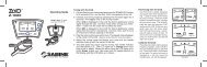
Operating Guide<br />
<strong>SWM6000</strong> 915 MHz Systems<br />
<strong>SWM7000</strong> 2.4 GHz Systems<br />
WIRELESS MICROPHONES<br />
WIRELESS SYSTEMS<br />
the sound of innovation
Declaration of Conformity<br />
EC - DECLARATION OF CONFORMITY<br />
CE Ma r k i n g<br />
We, the Manufacturer<br />
SABINE, INC.<br />
13301 NW US HIGHWAY 441<br />
ALACHUA, FLORIDA USA<br />
declare that the products<br />
Receiver: SABINE MODEL <strong>SWM7000</strong><br />
Is in conformity with<br />
Council Directive: 73/23/EEC and 89/336/EEC (EMC Directives)<br />
Standards to which conformity is declared:<br />
EN 60065: 2001<br />
EN 55022: 1998 Class B<br />
EN 50082-1: 1998<br />
Transmitters: SABINE MODEL SW70-H and SW75-T<br />
Is in conformity with<br />
Council Directive: 73/23/EEC and 89/336/EEC (EMC Directives)<br />
Standards to which conformity is declared:<br />
EN 300422-1, 2<br />
EN 300440-1<br />
EN 301489-9<br />
Manufacturer Signature: __________________________<br />
Date: 28 __________ April, 2003<br />
Name: __________________________<br />
Doran Oster, President<br />
© 2011 <strong>Sabine</strong>, <strong>Inc</strong>.<br />
3 <strong>Sabine</strong> Smart Spectrum ® Wireless<br />
LIT-SWM6-7000-OG-EN-110203.indd
© 2011 <strong>Sabine</strong>, <strong>Inc</strong>.<br />
Table of Contents<br />
1. Introduction 5<br />
1.1. Section Contents 5<br />
2. Product Views 6<br />
2.1. Receivers 6<br />
2.1.1. Front panel views 6<br />
2.1.2. Back panel Views 6<br />
2.2. Transmitters 7<br />
2.2.1. Handheld 7<br />
2.2.2. Beltpack 7<br />
2.3. Components 7<br />
3. Quick Setups 8<br />
3.1. Receiver & Transmitter Quick Setup 8<br />
3.2. FBX Quick Setup 8<br />
3.3. Tips for Good RF Performance 12<br />
3.4. Common Sources of RF Interference 12<br />
4. Transmitter Operation 14<br />
4.1. First step 14<br />
4.2. Displays and Settings 14<br />
4.2.1. LCD Display 14<br />
4.2.2. Accessing Transmitter Controls 15<br />
4.2.3. Adjusting Transmitter Settings 16<br />
4.2.4. Transmitter Battery Management 17<br />
5. Receiver Operation 20<br />
5.1. LCD Display. 20<br />
5.2. Parameter Control & LCD Display 22<br />
5.2.1. One set of Controls for 1 or 2 Channels 22<br />
5.2.2. Channel Select / Contrast Button. 22<br />
5.2.3. Special LCD Display Messages. 23<br />
5.3. RF Channel Select 23<br />
5.4. Output Level 23<br />
5.5. Channel Mixing 23<br />
5.5.1. How to toggle channel mixing mode 23<br />
5.5.2. Controlling the reciever in channel mixing mode 24<br />
5.6. Guitar Cord Simulating 24<br />
5.7. Receiver Antenna Placement 24<br />
5.7.1. Multi-path Interference 24<br />
5.7.2. Receiver & Antenna Placement Tips 24<br />
6. Mic SuperModeling 26<br />
6.1. Introduction 26<br />
6.2. Emulation Choices 26<br />
6.3. Mic Modeling Front Panel Control 26<br />
6.4. Future Microphone Modeling Choices 27<br />
6.4.1. Mic Model Upgrade Instructions 27<br />
7. FBX Feedback Exterminator® 28<br />
7.1. FBX Introduction 28<br />
7.1.1. FBX Fixed Filters 28<br />
7.1.2. FBX Dynamic Filters 28<br />
7.1.3. Balancing Fixed & Dynamic Filters 28<br />
7.1.4. FBX Filter Width 28<br />
7.2. FBX Set Up 28<br />
7.2. FBX Bypass Button 29<br />
8. Compressor/Limiter Operation 30<br />
8.1. Basics of Compression 30<br />
8.2. Using the Compressor 30<br />
8.3. Suggested Compression Settings 31<br />
8.3.1. Vocal Settings 31<br />
8.3.2. Guitar Settings 31<br />
This operating guide written for receivers using <strong>Sabine</strong> SWM Remote Control<br />
Software version 2.0 and above.<br />
<strong>Sabine</strong> Smart Spectrum ® Wireless<br />
4<br />
9. De-esser 33<br />
9.1. De-mystifying De-essers 33<br />
9.2. The <strong>Sabine</strong> De-esser 33<br />
9.3. Using the De-esser 33<br />
10. Program save & recall 34<br />
10.1. Saving a Preset 34<br />
10.2. Loading a Preset 34<br />
10.3. Naming a Preset 34<br />
10.4. Power Off Memory 34<br />
11. Multiple Systems Operation 35<br />
11.1. Overview 35<br />
11.1.1. Multiple System Interference 35<br />
11.1.2. Setup Complexity 35<br />
11.2. Antenna Distribution Amplifier 36<br />
11.3. Antenna Distribution Amplifier Connection 36<br />
12. Extension Antennas 38<br />
12.1. Overview 38<br />
12.2. Antenna Cabling & Cable Loss 38<br />
13. REMOTE CONTROL OPERATION 40<br />
13.1. Overview 40<br />
13.1.1. Single vs. Multiple Receiver Control 40<br />
13.1.2 Features & Controls Added Software 40<br />
13.1.3. Software Multiple Unit Control 42<br />
13.2. Software Installation 42<br />
13.2.1. Requirements & Recommendations 42<br />
13.2.2. Connections 42<br />
13.2.3. Installing the Software 43<br />
13.3. Launching the software 43<br />
13.3.1. Off-Line Edit/Demo 43<br />
13.3.2. Connecting Receivers. 43<br />
13.4. Remote Control Operation 44<br />
13.4.1. Two Views, Two Sets of Controls 44<br />
13.4.2. Menus, Icons & Hot Keys 44<br />
14. Tips & Troubleshooting 48<br />
14.1. Tips for Maximum Performance 48<br />
14.2. Troubleshooting 48<br />
14.3. Common Sources of RF Interference 49<br />
14.3.1 RF Sources 49<br />
15. FBX Theory & Practice 51<br />
15.1. Introduction to FBX® 51<br />
15.2. The Advantages of FBX Filters 51<br />
15.3. Parametric Filters and FBX 52<br />
15.3.1. The FBX & True Mobility® Advantage 53<br />
14.3.2. FBX Fixed & Dynamic Filters 53<br />
14.3.3. FBX Filter Width 54<br />
14.3.4. Who Benefits from FBX 54<br />
15. Appendices 55<br />
Appendix A: Beltpack Connector Wiring Diagrams 55<br />
Appendix B: Antenna System Diagrams 55<br />
Appendix C: Specifications 56<br />
Appendix D: Dip Switch Settings 58<br />
Appendix E: Frequency Chart 59<br />
Appendix F: Battery Endurance Tests (Typical) 60<br />
Appendix G: Changing Audix Mic Capsules (SW70-H) 60<br />
16. CAUTIONS & WARRANTY 61<br />
INDEX 63
Introduction<br />
1. Introduction<br />
Congratulations on purchasing your <strong>Sabine</strong> Smart Spectrum True Mobility Wireless System. True Mobility Wireless Systems<br />
give you all the built-in processing you need on every microphone, and offer unique and powerful features unavailable<br />
with any other wireless microphone.<br />
1.1. Section Contents<br />
Section 2 Product Views — illustrates system components (front & back panel views, transmitters, accessory lists and<br />
part numbers).<br />
Section 3<br />
Section 4<br />
Section 5<br />
Section 6<br />
Section 7<br />
Section 8<br />
Section 9<br />
Section 10<br />
Section 11<br />
Section 12<br />
Section 13<br />
Section 14<br />
Section 15<br />
Section 16<br />
Index<br />
Quick Setup — gives the Quick Setup procedures for Receiver & Transmitter Operation and using the FBX<br />
Feedback Exterminator ® . Note that there is also a quick-start label on top of your True Mobility receiver for<br />
the <strong>Sabine</strong> FBX Feedback Exterminator ® , Compressor/Limiter and De-Esser functions.<br />
Transmitter Operation — details transmitter setup and operation.<br />
Receiver Operation — details receiver installation and setup.<br />
Mic SuperModeling — explains the use of the <strong>Sabine</strong> Mic SuperModeling and lists the microphones<br />
modeled.<br />
FBX Feedback Exterminator ® — explains how to set up your FBX filters.<br />
Compressor/Limiter — explains the use of the Compressor.<br />
De-Esser — details operation of the adaptive De-Esser.<br />
Program Save & Recall — explains how to save and recall individual program settings.<br />
Multiple Systems — how multiple systems interface, computer control of multiple systems, suggestions for<br />
maximizing the number of collocated systems.<br />
Extension Antennas — how to get maximum performance using a <strong>Sabine</strong> Extension Antennas (Antenna<br />
Distribution Amplifier also available for multi-receiver installations).<br />
<strong>Sabine</strong> Remote Control Software — how to control up to 70 channels from one PC.<br />
Tips & Troubleshooting — gives tips on how to get the best performance from your <strong>Sabine</strong> Wireless, and<br />
describes some possible operating problems and their solutions.<br />
Appendices — wiring diagrams, frequency charts, specifications, typical system diagrams and dip switch<br />
settings for <strong>Sabine</strong> Wireless systems.<br />
Cautions & Warranties — states caution and warranty information for your True Mobility Wireless system.<br />
Important note about using this Operating Guide<br />
This guide covers the operation of both the <strong>SWM6000</strong> and <strong>SWM7000</strong> Wireless Systems.<br />
The basic operating procedures for these two series are the same. The crucial differences<br />
are the frequency bands each of these series uses, and the number of available channels.<br />
<strong>SWM6000</strong>: Offers 34 channels, and uses the 915 MHz band. All transmitters and receivers<br />
include the number “6” or the designation “M9” in the part number to denote this series.<br />
<strong>SWM7000</strong>: Offers 70 channels, and uses the 2.4 GHz band. All transmitters and receivers<br />
include the number “7” or the designation “M1” in the part number to denote this series.<br />
These products may be used together in the same location, but remember that transmitters<br />
and receivers must always work together. For example, in order for an <strong>SWM6000</strong> Series<br />
system to work, the transmitters and receivers must both be from that series.<br />
© 2011 <strong>Sabine</strong>, <strong>Inc</strong>.<br />
Other components in your system can be mixed between these two series. These include<br />
lavalier and headworn mics, mic clips and chargers, cables and adaptors, and anything that is<br />
not involved in the transmission or reception of the wireless signal.<br />
5 <strong>Sabine</strong> Smart Spectrum ® Wireless<br />
LIT-SWM6-7000-OG-EN-110203.indd
Product Views<br />
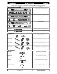
2. Product Views<br />
2.1. Receivers<br />
2.1.1. Front panel views<br />
Antenna 1<br />
Front Mount<br />
Ch. A<br />
Display<br />
Ch. A<br />
Channel<br />
Select,<br />
Contrast<br />
FBX<br />
Mic Deesser<br />
Model<br />
Compressor<br />
Limiter<br />
RF Ch.<br />
Select<br />
Output<br />
Level<br />
Program<br />
Ch. B<br />
Channel<br />
Select,<br />
Contrast<br />
Ch. B<br />
Display<br />
Power Antenna 2<br />
Front Mount<br />
Fig. 2a - SW72-NDR & SW72-R (SW62-NDR & SW62-R) Two-channel Receivers<br />
Fig. 2b - SW71-R (SW62-R) One-channel Receiver<br />
2.1.2. Back panel Views<br />
Antenna 2 AES3 Sync<br />
Digital Output Input<br />
AC Power<br />
& Fuses<br />
RS485 Network<br />
RS232<br />
Serial<br />
USB Port,<br />
Dip Switches<br />
Mic/Line Balanced<br />
Output B<br />
Mic/Line Balanced<br />
Output A<br />
Antenna 1<br />
Fig. 2c - SW72-NDR (SW62-NDR) Two-channel Receiver w/Network & Digital Interface<br />
Fig. 2d - SW72-R (SW62-R) Two-channel Receiver<br />
Fig. 2e - SW71-R (SW61-R) One-channel Receiver<br />
See Page 55 for the chart<br />
of DIP Switch Settings<br />
© 2011 <strong>Sabine</strong>, <strong>Inc</strong>.<br />
<strong>Sabine</strong> Smart Spectrum ® Wireless<br />
6
Product Views<br />
2.2. Product Transmitters Views<br />
2.2.1. Handheld<br />
1<br />
3<br />
2<br />
Transmitter Controls<br />
1 Select Button<br />
2 Up Button<br />
3 Down Button<br />
Switch<br />
LCD<br />
Battery<br />
SWC-POWR<br />
plug-in charger jack<br />
Shown with cable<br />
attached. Requires<br />
assembly.<br />
Fig. 2h - SWC70CL - SW70-H13 (SW60-H13), SW70-H15 (SW60-H15) & SW70-H19 (SW60-H19) Mic Clip with Built-in Charger<br />
2.2.2. Beltpack<br />
o n o n o n<br />
o f f m u t e o n<br />
1 2<br />
Antenna<br />
s e l e c t<br />
2.4 GHz SMART SPECTRUM<br />
u p<br />
d o w n<br />
3<br />
Switch<br />
TA4<br />
Mini-XLR<br />
Connector<br />
Top view<br />
SWC-POWR<br />
plug-in charger<br />
jack<br />
Belt clip<br />
Battery<br />
© 2011 <strong>Sabine</strong>, <strong>Inc</strong>.<br />
Fig. 2i - SW65 and 75-T Beltpack Transmitter<br />
2.3. Components<br />
(for a complete list see the <strong>Sabine</strong> Catalog)<br />
Receivers<br />
SW62 and 72-NDR: 2-Ch. Receiver w/Network & Digital Interface<br />
SW62 and 72-R: 2-Ch. Receiver<br />
SW61 and 71-R: 1-Ch. Receiver<br />
Microphones<br />
SWT31L-TA4: Cardioid Lavalier Mic<br />
SWT56W-TA4: Headworn Mic<br />
SVT70BW-TA4: Voice Technologies Omni Headworn Mic (Black)<br />
SVT70LW-TA4: Voice Technologies Omni Headworn Mic (Tan)<br />
SVT80BW-TA4: Voice Technologies Cardioid Headworn Mic (Black)<br />
SWTVT50-TA4: Voice Technologies Miniature Omni Lavalier<br />
SVT40L-TA4: Voice Technologies Sub-Mini Omni Lavalier<br />
SWT70G-TA4: Instrument Input w/cable<br />
Transmitters<br />
SW65 and 75-T: Beltpack Transmitter<br />
SW60 and 70-H13: Handheld Mic w/Dynamic Element (Audix OM3)<br />
SW60 and 70-H15: Handheld Mic w/Dynamic Element (Audix OM5)<br />
SW60 and 70-H19: Handheld Mic w/Condenser Element (VT)<br />
!<br />
Antennas<br />
SWA700: TNC Front to Rear Converter Kit (Set of 2)<br />
SWA6SS: Antenna Distribution Amp for 6 systems<br />
SWASS-EXT: Extension Antenna Kit (Set of 2)<br />
SWAANT: Dipole Antennas (2)<br />
SWATNC-N: RF Adaptor cable, Set of 4, TNC to NB<br />
SWATNC-MCA: TN C Male Crimp Connector 2.4 GHz<br />
SWACA15(or 30)-TNC: RF Cables, RG58, TNC, One Pair<br />
Batteries<br />
SWBAA2: Rechargeable NiMH AA set for SW75-T & H1<br />
Mic & Transmitter Accessories<br />
SWCRJ45: RS485 Serial Cable for ND Receivers<br />
SWC70CL-1: SW60/70-H Mic Holder w/Built-in Charger<br />
SWC70CL-12: Stage clip for SW70-H<br />
SWCPOWR-EXT: Charger extension cable (3 meters)<br />
SWCPOWR: Plug-in charger for SW60/70 Series Transmitters<br />
SWC4P-TA4: Standard Mini-XLR Connector<br />
Alkaline battery CAUTION Alkaline batteries must be one of following types: NEDA: 14A ANSI: 14A IEC: LR14<br />
!<br />
— DO NOT USE RECHARGEABLE ALKALINE BATTERIES —<br />
7 <strong>Sabine</strong> Smart Spectrum ® Wireless<br />
LIT-SWM6-7000-OG-EN-110203.indd<br />
(for a complete list see the <strong>Sabine</strong> Catalog)
Quick Setups<br />
3. Quick Setups<br />
3.1. Receiver & Transmitter Quick Setup<br />
Please read Section Four Transmitter Operation and Section Five Receiver Operation for a complete understanding of how to set up<br />
your <strong>Sabine</strong> Smart Spectrum True Mobility tm System.<br />
1<br />
Selecting RF Channels: It is best to keep<br />
the system’s channels close together at<br />
the low or high end of the spectrum, i.e.<br />
channels 1, 2, 3, 4, 5 or channels 65, 66, 67,<br />
68 (31, 32, 33, 34 on <strong>SWM6000</strong> series). If<br />
there is another 915 MHz or 2.4 GHz source<br />
in the room, grouping the channels reduces<br />
the chances of an overlap. Do not start by<br />
spreading your channels throughout the full<br />
channel range of the system – you are more<br />
likely to encounter interference this way.<br />
Transmitter range is 100<br />
meters line-of-sight<br />
Use <strong>Sabine</strong>’s SWASS-EXT<br />
Extension Antenna Kit when<br />
line-of-sight path is not possible<br />
from receiver location.<br />
Be sure that all transmitters are off. Position receiver so that the antennas are within visual range of the intended<br />
transmitter locations. Transmitter range is about 100 meters, but structural objects in the transmission path can reduce<br />
that range. For best results, maintain a line-of-sight path between receiver antennas and transmitters (see Section<br />
12). Use the TNC Rear-to-Front Kit (SWA700) included with the receiver to move antennas to front if necessary.<br />
See Appendix B for more information on multiple-system connection.<br />
2<br />
Turn the Output Level of the<br />
receiver and mixer gain to the minimum<br />
settings.<br />
3<br />
Connect the output (¼-inch or XLR jack) of your receiver to the<br />
mic or line input of your mixer or amplifier (the receiver output<br />
gain can be adjusted to match the mixer input).<br />
Mixer Balanced Input<br />
(XLR)<br />
Mixer Unbalanced Input<br />
(TRS)<br />
4<br />
1. Turn on the receiver.<br />
2. Tap the Channel Select/Contrast button to edit<br />
a receiver channel. (Not necessary on 1-channel<br />
SW71-R & SW61-R receivers).<br />
3. Turn the RF Channel Selector knob to the desired<br />
channel.<br />
NOTE: Dual channel receivers will not allow you to select<br />
the same RF channel for both channels.<br />
RF Channel<br />
Selector<br />
Channel Select/<br />
Contrast button<br />
(selects receiver<br />
channel to edit)<br />
Power Switch<br />
© 2011 <strong>Sabine</strong>, <strong>Inc</strong>.<br />
NOTE: Front panel RF Signal display will only register <strong>Sabine</strong> transmitters. It will not show RF interference. Use the RF<br />
Scan function in the software to scan for potential RF interference.<br />
<strong>Sabine</strong> Smart Spectrum ® Wireless<br />
8
Quick Setups<br />
Transmitter Controls<br />
1 Select Button<br />
2 Up Button<br />
3 Down Button<br />
1<br />
2<br />
3<br />
To Open: Unscrew<br />
lower portion of microphone.<br />
Pull down<br />
as you continue to<br />
turn the housing.<br />
To Close: Turn the<br />
housing and push<br />
up until it meets the<br />
threads, then screw<br />
on.<br />
Beltpack Opening/Closing Instructions<br />
To Open: Pull down on both battery door<br />
releases and then pull door open.<br />
To Close: Push door up and snap<br />
closed.<br />
1 2<br />
o n o n o n<br />
o f f m u t e o n<br />
s e l e c t<br />
2.4 GHz SMART SPECTRUM<br />
u p<br />
d o w n<br />
3<br />
5<br />
1. Turn on the transmitter.<br />
2. Use the SELECT button until CHANNEL appears in the LED. NOTE:<br />
the transmitter is muted during editing.<br />
SELECT<br />
3. Use the UP or DOWN button until the desired channel appears above<br />
CHANNEL.<br />
4. Check that the receiver’s RF SIGNAL display now indicates a strong<br />
signal (at least 3 bars).<br />
6<br />
Gain<br />
Adjustment Settings<br />
1. Transmitter (PAD Adjustment). Adjust the Transmitter PAD setting if<br />
last segment of the Transmitter or Receiver Audio Level Meter lights up<br />
often, or remains on when mic or beltpack is used.<br />
1. Use the Transmitter Select button to scroll through functions<br />
until PAD flashes in the Transmitter LCD.<br />
Adjust PAD setting so that<br />
Receiver Audio Level Meter<br />
stays out of the clipping<br />
zone (last segment)<br />
2. Use the Up or Down buttons to select the desired setting. Selection<br />
is stored after 3 seconds of inactivity.<br />
3. Check to see if Audio Level Meter stays out of Clipping Zone<br />
2. Receiver. Adjust the receiver Output Level to supply a strong input level to the mixer, amplifier or active loudspeaker.<br />
If your receiver output is connected to a microphone level input on the mixer, keep the receiver output gain<br />
lower than when connecting to a line level mixer input. NOTE: ‐10 is a good place to start.<br />
3. Mixer. Adjust the output gain of the mixer so that the mixer output meters approach clipping when all the inputs<br />
to the mixer are active, and the audio program reaches its peak level.<br />
© 2011 <strong>Sabine</strong>, <strong>Inc</strong>.<br />
4. Amplifier/active loudspeaker/crossover. Finally, adjust the amplifier gain control (and/or crossover gain, if one<br />
is used) to provide the desired level of sound pressure in the auditorium or listening area.<br />
See Section 4.2.3 Adjusting Transmitter Settings for more information.<br />
9 <strong>Sabine</strong> Smart Spectrum ® Wireless<br />
LIT-SWM6-7000-OG-EN-110203.indd
Quick Setups<br />
3.2. FBX Quick Setup<br />
1<br />
Place microphone and speakers in primary position.<br />
2<br />
Press<br />
and hold the SETUP button (Fig.<br />
3d) on the receiver until the LCD SETUP<br />
indicator (Fig. 3e) flashes 4 times and<br />
SETUP stays lit — then release it.<br />
3<br />
Fig. 3d - FBX: SETUP<br />
NOTE: DO NOT TALK INTO YOUR SYSTEM while in<br />
Setup Mode.<br />
Slowly raise the gain on the mixer or amp until FBX<br />
eliminates the first few feedback tones. With each new<br />
feedback frequency, you will hear a short, quiet burst of<br />
feedback that will disappear immediately as a filter is<br />
set.<br />
Fig. 3e - SETUP indicator flashing<br />
4<br />
Mixer Channel<br />
Pause raising the gain, and move the microphone to another area where it will be used.<br />
Resume slowly raising the mixer gain, until FBX eliminates a few more feedback tones.<br />
NOTE: When choosing microphone setup locations, try to anticipate likely areas where<br />
the microphone will be positioned or moved to, or areas that may be especially prone to<br />
feedback problems (e.g., under an overhead speaker).<br />
Location #1<br />
© 2011 <strong>Sabine</strong>, <strong>Inc</strong>.<br />
5<br />
Repeat until the SETUP indicator automatically turns off and<br />
the READY indicator comes on.<br />
NOTE: You may quit SETUP mode at any time prior to its automatic<br />
exit by simply pressing the READY button. This will enable<br />
ready-to-operate status, but with fewer fixed FBX filters in place.<br />
In the default factory setting, dynamic FBX filters will still be held<br />
in reserve to catch and eliminate new feedback, regardless of<br />
how or when SETUP mode is exited. (See Section 14.3.2 for<br />
details on the differences between fixed and dynamic FBX filters<br />
and Section 13.4.2.1 for instructions on changing the balance<br />
<strong>Sabine</strong> Smart Spectrum ® Wireless<br />
FBX BYPASS CAUTION<br />
10<br />
Location #3<br />
Location #2<br />
Location #4<br />
(if necessary)<br />
of fixed versus dynamic FBX filters using the Remote Control Software or Appendix D for using the Dip Switches on<br />
the back of the receiver).<br />
3.2.2. FBX Bypass<br />
The BYPASS button (Fig. 3d) bypasses only the FBX filters, and not<br />
the additional signal processing (de-essing, compression and Mic<br />
SuperModeling TM ) available on the True Mobility TM Wireless Receiver.<br />
This is a useful button that allows comparison of the sound quality<br />
when FBX filters are in place, to the sound with no filters (the quality<br />
should be very similar). Before pressing BYPASS, take care<br />
to reduce your overall system gain so that you do not release<br />
suppressed feedback!<br />
Bypassing FBX filters may allow suppressed feedback to be released!
Quick Setups<br />
Compressor/Limiter<br />
Vocal Settings<br />
r at i o A soft voice could be set to 2:1, whereas a loud voice might require<br />
a ratio setting of 6:1.<br />
t h r e s h<br />
at ta c k<br />
The higher the threshold setting, the more signal is required to<br />
initiate compression. Ideally this should be set to reign in peak<br />
levels, and allow signals of lower gain to pass uncompressed.<br />
Threshold settings will depend on the nature and variety of the<br />
signal source.<br />
Short attack times usually work well for voice. However, too strong<br />
a compression ratio, too low a threshold, and too fast an attack<br />
may attenuate speech consonants, which provide important intelligibility<br />
cues to the audience, thus compromising clarity.<br />
Guitar Settings<br />
r at i o A high compression ratio (with gain makeup) will add sustain to<br />
held notes and chords.<br />
t h r e s h<br />
at ta c k<br />
Moving the threshold will change the audible thick/thinness of<br />
the guitar tone, but generally you want to compress all the notes<br />
played.<br />
Be wary of too quick an attack, which may reduce the percussive<br />
attack of the guitar notes.<br />
Vocals<br />
r at i o<br />
t h r e s h<br />
at ta c k<br />
Guitar<br />
r at i o<br />
t h r e s h<br />
Soft voice<br />
Soft voice<br />
Short attack is better for vocals. Be careful not<br />
to over attenuate speech consonants.<br />
Less Sustain<br />
Loud voice<br />
Loud voice<br />
More Sustain<br />
In general, be wary of too much gain makeup, and too high a compression<br />
ratio, which may make a noisy guitar amplifier more objectionable. Ratio<br />
settings might range from 6 to 19:1, threshold variable, slower attack, soft<br />
knee, output gain boosted slightly to significantly depending on amount<br />
of compression.<br />
Bass Guitar Settings<br />
r at i o Set to 4:1<br />
t h r e s h<br />
at ta c k<br />
g a i n<br />
Set to compress peaks only.<br />
Quick attack, medium release, hard knee; (try various release<br />
settings, depending on the speed of notes played).<br />
Output boosted slightly.<br />
at ta c k<br />
Thinner sound<br />
Thicker sound<br />
Be wary of too quick an attack, which may reduce<br />
the percussive attack of the guitar notes.<br />
de-esser<br />
d e-e s s e r<br />
Less reduction<br />
More reduction<br />
mic Supermodeling TM<br />
m ic s u p e r m o d e l i n g<br />
Scroll through available microphone settings. See<br />
website for additional downloadable microphones.<br />
© 2011 <strong>Sabine</strong>, <strong>Inc</strong>.<br />
NOTE: Use these settings as a place from which to start, then adjust to your own satisfaction.<br />
NOTE: Mic SuperModeling t m is not available<br />
using beltpack transmitters.<br />
11 <strong>Sabine</strong> Smart Spectrum ® Wireless<br />
LIT-SWM6-7000-OG-EN-110203.indd
Quick Setups<br />
Antenna Placement Caution<br />
As a general precaution, keep 2.4 GHz or<br />
900 MHz cordless telephones, microwave<br />
ovens, WLAN antennas and 2.4 GHz<br />
wireless video camera transmitters twice<br />
the distance from your <strong>Sabine</strong> wireless<br />
microphone system antennas as that of<br />
your <strong>Sabine</strong> transmitters.<br />
3.3. Tips for Good RF Performance<br />
• It is best to keep the system’s channels close together at the low or high<br />
end of the spectrum, i.e. channels 1, 2, 3, 4, 5 or channels 65, 66, 67, 68 (31,<br />
32, 33, 34 on the <strong>SWM6000</strong> series). If there are other 2.4 GHz or 915 MHz<br />
sources in the room, grouping the channels reduces the chances of overlap.<br />
Do not start by spreading your channels throughout the full channel range of<br />
the system -- you are more likely to encounter interference this way.<br />
• Avoid potential sources of RF interference by performing a scan using <strong>Sabine</strong>’s<br />
Remote Control Software., which will reveal the ambient RF level in your<br />
area on each channel of your system. Please refer to Section 13.4.2.5. for<br />
information on the RF Scan function, which will automatically determine the<br />
best RF channels to use.<br />
• If you cannot perform a scan then proceed to use your system, beginning<br />
with Channel 1. If you hear any RF “hits” or dropouts, then move to another<br />
of the available channels. If you have multiple mics keep all your channels<br />
grouped together.<br />
• For best results, maintain line-of-sight from transmitter to receiver. Use either<br />
front or rear panel antenna mounting to maintain line-of-sight.<br />
• Mount receiver antennas at 90 degrees to one another, leaning away at 45<br />
degree angles, in the same plane.<br />
• When using multiple receivers, try to maintain at least 1 foot (30 cm) distance<br />
between antennas from different units. When such antenna spacing proves<br />
difficult or impossible, we recommend using <strong>Sabine</strong>’s SWA6SS Antenna<br />
Distribution Amplifier. The SWA6SS works with up to six receivers, or 12<br />
channels.<br />
• Maximize the distance between the receiver and light sources, such as fluorescent<br />
bulbs or neon signs, which may emit very short-range, broadband<br />
interference.<br />
• Maximize the distance between transmitters and receivers and potential<br />
sources of RF interference.<br />
• Maintain a minimum distance of at least 3 meters (10 feet) between transmitters<br />
and receivers or extension antennas. This can solve many anomalies.<br />
• Turn on your system one component at a time, beginning with the first receiver.<br />
• Be careful not to set more than one transmitter to the same channel; each<br />
paired transmitter and receiver should be set to unique corresponding channels,<br />
until all channels are receiving clearly and cleanly.<br />
3.4. Common Sources of RF Interference<br />
• Microwave ovens: In the vast majority of situations, interference from microwave<br />
ovens will not affect performance of your SWM series microphone<br />
systems. Since barriers such as walls work to block interference, a microwave<br />
oven will likely present a problem only when located in fairly close proximity<br />
within the same room as the wireless receiver (or reception antenna). See<br />
caution at left.<br />
• Wireless Local Area Networks (WLANS): These computer network devices<br />
allow computers to connect via wireless devices that act as both receivers and<br />
transmitters. These low-powered transceivers often have selectable channels<br />
and can utilize the entire 2.4 GHz band. In general, <strong>Sabine</strong> microphones<br />
should not be affected by these WLANS because their spread spectrum<br />
technology does not present a problem for the <strong>Sabine</strong> Smart Spectrum TM<br />
system. The <strong>Sabine</strong> wireless system will not interfere with the WLAN. See<br />
caution at left.<br />
© 2011 <strong>Sabine</strong>, <strong>Inc</strong>.<br />
<strong>Sabine</strong> Smart Spectrum ® Wireless<br />
12
Quick Setups<br />
• 2.4 GHz or 900 MHz Cordless phones: These home telephones broadcast at very low<br />
power and should not present interference problems for your <strong>Sabine</strong> wireless. This is<br />
especially true if the telephone uses spread spectrum technology. See caution at left.<br />
• Wireless Video Cameras: Certain wireless video cameras (X10, for example) use<br />
the 2.4 GHz band. These devices are also very low power and, in general, should not<br />
present a problem when using the SWM system. See Section 5 Receiver Operation for<br />
methods of optimizing clear reception and minimizing interference. See caution at left.<br />
In the event problems still arise, see Section 5 Receiver Operation for methods of optimizing<br />
clear reception and minimizing interference.<br />
© 2011 <strong>Sabine</strong>, <strong>Inc</strong>.<br />
13 <strong>Sabine</strong> Smart Spectrum ® Wireless<br />
LIT-SWM6-7000-OG-EN-110203.indd
Transmitter Operation<br />
Fig. 4a<br />
TA4F connector<br />
External<br />
Switch<br />
Fixed<br />
Antenna<br />
Belt clip<br />
4. Transmitter Operation<br />
4.1. First step<br />
Before you begin, let’s look at a few basics regarding your transmitters. The<br />
handheld mic is ready to go — the microphone and transmitter are combined<br />
in one unit. To use the belt pack transmitter, however, you will have to connect<br />
a lavalier or headworn microphone (or instrument pickup) to its input.<br />
<strong>Sabine</strong> lavalier and headworn mics, and <strong>Sabine</strong>’s guitar/instrument connector<br />
(SW70G-TA4) come equipped with the proper TA4F connector, and are<br />
ready to plug right in. Be sure to line up the pins properly — do not force the<br />
connector into the belt pack.<br />
If you are using a different microphone with the <strong>Sabine</strong> belt pack, please refer<br />
to the Appendix A for the required wiring plan. Failure to use the proper wiring<br />
scheme may damage your mic or the belt pack, and void your warranty.<br />
Use the clip on the back of the belt pack transmitter to attach it to your belt<br />
or clothing. The spring clip can be removed and reversed, to allow the transmitter<br />
and antenna to point either up or down in its clipped-on position. You<br />
can also remove the clip if you choose to keep the transmitter in your pocket.<br />
NOTE: it is essential that transmitters retain a line-of-sight relationship with<br />
the receiver antennas.<br />
1<br />
5<br />
4<br />
Fig. 4b SW-H series Handheld Control Setting<br />
Buttons<br />
2<br />
3<br />
6<br />
4.2. Displays and Settings<br />
Your <strong>Sabine</strong> Smart Spectrum handheld microphone and belt pack transmitter<br />
have many powerful features, all of which are easily monitored (using the<br />
transmitter LCD display) and adjusted. The controls and displays for both<br />
handheld and belt pack transmitters are almost identical in function, though<br />
positioning differs (compare figures 4b & 4c). The LCD display and one control<br />
switch are located on the exterior of the transmitters. A more powerful set<br />
of recessed controls is located under the hinged access panel, to prevent<br />
accidental or inappropriate alteration of settings.<br />
4.2.1. LCD Display<br />
When the transmitter is first turned on, it shows an initial test screen (Fig. 4f),<br />
followed by the default screen (Fig. 4g). The LCD also reverts to this default<br />
display within a few seconds after any programming changes are made with<br />
the recessed controls. The default LCD display always shows transmission<br />
channel, audio level, and battery voltage level; additional information will<br />
appear to indicate important changes caused either by user adjustments,<br />
or automatically as transmitter status changes.<br />
1<br />
2<br />
6<br />
4<br />
3<br />
© 2011 <strong>Sabine</strong>, <strong>Inc</strong>.<br />
Fig. 4c SW65 & 75-T Transmitter Control Setting Buttons<br />
1. Select Button<br />
2. Up Button<br />
3. Down Button<br />
4. Programmable Control of External Switch<br />
5. External Switch<br />
6. Recessed control and battery compartments<br />
<strong>Sabine</strong> Smart Spectrum ® Wireless<br />
14
Transmitter Operation<br />
4.2.2. Accessing Transmitter Controls<br />
Control of all your transmitter functions is made using the Select button and<br />
the Up/Down buttons. These control buttons are located inside the access<br />
compartment on the beltpack or handheld transmitters.<br />
Opening the Beltpack Transmitter Access Compartment:<br />
1. Using your thumb and forefinger, grab both tabs and simultaneously pull<br />
down toward the bottom of the beltpack. This releases the locks.<br />
2. Gently pull the door open.<br />
Closing the Beltpack Transmitter Access Compartment:<br />
3. Swing the door back up and close it by firmly pushing the top part of the<br />
door in until you hear the locks click.<br />
1<br />
3<br />
Fig. 4d: SW65 & 75-T<br />
2<br />
Opening the Handheld Transmitter Access Compartment:<br />
1. Unscrew lower portion of the case. Continue turning as you pull down.<br />
Closing the Handheld Transmitter Access Compartment:<br />
2. Begin by turning the lower portion of the case as you push up. When<br />
threads meet screw on until snug.<br />
NOTE: Do NOT attempt to unscrew the mic capsule from the body. This will<br />
void your warranty!<br />
1 2<br />
BEFORE CHANGING BATTERY<br />
Turn off transmitter before changing battery(s).<br />
Fig. 4e: SW60 and 70-H<br />
Transmitter LCD Display Indicators<br />
CHARGE: Illuminates when the transmitter battery is being charged (i.e.,<br />
when the charger is connected, either by direct plug-in or by placing the<br />
handheld mic in the <strong>Sabine</strong> charging clip).<br />
BATTERY VOLTAGE LEVEL METER: Indicates measured battery voltage;<br />
the more segments illuminated, the higher the voltage, and the greater the<br />
remaining battery life.<br />
AUDIO LEVEL METER: Shows the audio output level of the transmitter<br />
(affected by the pad setting).The last and largest segment indicates clipping.<br />
SW-H Series<br />
PARAMETER VALUE: In default mode this indicates the RF TRANSMIS-<br />
SION CHANNEL chosen for the transmitter. In conjunction with the Select<br />
button (see figures 4b & 4c), this field will also display battery run-time<br />
hours, or when a low frequency roll-off filter or an attenuation (pad) is active<br />
(see Fig. 4g).<br />
© 2011 <strong>Sabine</strong>, <strong>Inc</strong>.<br />
SW65 & 75-T<br />
Fig. 4f: Start up Transmitter LCD displays<br />
“TIME”: Displays when battery run-time hours are being displayed.<br />
“MUTE”: Indicates output is currently muted.<br />
“PAD”: Illuminates when the microphone pad is turned on. Use this if the<br />
audio meter shows clipping.<br />
“MIC” INSTR”: Indicates SW65 & 75-T beltpack (only) is set to accept<br />
either mic or intrument input.<br />
“ON”: Illuminates when either the audio and RF transmission, or the RF<br />
transmission only, are turned on. (SW-H Series only)<br />
“CHANNEL”: Illuminates in default mode to display transmission channel.<br />
15 <strong>Sabine</strong> Smart Spectrum ® Wireless<br />
LIT-SWM6-7000-OG-EN-110203.indd
Transmitter Operation<br />
Transmitter LCD Display Cycle<br />
Pressing the Parameter Select button cycles the LCD through each of the editable functions on the<br />
transmitter. Individual screens appear for approximately 4 seconds, during which the function is editable.<br />
The LCD for the SW65 & 75-T is shown. The LCD for the SW-H Series displays the same information<br />
in a different layout. See the previous page for a comparative look at both LCDs.<br />
Fig. 4g<br />
Channel<br />
Select<br />
PAD<br />
Select<br />
Low<br />
Cut<br />
Input<br />
Select<br />
(SW75-T only)<br />
Battery Run-<br />
Time Display<br />
© 2011 <strong>Sabine</strong>, <strong>Inc</strong>.<br />
Handheld Microphone<br />
PAD Settings<br />
Your new <strong>Sabine</strong> wireless handheld microphone<br />
is designed to accept a wide range of<br />
input levels, from spoken word all the way up<br />
to screaming vocals. In order to accommodate<br />
this broad range of inputs, the transmitter has<br />
a PAD setting. Handheld mics are set to a<br />
factory default of -14 dB, which is the preferred<br />
setting for concert vocal performance.<br />
If you need more output out of a microphone<br />
(the receiver LCD audio meter shows the mic<br />
output level) then change the PAD settings as<br />
described below. When any level of attenuation<br />
is programmed, the default screen will<br />
illuminate PAD.<br />
Transmitter PAD Adjustment<br />
(See Fig. 4b, 4f & 4g)<br />
1. Use the Transmitter Select button to scroll<br />
through functions until PAD flashes in the<br />
Transmitter LCD.<br />
2. Use the Up or Down buttons to select the<br />
desired setting. Selection is stored after 3<br />
seconds of inactivity.<br />
3. Check to see if the receiver’s Audio Level<br />
Meter stays out of the Clipping Zone.<br />
Suggested PAD Settings<br />
Venue<br />
Speech<br />
Loud speech<br />
& vocal performance<br />
Strong vocal<br />
performance (default)<br />
Very strong vocal<br />
performance<br />
Programmable External Switch<br />
Fig. 4h -<br />
Programmable Control of External Switch<br />
<strong>Sabine</strong> Smart Spectrum ® Wireless<br />
PAD<br />
0 dB<br />
-6 dB<br />
-14 dB<br />
-20 dB<br />
4.2.3. Adjusting Transmitter Settings<br />
DEFAULT/CHANNEL: Press the Select button to enter Edit Mode, and repeat<br />
until the CHANNEL indicator flashes. In this mode, the Up/Down buttons will<br />
adjust Transmission Channel.<br />
INPUT: (SW65 & 75-T Beltpack Transmitter only) Either “MIC” or “INSTR” for<br />
microphone or instrument. You are required to choose the input in order to<br />
program both the transmitter and the receiver to optimize the input settings.<br />
Choosing MIC automatically selects the 75 Hz roll-off filter. You can choose to<br />
remove that but the extended low frequency response of the SW65 & 75-T may<br />
reproduce too much low energy for your system, so beware. Choosing INSTR<br />
automatically removes the 75 Hz roll off filter for that added bottom end in your<br />
instruments. NOTE: You can manually change that filter setting as needed.<br />
NOTE<br />
NOTE<br />
Electric Guitar/Bass & FBX: For best results, when using the SW65 &<br />
75‐T Beltpack Transmitter for electric guitar or bass, put your receiver’s<br />
FBX Feedback Exterminator into BYPASS mode. FBX BYPASS is accessible<br />
via the receiver front panel or Remote Software control.<br />
Guitar Cord Simulator (Beltpack Transmitter Only)<br />
This feature allows you to fine tune the sound of your instrument while<br />
it is patched into your <strong>Sabine</strong> wireless beltpack. For instructions please<br />
refer to page 22.<br />
PAD: Transmitter PAD setting. Press the Select button until the PAD indicator<br />
flashes. The Up/Down buttons will adjust attenuation (SW-H Series) 0, ‐6, ‐14,<br />
‐20 dB; SW65 & 75-T: 0, -3, -6, -10, -14, -17, -20, -23, -26, ‐30, -34, -37, -40 dB).<br />
When any level of attenuation is programmed, the default screen will illuminate<br />
PAD. See margin notes on this page and p.15 for settings instructions.<br />
TIME: Battery Run-Time Hours. Selecting this option changes the display to<br />
indicate the length of power-on time (hours and minutes) since the last battery<br />
change or recharge.<br />
NOTE: Battery run-time hours will reset when the transmitter (with battery in<br />
place) is connected to a charger. In the case of the charger, run-time hours<br />
will not start again until the charger is disconnected. You can manually reset<br />
the run-time hours by pressing both the up and down arrows. Use this to count<br />
hours when you use alkaline batteries.<br />
LOW FREQUENCY ROLL-OFF: Selecting this option adds a 12 dB/octave low<br />
frequency roll-off filter, starting at 75 Hz, to the audio output of the transmitter.<br />
A roll-off filter may help reduce microphone handling noise, or other unwanted<br />
low frequency content. Pressing the Up or Down button toggles between the<br />
conditions of no filter (indicated in the display as L 0) or low roll-off (indicated<br />
by L 75).<br />
INTERNAL CONTROL OF EXTERNAL SWITCH: The recessed controls<br />
include a 3-position switch, which in turn determines how the transmitter’s<br />
external two-position switch behaves (see figures 4a, 4b & 4h). From left-toright,<br />
the 3 positions of the internal switch correspond to the following external<br />
switch operations:<br />
16
Transmitter Operation<br />
1. ON/OFF. In internal position #1, the external switch acts as a typical<br />
on/off switch. Use this setting if you trust the microphone user to switch<br />
the microphone on and off as needed, and/or wish to conserve transmitter<br />
battery life during down times. In the ON position the transmitter LCD<br />
will display ON. Both audio and RF are on. In the OFF position the LCD<br />
ON is no longer illuminated. Both RF and audio are off, and the battery<br />
run-time hours meter is off. Note that <strong>Sabine</strong>’s squelch system prevents<br />
any “popping” when switching the transmitter on and off. However, this<br />
protection causes a very short “power-on” delay in the reactivation of the<br />
audio when the external switch is turned from OFF to ON.<br />
2. ON/MUTE. In internal position #2, the external switch acts as a typical<br />
mute switch. Use this setting if you trust the microphone user to switch<br />
the microphone audio output on and off as needed; it will not conserve<br />
battery life in MUTE condition, but will allow the receiver to monitor and<br />
display the RF signal strength in either switch position. In the on position<br />
the default LCD will display ON. Both audio and RF are on. In the off<br />
position the word MUTE is displayed in the LCD. The audio is muted but<br />
the transmitter is still transmitting the RF signal, and the battery run-time<br />
meter is running. There are no audible pops when switching the transmitter<br />
between MUTE and ON. Switching from MUTE to ON will instantaneously<br />
pass audio signal (there will be NO delay as with internal position #1).<br />
3. ON/ON. In internal position #3, the external switch is disabled. The<br />
transmitter (both RF and audio) is always on, and the word ON is always<br />
displayed in the transmitter LCD screen. Use this setting if you do not<br />
want to allow the speaker or performer to turn off the transmitter, or are<br />
worried that a transmitter may be accidentally turned off. Caution: When<br />
your program is over we suggest you move this switch to another setting<br />
so you can turn off the transmitter and save your battery. You may also<br />
elect to remove the battery (though replacing the same one will restart<br />
the run-time meter and affect its accuracy accordingly).<br />
Once you have completed the transmitter setup, you are ready to work with your<br />
receiver (see Section 5). First, however, let’s talk about the issues and solutions<br />
concerning the source of transmitter power: the battery.<br />
4.2.4. Transmitter Battery Management<br />
4.2.4.1. Battery problems and <strong>Sabine</strong> solutions<br />
Rechargeable Battery memory. Batteries that are repeatedly recharged<br />
prior to a complete discharge may fail more quickly in subsequent uses.<br />
This problem is usually referred to as “battery memory.” Fortunately,<br />
<strong>Sabine</strong>’s innovative Tireless Wireless Charger takes steps to avoid this<br />
problem, by automatically reconditioning the battery whenever its intelligent<br />
diagnostics determine this is appropriate. <strong>Sabine</strong>’s Tireless Wireless<br />
Charger will insure maximum life per battery charge, and also prolong the<br />
useful multiple-charge life span of rechargeable batteries.<br />
Battery life. Both handheld and beltpack transmitters can work with<br />
disposable alkaline, disposable heavy-duty (manganese dioxide-carbon<br />
zinc), or rechargeable Nickel Metal Hydride (NiMH) batteries. We specifically<br />
caution against using NiCad rechargeables due to well-known battery<br />
memory problems, and specifically recommend using the <strong>Sabine</strong>-supplied<br />
SWBAA2 (AA for the H1 Series handhelds and beltpack) batteries. The<br />
rechargeable SWBAA2 batteries will last about 8 hours per recharge<br />
(typically, alkaline AA batteries will last about 10 hours). NOTE: Heavyduty<br />
batteries will fall somewhere in the middle, between rechargeables<br />
and alkalines.<br />
Beltpack Transmitter<br />
PAD Settings<br />
The SW65 & 75-T beltpack transmitter has a<br />
broad range of PAD settings, which allow you<br />
to use it with almost any microphone or instrument.<br />
As in all audio equipment, the setting of<br />
the input level is crucial to achieving the best<br />
sound quality. Setting minimal PAD levels (-3,<br />
-6, or -10 dB) may produce a distorted sound if<br />
you are using a high output microphone or instrument.<br />
Conversely, setting a more extreme<br />
PAD level (-40, -37, or -34 dB) may require<br />
you to raise your system gain unnecessarily,<br />
resulting in a noisier output. Watch the input<br />
meter on either the transmitter or the receiver<br />
(see illustrations) and set your level so there<br />
are at least three indicators illuminated for<br />
normal program level, with an occasional move<br />
to the fourth indicator. The fifth and biggest<br />
indicator denotes clipping – watch out! If you<br />
see clipping, choose a lower pad setting (for<br />
example, from -10 to -14 dB).<br />
Transmitter PAD Adjustment<br />
(See Fig. 4c, 4f & 4g)<br />
1. Use the Transmitter Select button to scroll<br />
through functions until PAD flashes in the<br />
Transmitter LCD.<br />
2. Use the Up or Down buttons to select the<br />
desired setting. Selection is stored after 3<br />
seconds of inactivity.<br />
3. Check to see if the receiver’s Audio Level<br />
Meter stays out of the Clipping Zone.<br />
Suggested PAD Settings<br />
Venue<br />
Low output microphones<br />
Standard mics; acoustic<br />
instruments with low-gain<br />
pickups<br />
Electric guitars with lowgain<br />
pickups & mics with<br />
higher gain<br />
Most standard electric<br />
guitars<br />
Instruments with highgain<br />
pre-amps<br />
PAD<br />
-10 dB<br />
-17 dB<br />
-23 dB<br />
-26 to -34 dB<br />
-37 dB<br />
See the Transmitter Quick Guide<br />
that came with your transmitter<br />
for a complete look at the suggested<br />
pad settings. Default pad<br />
setting is -30 for SW65 & 75-T.<br />
© 2011 <strong>Sabine</strong>, <strong>Inc</strong>.<br />
17 <strong>Sabine</strong> Smart Spectrum ® Wireless<br />
LIT-SWM6-7000-OG-EN-110203.indd
Transmitter Operation<br />
Important Battery Information<br />
Acceptable Batteries for use with<br />
Handheld & Beltpack Transmitters<br />
SW70-H1, SW65- & 75-T Transmitters<br />
2 “AA” size (14.5x50.5mm,<br />
)<br />
• NiMH Rechargeable (<strong>Sabine</strong> part #: SWBAA2)<br />
• Alkaline: NEDA 14A - ANSI 14A - IEC LR14<br />
• Heavy Duty batteries (NOT recommended)<br />
Alkaline batteries must be one of following types:<br />
NEDA: 14A ANSI: 14A IEC: LR14<br />
WARNING! DO NOT USE<br />
Alkaline Rechargeable Batteries<br />
Alkaline<br />
Rechargeable<br />
Alkaline “AA”<br />
Rechargeable<br />
Batteries<br />
First-time battery charging<br />
Your <strong>Sabine</strong> True Mobility ® transmitter<br />
comes with one or more rechargeable<br />
NiMH batteries. For best results, charge<br />
the battery for at least 8 hours before<br />
using it for the first time. Please note<br />
that the full charging potential of the battery<br />
will be achieved after the first 5 charging<br />
cycles have been completed.<br />
NiMH rechargeable batteries are highly<br />
resistant to “memory effect,” which affects<br />
some other rechargeable batteries. The<br />
included NiMH batteries will provide more<br />
lifetime charges and longer battery life for<br />
each charge than many other rechargeable<br />
batteries.<br />
<strong>Sabine</strong> rechargeable battery advantages. Here are several more good<br />
reasons why you can feel more confident about using rechargeable batteries:<br />
1. All transmitters report two types of battery status information. The first<br />
report is the all-important voltage the battery is supplying. Second,<br />
you’ll know how long the battery has been in use (battery run time<br />
hours). Each receiver channel also receives telemetry information<br />
from its associated transmitter, regarding the battery voltage, and<br />
displays the information in the receiver LCD (see figure 5b). When<br />
the voltage reaches a level indicating an estimated 30 remaining<br />
minutes of useful battery life, both transmitter and receiver automatically<br />
flash warnings in their LCD displays. As an alternative means<br />
of anticipating battery depletion, you can check the number of hours<br />
of use, by checking the transmitter LCD display (see Section 4.2.2<br />
and figure 4g), or the Remote Control Software.<br />
2. The handheld microphone clip that we provide with each handheld<br />
transmitter not only holds the microphone — it also can double as<br />
an unobtrusive charger housing. Anytime the mic is parked in the<br />
clip (and the clip is connected to the charger power supply), the mic<br />
is being charged. As an additional safety margin against battery<br />
failure, the mic placed in the powered clip gets its power from the<br />
charger, not the battery, so it will work perfectly even if the battery is<br />
completely dead.<br />
3. <strong>Sabine</strong>’s intelligent charger circuitry detects the type of battery in<br />
place within the battery compartment, and automatically turns off<br />
the charger if the battery is not compatible with the charger.<br />
4. The Tireless Wireless Charger detects when a battery is fully<br />
charged, and turns off the charging cycle.<br />
5. The Tireless Wireless Charger prevents futile attempts to resuscitate<br />
dead batteries — if the battery is unresponsive, the charging<br />
cycle is stopped.<br />
6. Beltpack and handheld batteries can be recharged without removing<br />
them from the transmitters. Just connect charger plug to the transmitter<br />
jack (see Fig. 4l).<br />
NOTE: In the “most discharged” battery condition, a full recharge may take<br />
up 8 to 12 hours depending on the mA value of the AA batteries used with<br />
the handheld and beltpack transmitter. The charging system will charge a<br />
batteries with a mA value of up to 2500. When in doubt, charge the batteries<br />
overnight. <strong>Sabine</strong>’s battery-protection circuit will shut the charger<br />
down when charging is completed.<br />
© 2011 <strong>Sabine</strong>, <strong>Inc</strong>.<br />
BEFORE CHANGING BATTERY<br />
Turn off transmitter before<br />
changing battery(s).<br />
<strong>Sabine</strong> Smart Spectrum ® Wireless<br />
18
Transmitter Operation<br />
4.2.4.2. Charging Your Batteries<br />
Equipment Connections. Each SW65- & 75-T or SW-H Series transmitter<br />
comes equipped with an SWC-POWR Tireless Wireless plug-in<br />
charger (see Fig. 4l). In addition, each SW-H comes with its own batterycharging<br />
mic clip (SWC70-CL). The SWC-POWR charger can be plugged<br />
directly into either the transmitter or into the clip. A <strong>Sabine</strong> rechargeable<br />
battery (SWBC1) will charge whenever the mic clip is connected to the<br />
<strong>Sabine</strong> SWC-POWR charger and the handheld is properly placed within<br />
the mic clip.<br />
Charging Indicators. Much like your cell phone, the transmitters will let<br />
you know the charging status of the battery. When the battery is charging,<br />
the battery meter will flash to indicate the relative level of the charge<br />
— one, two, three or four elements will flash (see Fig. 4i).<br />
Once the battery is fully charged, all four elements in the battery meter<br />
will flash. This indicates that the charging circuit is no longer on (see Fig.<br />
4j).<br />
NOTE: The right-side indicator segment will flash for several minutes<br />
when charging is first attempted (see Fig. 4h). The lower the battery<br />
level, the longer this initial “testing/not charging” flashing sequence will<br />
continue. During this time, the Tireless Wireless battery circuit is evaluating<br />
the suitability and charge status of the battery in place. When it has<br />
completed its evaluation, it will either commence the progressive flashing<br />
depicted in figure 4i (CHARGING), or continue to flash (TESTING/NOT<br />
CHARGING). All segments flashing in unison signifies that the battery is<br />
fully charged (see Fig. 4j).<br />
These same indications will also be displayed on the receiver LCD, and<br />
on the Remote Control Software screen.<br />
NOTE: The Tireless Wireless battery charger will only charge NiMH<br />
rechargeable batteries. If you place any other kind of battery in the<br />
transmitter, and then attempt to charge it by connecting the charger, the<br />
Tireless Wireless circuit will detect the type of battery and will not begin<br />
charging. Again, the battery indicator on the transmitter will flash the<br />
right-side element indicating testing/no charging (see Fig. 4h).<br />
Battery Warnings. When the transmitter battery voltage drops below a<br />
critical threshold, the battery icon (which normally displays the voltage<br />
level) will begin to flash. This will occur on the transmitter and receiver<br />
and is an indication that you need to replace the battery, or charge it by<br />
placing the handheld mic in the charger clip. NOTE: Microphone will still<br />
transmit audio when placed in clip. Alternatively, you can connect the<br />
charger directly to the transmitter using the built-in charger jack located on<br />
the side of the beltpack transmitter and near the antenna on the handheld<br />
transmitter (see Fig. 4l). If the battery is not changed or recharged, the<br />
transmitter will eventually turn off (see Fig. 4k).<br />
Fig. 4h: TESTING/NOT<br />
CHARGING<br />
Right-side battery indicator<br />
segment will flash to indicate<br />
that the battery is being<br />
tested. This occurs prior<br />
to charging a NiMH battery and whenever a<br />
non-rechargeable battery is placed on charge.<br />
Charging is not occuring when indicator lights<br />
in this fashion.<br />
Fig. 4i: CHARGING<br />
Battery indicator segments<br />
will flash progressively starting<br />
from the relative charge<br />
state of the battery. This<br />
example depicts a fully discharged<br />
battery being charged. As the charge<br />
progresses, left-side segments will remain visible<br />
as right side segments continue to flash,<br />
until all segments are visible. At that point, all<br />
segments will flash on and off in unison (see<br />
Fig. 4j).<br />
Fig. 4j: FULL CHARGE<br />
Battery indicator segments<br />
will flash in unison to indicate<br />
that the battery is fully<br />
charged.<br />
NOTE: Battery can be left<br />
connected to the charger and will receive periodic<br />
maintenance charging.<br />
Fig. 4k: Battery CHARGE LEVEL displays<br />
Fully Charged<br />
Partially Used<br />
Very Used<br />
Very Low (Flashing)<br />
SW65/75T<br />
NOTE: When the battery has reached a<br />
specific discharge level, the transmitter<br />
will automatically turn<br />
off, and the transmitter<br />
LCD will display the<br />
message at right.<br />
© 2011 <strong>Sabine</strong>, <strong>Inc</strong>.<br />
SWC70CL<br />
(Mic Clip for SW70H1)<br />
SW70H1<br />
Fig. 4l: SWC-POWR plug-in charger for SW70 Series Transmitters & SWC70CL Mic Clip<br />
19 <strong>Sabine</strong> Smart Spectrum ® Wireless<br />
LIT-SWM6-7000-OG-EN-110203.indd
Receiver Operation<br />
5. Receiver Operation<br />
5.1. LCD Display.<br />
The receiver LCD display is shown below (Fig. 5b). Two-channel receivers feature<br />
two LCDs, one for each channel. The display provides a snapshot report of the<br />
condition of your wireless channel, including battery status information sent from<br />
the transmitter by telemetry.<br />
The right two-thirds of the display primarily shows status information regarding<br />
the condition of your receiver channel, as follows:<br />
Fig. 5a: SW72-R (SW62-R) front panel<br />
Receiver LCD Status Bars<br />
Relative Position Indicator<br />
Function Value Display<br />
Function Display Messages<br />
FBX, Lock and Edit Status Indicators<br />
Fig. 5b: Receiver LCD Compete Display<br />
© 2011 <strong>Sabine</strong>, <strong>Inc</strong>.<br />
<strong>Sabine</strong> Smart Spectrum ® Wireless<br />
20
Receiver Operation<br />
Receiver LCD Status Bars<br />
Diversity Status: Either 1 or 2 is lit, showing the active antenna.<br />
RF Signal Strength Indicator: Indicates presence of RF (from transmitter, or<br />
external sources) on the chosen reception channel. The greater the number of<br />
illuminated icons, the stronger the RF signal detected.<br />
Battery Voltage Level Meter: Indicates the battery voltage of the corresponding<br />
transmitter; the more segments are illuminated, the higher the voltage, and the<br />
greater the remaining battery life.<br />
Audio Level Meter: Shows the audio input level (received audio signal).<br />
Compression Meter: Shows the active gain reduction applied to the receiver<br />
channel’s audio output.<br />
Function Display Messages<br />
Firmware Version: Displays for 2 seconds on power up; shows the receiver<br />
firmware version.<br />
Transmitter Battery Low: You have 15 minutes or less to change transmitter<br />
batteries.<br />
Mute: Transmitter muted; the transmitter on/off switch is set to mute.<br />
Front Panel Locked: Front Panel is locked and the selected function cannot be<br />
edited. See Appendix D for an explanation of front panel locking.<br />
De-Esser: The De-Esser is actively reducing sibilance.<br />
FBX, Lock and Edit Status Indicators<br />
FBX Status: SETUP is illuminated while the receiver is in SETUP MODE. READY<br />
is the normal operational mode, indicating SETUP has been performed and FBX<br />
filters are active. BYPASS indicates the audio signal is NOT going through FBX<br />
filters (but all other DSP processing is active).<br />
Front Panel Lock Status: LOCK 1 indicates all front panel controls are locked<br />
to prevent intentional tampering, or accidental programming. LOCK 2 indicates<br />
a subset of controls are locked, allowing selected others to be adjusted with<br />
software only. Default LOCK 2 setting locks out all functions except FBX and<br />
Program Load.<br />
© 2011 <strong>Sabine</strong>, <strong>Inc</strong>.<br />
Edit Status: In a 2-channel receiver, this field illuminates when the corresponding<br />
Channel Button is pushed, indicating Controls are assigned to this channel.<br />
21 <strong>Sabine</strong> Smart Spectrum ® Wireless<br />
LIT-SWM6-7000-OG-EN-110203.indd
Receiver Operation<br />
5.2. Parameter Control & LCD Display<br />
5.2.1. One set of Controls for 1 or 2 Channels<br />
Whether you have a one- or two-channel SWM6 or 7000 series receiver is apparent<br />
by the number of LCD displays on the front panel. However, only one<br />
set of control knobs is provided for either one- or two-channel receivers. Note<br />
that in a 2-channel receiver, this set of controls is shared, and assigned to a<br />
channel by pushing either the A or B Channel Select button (see Section<br />
5.2.2). Your receiver uses <strong>Sabine</strong>’s Tweek-n-Peek digital control system.<br />
Whenever you turn a control knob one click, the associated function is shown<br />
on two lines of text display in the LCD. The large numeric display will indicate the<br />
current parameter value. Additional turns/clicks change the parameter setting<br />
and display the value as the change is made. After a few seconds of inactivity,<br />
the LCD will revert to its default display (RF channel).<br />
<strong>Sabine</strong>’s Tweek-n-Peek tm<br />
Fig. 5c <strong>Sabine</strong> Tweek-n-Peek<br />
EDIT will light in the channel<br />
display of the channel<br />
being edited.<br />
Whenever you turn a control knob one click, the name of the corresponding<br />
function is shown and the current edit setting is displayed on the LCD. This<br />
applies for all the front panel knobs.<br />
For example, if you turn the Compressor ratio knob one click, you will see the<br />
current compression ratio in the Settings Display. The Text display will show<br />
COMP on the first line and RATIO on the second. Subsequent turns will edit<br />
that setting up or down, depending on the direction you turn the knob.<br />
Since the control knobs are continuous rotary encoders with no end points,<br />
the Relative Position Indicator (RPI) is a handy way of seeing where you are<br />
in relation to the full range of the knob in question. In our compressor Ratio<br />
example, if you are at a ratio of 9:1, about the middle of the range, the RPI will<br />
display about one half of the bar. NOTE: The setting range of each control is<br />
printed on the front panel below each knob.<br />
5.2.2. Channel Select / Contrast Button.<br />
Relative Position Indicator<br />
In our compressor Ratio example, if you are at a ratio of 9:1,<br />
about the middle of the range, the RPI will display about one<br />
half of the bar.<br />
Function Display<br />
The Function display will show COMP on the first line and<br />
RATIO on the second.<br />
Fig. 5d Tweek-n-Peek example<br />
© 2011 <strong>Sabine</strong>, <strong>Inc</strong>.<br />
Fig. 5e: Contrast button:<br />
Tap to select which channel to control<br />
Hold to adjust contrast and viewing<br />
angle. Range of value is 1 - 30, 15 is<br />
default.<br />
<strong>Sabine</strong> Smart Spectrum ® Wireless<br />
The elliptical button immediately adjacent to the LCD has multiple functions.<br />
First, it adjusts the LCD contrast and viewing angle. Change the degree of<br />
angle by pressing and holding the button down. The adjustment range will<br />
cycle in a continuously reversing loop — when it gets to the maximum value<br />
it reverses and begins to decrease in value. You can stop holding the button<br />
down and initiate single button pushes to advance (or decrease) the contrast<br />
setting incrementally.<br />
In addition, the Contrast/Channel Select button has another function, in 2-<br />
channel receivers only (SWM62 or 72-R or SWM62 or 72-NDR). Such units<br />
feature two LCDs and two Contrast/Channel Select buttons. A single (without<br />
continuing pressure) push assigns all Parameter Control knobs to the selected<br />
channel. The button will light, the associated LCD will brighten, and the word<br />
EDIT will appear in the lower left of the LCD, all indicating the active edit<br />
channel. For the active channel, turning any Parameter Control knob will first<br />
display (one click) and then adjust (subsequent turns) the settings of the function<br />
selected, indicating the changes in the Settings Display. For the inactive<br />
channel, turning any Parameter Control knob will display the current setting<br />
in that channel’s Settings Display. The channel must be activated in order<br />
to change settings.<br />
22
Receiver Operation<br />
5.2.3. Special LCD Display Messages.<br />
In addition to the Status and programmable information discussed above, the<br />
text lines of the LCD Settings Display may also (under certain circumstances)<br />
automatically override other displays. The conditions when this will occur and<br />
the messages displayed are shown on page 19.<br />
5.3. RF Channel Select<br />
Range = 1 to 70 (<strong>SWM7000</strong>) or 1 to 34 (<strong>SWM6000</strong>) Choose the RF channel<br />
for this system. The transmitter must have the same channel selected. Turn the<br />
RF Channel Select knob until the desired channel is displayed on the LCD.<br />
See chart (Appendix E) for exact frequency of each channel.<br />
NOTE: Dual channel receivers will not allow you to select the same RF channel<br />
for both channels.<br />
NOTE: Front panel RF Signal display will only register <strong>Sabine</strong> transmitters. It will<br />
not show RF interference. Use the RF Scan function in the software to scan for<br />
potential RF interference (see Section 13.4.2.5).<br />
5.4. Output Level<br />
Range = MUTE to 0 dB Adjust the output level to match the input characteristics<br />
of the downstream component. Each tick of the output level knob adjusts<br />
the level by ½ dB. The LCD displays this in 1 dB resolution, so it takes two ticks<br />
of the knob to change the output level value on the LCD.<br />
The output level varies from microphone level to line level, so if you are patching<br />
the receiver to the mic level input of a mixer, turn down the level to avoid overdriving<br />
the mixer input. Minus 15 dB is a good place to start. If you are patching into<br />
a line level device, turn up the receiver output. For best results, follow the golden<br />
rule of gain structure: maximize gain at early stages in the signal path, to minimize<br />
noise that will be accumulated and amplified by adding late-stage gain.<br />
Fig. 5f<br />
Fig. 5g<br />
5.5. Channel Mixing<br />
Your SWM Series two-channel receiver now has the ability to mix the<br />
A and B outputs. In Channel Mixing mode both the A channel audio<br />
and the B channel audio are mixed together, and are available on both<br />
the A and B outputs.This is an advantage for several applications:<br />
EXAMPLE: Guitarists who wish to have a spare guitar ready to go without repatching<br />
the output of the receiver to their pedal board or other processors. All<br />
you have to do is turn the transmitter off for one guitar and turn on the other. The<br />
audio is sent out through the same output of the receiver.<br />
EXAMPLE: Sound techs who wish to use more mics than they have channels<br />
for on their mixer. For example, you may have a mixer with only 8 inputs, but you<br />
really need 12 mics for a show. You can combine the outputs of several pairs of<br />
<strong>Sabine</strong> wireless mics and the show can go on without buying a new mixer.<br />
You maintain separate control over all channel functions except output level.<br />
Output levels are the same for both channels when in Channel Mixing mode,<br />
and the ouput values appear on the A channel LCD.<br />
5.5.1. How to Toggle Channel Mixing Mode<br />
Press and hold both the A and B Channel Select buttons (the blue buttons) at<br />
the same time. After a moment both buttons will be lit. This is your indication<br />
that you are in Channel Mix mode. To go back to the standard mode, press<br />
and hold the A and B channel select buttons again until the backlight of one<br />
of the buttons turns off.<br />
Ch. A<br />
Display<br />
Ch. A<br />
Channel<br />
Select,<br />
Contrast<br />
Ch. B<br />
Channel<br />
Select,<br />
Contrast<br />
Ch. B<br />
Display<br />
Fig. 5h<br />
© 2011 <strong>Sabine</strong>, <strong>Inc</strong>.<br />
23 <strong>Sabine</strong> Smart Spectrum ® Wireless<br />
LIT-SWM6-7000-OG-EN-110203.indd
Receiver Operation<br />
Fig. 5j<br />
EDIT<br />
Channel Select/Contrast<br />
button (selects receiver<br />
channel to edit)<br />
Fig. 5i<br />
EDIT<br />
5.5.2. Controlling the Receiver in Channel Mixing<br />
Mode<br />
All functions are individually controllable for each channel when in Channel Mix<br />
mode, except the output level, which is shared. Normally the active channel<br />
for control is displayed in three ways: the blue button for that channel lights up,<br />
the LCD gets brighter, and the word EDIT is shown. Use the Channel Select<br />
buttons to choose the channel you wish to control.<br />
In Channel Mix mode you still use the Channel Select buttons to choose the<br />
channel to control, but you will only see one of these three indicators. The<br />
word EDIT will be shown in the LCD of the channel selected for control. Look<br />
carefully – this is your only indication of which channel you are controlling<br />
5.6. Guitar Cord Simulator (Beltpack Transmitter Only)<br />
This feature allows you to fine tune the sound of your instrument while it is<br />
patched into your <strong>Sabine</strong> wireless beltpack. The wireless sounds of guitars or<br />
basses can be very different from the direct (patched with a cord) sounds. Your<br />
<strong>Sabine</strong> wireless solves this problem by using a unique broadcast scheme that<br />
gives full 20 to 20KHz frequency response. This results in a much fuller sounding<br />
instrument (the bass response is finally there on a wireless!), and sometimes a<br />
brighter sound, too.<br />
How can this be Your guitar cable can actually reduce your high frequency response.<br />
We are all quite used to this slight rolling off of the high end, but the <strong>Sabine</strong><br />
wireless does not roll off, so your instrument may sound brighter then ever before.<br />
Here’s where the Cord Simulator can help. Turn on your beltpack transmitter<br />
and put it in GUI mode. To select GUI mode, open the beltpack, push the select<br />
button a few times until you see the MIC or GUI display. Use the up/down button<br />
to choose GUI. (See the Beltpack Quick Guide for detailed instructions). The<br />
De-Esser knob on your receiver becomes your Cord Simulator knob. Turn the<br />
knob counter-clockwise until your instrument sounds like it does when patched<br />
direct.<br />
The Cord Simulator replaces the De-Esser function only when a beltpack transmitter<br />
is turned on and set to GUI mode.<br />
© 2011 <strong>Sabine</strong>, <strong>Inc</strong>.<br />
Fig. 5k<br />
<strong>Sabine</strong> Smart Spectrum ® Wireless<br />
5.7. Receiver Antenna Placement<br />
One of the biggest potential problems in any wireless system is RF interference. Understanding<br />
wave interference patterns will help you to place and orient your receivers<br />
and antennas properly, and thereby reduce the likelihood of RF interference.<br />
Your receiver ships with two standard coaxial bipole antennas. Each antenna<br />
picks up in a donut-shaped (toroidal) pattern, more or less equally in all directions,<br />
with null points directly above and below.<br />
5.7.1. Multi-path Interference<br />
Like sound waves, radio waves are subject to wave interference patterns produced<br />
by reflected or delayed waves combining with direct, unreflected waves,<br />
converging upon a receiving antenna simultaneously. In the RF world this<br />
phenomenon is called multi-path interference. As with audio comb filtering,<br />
radio waves can combine additively or subtractively. Thus, mounting an antenna<br />
close to a reflective surface can result in poor reception. For example, if weaker<br />
than expected reception occurs, and the receptive part of the antenna (the top<br />
3 cm) is close to a reflective surface (wall, large metal objects, etc.), you might<br />
improve reception simply by repositioning, or re-aiming, the antennas.<br />
In some situations — for example, those with difficult lines-of-sight, or when<br />
transmitters and receivers are separated by a wall, or when receiver placement<br />
options are limited — an extension antenna may be necessary to guarantee<br />
reliable reception. Please refer to Section 12 for information about the advantages<br />
and use of <strong>Sabine</strong>’s SWASS-EXT Extension Antenna Kit.<br />
5.7.2. Receiver & Antenna Placement Tips<br />
1. When possible, maintain line of sight from transmitter to receiver.<br />
Consider the potential range of transmitter “roaming,” and locate your<br />
receiver accordingly. If direct line of sight proves impossible or difficult,<br />
consider using <strong>Sabine</strong>’s low-profile, active Extension Antenna Kit (SWASS-<br />
24
Receiver Operation<br />
EXT), which boosts the signal strength, extends the maximum distance<br />
from transmitter to receiver, expands and focuses antenna sensitivity, and<br />
allows antenna and receiver to be positioned further apart or in separate<br />
rooms.<br />
2. Decide on front or rear panel antenna mounting (to maintain line-ofsight<br />
path). Antennas typically mount on the rear panel of your receiver,<br />
but the included accessory SWA700 front mounting kit can be screwed<br />
onto the front and connected via jumper to the back panel terminals. When<br />
mounting receivers in a rack that is deeper than the receiver, move the<br />
antennas to the front for improved reception. For any rack mounted receiver,<br />
try to keep the top 1.25 “ (3 cm) of both antennas extended outside<br />
the sides of the rack (see Fig. 5h). Non-rack mounted receivers should be<br />
oriented so that the antennas face the transmitters.<br />
3. Maximize the distance between the receiver and light sources, such<br />
as fluorescent bulbs or neon signs, which may emit very short-range,<br />
broadband interference. These light sources should not be a problem in<br />
normal circumstances, but, as a cautionary preventative, we recommend<br />
a minimum distance of 3 meters (10 feet) between them and any receivers<br />
or extension antennas.<br />
4. Note the placement of any microwave ovens in the immediate vicinity.<br />
Place any receivers or extension antennas as far away as is practical<br />
from microwave ovens.<br />
5. Mount receiver antennas at 90 degrees to one another, leaning away<br />
at 45 degree angles, in the same plane. This will decrease the likelihood<br />
that one antenna will be susceptible to the same orientation-specific<br />
directional or multi-path problems that may affect the other one.<br />
6. When using multiple receivers, try to maintain at least 1 foot (30 cm)<br />
distance between antennas from different units. If you are rack-mounting<br />
multiple receivers, you may want to avoid spacing them in adjacent<br />
rack spaces, to maintain distance between antennas. When such antenna<br />
spacing proves difficult or impossible, we recommend using <strong>Sabine</strong>’s<br />
Antenna Distribution Amplifier (<strong>Sabine</strong> SWA6SS), which can help manage<br />
antenna configurations and, more importantly, improve system-wide<br />
interference rejection. The SWA6SS works with up to six receivers.<br />
7. In very rare instances, poorly shielded or malfunctioning computers or<br />
digital effects units may cause RF interference. You can test whether<br />
such units are the sources of such interference by switching them off one<br />
at a time, and determining if interference rejection improves.<br />
8. Turn on your system one component at a time, beginning with the<br />
first receiver. If you don’t have a computer handy, keep all other receivers<br />
and transmitters switched off for the time being.<br />
9. Use the RF Scan function included in the Remote Control Software.<br />
This will give you a picture of the potential interference in your area, both<br />
real-time and over time. Please refer to Section 13.4.2.5. for information<br />
on <strong>Sabine</strong> Remote Control Software’s Automatic RF Scan function, which<br />
will automatically determine the best RF channels to use.<br />
10. Maintain a minimum distance of at least 3 meters (10 feet) between<br />
transmitters and receivers or extension antennas. This can solve many<br />
anomalies.<br />
11. Be careful not to set more than one transmitter to the same channel;<br />
each paired transmitter and receiver should be set to unique corresponding<br />
channels, until all channels are receiving clearly and cleanly.<br />
12. Once the physical placement of your receiver(s) and antenna(s) is<br />
decided, proceed with the remainder of the setup process.<br />
© 2011 <strong>Sabine</strong>, <strong>Inc</strong>.<br />
25 <strong>Sabine</strong> Smart Spectrum ® Wireless<br />
LIT-SWM6-7000-OG-EN-110203.indd
Mic SuperModeling<br />
6. Mic SuperModeling<br />
© 2011 <strong>Sabine</strong>, <strong>Inc</strong>.<br />
Fig. 6a<br />
<strong>Sabine</strong> Mic SuperModeling TM<br />
SuperModeling tm Dynamic Models*:<br />
- Shure SM-58<br />
- Shure Beta-58A<br />
- AKG D-3800<br />
- Audio-Technica ATM 41a<br />
SuperModeling tm Condenser Models*:<br />
- Shure Beta 87A<br />
- AKG C535 EB<br />
- Audio-Technica ATM 89R<br />
- Crown CM200A<br />
*Company names, product names, and<br />
trademarks listed as modeled are the<br />
property of their respective owners and are<br />
used only to identify evaluated microphones<br />
used to develop digital processing; they in<br />
no way imply association, endorsement, or<br />
approval by any named manufacturer.<br />
<strong>Sabine</strong> Smart Spectrum ® Wireless<br />
6.1. Introduction<br />
Microphones come in a dazzling variety of shapes, sizes, polar patterns, frequency<br />
response curves, phase response curves, etc. Few things arouse as much passion<br />
amongst audio engineers as discussions about what microphone to use in<br />
a given application. Sound rental companies and recording studios proudly tout<br />
their impressive microphone collections, and singers frequently favor a certain<br />
brand and model number as “perfect for my voice.”<br />
The only viable “please everyone” strategy is to stock a wide assortment of microphones.<br />
This is far easier for wired microphones than for wireless. Changing<br />
a wired microphone is as simple as disconnecting one mic and connecting an<br />
alternative — the same cable and same microphone stand allows easy interchangeability.<br />
At worst you might have to exchange microphone clips along with<br />
the microphones themselves.<br />
For wireless microphones, however, the situation is not so simple. With different<br />
transmission frequencies, different proprietary designs, different types of<br />
connectors (microphone to belt pack transmitter), and the matched-set nature<br />
of transmitters and receivers, changing a microphone/transmitter is far more<br />
complex.<br />
<strong>Sabine</strong> has a better idea — <strong>Sabine</strong>’s proprietary Microphone SuperModeling TM .<br />
With digital technology, it’s possible to start with the sonic signature of a high<br />
quality microphone (such as <strong>Sabine</strong>’s standard condenser and dynamic capsules<br />
used in our handheld series systems), and emulate the characteristics of other<br />
popular microphones—all at the twist of a knob. You won’t have to change microphones,<br />
cables, connections, or receivers, interrupt a performance, or even<br />
get up from your mixing chair! Best of all, you will have an instant answer to<br />
a variety of demands from singers and speakers for their favorite microphone<br />
— even if they pass the microphone around.<br />
6.2. Emulation Choices<br />
Each <strong>Sabine</strong> receiver comes equipped with 7 different SuperModel microphones<br />
available per channel. Four of these (Shure SM-58, Shure Beta 58, Audio Technica<br />
ATM 41A, and AKG D-3800)* are designed for use with either of <strong>Sabine</strong>’s<br />
dynamic handheld microphone/transmitters (SW60 or 70-H13 and H15). The<br />
remaining three (Shure Beta 87A, AKG C535EB, and Audio Technica ATM 89R)*<br />
are designed for use with <strong>Sabine</strong>’s condenser handheld microphone/transmitter<br />
(SW60 or 70-H19). In addition to these SuperModeling choices, you may prefer<br />
to use <strong>Sabine</strong>’s high quality microphones “just the way they are;” i.e., without<br />
emulation.<br />
Telemetry information sent by the handheld transmitter to the corresponding receiver<br />
(or receiver channel for a 2-channel unit) identifies the type of transmitter,<br />
and loads the appropriate emulation library. Note that beltpack transmitters also<br />
send telemetry that turns off the Super Model option, as this feature is designed<br />
to work only with handheld microphone/transmitters.<br />
6.3. Mic Modeling Front Panel Control<br />
Simply turn the parameter control labeled “Mic SuperModeling t m ” to scroll through<br />
and select the microphone you wish to emulate. The first click of the knob will<br />
show the current setting, without changing it; additional turns will change the<br />
emulation that is active. The top text line of the Settings Display will read either<br />
MICDYN (dynamic) or MICCON (condenser) depending on the telemetry information<br />
sent by the handheld; the bottom line will display the microphone being<br />
emulated. Note that one choice is to bypass modeling, and simply utilize the<br />
excellent quality of the <strong>Sabine</strong> microphone capsules. In this case the bottom<br />
text line will simply read OFF. Finally, whenever telemetry information indicates<br />
that a belt pack transmitter is the RF source, or if a handheld transmitter is replaced<br />
by a belt pack with the same receiver (or some such other unpredictable<br />
event transpires), the Settings Display will read MICMOD/OFF whenever the Mic<br />
Modeling knob is turned.<br />
26
Mic SuperModeling<br />
There are no modeling settings for lavalier or headset microphones — mic<br />
placement makes these an unrealistic choice for modeling. NOTE: other lavalier<br />
microphones can be used with the <strong>Sabine</strong> Beltpack Transmitter.<br />
6.4. Future Microphone Modeling Choices<br />
When <strong>Sabine</strong> adds to the library of “virtual microphones” that are modeled by<br />
the receiver DSP, these will be made available as a firmware upgrade from the<br />
<strong>Sabine</strong> web site, www.<strong>Sabine</strong>.com.<br />
6.4.1. Mic Model Upgrade Instructions<br />
New Mic SuperModeling t m “virtual microphones” can be<br />
downloaded easily using the remote control software<br />
on your PC. NOTE: The Mic SuperModeling Update<br />
Wizard can be accessed only from the initial software<br />
startup menu (prior to connecting to a receiver<br />
or entering Demo/Edit Mode). If you have already connected<br />
and attempt to access the Upgrade Wizard, the<br />
message box at right will appear (Fig. 6b):<br />
To download new mic models:<br />
1. With your PC connected to the Internet, pull down the <strong>Sabine</strong><br />
Online menu in the software menu bar and select “Add New<br />
Mic Models.”<br />
2. Click the “Download Mic Models from <strong>Sabine</strong>” and follow the<br />
dialog box instructions.<br />
3. The last dialog box will allow you to either connect to a receiver<br />
and update the mic models on that receiver, or cancel<br />
and complete the upgrade process at a later date. Note that<br />
this dialog box will show the actual file path of the new mic<br />
model file.<br />
Upgrading from a disk or previously downloaded files:<br />
Mic SuperModeling files already downloaded can be flashed<br />
into your receiver using the second option “Load Mic Models from<br />
disk.” Clicking this button opens a dialog box (default directory is<br />
your “<strong>Sabine</strong>” directory).<br />
NOTE: File name will always be “micmodels.smm” and will include<br />
all mic models available up to the date the file was downloaded.<br />
Fig. 6b<br />
Fig 6c<br />
NOTE<br />
A very short crossfade of the audio signal<br />
occurs when switching between mic<br />
models. This ensures no digital artifacts<br />
will occur when you change the sound<br />
of the mic.<br />
NOTE<br />
Mic SuperModeling tm is not available using<br />
beltpack transmitters.<br />
Changing Capsules<br />
<strong>Sabine</strong>’s Mic SuperModeling function<br />
requires a baseline characteristic for the<br />
capsule in use. Therefore, after changing<br />
capsules, you will need to “tell” the transmitter<br />
which capsule is now attached.<br />
NOTE: this is only necessary when the<br />
capsule is changed.<br />
See Appendix G for instructions on how<br />
to reset your transmitter after changing<br />
capsules<br />
© 2011 <strong>Sabine</strong>, <strong>Inc</strong>.<br />
27 <strong>Sabine</strong> Smart Spectrum ® Wireless<br />
LIT-SWM6-7000-OG-EN-110203.indd
FBX Feedback Exterminator<br />
© 2011 <strong>Sabine</strong>, <strong>Inc</strong>.<br />
Fig. 7a<br />
SETUP Indicator<br />
Fig. 7b: READY Indicator<br />
NOTE: make sure READY is displayed before<br />
using your system for a performance.<br />
FBX SETUP NOTE<br />
LCD “READY” Flashing<br />
As you get close to the end of the setup<br />
procedure, READY will begin to flash on<br />
the LCD. Stop raising the gain! The FBX<br />
will now go into Ready Mode.<br />
<strong>Sabine</strong> Smart Spectrum ® Wireless<br />
7. FBX Feedback Exterminator®<br />
7.1. FBX Introduction<br />
There are two types of FBX filters, fixed and dynamic. Both operate automatically.<br />
There is no audible difference between fixed and dynamic filters in terms<br />
of sonic purity; the difference arises in their application.<br />
7.1.1. FBX Fixed Filters<br />
Fixed filters are set automatically during the FBX SETUP and will not change<br />
frequency until manually reset.<br />
7.1.2. FBX Dynamic Filters<br />
Dynamic FBX filters also set automatically, but can change frequency, on a<br />
rotating basis, as the need arises.<br />
7.1.3. Balancing Fixed & Dynamic Filters<br />
Each channel of your receiver offers a total of 10 FBX filters (combined fixed<br />
and dynamic), which can be used as needed to exterminate feedback. The<br />
default setting of 7 Fixed and 3 Dynamic can be changed to 8 Fixed and 2<br />
Dynamic using the DIP switches on the back of your receiver (see Appendix<br />
D FBX Configuration DIP Switch), or to any configuration using the Remote<br />
Control software (see Section 13).<br />
If you follow setup instructions for setting FBX filters, your receiver will automatically<br />
exit SETUP mode (enter READY status) after all Fixed filters, and<br />
the first Dynamic filter, have set. In the default condition, this means you<br />
will have set eight filters (seven Fixed and one Dynamic), with two Dynamic<br />
filters still unset and remaining on standby alert. If you wish to set fewer<br />
filters, press the READY button before SETUP automatically exits, after you<br />
have set enough filters to safely achieve your desired gain level. In that<br />
case, in the factory default condition, you will reserve three unset Dynamic<br />
filters for standby.<br />
7.1.4. FBX Filter Width<br />
<strong>Sabine</strong>’s experience and testing with filters and sound quality along led us to<br />
decide upon a default FBX filter width of .10 (one-tenth) octave as the optimal<br />
notch width, able to eliminate feedback without affecting music programs.<br />
If, with all filters properly set, feedback is still a problem, FBX filters may be<br />
set to .20 (one-fifth) octave width. This wider filter setting will help to better<br />
eliminate feedback trouble areas, but may also affect music programs slightly.<br />
Therefore, the wider setting is generally considered to be appropriate where<br />
speech (less demanding than music) is the primary application of the <strong>Sabine</strong><br />
Wireless system. You can globally change FBX filter width by repositioning<br />
a rear panel DIP switch, to change from .10 to .20 octave (see Appendix D<br />
FBX Configuration DIP Switch), or by adjusting filter width using the True<br />
Mobility ® Remote Software (which allows a range of widths from .01 to 1.0<br />
octave). You may also mix filter widths, either by adjusting individual filter<br />
widths using the Remote Software, or by changing the DIP switch position<br />
during setup. The width of any set filter will always be determined by the<br />
position of the switch at the time the filter is created.<br />
7.2. FBX Set Up<br />
Follow these easy steps to obtain the maximum gain and protection from<br />
feedback. <strong>Sabine</strong> FBX employs a very fast and quiet setup mode to make it<br />
easy to use.<br />
1. Place the speakers in the positions where they will be used during the<br />
program.<br />
2. If there is any equipment with a noise gate in the signal path, you MUST<br />
DISENGAGE the noise gate(s) prior to the setup procedure. You may<br />
reengage these noise gates upon conclusion of your FBX setup.<br />
3. Patch your <strong>Sabine</strong> receiver into the mixer or amp channel. Set the amp<br />
master output gain to a normal operating position.<br />
NOTE: The level of your power amplifier should be set to a level that allows<br />
a healthy gain structure prior to the amplifier. If your amplifier is turned up<br />
28
FBX Feedback Exterminator<br />
fully, and your mixer meters show little movement when signal passes through,<br />
then your amplifier will have to work harder to process the weak signal. You<br />
will improve the performance of your sound system and lower system noise<br />
by reducing the gain on your power amp and increasing your mixer gain. FBX<br />
response time will also be better with proper gain structure.<br />
4. First, turn on your receiver and select a clear channel (no RF Signal bars<br />
showing). Then turn on your wireless transmitter or handheld microphone<br />
and select the same channel, Now turn on the mixer (gain low), then any<br />
other accessories, and finally the power amp. If you are using a graphic EQ,<br />
adjust only for the desired tonal qualities, but do not notch for feedback!<br />
5. With the microphone turned on, raise the Output Level of the receiver slowly<br />
until a strong input signal at the mixer is apparent. The microphone should<br />
now be audible.<br />
6. Now you are ready to set FBX filters. Press and hold SETUP (far left button)<br />
on the wireless receiver, until the word SETUP in the channel LCD flashes<br />
4 times, then stops flashing. This will clear any FBX filters already in place.<br />
NOTE: You should do this each time you move your sound system, change<br />
a sound system component, or relocate your microphone. Your <strong>Sabine</strong> True<br />
Mobility Wireless System will remember its settings from the last time you<br />
turned the unit off.<br />
7. During Setup mode, do not talk into the microphone or pass audio program<br />
through a transmitter. This may cause the <strong>Sabine</strong> True Mobility system to<br />
set inappropriate filters. The only appropriate use of the setup mode is to<br />
create and filter feedback. SETUP must be exited prior to normal microphone<br />
usage. This happens automatically after setting FBX filters, or you may exit<br />
manually by pressing READY at any time.<br />
8. Identify the primary usage positions, and likely feedback-prone locations, in the<br />
potential movement range of the wireless microphone. Take the microphone<br />
to the first of these locations.<br />
Fig. 7c: READY Button<br />
Tech Tip<br />
READY & Locked Fixed<br />
READY = Lock Fixed on other <strong>Sabine</strong><br />
FBX products<br />
Fig. 7d:BYPASS Button<br />
9. Slowly raise the mixer channel gain to the point of feedback — and then slowly beyond, until you hear the chirping tones<br />
of feedback quickly being eliminated by FBX filters setting. Stop raising gain after 2 or 3 feedback tones have chirped and<br />
corresponding FBX filters have set. Rest assured that any feedback that occurs will be at a quiet volume, and very short<br />
in duration.<br />
10. Move the microphone to another area of use and slowly raise gain until FBX eliminates a few more feedback tones (2 or<br />
3). Repeat this step until the word Setup automatically disappears and the word READY appears. This indicates your unit<br />
is ready for operation. The total number of filters available for feedback filtering is 10; in the factory default setting, your unit<br />
will automatically enter READY mode when the eighth filter is set. Alternatively, you may enter READY status with fewer<br />
fixed FBX filters in place, simply by pressing the READY button at any time. NOTE: Be sure that the word READY appears<br />
in the FBX section of your receiver LCD during performance or any normal operation.<br />
Any feedback that occurs after setup will be eliminated by dynamic filters, which remain in reserve to catch surprise feedback<br />
if it occurs during performance/operation.<br />
In most instances you will experience an additional gain of 6-9 dB before feedback when using the <strong>Sabine</strong> True MobilityTM<br />
System. Precise results will depend on system and acoustical considerations.<br />
All fixed filters in place will remain set until the Setup button is pushed and held as described in step 6. All dynamic filters<br />
will remain in place until new feedback occurs (when they will move to the new frequency), or until the Setup button is<br />
pushed and held. Your True Mobility receiver will remember its FBX (and all other) settings even if the power is turned off.<br />
See Section 14 for a complete discussion of <strong>Sabine</strong> FBX Feedback Exterminators®.<br />
7.2. FBX Bypass Button<br />
The Bypass button bypasses only the FBX Section, and not the additional signal processing (Parametric Filters, Hi/Lo Cut, De-essing<br />
and Compression) available in the Targeted Input Processing section of the <strong>Sabine</strong> True Mobility Wireless Receiver.<br />
NOTE: You can easily bypass Compression signal processing by turning the Compressor Ratio knob counterclockwise until<br />
you get to 1:1 ratio, and the De-esser signal processing by turning the De-esser knob clockwise until you get to 0 cut.<br />
© 2011 <strong>Sabine</strong>, <strong>Inc</strong>.<br />
29 <strong>Sabine</strong> Smart Spectrum ® Wireless<br />
LIT-SWM6-7000-OG-EN-110203.indd
Compressor Limiter<br />
© 2011 <strong>Sabine</strong>, <strong>Inc</strong>.<br />
<strong>Sabine</strong> Smart Spectrum ® Wireless<br />
8. Compressor/Limiter Operation<br />
8.1. Basics of Compression<br />
The dynamic range (how loud we can hear to how quiet a sound we can detect)<br />
of the human ear is far greater than the capability of sound systems to reproduce.<br />
Although some of this equipment limitation is at the upper extreme of the<br />
dynamic range (where too loud a signal will produce distortion), much of the<br />
restriction occurs at the low level end, where the signal disappears below the<br />
“noise floor” of the circuitry.<br />
A compressor (or in its most powerful form, a limiter) is the most widely used tool<br />
for controlling dynamic range. In the simplest terms, a compressor is designed<br />
to squeeze the dynamic range of an audio program; i.e., to make quiet signals<br />
louder, and loud signals quieter. A compressor becomes a limiter when the<br />
compression ratio (the ratio of the input gain change to the output gain change)<br />
is so high that the output level effectively won’t rise above a “brick wall” ceiling,<br />
regardless of how much the input gain increases (typically a ratio of 10:1 and<br />
greater).<br />
A compressor acts like an “automatic mix engineer” with a hand on the fader and<br />
an inhumanly fast reaction time. When the input level increases, the “engineer”<br />
drops the fader; when the level decreases, the fader is raised. When the amount<br />
of fader compensation equals the variation in signal level, the output level of the<br />
audio program will sound consistent.<br />
The practical benefits of compression and limiting include:<br />
1. Speaker protection. A compressor will control sudden level peaks and<br />
prevent your speakers from damage. Most often in this type of application,<br />
the compression ratio is high enough to qualify as a limiter.<br />
2. Perceived increase in loudness. Because compressed peak levels are kept<br />
from rising as high as uncompressed signals, you gain headroom for your<br />
audio program and can raise its overall average gain. Compression is often<br />
added to the entire audio mix, both in live sound and recording, to increase<br />
its perceived loudness.<br />
3. Achieving more consistent levels. For expressive instruments or vocals,<br />
which may have a large dynamic range, compression can help maintain<br />
more consistent mix levels. So a speaker who varies from a whisper to a<br />
shout will not disappear or stand out in the mix, relative to other less dynamic<br />
instruments or vocals. Vocal level variations are also common when multiple<br />
users share a single microphone, due to differences in voice volumes and<br />
mic-to-mouth positions from one user to another. Compression will help even<br />
out such variations as well.<br />
8.2. Using the Compressor<br />
Compressor knobs are located immediately to the right of the FBX and De-Esser<br />
controls. The controls consist of standard Ratio, Thresh (threshold) and Attack<br />
knobs, and a horizontal gain ladder in the LED display shows compressor gain<br />
reduction.<br />
Ratio: Compression ratio is the ratio of the input gain change to the output gain<br />
change. The compression ratio on your <strong>Sabine</strong> Wireless ranges from<br />
1:1 to 19:1, in increments of 1 dB. Set Ratio to 1:1 to bypass Compressor.<br />
Thresh: Compression threshold sets the input level at which the compressor/<br />
limiter begins to act on the signal. The input level threshold at which<br />
compression is engaged can be adjusted from -30 dBv to 0 dBv, in<br />
increments of 1 dBv.<br />
Attack: Compressor attack time sets the speed with which signal compression<br />
begins once an input signal exceeds the threshold level. The range<br />
may be adjusted from 1 to 99 mS, in 1 mS increments.<br />
30
Compressor Limiter<br />
Gain:<br />
(Output Level) Since the output gain is attenuated whenever the input<br />
gain exceeds the compression threshold, the overall output level of a<br />
compressed signal will be reduced. Commonly, this reduced output gain<br />
is compensated for by raising the level of the output signal (the term is<br />
“gain make-up”). Output Level range may be adjusted from mute (minus<br />
infinity) up to +20 dB, in increments of 1 dB (depending on input).<br />
8.3. Suggested Compression Settings<br />
8.3.1. Vocal Settings<br />
The renowned expressiveness of the human voice is due in large part to its<br />
dynamics. A vocal that varies from a whisper to a scream has a strong emotional<br />
impact, but those same dynamics present a challenge to the sound engineer.<br />
Ideal vocal compression maintains some dynamic range while keeping the<br />
vocal the focal point of the mix.<br />
Ratio: A soft voice might require a ratio of 2:1, whereas a loud voice might<br />
require a ratio setting of 6:1.<br />
Thresh: The higher the threshold setting, the more signal is required to initiate<br />
compression. Ideally this should be set to reign in peak levels,<br />
and allow signals of lower gain to pass uncompressed. Threshold<br />
settings will depend on the nature and variety of the signal source.<br />
Strong vocalists will require a different threshold than quiet speakers<br />
or singers.<br />
Attack: Short attack times usually work well for voice. However, too strong<br />
a compression ratio, too low a threshold, and too fast an attack may<br />
attenuate speech consonants, which provide important intelligibility<br />
cues to the audience, thus compromising clarity.<br />
8.3.2. Guitar Settings<br />
Ratio: A high compression ratio (with gain makeup) will add sustain to<br />
held notes and chords.<br />
Thresh: Moving the threshold will change the audible thick/thinness of<br />
the guitar tone, but generally you want to compress all the notes<br />
played.<br />
Attack: Be wary of too quick an attack, which may reduce the percussive<br />
attack of the guitar notes.<br />
In general, be wary of too much gain makeup, and too high a compression ratio,<br />
which may make a noisy guitar amplifier more objectionable. Ratio settings might<br />
range from 6 to 20:1, threshold variable, slower attack, soft knee, output gain<br />
boosted slightly to significantly depending on amount of compression.<br />
8.3.3. Bass Guitar Settings<br />
Bass players use a variety of techniques, often in the same song, that can<br />
benefit from compression. Compressing bass evens out peaks and keeps the<br />
bass level in the mix.<br />
Ratio: Set to 4:1<br />
Thresh: Set to compress peaks only<br />
Attack: Quick attack, medium release, hard knee (try various release settings,<br />
depending on the speed of notes played)<br />
Gain: Output boosted slightly<br />
Vocals<br />
r at i o<br />
t h r e s h<br />
at ta c k<br />
Guitar<br />
r at i o<br />
t h r e s h<br />
at ta c k<br />
Soft voice<br />
Soft voice<br />
Short attack is better for vocals. Be careful not<br />
to over attenuate speech consonants.<br />
Less Sustain<br />
Thinner sound<br />
Loud voice<br />
Loud voice<br />
More Sustain<br />
Thicker sound<br />
Be wary of too quick an attack, which may reduce<br />
the percussive attack of the guitar notes.<br />
© 2011 <strong>Sabine</strong>, <strong>Inc</strong>.<br />
31 <strong>Sabine</strong> Smart Spectrum ® Wireless<br />
LIT-SWM6-7000-OG-EN-110203.indd
Compressor Limiter<br />
8.4. Possible Compression Trouble Areas<br />
Like any signal processing, compression can be misused, and improper application<br />
may cause undesirable side effects in the audio signal. Some of these<br />
problems include:<br />
1. Noise. If the threshold for compression is set too low, and the output gain is<br />
raised substantially to make up for the gain loss of compression, the resulting<br />
output signal can be noisy. This is because the overall signal must be raised<br />
significantly to produce the same audible level, and the noise floor of your<br />
equipment will be amplified unnecessarily. This problem will be exaggerated<br />
if the input signal level to the compressor is very low (which will already<br />
degrade the signal-to-noise ratio).<br />
2. Breathing. In situations where the compression ratio is high, the threshold<br />
is low, and the release time of the compressor is short, the noise floor will<br />
modulate up and down as the audio signal rises above and falls below the<br />
threshold.<br />
3. Over-compression. Applying too much compression to a mix can sometimes<br />
result in such evened-out dynamics that the “life” of the music or speech has<br />
been removed or curtailed. Dynamic variation may be a major component of<br />
a performer’s message and command of the audience; don’t remove dynamics,<br />
just control them. This may be particularly true for percussive musical<br />
instruments such as drums.<br />
8.5. Release & Knee Settings<br />
Two other important compressor variables are release time and knee. Release<br />
time adjusts the speed with which compression stops and output gain returns to<br />
unity with input gain, once the input signal falls below the compression threshold.<br />
Knee refers to the degree with which the full ratio of compression is imposed once<br />
the input level threshold is approached and exceeded. A “hard knee” changes<br />
from no compression to maximum compression exactly and immediately at the<br />
threshold crossing; a “soft knee” gradually imposes the full compression ratio as<br />
the input gain approaches and exceeds the threshold. In <strong>Sabine</strong> products, the<br />
“softness” of a knee can vary from 1-40, with the higher level representing the<br />
“softest” character. In such a setting, slight compression will begin well below<br />
the compression threshold, increase as the input gain crosses the threshold,<br />
and reach full compression well above the nominal threshold.<br />
Values for release time and knee are set at the factory: default release time is<br />
250 mSec, and the default knee setting is a “soft” setting of 20. These defaults<br />
can be temporarily changed or reprogrammed using the <strong>Sabine</strong> True Mobility TM<br />
Remote Software (see Section 13 for details).<br />
© 2011 <strong>Sabine</strong>, <strong>Inc</strong>.<br />
<strong>Sabine</strong> Smart Spectrum ® Wireless<br />
32
De-esser<br />
9. De-esser<br />
9.1. De-mystifying De-essers<br />
Certain consonant sounds produced by the human voice contain more energy<br />
than others, and have the potential to overload a microphone capsule. This<br />
can produce a disproportionately harsh result when amplified through a sound<br />
system, and/or recorded to analog or digital storage media. The most common<br />
and obvious of these sounds (in <strong>English</strong> and many languages) is the “ssss”<br />
sound, associated with pronunciation of both “s” and soft “c” consonants, also the<br />
consonants “t,” “f,” “x” and sometimes “d.” The technical term for this particular<br />
vocal sound is “sibilance,” and the devices that control such sounds are typically<br />
called “de-essers” (or sometimes sibilance controllers). The frequency range of<br />
sibilance will vary depending on the singer/speaker, the consonant involved, the<br />
orientation to the microphone, the microphone itself, and the normal variations<br />
in human vocalization. Cardioid- pattern condenser microphones are especially<br />
susceptible to sibilance problems, but the problem can also occur with other types<br />
and patterns of microphones. The range of frequencies affected by sibilance<br />
starts above 2 KHz, and generally tapers off above 10 KHz; in other words,<br />
sibilance is primarily a problem associated with higher frequencies (though not<br />
the upper octave of human hearing).<br />
Fig. 9a: De-esser<br />
9.2. The <strong>Sabine</strong> De-esser<br />
The <strong>Sabine</strong> De-esser is essentially a type of frequency-band compressor, active<br />
in the 2-10 KHz range, and inactive below 2KHz and above 10 KHz. <strong>Sabine</strong>’s algorithm<br />
works by dynamically comparing band-specific and associated harmonic<br />
energy levels to the total signal energy. When spikes are detected that correspond<br />
to sibilance, a shelving filter is imposed on the appropriate frequency bands, and<br />
remains in place only for the duration of the sibilance. High frequency energy<br />
levels that remain below the comparison threshold do not trigger de-essing, and<br />
lows and highs outside the sibilance range are also passed unprocessed and<br />
unaffected. This means the <strong>Sabine</strong> De-esser is effective but transparent.<br />
9.3. Using the De-esser<br />
Using the <strong>Sabine</strong> De-esser is simplicity itself. Turning the knob labeled “DE-<br />
ESS CUT” counterclockwise will increase the amount of sibilance reduction, by<br />
increasing the maximum depth of the shelving filter. The maximum allowable<br />
cut is 24 dB.<br />
© 2011 <strong>Sabine</strong>, <strong>Inc</strong>.<br />
33 <strong>Sabine</strong> Smart Spectrum ® Wireless<br />
LIT-SWM6-7000-OG-EN-110203.indd
Program Save & Recall<br />
Fig. 10a: Program Front Panel Buttons<br />
Fig. 10b: Program SAVE YES<br />
Fig. 10c: Program PRESET SAVED<br />
10. Program save & recall<br />
Most wireless microphone systems provide control of one or two settings (RF<br />
channel and maybe gain). With so little to remember, the ability to save and recall<br />
system settings has not been necessary. With the <strong>Sabine</strong> Smart Spectrum®<br />
series, however, you get a very sophisticated processor with a variety of adjustable<br />
parameters. The ability to save and recall your carefully programmed setups<br />
can be a tremendous time-saver. Your <strong>Sabine</strong> receiver allows you to store and<br />
recall up to 10 different presets.<br />
10.1. Saving a Preset<br />
To save a program, press the SELECT button. The last preset used (numbered<br />
01 - 10) will be shown in the LCD Display (see Fig. 10b). If you want to replace<br />
an existing program, press SELECT until you reach that program’s number. Then<br />
press the SAVE button. The function display will show “YES”. If you are ready to<br />
save, immediately press the SAVE button again, and your settings will be saved<br />
to that program number. The message PRESET SAVED will be shown for four<br />
seconds in the text display to confirm this action, as the LCD Display continues<br />
to show the number (01-10) of the preset (see Fig. 10c). After four seconds, the<br />
LCD Display will revert to an indication of the RF channel.<br />
10.2. Loading a Preset<br />
Loading a program is just as easy. Press SELECT until you locate the program<br />
number you wish to load. Press LOAD. The function display will show “LOAD<br />
YES” (see Fig. 10d). Immediately press the LOAD button again and your new<br />
program, including all the parameters, will be loaded for that channel. The message<br />
PRESET LOADED will appear in confirmation (see Fig. 10e).<br />
10.3. Naming a Preset<br />
Presets, channels and receivers can be named using the <strong>Sabine</strong> True Mobility<br />
Remote Software. Refer to Section 13 for details.<br />
10.4. Power Off Memory<br />
The receiver retains in memory all settings in effect at the time of being powered<br />
off, and returns to those settings when powered on.<br />
Fig. 10d: Program LOAD YES<br />
Fig. 10e: Program PRESET LOADED<br />
© 2011 <strong>Sabine</strong>, <strong>Inc</strong>.<br />
<strong>Sabine</strong> Smart Spectrum ® Wireless<br />
34<br />
PRESET NOTES<br />
1. Preset 01 is the System Default (SYSDEF on the front panel) and you cannot<br />
save a preset here. Load this setting when you want to return the receiver to the<br />
factory default settings.<br />
2. Preset names will appear on the LCD only after you name the preset using the<br />
remote control software.
Multiple Systems Operation<br />
© 2011 <strong>Sabine</strong>, <strong>Inc</strong>.<br />
11. Multiple Systems Operation<br />
11.1. Overview<br />
In many circumstances a single wireless microphone system is all that will be<br />
in use at any one time. Larger applications (church, concert hall, theater stage,<br />
conference room, etc), however, can often require a large array of wireless microphones,<br />
all demanding flawless uninterrupted simultaneous operation.<br />
Multiple system operation presents at least two important operational challenges:<br />
interference among transmission channels, and setup complexity. <strong>Sabine</strong> Smart<br />
Spectrum provides powerful solutions to both, particularly the interference<br />
problems associated with two or more RF channels at work at the same time,<br />
at the same location.<br />
11.1.1. Multiple System Interference<br />
<strong>Sabine</strong> Wireless addresses multiple system interference with two strategies.<br />
First, greater available bandwidth in the 2.4 GHz and 915 MHz ranges means<br />
more channels can occupy the band, i.e., the expanded range can be divided<br />
into a greater number of separate transmission/reception bands. Second,<br />
with Smart Spectrum transmission and reception, channels are more tolerant<br />
of interference. The net result is that <strong>Sabine</strong> Wirelss offers the potential for<br />
many more simultaneous transmission channels than conventional UHF or<br />
VHF systems.<br />
While such performance benefits are one of the major advantages of the<br />
SWM, more systems working at the same time leads to a greater potential for<br />
complexity. Fortunately, the <strong>SWM6000</strong> and 7000 also offer tools to simplify<br />
setup and operation.<br />
11.1.2. Setup Complexity<br />
Multiple wireless systems in a large installation are of course more complicated<br />
than a single transmitter/receiver. More space is needed, and the sheer<br />
quantity of transmitters and receivers that may be in use at a single installation<br />
can prove difficult to manage. The SWM series helps manage such potential<br />
complexity with four strategies and/or system accessories:<br />
1. First, the dual channel receivers (SW72 and SW62) receivers offer a 50%<br />
space-saving advantage with 2-channel receivers that occupy the same 1U<br />
space as single channel receivers. Each channel in a 2-channel system<br />
shares the true diversity operation of the two antennas connected to the<br />
single receiver chassis.<br />
2. Second, the optional SWA6SS (six-system antenna distribution amplifier)<br />
greatly reduces the complexities of multiple receiver antenna deployment.<br />
Since each receiver has two (diversity) antennas, which can be mounted<br />
on either the rear or front panel, multiple receivers at one location can<br />
potentially create a forest of antennas protruding from the front or back<br />
of a rack. The SWA6SS Antenna Distributor reduces the number of<br />
antennas to as few as 1/6 what would otherwise be needed. An added<br />
important advantage of using the SWA6SS is its distributed signal boost<br />
provided to all the antenna outputs, delivered while maintaining diversity<br />
in all attached reception channels.<br />
3. Third, large installations often entail long distances from transmitters<br />
to receivers, or the presence of obstacles (walls, for example) in the<br />
transmission path that can interfere with clear reception. While the<br />
SWM Series series are designed to minimize these kinds of problems<br />
without accessories, the SWASS-EXT (set of two extension antennas,<br />
shown in figure 12b on page 38) may prove helpful or even necessary<br />
in some situations. In addition to providing remote and/or desirable low<br />
profile positioning with improved reception, the SWASS-EXT also adds<br />
significant gain for even more reliable system performance. The Extension<br />
Antenna and Distribution Amplifier components are also designed to<br />
operate in tandem, with the Extension Antenna plugged directly into the<br />
amp, which can then feed (via cable) the antenna inputs of 6 receivers.<br />
A combination of 2-channel receivers, a set (2 pieces) of SWASS-EXT,<br />
and one SWA6SS, would reduce the antenna clutter of 12 transmission<br />
35 <strong>Sabine</strong> Smart Spectrum ® Wireless<br />
LIT-SWM6-7000-OG-EN-110203.indd
Multiple Systems Operation<br />
channels to a single pair of extension antennas. See Section 12 for more<br />
information about setup and use of the SWASS-EXT.<br />
4. Fourth, software control for the ND series receivers allows up to 70 receiver<br />
channels to be controlled from a single computer. This quick and<br />
powerful control methodology means you can monitor and change transmission<br />
channels, mic modeling, compression and de-essing — in short,<br />
all front panel controls — from a remote laptop or desktop. In addition to<br />
simplifying multiple unit operation with remote front panel controls, the<br />
remote software provides additional features and functions not available<br />
from front panel control. See Section 13 for more information about setup<br />
and use of the Remote Software.<br />
11.2. Antenna Distribution Amplifier<br />
<strong>Sabine</strong>’s optional accessory SWA6SS Antenna Distribution Amplifier is ideal for<br />
simplifying antenna set up when multiple receivers are used, by using a single<br />
pair of antennas to replace pairs for up to 6 different receivers. Standard equipment<br />
packed with each Antenna Distributor includes an AC power cable, and 6<br />
pairs of 1-meter long jumper cables (RG-58 AU foam core) for connecting the<br />
Antenna Distributor to receivers (2 cables provide true diversity reception to<br />
each receiver).<br />
For best results, the Antenna Distribution Amplifier should be positioned close<br />
enough to the receivers to minimize cable runs. In most applications, you can<br />
use the standard <strong>Sabine</strong> 2.4 GHz or 915 MHz antennas supplied with any of<br />
the receivers to connect to the terminals on the Antenna Distributor, and then<br />
connect (in matching pairs) the jumpers to all your receiver antenna connections<br />
(up to 6 receivers, 1 pair per receiver).<br />
Care should be exercised when using longer cables, due to possible transmission<br />
signal loss (approximately 1.7 dB/meter). Using the “rule-of-thumb” that a<br />
signal loss no greater than 6 dB will prove acceptable in many circumstances,<br />
you may be able to use RG-58 cable up to 3 meters or so in length. However,<br />
a better strategy than moving the Antenna Distributor to a better position, and<br />
risking excessive transmission loss back to the receivers or requiring an upgrade<br />
to more expensive cable, is to utilize a pair of <strong>Sabine</strong> Extension Antennas<br />
(SWASS-EXT). These will connect to the antenna inputs of the Antenna Distribution<br />
Amplifier, and offer increased range, better rear-source RF rejection, an<br />
expanded 135 degree forward sensitivity, flexible mounting options, and signal<br />
boost (see Section 12).<br />
For more details regarding specifications and operation of the SWA6SS Antenna<br />
Distribution Amplifier, please refer to the operating guide included with<br />
that product.<br />
© 2011 <strong>Sabine</strong>, <strong>Inc</strong>.<br />
<strong>Sabine</strong> Smart Spectrum ® Wireless<br />
36
Multiple Systems Operation<br />
11.3. Antenna Distribution Amplifier Connection<br />
1<br />
.<br />
Connect receiver Antenna 1 input to any RF<br />
Output 1 connector on the SWA6SS.<br />
To Extension Antennas<br />
Receiver<br />
Antenna Distribution<br />
Amplifier (SWA6SS)<br />
SWA6SS<br />
Antenna<br />
Distribution<br />
Amplifiers<br />
Antenna 2<br />
RF Output 2 RF Output 1<br />
Antenna 1<br />
2<br />
Connect any receiver Antenna 2 to any RF<br />
Output 2 connector on the SWA6SS.<br />
Receiver<br />
Antenna Distribution<br />
Amplifier (SWA6SS)<br />
SWM<br />
Series<br />
Receivers<br />
3<br />
Continue with remaining receivers<br />
Fig. 12a: SWA6SS Antenna Distribution Amp Back Panel<br />
! IMPORTANT !<br />
Active Electronics Antenna<br />
<strong>Sabine</strong> wireless receivers provide<br />
antennas with active electronics. The<br />
inputs to the receiver & antenna distributor<br />
amplifier have phantom ower<br />
available for this purpose.<br />
DO NOT SHORT TO GROUND<br />
! IMPORTANT !<br />
Antenna Cabling Impedence<br />
must be 50 Ohm.<br />
© 2011 <strong>Sabine</strong>, <strong>Inc</strong>.<br />
37 <strong>Sabine</strong> Smart Spectrum ® Wireless<br />
LIT-SWM6-7000-OG-EN-110203.indd
Extension Antennas<br />
12. Extension Antennas<br />
12.1. Overview<br />
<strong>Sabine</strong>’s receivers are designed for easy interface with <strong>Sabine</strong>’s SWASS-EXT<br />
Extension Antenna Kit (figure 12b). This triangular, attractive wood-grained unit is<br />
designed to mount easily and unobtrusively on a wall (allowing either a throughthe-wall<br />
or out-the-bottom connection), or (by threading) atop a microphone stand<br />
for a more portable or temporary positioning. Each package contains 2 Extension<br />
Antennas, all necessary mounting hardware (screws and mic stand thread<br />
connectors) and both right-angle and straight connectors for mating with RG-58<br />
cable (for connections to a receiver or Antenna Distribution Amplifier).<br />
Fig. 12b SWASS-EXT Mic-stand mount and<br />
wall-mount extension antennas<br />
12.2. Antenna Cabling & Cable Loss<br />
While an extension antenna affords the opportunity to increase the distance from<br />
transmitter to receiver, there is a loss of signal in the interconnecting cable that<br />
limits that distance. The maximum connection length is determined by the type<br />
of cable used, and the degree of signal attenuation acceptable.<br />
<strong>Sabine</strong>’s Active Extension Antenna allows for a cost-effective way of boosting<br />
signal levels due to its built-in active switchable (+22 or +44) signal boost. In the<br />
case of low-cost RG-58 cable, adding an SWASS-EXT to your setup increases<br />
the acceptable maximum cable run by more than 4 times, to 14 meters. With<br />
RG-8 cable, the maximum length is extended to 88 meters.<br />
Coaxial Cable Attenuation Table<br />
Cable<br />
Type Belden # Insulation<br />
Center<br />
Conductor<br />
10 Meter<br />
Attenuation (dB)<br />
Maximum Practical<br />
Distance Using<br />
SWASS-EXT set<br />
for +22 dB boost<br />
(meters)<br />
2.4 GHz 915 MHz 2.4 GHz 915 MHz<br />
Connector<br />
Type<br />
RG58 9203 Polyethylene #20 Stranded -16.29 -6.5 14 35 TNC<br />
RG58/AU 9311 Foam Polyethylene #20 Stranded -11.10 -4.7 20 47 TNC<br />
RG212/U 9861 Polyethylene #15.5 solid, -6.11 -3.0 36 73 N<br />
Silver Plated<br />
RG8/U 9913 Semi-solid Polyethylene #10 Solid -2.50 -1.3 88 170 N<br />
RG142 83242 Teflon #18 Solid, -6.54 -4.0 34 55 TNC<br />
Silver Plated<br />
© 2011 <strong>Sabine</strong>, <strong>Inc</strong>.<br />
Fig. 12c Coaxial Cable Attenuation Table<br />
! IMPORTANT !<br />
Antenna Cabling Impedance<br />
must be 50 Ohm.<br />
<strong>Sabine</strong> Smart Spectrum ® Wireless<br />
Power for the Extension Antenna is delivered from any <strong>Sabine</strong> SWM series<br />
receiver or SWA6SS Antenna Distribution Amplifier (see Section 11).<br />
An additional advantage of using <strong>Sabine</strong>’s SWASS-EXT Extension Antenna<br />
stems from its more focused, directional nature. <strong>Sabine</strong> receiver’s coaxial dipole<br />
antennas (standard equipment that mount directly on the front or rear panels of<br />
the receiver or SWA6SS) are more omni directional in nature. In contrast, the<br />
<strong>Sabine</strong>’s Extension Antenna is sensitive to RF reception in a 135-degree arc in<br />
front of its mounted position. It extends sensitivity to the front and off-axis side<br />
locations as it increases rear RF rejection.<br />
NOTE: The higher boost level (+44 dB) is only recommended for very long cable<br />
runs - at least 50 meters, or you have more than a 12 dB of cable loss. Using<br />
this setting without that much cable loss can cause a signal overload and poor<br />
RF performance.<br />
The multiple functions (relocation of antenna, boost of signal, directional sensitivity)<br />
of <strong>Sabine</strong>’s Extension Antenna mean there are many applications in which<br />
its addition to your system can greatly enhance performance. Here’s a short list<br />
of such applications and operating instructions:<br />
38
Extension Antennas<br />
1. Antenna Repositioning. Provides solutions when receiver placement<br />
options are limited or challenging. <strong>Sabine</strong>’s Extension Antenna’s multiple<br />
mounting options allow higher placement (wall mount or microphone stand<br />
mount).<br />
2. Barriers interrupting transmission. Anytime a barrier interferes with<br />
transmission and reception, <strong>Sabine</strong>’s SWASS-EXT can be mounted on the<br />
transmitter side of the barrier with cable connections made on the receiver<br />
side. Perhaps the most common situation of this nature would arise when<br />
receiver and transmitter are located in separate rooms.<br />
3. Expanded or directional sensitivity required. <strong>Sabine</strong>’s Extension Antenna<br />
picks up in a 135-degree arc, focused towards the front. Reception in this<br />
arc is enhanced.<br />
4. Rear RF rejection required. Because <strong>Sabine</strong>’s Extension Antenna is less<br />
sensitive to signals received from the rear, it can be positioned to reject any<br />
such directional RF interference.<br />
5. Extended operational range. Given a potential maximum cable length of<br />
almost 90 meters from Extension Antenna to receiver, <strong>Sabine</strong>’s SWASS-<br />
EXT allows more options for extending the distance between transmitter<br />
and receiver. (The typical range of <strong>Sabine</strong> Wireless without the Extension<br />
Antenna is already 100 meters in typical circumstances). Consider that RF<br />
signal strength through the air is diminished by the square of the distance<br />
(twice as far away = ¼ the signal strength), while signal loss through cable<br />
is (roughly) inversely proportional (twice as far away = ½ the signal). That<br />
means you can use an extension antenna to replace transmission-through-air<br />
with transmission-through-cable, to help minimize signal loss.<br />
6. Placing extension antennas. The assymetrical pattern of each antenna<br />
helps reduce the chance for a null spot in your room. You may use either<br />
antenna on the left or right side of your performance space. When you mount<br />
the extension antennas on a stand or on a wall, make sure the short end of<br />
the triangle is up.<br />
7. In order for the system to be effective, both extension antennas should be<br />
in a good pickup position at all times but separated by about ten or fifteen<br />
feet if the antennas are within 100 or so feet.<br />
8. If you put the antennas too far apart, i.e., at opposite ends of the room, or<br />
in separate rooms, to improve coverage, diversity is defeated and you will<br />
get dropouts. In other words, diversity is more important that coverage. If<br />
you mount the extension antennas in the ceiling, the antennas metallic<br />
backplane must be orientated parallel to the floor and the antennas must not<br />
be blocked by pillars, lights or similar obstructions. Aim the hole in the plastic<br />
cover toward the podium.<br />
9. Do not daisy-chain extension antennas together in series. Receivers and<br />
the antenna distribution amp are only designed to use one left and one right<br />
antenna.<br />
10. Extension Antenna Cables: Use coax cable to connect the extension<br />
antennas to the receiver or to the ADA. See the chart on the previous page<br />
for cable specifications. Use the SWATNC-N step-down cable to connect<br />
thicker RG8 cables to the extension antenna.<br />
11. The SWASS-EXT extension antennas add from 22 to 44 dB signal strength<br />
to overcome cable loss. Bad crimp connections are a common cause of<br />
dropouts. Check them carefully!<br />
! IMPORTANT !<br />
Active Electronics Antenna<br />
<strong>Sabine</strong> wireless receivers provide<br />
antennas with active electronics. The<br />
inputs to the receiver & antenna distributor<br />
amplifier have phantom power<br />
available for this purpose.<br />
The red LED on the inside of the antenna<br />
cover indicates phantom power<br />
(3V) is good.<br />
DO NOT SHORT TO GROUND<br />
The SWASS-EXT features:<br />
• Wall or mic-stand mount<br />
• Straight and right angle TNC<br />
connectors<br />
• 135 degree reception pattern<br />
• Adjustable from +22 to +44<br />
dB boost in RF<br />
• Wood-tone finish<br />
• Phantom-powered from the<br />
receiver or the distribution<br />
amp<br />
© 2011 <strong>Sabine</strong>, <strong>Inc</strong>.<br />
39 <strong>Sabine</strong> Smart Spectrum ® Wireless<br />
LIT-SWM6-7000-OG-EN-110203.indd
Remote Control Operation<br />
13. REMOTE CONTROL OPERATION<br />
13.1. Overview<br />
In many circumstances you will adjust and control your <strong>Sabine</strong> wireless microphone<br />
system using the front panel controls, as outlined in previous sections of<br />
this operating guide. In circumstances where an enhanced level of control over<br />
a single receiver is desired, or to enable simultaneous computer-based control<br />
of multiple receivers, you will need to install (on either a laptop or desktop computer)<br />
the free <strong>Sabine</strong> SWM Remote Control Software included with your system.<br />
Only receivers may be remotely controlled; handheld and belt pack transmitters<br />
cannot be remotely controlled.<br />
For online instructions for any function in the software, you may also refer to<br />
the Help menu.<br />
© 2011 <strong>Sabine</strong>, <strong>Inc</strong>.<br />
<strong>Sabine</strong> Smart Spectrum ® Wireless<br />
13.1.1. Single vs. Multiple Receiver Control<br />
All series receivers have an RS-232 9-pin serial COMM Port and a USB port.<br />
Thus, any single receiver can be controlled remotely. Control over multiple receivers<br />
from a single computer is possible only with ND-series receivers (SW62 and<br />
72-NDR). These units have additional RS-485 network connections (RJ-45 jacks)<br />
for daisy-chain connection from one receiver to the next. Up to 35 receivers (70<br />
transmission channels if all receivers are 2-channel) may be connected in this<br />
network, all under the control of a single computer. Single- and dual-channel<br />
receivers can be mixed in the same network. The first receiver in such a network<br />
can be connected to the computer via an RS-232 9-pin serial cable or USB cable.<br />
The remaining units connect via an RS-485 cable.<br />
NOTE: It is not possible to upgrade/retrofit a standard receiver to make it an<br />
ND-series unit.<br />
13.1.2 Features & Controls Added Software<br />
All front panel controls and displays are duplicated in the software. In addition,<br />
a deeper level of software control over receiver operation is enabled. These<br />
new controls are complete and independent for each transmission/reception<br />
channel, meaning there are two sets of controls for dual channel receivers.<br />
These controls and displays include:<br />
• Parametric filter access and control. FBX filters can be changed to<br />
parametric filters, and their width, depth, and frequency can be adjusted.<br />
Changes can be made at any time, both before and after FBX filters have<br />
been set. Parametric and FBX filters can be mixed in any combination,<br />
totaling 10 for each receiver channel.<br />
• Adjustable FBX parameter control. Maximum depth of FBX filters can<br />
be adjusted globally; filter width can be adjusted globally or individually.<br />
Two controls, Sensitivity and Persistence, can be tweaked to tailor the<br />
operation of automatic FBX filter placement to match the audio program.<br />
Proper settings will optimize the balance between false filtering and delayed<br />
response to feedback (the factory default settings should operate<br />
excellently in the vast majority of conditions and may never need to be<br />
changed).<br />
• Control over balance of FBX Fixed and Dynamic filters. Any FBX<br />
filter can be set to be either fixed or dynamic.<br />
• Adjustable high and low cut filters. (Software only) High Cut Filter, user<br />
controllable between 3 KHz and 20 KHz, 12 dB/octave roll-off; Low Cut<br />
Filter user controllable between 20 Hz and 1 KHz, 12 dB/octave roll-off.<br />
• Additional compressor controls. Aside from adjustments for ratio,<br />
threshold, and attack (which duplicate front panel controls), the Remote<br />
Software provides control of compressor release time and knee. The<br />
effect of compression on the output signal as a function of input signal<br />
strength and parameter settings is displayed in <strong>Sabine</strong>’s unique dynamic<br />
ColorComp graph, in addition to the traditional opposing-meter indicators.<br />
40
Remote Control Operation<br />
• RF Scan and Report, which measures strength for each of the transmission<br />
channels (70 for the <strong>SWM7000</strong>, 34 for the <strong>SWM6000</strong>), and displays<br />
a hierarchical ordering of the clearest, strongest channels to use during<br />
system setup and operation. You can print a copy of the scan results.<br />
• Additional memory options. In addition to saving presets in receiver<br />
memory, channel configuration settings can be saved to and recalled from<br />
disc or hard drive. All parameter settings made with the remote control,<br />
including adjustments that are not accessible from front panel controls<br />
(e.g., compressor knee and release), are saved with presets. All software<br />
settings stored for each of the 10 presets, including settings not accessible<br />
from the front panel, will be loaded whether presets are recalled by remote<br />
control or from the front panel. Note that all settings made in Off-line/Edit<br />
mode can be saved and applied in online operation.<br />
• Ability to print a report of all parameter settings, creating hard copy<br />
documentation.<br />
• A receiver channel output mute button.<br />
• The ability to custom name each RF channel and receiver. This name<br />
will be displayed in the software only.<br />
• Display of important transmitter status information. In addition to<br />
duplicating the battery charge status, battery warning message, and<br />
transmitter on/off/mute status from the front panel display, the Remote<br />
Software displays the number of hours the battery has been in use, the<br />
frequency midpoint (in GHz) of the transmission channel chosen, the<br />
transmitter pad and low cut filter settings, and a warning indication in the<br />
case of low RF signal strength. For handheld transmitters, the software<br />
display also shows the type of mic capsule in use.<br />
• Improved and expanded operational displays. In addition to organizing<br />
all front panel displays on a single computer screen, the Remote Software<br />
also displays the exact frequency, width, and depth of FBX filters. The<br />
frequency response curve resulting from combined filter settings (including<br />
FBX, parametric, and high and low cut) is graphically displayed in the<br />
software. Frequency response changes imposed by choosing various<br />
microphone models are also shown.<br />
• Customizable front panel lock settings. Software control allows you<br />
to program selective access to front panel controls to be made available<br />
once the Remote Control is disconnected. Customizable front panel lock<br />
settings are saved and recalled as part of each receiver’s settings. All<br />
software-only accessible settings are saved with presets. Careful programming<br />
enables some powerful operational features — for example, locking<br />
Program Save but enabling other front panel controls (including Program<br />
Load) will let front panel users update settings temporarily, yet reload the<br />
original settings at the push of a button. Such a temporary adjustment<br />
would not permanently alter a setup designed to work in most situations,<br />
but would allow tweaking to address unusual situations.<br />
© 2011 <strong>Sabine</strong>, <strong>Inc</strong>.<br />
WArning:<br />
Before Disconnecting Receiver from computer<br />
Quit all SWM Software functions and close software BEFORE disconnecting the receiver connection to you computer.<br />
Failure to do this may cause the receiver to lock up. In case of receiver lock up, restart receiver.<br />
41 <strong>Sabine</strong> Smart Spectrum ® Wireless<br />
LIT-SWM6-7000-OG-EN-110203.indd
Remote Control Operation<br />
13.1.3. Software Multiple Unit Control<br />
The true extent of the power of the SWM Remote Software is realized when it<br />
is used to control multiple wireless receivers. When ND-series receivers are<br />
connected in a network, the additional controls offered by the Remote Software<br />
over the entire system include:<br />
• Simultaneous multiple channel/system monitoring. The Remote Software<br />
“All Channel View” (figure 13h) shows all important status conditions<br />
for up to 70 transmission channels. Color-coded warnings and alerts draw<br />
attention to potential problems.<br />
• Detailed, quick access to a single set of controls. The “Command<br />
View” (figure 13c) displays comprehensive information about a single<br />
selected RF channel, and easy adjustment of all its controls. Channels<br />
are selected by clicking the appropriate All Channel View button. (NOTE:<br />
Each channel display in the All Channel View also allows quick access<br />
to parameter adjustments, by using the right mouse button to popup a<br />
parameter control menu.)<br />
• Quick, interactive control of wireless network channels. All or selected<br />
parameter settings for a given channel can be copied to one or more additional<br />
channels, using the Copy Parameters option.<br />
© 2011 <strong>Sabine</strong>, <strong>Inc</strong>.<br />
USB DRIVERS<br />
Your USB-enabled receiver requires version<br />
2.0 or above software. Installing this<br />
software also installs the necessary USB<br />
drivers onto your computer. If at any time<br />
you need to re-install USB drivers, use the<br />
software CD supplied with your receiver, or<br />
download them from <strong>Sabine</strong>.com.<br />
NETWORK<br />
CABLE CONNECTIONS<br />
Connect the first receiver of a network<br />
using a USB or RS-232 9-pin connection.<br />
All subsequent receivers connect to each<br />
other via RS-485 connection.<br />
NETWORK<br />
DIP SWITCH SETTINGS<br />
UP: All but the first<br />
receiver connected to<br />
a network.<br />
DOWN: First receiver<br />
connected to the network.<br />
See page 55 for a chart of all<br />
DIP switch settings.<br />
<strong>Sabine</strong> Smart Spectrum ® Wireless<br />
13.2. Software Installation<br />
13.2.1. Requirements & Recommendations<br />
• PC Minimum Requirements: Pentium 266 MHZ CPU or AMD Duron<br />
CPU; 128 Megabytes of RAM; 20 Megabytes free space on hard drive;<br />
Windows 95 or higher.<br />
• PC Recommended Requirements: Pentium 1.0 GHZ CPU or AMD<br />
Athlon CPU; 512 Megabytes of RAM; 20 Megabytes free space on hard<br />
drive; Windows 2000 or XP.<br />
• SVGA or greater resolution graphic card and monitor. Recommended<br />
minimum monitor resolution: 1024 x 768 pixels (or 800 x 600 pixels for 15<br />
inch monitors). Select “small fonts” and 16 bit color as defaults for monitor<br />
display. Windows XP users select 96 dpi screen settings.<br />
• USB or Serial COMM Port.<br />
13.2.2. Connections<br />
There are three types of connections that are used in a remote controlled oneor<br />
two-channel <strong>Sabine</strong> system:<br />
• Serial port (RS-232 9-pin): Use this to connect to a single receiver, or<br />
the first receiver in a network (multiple receivers). Be sure to use a cable<br />
with standard 9-pin D-connectors (male on one end, female on the other)<br />
that is a “serial,” not a “null modem” cable.<br />
• USB: Use this to connect to a single receiver, or the first receiver in a<br />
network (multiple receivers).<br />
• Network (multiple -ND series receivers):<br />
1. Connect the first receiver in your network to the PC using a USB cable<br />
or an RS-232 Serial Cable (not supplied).<br />
2. Connect all other receivers as a chain using RS-485 (or standard<br />
Ethernet) cables. There are two such jacks on the back of all ND-series<br />
receivers. Either jack can connect to another receiver either “upstream”<br />
or “downstream” from the computer remote control. As signals travel in<br />
both directions (from computer to receiver and back), it is not necessary<br />
to connect the last receiver in a network back to the computer (you do<br />
not need to make a “loop”).<br />
3. IMPORTANT: Set dip switch #7 on the back of the first receiver to the<br />
42
Remote Control Operation<br />
“OFF” (down) position (default). Set dip switch #7 on all other networked<br />
receivers to the “ON” (up) position.<br />
4. When all cable connections have been made, open the SWM Remote<br />
Control Software program on your PC. The software will find all the receivers<br />
in the network and show them in a dialog box (receiver sequence<br />
can be reordered). Click “Accept” to control the network. NOTE: Up to 35<br />
2-channel (or 1-channel, or any combination thereof) receivers – totalling<br />
up to 70 (34 for <strong>SWM6000</strong>) transmission channels – can be connected in<br />
a single network to a single PC.<br />
13.2.3. Installing the Software<br />
Follow these simple instructions for installing the <strong>Sabine</strong> SWM Remote Software<br />
on your computer:<br />
1. Insert the <strong>Sabine</strong> software CD into your PC’s CD ROM drive and wait a<br />
few seconds for the auto-start software installer to open.<br />
2. Select the SWM Remote Control Software installation icon and follow the<br />
instructions given in the dialog boxes that appear. NOTE: For best results,<br />
allow the installation program to install the software within the default<br />
directories.<br />
13.3. Launching the software<br />
Launching the software produces the Startup Screen (Fig. 13a).<br />
13.3.1. Off-Line Edit/Demo<br />
Clicking the right button (“Off-Line Edit/Demo”) will open the main software<br />
screen regardless of whether any SWM receivers are connected. The software<br />
functions in Off-Line mode are completely programmable, and may be saved<br />
and downloaded to a connected receiver at a later time. Display settings<br />
(e.g., level, compression, transmitter settings) which are dependent on the<br />
presence of actual signal are simulated, for demonstration only. You may turn<br />
the simulated displays on or off using the OPTIONS menu.<br />
13.3.2. Connecting Receivers.<br />
Fig. 13a Control Software Startup window<br />
Comm Port: Select the Comm port you are using to connect the receiver(s).<br />
Connect Receiver: Select this and the software will poll the bus on the designated<br />
COMM Port to detect connected, powered-on receivers. If no receivers<br />
are detected, you may change the designated COMM Port by clicking the appropriate<br />
button. If this also proves ineffective, check your cables and connections,<br />
and make sure the connected receivers are powered on. In very rare instances<br />
you may need to reset your COMM Port settings on your computer.<br />
Once polling is completed, the software will display all the receivers detected,<br />
in sequence, and the model of each receiver (ND series or standard, 1 or 2-<br />
channel). (See figure 13b for a sample opening display)<br />
You may re-order the receivers here. When multiple receivers are connected a<br />
numeric field appears above each one. Enter the new order values and select<br />
“Re-Order.” You may also verify your receiver selections by clicking on the icons<br />
above each receiver. The corresponding receiver’s front panel will flash.<br />
Once you confirm that the information reported is correct, choose “Accept” to<br />
proceed to the main screen, where you may begin remote control operation.<br />
Fig. 13b - Connection Screen<br />
© 2011 <strong>Sabine</strong>, <strong>Inc</strong>.<br />
43 <strong>Sabine</strong> Smart Spectrum ® Wireless<br />
LIT-SWM6-7000-OG-EN-110203.indd
Remote Control Operation<br />
© 2011 <strong>Sabine</strong>, <strong>Inc</strong>.<br />
Fig. 13d - All Channel View (after right-clicking<br />
and selecting Ratio).<br />
<strong>Sabine</strong> Smart Spectrum ® Wireless<br />
13.4. Remote Control Operation<br />
13.4.1. Two Views, Two Sets of Controls<br />
The default main screen appears<br />
as shown in figure 13c.<br />
The top portion of the screen<br />
(above the “Active Channels”<br />
bar and two arrow buttons) is<br />
the Command View, showing<br />
details and allowing parameter<br />
adjustments for a single receiver<br />
channel at a time.<br />
The bottom portion (below<br />
“Active Channels”) is the All<br />
Channel View, capable of simultaneously<br />
showing the most<br />
important (but less detailed) information<br />
for multiple channels.<br />
Each audio (RF) channel in the<br />
system has its own display box,<br />
arranged in rows of eight channels<br />
each, organized in order<br />
to correspond to the string of<br />
receivers in the serial bus.<br />
If you have 8 or fewer RF channels,<br />
both View Modes will fit on<br />
your monitor. For more than 8<br />
channels, there are quick shortcuts<br />
for optimizing your display and switching and mixing View Modes:<br />
• Click and drag the Active Channel bar to pull the All Channel View up or<br />
down, partially or completely covering the Command View. You cursor<br />
will change to a hand icon.<br />
• Use the up/down arrows flanking “Active Channel” to scroll the rows displayed<br />
in the space allocated to the All Channel View.<br />
• Click on the Command View or All Channel View button in the upper left<br />
menu bar (or use F2 and F3), to immediately change from one to the<br />
other.<br />
• To select a channel to edit in either view, left click on a channel in All<br />
Channel View (indicated by a red border around the selected channel).<br />
This displays the selected channel’s settings in the Command View. A<br />
right mouse click on a single channel shown in the All Channel View pops<br />
up a menu of parameters (see figure 13d). The value of the parameter<br />
selected is displayed in the All Channel View for each RF channel, and<br />
also pops up an adjustment screen for the selected channel. You can<br />
review and compare settings on all channels, one parameter at a time,<br />
and adjust any setting on any unit from the All Channel View.<br />
• Parameter adjustments in the Command View can be made by clicking<br />
and turning any knob; or by a right-clicking on a parameter to pop up an<br />
adjustment window, and keying in a value.<br />
13.4.2. Menus, Icons & Hot Keys<br />
Quick access to the features described above, plus some additional software<br />
control, is available from four pull-down menus (File, Select Receiver, Options,<br />
and RF Scan) and five icons (FBX, Lock, Command View, All Channel View,<br />
and RF Scan) at the top of the screen. The controls associated with the five<br />
icons can also be accessed using function keys F2 through F6, respectively.<br />
Figure 13e shows the location of the menus and icons, and describes associated<br />
controls which are accessed.<br />
44
Remote Control Operation<br />
13.4.2.1. FBX Settings (F4)<br />
Allows global settings of FBX filter width and maximum allowed FBX filter<br />
depth. As filters are set, they will conform to the global width chosen at the<br />
time of setting. It is thus possible to mix filter widths by changing the width<br />
value in between setting FBX filters. Maximum depth will be common to<br />
all FBX filters, and the value will update if the global setting is changed.<br />
Sensitivity and Persistence are controls that allow the speed and analysis<br />
of the FBX algorithm to match the type of audio program. Some audio<br />
programs, notably certain types of classical music, produce occasional<br />
waveforms that are difficult to distinguish from acoustic feedback. The<br />
factory default Sensitivity and Persistence values should work in almost<br />
all conditions; however, you may change them if necessary to prevent<br />
the possibility of triggering a false filter, or to more quickly set the FBX<br />
filters. There is a trade-off between speed of filter placement and how<br />
carefully the filter is placed. More demanding audio sources may require<br />
higher Sensitivity & Persistence settings, which will slightly slow down<br />
the speed of filter placement, but decrease any possibility of mistaking<br />
program audio for feedback.<br />
FBX Dynamic Filter Time Out This function gives each dynamic filter<br />
a time limit, after which the filter automatically resets. A setting of “zero”<br />
disables the timer.<br />
13.4.2.2. Lock (F5)<br />
You can customize the mix of functions that<br />
will be locked when choosing Front Panel Lock<br />
2 (figure 13g). Front Panel Locking can only<br />
be activated using the Dip Switches on the<br />
receiver back panel. See Appendix D for more<br />
information.<br />
13.4.2.3. All Channel View (F3)<br />
Shows the All Channel View as a (vertically)<br />
resizable window (figure 13h).<br />
13.4.2.4. Command View (F2)<br />
Shows the Command View on the screen (figure<br />
13c).<br />
Fig. 13f - FBX Parameters window<br />
© 2011 <strong>Sabine</strong>, <strong>Inc</strong>.<br />
Fig. 13h - Active Channels Window - All Channel View<br />
45 <strong>Sabine</strong> Smart Spectrum ® Wireless<br />
LIT-SWM6-7000-OG-EN-110203.indd
Remote Control Operation<br />
Fig. 13i RF Scanner results: one <strong>Sabine</strong> Transmitter (will display as a green line) and some<br />
low-level RF interference (will display as red lines)<br />
Fig. 13j RF Scan data history<br />
Click the channel number to open the Scan Data<br />
History window. Click the Toggle Channel Skipping<br />
button to turn the channel on/off. Channels “skipped”<br />
will have a red “X” beneath their channel number.<br />
13.4.2.5. RF Scan (F6)<br />
Use the RF scan to get a “picture” of the potential RF interference in your<br />
location. You should perform a scan before every program so you can<br />
see the ambient RF levels on all 70<br />
channels of your system.<br />
Caution: The RF Scan mutes<br />
and takes control of the selected<br />
channel. All other functions are<br />
disabled on the selected channel.<br />
Do not perform an RF scan on a<br />
channel you need during your<br />
program!<br />
Select RF Scan by using the toolbar<br />
button, the F6 hot key, or the RF<br />
Scan menu item. You will see the<br />
screen shown in Figure 13i. Select<br />
Single Scan or Continuous Scan if<br />
you want to look at the RF levels<br />
over time. The software will take<br />
control of the selected receiver,<br />
and will step through all 70 channels.<br />
You can control the speed<br />
of the scan using the Dwell Time<br />
adjustment.<br />
Scan results are shown in several ways. A double green line indicates a<br />
<strong>Sabine</strong> transmitter is active on the associated channel. Each green line<br />
shows RF signal levels for left and right antennas respectively. This RF<br />
Diversity function is especially useful for antenna positioning when using<br />
distribution amp. A red line indicates ambient RF is present on the channel,<br />
at a level indicated by the scale on the left side of the chart. A dotted<br />
red line indicates a previous RF level from an earlier scan, and a small<br />
yellow “T” indicates the peak RF level observed over the entire time. Left<br />
click on any line or channel number brings up the “RF Scan data history”<br />
window, allowing you to disable the specific channel (figure 13J). If you<br />
chose Continuous Scan you can also choose to see the Channel Details<br />
(figure 13k) and a history of all RF activity on a particular channel for the<br />
duration of the Continuous Scan (figure 13k).<br />
Channels with very low RF signals (below -70 dBm) should be considered<br />
open channels. We include this low level measurement so you can see<br />
the activity in your location, but the <strong>Sabine</strong> transmitters will overpower<br />
and ignore those very low signals.<br />
You can choose to disable all channels with ambient RF levels above a<br />
selectable threshold. Click and drag<br />
the dotted horizontal purple line to<br />
change the threshold (figure 13i).<br />
Choose Block Channels to disable<br />
channels above the threshold.<br />
These channels will no longer be<br />
available when selecting RF channels<br />
from the front panel of the<br />
receiver.<br />
© 2011 <strong>Sabine</strong>, <strong>Inc</strong>.<br />
Fig. 13k RF Signal Strength History<br />
RF SCAN CAUTION<br />
Do not perform an RF scan during your program!<br />
<strong>Sabine</strong> Smart Spectrum ® Wireless<br />
46
Remote Control Operation<br />
13.4.2.6. Options Menu<br />
Copy Parameters. This window allows you to copy your<br />
settings for all functions to any number of other channels.<br />
Select the channel you want to copy from by first selecting<br />
the receiver, then the channel. From the Options Menu,<br />
choose Copy Parameters. You will see your selected channel<br />
displayed in a red field labeled “Copy Parameters From.”<br />
Select the channels you want to copy to from the Available<br />
Channels list, then check the boxes of the parameters you<br />
wish to copy. Once you are sure of your selections, hit Copy<br />
Now and your settings will be pasted to the selected channels.<br />
Note that RF channel selections cannot be copied.<br />
Reset Parameters. This window allows you to selectively<br />
reset any of the functions in your receiver. Choose Reset<br />
Parameters from the Options Menu, then check the boxes of<br />
the functions you would like to reset to their default settings.<br />
In order to reset FBX filters, use the dedicated button on the<br />
Command View. If you wish to load the factory default for the<br />
entire receiver, choose Preset 00 from the Program drop-down<br />
on the Command View and select the Load button.<br />
Fig. 13L Copy Parameters window<br />
Fig. 13m Reset Parameters window<br />
WArning:<br />
Before Disconnecting Receiver from computer<br />
Quit all SWM Software functions and close software BEFORE disconnecting the receiver connection to you<br />
computer. Failure to do this may cause the receiver to lock up. In case of receiver lock up, restart receiver.<br />
© 2011 <strong>Sabine</strong>, <strong>Inc</strong>.<br />
47 <strong>Sabine</strong> Smart Spectrum ® Wireless<br />
LIT-SWM6-7000-OG-EN-110203.indd
Tips & Troubleshooting<br />
14. Tips & Troubleshooting<br />
14.1. Tips for Maximum Performance<br />
• Keep a clear and unobstructed path between transmitter and receiver.<br />
• Position receiver antennas at least one meter off the performance floor level.<br />
• Avoid placing receiver antennas near large metallic or other dense materials.<br />
• Keep receiver antennas away from RF signal generating equipment (computers, highvoltage<br />
equipment, etc.).<br />
• Position dipole antennas perpendicular to each other.<br />
• Use a <strong>Sabine</strong> Antenna Distribution System (SWA6SS) for multiple system installation.<br />
• Return transmitters to a charger when not in use.<br />
• Use a <strong>Sabine</strong> SWASS-EXT Extension Antenna to extend range and/or improve reception.<br />
© 2011 <strong>Sabine</strong>, <strong>Inc</strong>.<br />
<strong>Sabine</strong> Smart Spectrum ® Wireless<br />
14.2. Troubleshooting<br />
Problem: Receiver and transmitter power are on, receiver RF Signal meters and Input Level<br />
meters are lighting up, but there is no sound from system.<br />
Solution: Check connection between receiver and mixer/amp. Adjust receiver Output Level<br />
control. Check for MUTE status in Remote Control Software. Make sure RF scanner<br />
is OFF.<br />
Problem: Receiver and transmitter power are on, but receiver RF Signal meters and Input<br />
Level meters are not lighting up.<br />
Solution: Check transmitter On/Battery Indicator. Recharge transmitter if necessary. Check<br />
transmitter and receiver frequency Channel settings (make sure they match). Check<br />
receiver antenna connections. Check distance between transmitter and receiver<br />
antennas and possible obstructions in path.<br />
Problem: Transmitter is on, but sound is noisy.<br />
Solution: Check transmitter On/Battery Indicator. Replace weak battery with fresh battery<br />
from charger unit if necessary. Check for other sources of RF interference (high<br />
voltage equipment, lighting equipment, etc.). Check distance between transmitters<br />
and receiver antennas.<br />
Problem: Transmitter is off, but noise still coming from receiver.<br />
Solution: Check for other sources of RF interference (high voltage equipment, lighting equipment,<br />
trolley cars, etc.). Select another frequency. Check connection and position<br />
of the receiver antennas. Utilize a <strong>Sabine</strong> Extension Antenna.<br />
Problem: Noise or humming.<br />
Solution: Check for fluorescent lights — bad ballasts may cause noise or hum in your system.<br />
Problem: Ticking sounds, interference, dropouts, or reduced distance<br />
Solution: First, try another channel at least 10 channels away from the one you are trying.<br />
Keep moving the channel selection until you find an RF channel with better performance.<br />
Or, better yet, use the included SWM Remote Software to perform an RF<br />
scan which will clearly display available clear channels. If symptoms persist, check<br />
antenna orientation on the receiver and make sure the antennas are mounted on<br />
the side facing the transmitters (front or rear).<br />
Check your RF Scan and make sure the RF levels of both antennas are approximately<br />
equal when displaying a <strong>Sabine</strong> transmitter. If the levels are radically<br />
different, then you may not have true diversity. In this case, check your antenna<br />
connections for a bad cable or connector.<br />
Are there any wireless local area networks (LAN) in the vicinity Are there any<br />
microwave ovens in the vicinity Try turning these items off and see it the problem<br />
persists. Your scan should also expose potential interference from these items.<br />
Choose channels without potential interference.<br />
Problem: “ERROR 1” message displays on receiver:<br />
Solution: Make sure that the #1 dip switch (located on the rear panel of the receiver) is in<br />
the down (OFF) position. See page 55 for a complete chart of DIP switch settings.<br />
48
Tips & Troubleshooting<br />
14.3. Common Sources of RF Interference<br />
The typical sources of interference for conventional wireless mics can be highpowered<br />
broadcasters such as radio stations and TV transmitters, or other shortrange<br />
wireless devices, including multiple radio microphones operating at the<br />
same location (either by design, or by coincidence), that operate in proximate<br />
(or harmonically related) bands. Less commonly, interference may arise from<br />
spurious outputs emitted by electronic equipment (notably computers, printers,<br />
or similar devices with digital clocks), faulty electrical equipment, neon signs,<br />
dimmers and lighting controllers, and so forth.<br />
Many UHF and VHF mics are especially vulnerable because they share the RF<br />
spectrum with the very high-powered transmitters for television. The coming<br />
conversion to digital and high-definition broadcast will increase the problems<br />
for UHF and VHF.<br />
The 2.4 to 2.4835 GHz frequency band is not only well above the fundamental<br />
(nominal) transmission frequencies of such strong analog and digital broadcasts,<br />
but also high enough to escape interference problems occurring at the strong<br />
first harmonic of even the highest digital television broadcast. The band is approved<br />
worldwide for a variety of uses, including such diverse transmitters as<br />
baby monitors, garage door openers, wireless LANs, amateur satellite, cordless<br />
telephones, etc. Compared to RF broadcast sources like television and radio<br />
stations, these low power devices produce very localized, short range interference;<br />
furthermore, many of the devices working in the 2.4 GHz range use spread<br />
spectrum transmission and reception. Both of these facts mean such uses of the<br />
RF spectrum are less likely to cause interference with, or suffer from interference<br />
from the use of, <strong>Sabine</strong>’s systems.<br />
14.3.1 RF Sources<br />
Your first step in checking for interference should be utilizing the Scan function<br />
in the SWM Remote Control Software. See Section 13.4.2.5 RF Scan for a<br />
complete discussion of the benefits of scanning, which will reveal any potential<br />
RF sources in your location and allow you to make an informed choice of<br />
channels to use. The scanner can scan for long periods of time and will give<br />
you a report of RF activity over time for each of the channels available on your<br />
Smart Spectrum system.<br />
1. Microwave ovens<br />
In the vast majority of situations, interference from microwave ovens will<br />
not affect performance of your SWM series microphone systems. Since<br />
barriers such as walls work to block interference, a microwave oven will<br />
likely present a problem only when located in fairly close proximity within<br />
the same room as the wireless receiver (or reception antenna). See caution<br />
below.<br />
Commercial quality microwave ovens present a bigger potential problem.<br />
They sweep over a wider band of frequencies than the limited band affected<br />
by consumer units, and use two magnetron tubes which alternate<br />
to avoid inactivity during a power cycle. Fortunately, <strong>Sabine</strong> systems<br />
are only affected by such ovens in close proximity to receiver antennas.<br />
That protection, plus the availability of multiple RF channels to choose<br />
from, makes serious interference problems arising from microwave ovens<br />
avoidable and unlikely. See caution below.<br />
Antenna Placement Caution<br />
© 2011 <strong>Sabine</strong>, <strong>Inc</strong>.<br />
As a general precaution, keep 2.4 GHz and 915 MHz cordless telephones, microwave<br />
ovens, WLAN antennas and wireless video camera transmitters twice the distance<br />
from your <strong>Sabine</strong> wireless microphone system antennas as that of your <strong>Sabine</strong><br />
transmitters.<br />
49 <strong>Sabine</strong> Smart Spectrum ® Wireless<br />
LIT-SWM6-7000-OG-EN-110203.indd
Tips & Troubleshooting<br />
2. Wireless Local Area Networks (WLANS)<br />
These computer network devices allow computers to connect via wireless<br />
devices that act as both receivers and transmitters. These low-powered<br />
transceivers often have selectable channels and can utilize the entire 2.4<br />
GHz band. In general, <strong>Sabine</strong> microphones should not be affected by<br />
these WLANS because their spread spectrum technology does not present<br />
a problem for the <strong>Sabine</strong> Smart Spectrum TM system. The <strong>Sabine</strong> wireless<br />
system will not interfere with the WLAN. See caution below.<br />
3. Cordless phones<br />
These home telephones broadcast at very low power and should not present<br />
interference problems for your <strong>Sabine</strong> wireless. This is especially true<br />
if the telephone uses spread spectrum technology. See caution below.<br />
4. Wireless Video Cameras<br />
Certain wireless video cameras (X10, for example) use the 2.4 GHz band.<br />
These devices are also very low power and, in general, should not present<br />
a problem when using the SWM system. See Section 5 Receiver<br />
Operation for methods of optimizing clear reception and minimizing<br />
interference. See caution below.<br />
In the event problems still arise, see Section 5 Receiver Operation for methods<br />
of optimizing clear reception and minimizing interference.<br />
Antenna Placement Caution<br />
As a general precaution, keep 2.4 GHz and 900 MHz cordless telephones, microwave<br />
ovens, WLAN antennas and wireless video camera transmitters twice the distance<br />
from your <strong>Sabine</strong> wireless microphone system antennas as that of your <strong>Sabine</strong><br />
transmitters.<br />
© 2011 <strong>Sabine</strong>, <strong>Inc</strong>.<br />
<strong>Sabine</strong> Smart Spectrum ® Wireless<br />
50
FBX Theory & Practice<br />
© 2011 <strong>Sabine</strong>, <strong>Inc</strong>.<br />
15. FBX Theory & Practice<br />
15.1. Introduction to FBX®<br />
WHY FBX Feedback is certainly the most pervasive challenge to the audio<br />
industry. The potential appearance of sudden, loud, out-of-control feedback is<br />
every sound engineer’s and musician’s nightmare. Unlike more subtle audio quality<br />
problems or shortcomings, feedback is embarrassingly obvious — it disturbs<br />
the performer, the audience, and the technician, and can damage equipment<br />
and just generally ruin your day.<br />
Feedback is a potential problem in any amplified sound system that places a<br />
microphone or pickup in proximity to a loudspeaker. Poor acoustical conditions<br />
or misguided use by unsophisticated sound system operators only aggravate the<br />
situation. To make matters still worse, a non-<strong>Sabine</strong> variety of wireless microphone<br />
adds yet another level of feedback danger to the picture. Since feedback erupts<br />
whenever the distance, location, and gain relationships between a speaker and<br />
a microphone reach a critical combination, a mic that can move anywhere results<br />
in an ever changing potential for feedback. A step in the wrong direction may<br />
change a clear sound to a piercing shriek in less than a second.<br />
This enhanced potential for feedback with a wireless system gets worse if lavalier<br />
microphones are used. Such microphones are usually placed farther from the<br />
mouth than handheld or head set microphones, thus requiring more gain. Also,<br />
the polar pattern of a lavalier microphone is frequently omnidirectional. Thus,<br />
the likelihood of feedback increases, due to the microphone’s increased off-axis<br />
sensitivity to the sound emanating from the loudspeakers.<br />
The <strong>Sabine</strong> True Mobility® SWM wireless systems solve feedback problems by<br />
precise attenuation of very narrow bands of feedback-prone frequencies. The<br />
process is automatic, simple to use, adaptable to changing acoustical conditions<br />
and relationships, powerful in its application, and has minimal consequences to<br />
the audio fidelity of the signal. We call this automatic filter an FBX Feedback<br />
Exterminator® filter, or FBX filter for short.<br />
15.2. The Advantages of FBX Filters<br />
Before the invention of FBX, the most common device for controlling feedback<br />
was the 31-band graphic EQ. However, an FBX filter offers three distinct advantages<br />
over graphic filters.<br />
1. First and most obvious is the automatic nature of FBX filters. When feedback<br />
occurs, FBX responds more quickly than even the most experienced engineer.<br />
Automatic FBX placement works even in the presence of audio program<br />
material, intelligently distinguishing feedback from music or speech.<br />
2. A second advantage is that FBX micro-filters are precisely placed anywhere<br />
feedback occurs (with 1 Hz resolution), while graphic EQ filters are limited<br />
to 31 fixed center points. An FBX filter represents a direct hit on feedback!<br />
In contrast, a graphic EQ filter can only approximate the exact frequency of<br />
the feedback, and the filter (or filters) with the closest center frequency must<br />
be pulled down. Such filters are deepest at their centers, and such imprecise<br />
attenuation takes a big (and unnecessary) chunk out of your sound (see Fig.<br />
15a).<br />
3. <strong>Inc</strong>reased clarity and gain-before-feedback are further accomplished by the<br />
third and most important advantage of FBX: <strong>Sabine</strong>’s micro-filters are ten<br />
times narrower than 31-band EQ filters. Using FBX micro-filters will return<br />
up to 90 percent of the power removed by EQ filters.<br />
Here’s a good place to make a very important distinction. Graphic EQ filters<br />
are typically called “1/3-octave,” but it’s important to understand that this term<br />
refers to the spacing of the filter centers (1/3-octave apart), and not the width<br />
of the filter (usually a full octave). Graphic filters thus overlap one another, and<br />
affect frequencies well above and below the center point frequency, including<br />
frequencies of adjacent bands. This makes graphic equalizers very practical tools<br />
for shaping sound “with broad strokes,” such as dialing in overall system EQ,<br />
but results in destructive audio quality overkill when they are used to eliminate<br />
feedback. A graphic equalizer would need more than 10,000 narrow-band sliders<br />
to be as precise and powerful as your FBX.<br />
-10 dB cut at 500, 630, 1K, 1.25K, 1.6K & 2K Hz<br />
If the graphic EQ really had 1/3 octave filter<br />
widths, the frequency response curve would<br />
vary 6 dB between sliders. This would ruin<br />
Graphic EQs usually use one-octave-wide<br />
overlapping filters that provide much smoother<br />
frequency response curves. Notice that the overlapping<br />
filters add together to cut -16 dB when<br />
the sliders are only pulled down -10 dB.<br />
Fig. 15a What a Graphic EQ does to your<br />
Program<br />
51 <strong>Sabine</strong> Smart Spectrum ® Wireless<br />
LIT-SWM6-7000-OG-EN-110203.indd
FBX Theory & Practice<br />
As an example of the power of FBX, figure 15b shows test results measured<br />
with a PA set up consisting of a microphone, mixer, FBX Feedback Exterminator®,<br />
power amp and two speakers. The system’s gain was first raised until the<br />
FBX removed nine feedback points. Next, the FBX was replaced with a graphic<br />
EQ. The EQ was adjusted while the system gain was raised to the same level<br />
achieved with the FBX. The frequency response curves of each device were<br />
then plotted and are compared in figure 15b. Note how much more of the program<br />
(the “good audio”) is eliminated using an EQ — whereas only feedback is<br />
eliminated using FBX filters.<br />
15.3. Parametric Filters and FBX<br />
Fig. 15b - Constant Q Filter<br />
Fig. 15c - Proportional Filter<br />
<strong>Sabine</strong> Constant Q Filters<br />
It is common to describe a filter’s quality factor, or “Q,” as the center frequency of the filter divided by the filter width (in Hertz) measured<br />
at the -3dB point. Filters that have the same Q, or width, at the -3dB point regardless of the filter’s cut or boost are called Constant Q<br />
filters (see Fig. 15b). Filters that get wider as the filter gets deeper are called Proportional Q filters (see Fig. 15c). Lately, however, the<br />
definition of Constant Q is becoming less distinct. Many equalizer manufacturers claim their equalizers have Constant Q filters, when<br />
in fact they get substantially wider as they get deeper. The only way to know for sure if the filters are truly Constant Q is to inspect their<br />
frequency response curves. <strong>Sabine</strong> FBX Filters are true Constant Q filters.<br />
Of course, many savvy sound engineers, realizing the limitations of graphic<br />
equalizers in removing problem feedback, prefer to use a different type of equalizer,<br />
called a parametric EQ, for such applications. If you’re one such audio<br />
engineer, you’ll be comforted to know that FBX filters share much in common<br />
with parametrics.<br />
Compared to graphic filters, parametrics allow more precise adjustments — specifically,<br />
control of filter width, the amount of boost or cut, and the mid-band<br />
frequency of the filter. This greater precision, however, comes at a price, as parametric<br />
filters are not nearly as intuitive or simple to use as graphic equalizers.<br />
Nothing, however, is easier to use than an FBX filter, which enjoys the precision<br />
of a parametric filter, yet deploys instantly and automatically whenever feedback<br />
is detected. Effectively, an FBX filter is a parametric filter set to a tenth-octave<br />
width, restricted to cut-only activity, and automatic in its choice of frequency<br />
band. If you want hands-on control, use the <strong>Sabine</strong> True Mobility® Remote<br />
Software to change FBX filters to parametrics, and tweak frequency, width, and<br />
depth to your liking.<br />
© 2011 <strong>Sabine</strong>, <strong>Inc</strong>.<br />
<strong>Sabine</strong> Smart Spectrum ® Wireless<br />
52
FBX Theory & Practice<br />
© 2011 <strong>Sabine</strong>, <strong>Inc</strong>.<br />
15.3.1. The FBX & True Mobility® Advantage<br />
After inventing FBX technology and refining it for over<br />
a decade, <strong>Sabine</strong> has brought our patented automatic<br />
feedback control to its fullest realization with the <strong>Sabine</strong><br />
SWM True Mobility® wireless systems. Our latest advance<br />
in maintaining the highest quality audio signal is due to<br />
the placement of the signal processing in the input chain<br />
of the microphone signal. Many times signal processing<br />
(compression and equalization) is placed after the output<br />
stage of a mixer, meaning it is applied to a combination of<br />
inputs mixed together into one output and passed through<br />
the processor. Particularly in the case of equalization and<br />
feedback control, one consequence of such placement is<br />
that filtering appropriate to only one microphone may be<br />
applied to all mics in the same mix bus. In other words, Fig. 15d - FBX at Work: What FBX Gives Back to your Program<br />
unnecessary filtering may be applied to microphones that,<br />
due to variations in position and microphone characteristics, will feedback at<br />
a different set of frequencies. Although the filters are very transparent, why<br />
add filtering if you can avoid it And why divide your processing power among<br />
multiple signals<br />
Placing the filtering and other signal processing in the input signal path is<br />
a concept called Targeted Input Processing. It means each microphone so<br />
equipped will have customized, unique signal processing applied — and no<br />
unnecessary processing.<br />
With FBX technology, your microphone will finally sound loud enough, everyone<br />
in the audience will understand each word, and feedback will be far less<br />
likely to make an unwelcome and unexpected visit—and you’ll be comfortable<br />
knowing that protection is extended to anywhere a wireless microphone might<br />
be taken.<br />
14.3.2. FBX Fixed & Dynamic Filters<br />
FBX filters come in two flavors, fixed and dynamic. Both operate automatically.<br />
There is no audible difference between fixed and dynamic filters in terms of<br />
sonic purity; the difference arises in their application.<br />
14.3.2.1. Fixed FBX Filters<br />
Once they set automatically (see Section 7 for information on setting filters),<br />
fixed FBX filters will NOT change frequency. You can think of fixed<br />
filters as cures for problem frequencies (the “first-to-feedback” frequencies<br />
encountered during normal system operation), common to most locations<br />
in the room.<br />
14.3.2.2. Dynamic FBX Filters<br />
Dynamic FBX filters also set automatically, but can change frequency,<br />
on a rotating basis, as the need arises. To help distinguish dynamic from<br />
fixed filters, consider the example of a speaker using a wireless lavalier<br />
microphone, who walks under a ceiling speaker for the first time. In so<br />
doing, he enters a location-specific feedback zone, where it’s possible<br />
that a problem frequency may have escaped detection and notching by<br />
a fixed filter. If all fixed filters have been deployed, a dynamic filter will<br />
be set automatically as soon as feedback appears, solving the problem.<br />
Great! But what happens when the speaker then moves away from the<br />
ceiling speaker, and close to a floor monitor Feedback from the ceiling<br />
speaker is no longer a problem, but a new frequency starts to squeal.<br />
If all fixed and dynamic FBX filters are already set, a dynamic filter will<br />
change, to adjust to the new location. An FBX dynamic filter thus stands<br />
guard if new problem feedback arises after all available filters have been<br />
set, providing a deeper and more flexible level of protection against the<br />
dreaded surprise of feedback.<br />
Other than the ability to change frequency, a dynamic filter is equivalent<br />
to a fixed filter.<br />
53 <strong>Sabine</strong> Smart Spectrum ® Wireless<br />
LIT-SWM6-7000-OG-EN-110203.indd
FBX Theory & Practice<br />
14.3.2.3. Balancing Fixed & Dynamic Filters<br />
Each channel of your SWM wireless receiver offers a total of 10 FBX<br />
filters (combined fixed and dynamic), which can be used as needed to<br />
exterminate feedback. After years of experience and experimentation,<br />
<strong>Sabine</strong> has settled upon a default balance of 7 fixed and 3 dynamic filters,<br />
set at the factory. This default condition can be changed to 8 fixed and<br />
2 dynamic, by changing a DIP switch on the back of your receiver (see<br />
Appendix D FBX Configuration DIP Switch), or to any configuration using<br />
the Remote Control software (see Section 13).<br />
If you follow setup instructions for setting FBX filters (see Section 7), your<br />
receiver will automatically exit SETUP mode (enter READY status) after all<br />
fixed filters, and the first dynamic filter, have set. In the default condition,<br />
this means you will have set eight filters (seven fixed and one dynamic),<br />
with two dynamic filters still unset and remaining on standby alert. If you<br />
wish to set fewer filters, press the READY button before SETUP automatically<br />
exits, after you have set enough filters to safely achieve your desired<br />
gain level. In that case, in the factory default condition, you will reserve<br />
three unset dynamic filters for standby.<br />
14.3.3. FBX Filter Width<br />
<strong>Sabine</strong>’s experience and testing with filters and sound quality along led us to<br />
decide upon a default FBX filter width of .10 (one-tenth) octave as the optimal<br />
notch width, able to eliminate feedback without affecting music programs. If,<br />
with all filters properly set, feedback is still a problem, FBX filters may be<br />
set to .20 (one-fifth) octave width. This wider filter setting will help to better<br />
eliminate feedback trouble areas, but may also affect music programs slightly.<br />
Therefore, the wider setting is generally considered to be appropriate where<br />
speech (less demanding than music) is the primary application of the <strong>Sabine</strong><br />
Wireless system. You can globally change FBX filter width by repositioning a<br />
rear panel DIP switch, to change from .10 to .20 octave (see Appendix D FBX<br />
Configuration DIP Switch), or by adjusting filter width using the True MobilityTM<br />
Remote Software (which allows a range of widths from .01 to 1.0 octave). You<br />
may also mix filter widths, either by adjusting individual filter widths using the<br />
Remote Software, or by changing the DIP switch position during setup. The<br />
width of any set filter will always be determined by the position of the switch at<br />
the time the filter is created.<br />
14.3.4. Who Benefits from FBX<br />
Virtually every sound system will be improved with the <strong>Sabine</strong> True Mobility®<br />
Wireless System. Singers and speakers who do not have sound technicians<br />
can now increase their monitor or house system volume so they can hear<br />
themselves clearly and with full fidelity, without worrying if their microphones<br />
will suddenly squeal if they move to the wrong place.<br />
Auditoriums and churches of all sizes will enjoy reliable feedback control. Hotels<br />
and conference centers around the world can offer meeting rooms with<br />
microphones that won’t howl during programs. The <strong>Sabine</strong> True Mobility® Wireless<br />
System can be installed in theaters, schools, sports arenas, courtrooms,<br />
teleconferencing, intercoms or interactive remote classrooms — anywhere one<br />
or multiple microphones are used.<br />
© 2011 <strong>Sabine</strong>, <strong>Inc</strong>.<br />
<strong>Sabine</strong> Smart Spectrum ® Wireless<br />
54
Appendices<br />
15. Appendices<br />
Appendix A: Beltpack Connector Wiring Diagrams<br />
Fig. A1 - Transmitter Input Connector Wiring Diagram<br />
1: GND<br />
2: +3.3 VDC<br />
3: Au d i o Si g n a l In p u t (50K Oh m im p e d e n c e)<br />
4: 20K to GND<br />
Fig. A2 - 2-conductor Electret Wiring Diagram<br />
ta4f s w i t c h c r a f t<br />
Fig. A3 - 3-conductor Electret Wiring Diagram<br />
ta4f s w i t c h c r a f t<br />
Fig. A4 - Beltpack Instrument Cable<br />
Fig. A5 - AKG CK77 WR, C420L to <strong>Sabine</strong> SW65 and 75-T<br />
R150K Ohm Resistor TS connector<br />
Appendix B: Antenna System Diagrams<br />
NOTE: Connect receiver Antenna 1 input to any<br />
RF Output 1 connector on the SWA6SS. Likewise,<br />
connect any receiver Antenna 2 to any RF Output<br />
2 connector on the SWA6SS.<br />
SWA6SS<br />
Antenna<br />
Distribution<br />
Amplifiers<br />
To Extension<br />
Antennas<br />
SWM<br />
Series<br />
Receivers<br />
(up to 35 receivers)<br />
© 2011 <strong>Sabine</strong>, <strong>Inc</strong>.<br />
55 <strong>Sabine</strong> Smart Spectrum ® Wireless<br />
LIT-SWM6-7000-OG-EN-110203.indd
Appendices<br />
Appendix C: Specifications: <strong>SWM6000</strong> Series<br />
SW60 Series Receivers, 1- or 2-channel<br />
Carrier Frequency Range: ISM Band 902.2 - 927.5 MHz<br />
Frequencies: 34 pre-programmed<br />
Oscillation Mode: PLL synthesized<br />
Receiving Mode: True diversity<br />
Sensitivity: 6 dBV at S/N over 70 dB<br />
Image Rejection: >63 dB<br />
Spurious Rejection: >76 dB<br />
Stability: < 5 ppm<br />
Maximum Deviation: +/- 150 KHz<br />
Dynamic Range: > 100 dB<br />
S/N Ratio: 95 dB (Typical)<br />
THD: 100 meters<br />
Outputs: Balanced XLR and TRS, mic or line level<br />
RS232, USB & RS485** Serial Interface<br />
Digital Audio Output with Sync Input**<br />
Maximum Undistorted Sinewave Output:<br />
• TRS balanced +20 dBV, +22 dBu, 300 Ohm source impedance<br />
• XLR balanced +2 dBV, +4 dBu, 200 Ohm source impedance<br />
• TRS UN-balanced +14 dBV, +16 dBu, 150 Ohm source impedance<br />
• XLR UN-balanced -4 dBV, -2 dBu, 100 Ohm source impedance<br />
NOTE: Both outputs are available simultaneously. Excessive loading<br />
of one of the outputs may affect the output of the other. The XLR<br />
output is protected against inadvertent application of Microphone<br />
Phantom Power<br />
SW60-H1 Series Handheld Microphones<br />
Dynamic Mic Capsule: Audix OM3 or Audix OM5<br />
Condenser Mic Capsule: Voice Technologies<br />
Antenna: Internal Fixed<br />
Maximum FM Deviation: +/- 100 KHz<br />
RF Frequency Stability: < 5 ppm<br />
RF Output: < 25 mW<br />
Spurious output: < -50 dB of rated output<br />
Telemetry: Battery Voltage, Mute Status, Capsule Type<br />
Programmable LCD<br />
Programmable On/Off switch<br />
Battery: <strong>Sabine</strong> Rechargeable or two 1.5V Alkaline AA cells<br />
Rechargeable Battery Life: 9 hours per charge,<br />
500 charge cycles (typical)<br />
Alkaline Battery Life: 12 hours (typical)<br />
SW65 Series BeltPack Transmitter<br />
Maximum FM Deviation: +/- 150 KHz<br />
RF Frequency Stability: < 5 ppm<br />
Spurious output: < -50 dB of rated output<br />
RF Output: < 25 mW<br />
Telemetry: Battery Voltage, Mute Status<br />
Programmable LCD<br />
Programmable On/Off switch<br />
Mic input impedance: 47 K Ohms<br />
Mic bias: 3.3V<br />
Mic connector: TA4<br />
Antenna type: Internal Fixed<br />
Battery: <strong>Sabine</strong> Rechargeable or two 1.5V Alkaline AA cells<br />
Rechargeable Battery Life: 10 hours per charge,<br />
500 charge cycles (typical)<br />
Alkaline Battery Life: 12 hours (typical)<br />
Digital Signal Processing<br />
FBX Filters<br />
Ten independent digital filters per channel, controlled<br />
automatically from 20 Hz to 20 KHz<br />
Filter depth: 3 dB steps from 0 dB to -40 dB<br />
Filter width: .1 or .2 octave*<br />
Resolution: 1 Hz from 20 Hz to 20 KHz<br />
Time required to find and eliminate feedback: typically<br />
0.3 seconds @ 1 KHz<br />
Digital Compressor/Limiter<br />
Threshold: -30 dB to 0 dB<br />
Ratio: 1:1 through infinity<br />
Knee: soft to hard<br />
Attack: 1-99 msec<br />
Release: 10 to 1000 msec<br />
Automatic De-Esser<br />
Cut range: 0 to -30 dB<br />
Microphone SuperModeling<br />
Dynamic Capsules***<br />
Shure SM-58<br />
Shure Beta 58A<br />
Audio Technica ATM 41a<br />
AKG D3800<br />
Condenser Capsules***<br />
Shure Beta 87A<br />
AKG C535 EB<br />
Audio Technica ATM 89R<br />
Crown CM200A<br />
Presets<br />
10 User Presets – Saves all configurations<br />
Mechanical<br />
Dimensions: 1-U rack-mount, 19 x 1.75 x 9 in.<br />
(48.3 x 4.5 x 21.6 cm)<br />
Weight: 5.3 lb. (2.4 kg)<br />
Operating Temperature<br />
Safe Operating Temperature: 0 - 50 degrees centigrade ambient<br />
temperature (32-129F)<br />
Power<br />
Power input rating: 100 – 240 VAC 50/60 Hz 0.4 A 35 W<br />
Fuse: 100 – 140 VAC 0.5A 250V SLOW BLOW<br />
or<br />
200 – 240 VAC 0.315A 250V TYPE T<br />
SWA6SS Antenna Distribution Amplifier (SWA6SS)<br />
Two antenna inputs<br />
Six outputs per antenna to receivers<br />
Filter Bandwidth: 902 - 928 MHz +/- 3 dB<br />
1 dB Compression Input Level: -20 dBm<br />
Noise Figure: < 3.7 dB (Center Band)<br />
Input/Output Gain: (+)1.6dB (Center Band)<br />
Input/Output Impedence: 50 Ohm<br />
Output Port Isolation: 30 dB minimum<br />
Connector: TNC type, 50 Ohm<br />
Power Supply: 100-130 VAC or 200-240 VAC 50/60 Hz<br />
Safe Operating Temperature: 0 - 50 degrees centigrade ambient<br />
temperature (32-129F)<br />
(SPECIFICATIONS SUBJECT TO CHANGE WITHOUT NOTICE)<br />
© 2011 <strong>Sabine</strong>, <strong>Inc</strong>.<br />
*Below approximately 200 Hz the feedback filters become slightly wider to increase the feedback and rumble capture speed at these low<br />
frequencies.<br />
**ND Series Receivers Only<br />
***Company names, product names, and trademarks listed here are the property of their respective owners and are used only to identify<br />
evaluated microphones used to develop digital processing; they in no way imply association, endorsement, or approval by any named<br />
manufacturer.<br />
<strong>Sabine</strong> Smart Spectrum ® Wireless<br />
56
Appendices<br />
Appendix C: Specifications: <strong>SWM7000</strong> Series<br />
SW70 Series Receivers, 1- or 2-channel<br />
Carrier Frequency Range: ISM Band 2400 - 2483.5 MHz<br />
Frequencies: 70 pre-programmed<br />
Oscillation Mode: PLL synthesized<br />
Receiving Mode: True diversity<br />
Sensitivity: 6 dBV at S/N over 70 dB<br />
Image Rejection: >63 dB<br />
Spurious Rejection: >76 dB<br />
Stability: < 5 ppm<br />
Maximum Deviation: +/- 150 KHz<br />
Dynamic Range: > 100 dB<br />
S/N Ratio: 95 dB (Typical)<br />
THD: 100 meters<br />
Outputs: Balanced XLR and TRS, mic or line level<br />
RS232, USB & RS485** Serial Interface<br />
Digital Audio Output with Sync Input**<br />
Maximum Undistorted Sinewave Output:<br />
• TRS balanced +20 dBV, +22 dBu, 300 Ohm source impedance<br />
• XLR balanced +2 dBV, +4 dBu, 200 Ohm source impedance<br />
• TRS UN-balanced +14 dBV, +16 dBu, 150 Ohm source impedance<br />
• XLR UN-balanced -4 dBV, -2 dBu, 100 Ohm source impedance<br />
NOTE: Both outputs are available simultaneously. Excessive loading<br />
of one of the outputs may affect the output of the other. The XLR<br />
output is protected against inadvertent application of Microphone<br />
Phantom Power<br />
SW70-H1 Series Handheld Microphones<br />
Dynamic Mic Capsule: Audix OM3 or Audix OM5<br />
Condenser Mic Capsule: Voice Technologies<br />
Antenna: Internal Fixed<br />
Maximum FM Deviation: +/- 100 KHz<br />
RF Frequency Stability: < 5 ppm<br />
RF Output: < 25 mW<br />
Spurious output: < -50 dB of rated output<br />
Telemetry: Battery Voltage, Mute Status, Capsule Type<br />
Programmable LCD<br />
Programmable On/Off switch<br />
Battery: <strong>Sabine</strong> Rechargeable or two 1.5V Alkaline AA cells<br />
Rechargeable Battery Life: 9 hours per charge,<br />
500 charge cycles (typical)<br />
Alkaline Battery Life: 12 hours (typical)<br />
SW75 Series BeltPack Transmitter<br />
Maximum FM Deviation: +/- 150 KHz<br />
RF Frequency Stability: < 5 ppm<br />
Spurious output: < -50 dB of rated output<br />
RF Output: < 25 mW<br />
Telemetry: Battery Voltage, Mute Status<br />
Programmable LCD<br />
Programmable On/Off switch<br />
Mic input impedance: 47 K Ohms<br />
Mic bias: 3.3V<br />
Mic connector: TA4<br />
Antenna type: Internal Fixed<br />
Battery: <strong>Sabine</strong> Rechargeable or two 1.5V Alkaline AA cells<br />
Rechargeable Battery Life: 10 hours per charge,<br />
500 charge cycles (typical)<br />
Alkaline Battery Life: 12 hours (typical)<br />
Digital Signal Processing<br />
FBX Filters<br />
Ten independent digital filters per channel, controlled<br />
automatically from 20 Hz to 20 KHz<br />
Filter depth: 3 dB steps from 0 dB to -40 dB<br />
Filter width: .1 or .2 octave*<br />
Resolution: 1 Hz from 20 Hz to 20 KHz<br />
Time required to find and eliminate feedback: typically<br />
0.3 seconds @ 1 KHz<br />
Digital Compressor/Limiter<br />
Threshold: -30 dB to 0 dB<br />
Ratio: 1:1 through infinity<br />
Knee: soft to hard<br />
Attack: 1-99 msec<br />
Release: 10 to 1000 msec<br />
Automatic De-Esser<br />
Cut range: 0 to -30 dB<br />
Microphone SuperModeling<br />
Dynamic Capsules***<br />
Shure SM-58<br />
Shure Beta 58A<br />
Audio Technica ATM 41a<br />
AKG D3800<br />
Condenser Capsules***<br />
Shure Beta 87A<br />
AKG C535 EB<br />
Audio Technica ATM 89R<br />
Crown CM200A<br />
Presets<br />
10 User Presets – Saves all configurations<br />
Mechanical<br />
Dimensions: 1-U rack-mount, 19 x 1.75 x 9 in.<br />
(48.3 x 4.5 x 21.6 cm)<br />
Weight: 5.3 lb. (2.4 kg)<br />
Operating Temperature<br />
Safe Operating Temperature: 0 - 50 degrees centigrade ambient<br />
temperature (32-129F)<br />
Power<br />
Power input rating: 100 – 240 VAC 50/60 Hz 0.4 A 35 W<br />
Fuse: 100 – 140 VAC 0.5A 250V SLOW BLOW<br />
or<br />
200 – 240 VAC 0.315A 250V TYPE T<br />
SWA6SS Antenna Distribution Amplifier (SWA6SS)<br />
Two antenna inputs<br />
Six outputs per antenna to receivers<br />
Filter Bandwidth: 2.40 - 2.483 GHz +/- 3 dB<br />
1 dB Compression Input Level: -20 dBm<br />
Noise Figure: < 3.7 dB (Center Band)<br />
Input/Output Gain: (+)1.6dB (Center Band)<br />
Input/Output Impedence: 50 Ohm<br />
Output Port Isolation: 30 dB minimum<br />
Connector: TNC type, 50 Ohm<br />
Power Supply: 100-130 VAC or 200-240 VAC 50/60 Hz<br />
Safe Operating Temperature: 0 - 50 degrees centigrade ambient<br />
temperature (32-129F)<br />
(SPECIFICATIONS SUBJECT TO CHANGE WITHOUT NOTICE)<br />
© 2011 <strong>Sabine</strong>, <strong>Inc</strong>.<br />
*Below approximately 200 Hz the feedback filters become slightly wider to increase the feedback and rumble capture speed at these low<br />
frequencies.<br />
**ND Series Receivers Only<br />
***Company names, product names, and trademarks listed here are the property of their respective owners and are used only to identify<br />
evaluated microphones used to develop digital processing; they in no way imply association, endorsement, or approval by any named<br />
manufacturer.<br />
57 <strong>Sabine</strong> Smart Spectrum ® Wireless<br />
LIT-SWM6-7000-OG-EN-110203.indd
Appendices<br />
Appendix D: Dip Switch Settings<br />
(Located on the receiver back panel)<br />
Front Panel Lock Status: LOCK 1 indicates all front panel controls are<br />
locked to prevent intentional tampering, or accidental programming. LOCK<br />
2 indicates a subset of controls are locked, allowing selected others to be<br />
adjusted with software only. Default LOCK 2 setting locks out all functions<br />
except FBX and Program Load. In addition, the LCD contrast control is not<br />
locked in Lock 2.<br />
IMPORTANT: Dip Switches 1, 3, 4, & 8 must<br />
always be in down position! The error message<br />
to the right will display on the receiver if the #1<br />
dip switch is not in the down position.<br />
NOTE 1: LOCK 1 overrides LOCK 2.<br />
NOTE 2: Down is the default position.<br />
NOTE 3: Lock settings are saved with the<br />
Presets.<br />
Networking: The first receiver connected<br />
to the PC must have dip switch<br />
#7 set to the down position (default).<br />
All other receivers connected within a<br />
network must have dip switch #7 set to<br />
the up position.<br />
DIP SWITCH STATUS CHART<br />
# SERIES Description Up STATUS Down Status<br />
1 ALL (Always Down) Error OK<br />
2 ALL FBX Filter Width 1/5 Octave 1/10 Octave<br />
3 ALL (Always Down) Error OK<br />
4 ND o n ly Digital Output External Word (Default) Internal<br />
Clock Source Clock Input Clock Source<br />
5 ALL Lock 1 Lock Unlock<br />
6 ALL Lock 2 Lock Unlock<br />
7 ND o n ly Network Enable Networked No networking,<br />
receivers or 1st receiver in<br />
other than 1st. network.<br />
8 ALL (Always Down) Error OK<br />
© 2011 <strong>Sabine</strong>, <strong>Inc</strong>.<br />
<strong>Sabine</strong> Smart Spectrum ® Wireless<br />
58
Appendices<br />
Appendix E: Frequency Chart<br />
915 MHz - <strong>SWM6000</strong> Series<br />
Channel<br />
Number<br />
Center<br />
Frequency<br />
1 902.214367<br />
2 902.730122<br />
3 903.761633<br />
4 904.277388<br />
5 905.308898<br />
6 905.824653<br />
7 906.856163<br />
8 907.371918<br />
9 908.403429<br />
10 908.919184<br />
11 909.950694<br />
12 910.466449<br />
13 911.497959<br />
14 912.013714<br />
15 913.045224<br />
16 913.560980<br />
17 914.592490<br />
18 915.108245<br />
19 916.139755<br />
20 916.655510<br />
21 917.687020<br />
22 918.202776<br />
23 919.234286<br />
24 919.750041<br />
Channel<br />
Number<br />
Center<br />
Frequency<br />
25 920.781551<br />
26 921.297306<br />
27 922.328816<br />
28 922.844571<br />
29 923.876082<br />
30 924.391837<br />
31 925.423347<br />
32 925.939102<br />
33 926.970612<br />
34 927.486367<br />
© 2011 <strong>Sabine</strong>, <strong>Inc</strong>.<br />
2.4 GHz - <strong>SWM7000</strong> Series<br />
Channel<br />
Number<br />
Center<br />
Frequency<br />
1 2400.840000<br />
2 2401.633469<br />
3 2403.220408<br />
4 2404.013878<br />
5 2405.600816<br />
6 2406.394286<br />
7 2407.981224<br />
8 2408.774694<br />
9 2410.361633<br />
10 2411.155102<br />
11 2412.742041<br />
12 2413.535510<br />
13 2415.122449<br />
14 2415.915918<br />
15 2417.502857<br />
16 2418.296327<br />
17 2419.883265<br />
18 2420.676735<br />
19 2422.263673<br />
20 2423.057143<br />
21 2424.644082<br />
22 2425.437551<br />
23 2427.024490<br />
24 2427.817959<br />
Channel<br />
Number<br />
Center<br />
Frequency<br />
25 2429.404898<br />
26 2430.198367<br />
27 2431.785306<br />
28 2432.578776<br />
29 2434.165714<br />
30 2434.959184<br />
31 2436.546122<br />
32 2437.339592<br />
33 2438.926531<br />
34 2439.720000<br />
35 2441.306939<br />
36 2442.100408<br />
37 2443.687347<br />
38 2444.480816<br />
39 2446.067755<br />
40 2446.861224<br />
41 2448.448163<br />
42 2449.241633<br />
43 2450.828571<br />
44 2451.622041<br />
45 2453.208980<br />
46 2454.002449<br />
47 2455.589388<br />
48 2456.382857<br />
Channel<br />
Number<br />
Center<br />
Frequency<br />
49 2457.969796<br />
50 2458.763265<br />
51 2460.350204<br />
52 2461.143673<br />
53 2462.730612<br />
54 2463.524082<br />
55 2465.111020<br />
56 2465.904490<br />
57 2467.491429<br />
58 2468.284898<br />
59 2469.871837<br />
60 2470.665306<br />
61 2472.252245<br />
62 2473.045714<br />
63 2474.632653<br />
64 2475.426122<br />
65 2477.013061<br />
66 2477.806531<br />
67 2479.393469<br />
68 2480.186939<br />
69 2481.773878<br />
70 2482.567347<br />
59 <strong>Sabine</strong> Smart Spectrum ® Wireless<br />
LIT-SWM6-7000-OG-EN-110203.indd
Appendices<br />
Appendix F: Battery Endurance Test (Typical)<br />
NiMH AA Battery (SWAA2, Typical)<br />
Appendix G: Changing Mic Capsules (SW60 and 70-H)<br />
<strong>Sabine</strong>’s Mic SuperModeling function requires a baseline characteristic for the capsule in use. Therefore, after changing<br />
capsules, you will need to “tell” the transmitter which capsule is now attached. NOTE: this is only necessary when the capsule<br />
is changed.<br />
1<br />
2<br />
Open the handheld mic’s battery door.<br />
While holding down the SELECT button, turn on the mic. Continue to hold the select button for about<br />
3 seconds, then let go.<br />
3<br />
One of the screens at right will appear in the transmitter LCD — showing the currently assigned<br />
capsule.<br />
Audix OM-3<br />
4<br />
Using the transmitter control up/down buttons, select the capsule you now have attached. Wait a few<br />
seconds until the LCD cycles through the transmitter firmware version numbers and returns to the<br />
default display (channel number).<br />
5<br />
IMPORTANT: In order for the new capsule selection to be saved, you must now edit the RF channel<br />
selection. To do this, press the Select button, then use the up/down buttons to change the RF channel.<br />
Wait a few seconds to allow the transmitter screen to return to the default display. NOTE: you<br />
can return to the original channel by repeating the channel selection process.<br />
Audix OM-5<br />
© 2011 <strong>Sabine</strong>, <strong>Inc</strong>.<br />
<strong>Sabine</strong> Smart Spectrum ® Wireless<br />
60<br />
Voice Technologies
16. CAUTIONS & WARRANTY<br />
Warning! This equipment must be earthed.<br />
Caution! Risk of electric shock. Do not open.<br />
Caution! Shock hazard. Do not remove covers. No user serviceable parts<br />
inside. Refer servicing to qualified service personnel.<br />
Warning! To reduce the risk of fire or electric shock, do not expose this<br />
product to rain or moisture.<br />
Attention! Cet appareil doit être relié à la terre.<br />
Attention! Risque de choc électrique; ne pas ouvrir.<br />
Attention! Risque de choc; ne pas oter les capots. Aucune pièce accessible<br />
à l’intérieur. S’addresser à un technicien qualifié.<br />
Attention! Pour réduire le risque d’incendie ou de choc électrique, ne pas<br />
laisser l’appareil sous la plouie ou à l’humidité.<br />
Achtung! Dieses Gerät muss schutzgeerdet sein.<br />
Achtung! Gefar eines elektrischen Stormschlags. Gehause nicht öffnen.<br />
Achtung! Gefar eines elektrischen Stormschlags. Gehäuse nicht öffnen.<br />
Keine con Benutzer zu bedienenden Teile im Geräteinneren.<br />
Überlassen Sie das Gerät zu Servicezwecken nur geschultem Fachpersonal.<br />
Um Brandgefar oder das Risiko eines elektrischen Schlags auszuschließen,<br />
das Gerät vor Nässe und Feuchtigkeit schützen.<br />
Advertencia! Este equipo debe estar conectado a tierra.<br />
Precaución! Reisgo de descarga eléctrica. No abrir.<br />
Precaución! Riesgo de descarga eléctrica. No desmontar las tapas. Piezas<br />
interiores no reparables por el usuario. Reparable sólo por personal<br />
cualificado.<br />
Advertencia! Para reducir el riesgo de incendio o de descarga eléctrica<br />
no exponga este producto a la lluvia o humedad.<br />
FCC Statements<br />
This device complies with Part 15 of the FCC Rules. Operation is subject to<br />
the following two conditions: (1) This device may not cause harmful interference;<br />
and (2) This device must accept any interference received, including<br />
interference that may cause undesired operation. Warning: Changes or<br />
modifications to this unit not expressly approved by the party responsible<br />
for compliance could void the user’s authority to operate the equipment.<br />
NOTE: This equipment has been tested and found to comply with the<br />
limits for a Class B digital device, pursuant to Part 15 of the FCC Rules.<br />
These limits are designed to provide reasonable protection against harmful<br />
interference in a residential installation. This equipment generates, uses,<br />
and can radiate radio frequency energy and, if not installed and used in<br />
accordance with the instructions, may cause harmful interference to radio<br />
communications. However, there is no guarantee that interference will<br />
not occur in a particular installation. If this equipment does cause harmful<br />
interference to radio or television reception, which can be determined by<br />
turning the equipment off and on, the user is encouraged to try to correct<br />
the interference by one or more of the following measures:<br />
• Reorient or relocate the receiving antenna.<br />
• <strong>Inc</strong>rease the separation between the equipment and receiver.<br />
• Connect the equipment into an outlet on a circuit different from<br />
that to which the receiver is connected.<br />
• Consult the dealer or an experienced radio TV technician for<br />
help.<br />
SW60 and 70-H & SW65 and 75-T Transmitters<br />
The <strong>Sabine</strong> handheld and beltpack transmitters comply with the FCC part<br />
15 section 249 requirements for frequency and field strength: 2400 – 2483.5<br />
MHz (70 Series) or 902.2 - 927.5 MHz (60 Series).<br />
• Field strength of Fundamental: 50 millivolts per meter when<br />
measured at 3 meters distance<br />
• Field strength of Harmonics: 500 microvolts per meter when<br />
measured at 3 meters distance<br />
Canadian Compliance Statement<br />
This digital apparatus does not exceed the Class B limits for radio noise<br />
emissions from digital apparatus set out in the Radio Interference Regulations<br />
of the Canadian Department of Communications.<br />
Le present appareil numerique n’emet pas de bruits radioelectriques<br />
depassant les limites applicables aux appareils numeriques de la class B<br />
prescrites dans le Reglement sur le brouillage radioelectrique edicte par<br />
le ministere des Communications du Canada.<br />
WARNING!<br />
Battery Caution<br />
DO NOT BURN OR PUNCTURE BAT-<br />
TERY. DOING SO COULD RELEASE<br />
TOXIC MATERIALS WHICH COULD<br />
CAUSE INJURY.<br />
Cautions & Warranty<br />
Japanese EMI Compliance Statement<br />
The True Mobility is designed to operate from standard AC power.<br />
Please be sure the power in your area is compatible with the power<br />
requirements marked on the rear of the unit. Using the wrong input<br />
voltage may cause permanent damage to the unit and will void<br />
the warranty.<br />
Power input rating: 100 – 240 VAC 50/60 Hz 0.4 A 35 W<br />
Fuse: 100 – 140 VAC 0.5A 250V SLOW BLOW - or -<br />
200 – 240 VAC 0.315A 250V TYPE T<br />
The True Mobility Wireless Microphone system is supplied with one of the<br />
following AC power cords:<br />
Japan<br />
100 VAC<br />
U.S./North America 120 VAC<br />
Continental Europe 230 VAC<br />
United Kingdom<br />
Australia<br />
DO NOT SHORT CIRCUIT<br />
240 VAC<br />
240 VAC<br />
MUST BE RECYLED OR DISPOSED<br />
OF PROPERLY.<br />
1. Read all safety and operating instructions before using this product.<br />
2. All safety and operating instructions should be retained for future<br />
reference.<br />
3. Obey all cautions in the operating instructions and on the unit.<br />
4. All operating instructions should be followed.<br />
5. Use only shielded audio and data cables.<br />
6. This product should not be used in the presence of moisture or rain,<br />
or near any water, i.e., a bathtub, sink, swimming pool, wet basement,<br />
etc.<br />
7. This product should be located so that its position does not interfere<br />
with proper ventilation. Do not use in direct sunlight. Do not place flat<br />
against a wall or in a built-in enclosure that will impede the flow of<br />
cooling air.<br />
8. This product should not be placed near a source of heat such as a<br />
stove or radiator.<br />
9. Connect only to a power supply of the type marked on the unit adjacent<br />
to the power entry module.<br />
10. Never break off the ground pin on the power supply cord.<br />
11. Power supply cords should always be handled carefully. Never walk<br />
or place equipment on power supply cords. Periodically check cords<br />
for cuts or signs of stress, especially at the plug and the point where<br />
the cord exits the unit.<br />
12. The power supply cord should be unplugged when the unit is to be<br />
unused for long periods of time.<br />
13. Care should be taken so that objects do not fall and liquids are not<br />
spilled into the unit through the ventilation holes or any other openings.<br />
14. This unit should be checked by a qualified service technician if:<br />
A. The power supply cord or plug has been damaged.<br />
B. Anything has fallen or been spilled into the unit.<br />
C. The unit does not operate correctly.<br />
D. The unit has been dropped or the enclosure damaged.<br />
15. The user should not attempt to service this equipment. All service<br />
work should be done by a qualified service technician.<br />
© 2011 <strong>Sabine</strong>, <strong>Inc</strong>.<br />
CAUTION - Implanted cardiac pacemakers or AICD devices:<br />
Any source of RF (radio frequency) energy may interfere with normal functioning of the implanted device. All wireless microphones have Iow-power<br />
transmitters (less than 0.05 watts output) that are unlikely to cause difficulty, especially if they are at least a few inches away. However, since a<br />
beltpack transmitter typically is placed against the body, <strong>Sabine</strong> suggests attaching it at the belt, rather than in a shirt pocket where it may be<br />
immediately adjacent to an implanted medical device. Note also that any medical-device disruption will cease when the RF transmitting source is<br />
turned off. Please contact your physician or medical-device provider if you have any questions, or experience any problems with the use of this<br />
or any other RF equipment.<br />
61 <strong>Sabine</strong> Smart Spectrum ® Wireless<br />
LIT-SWM6-7000-OG-EN-110203.indd
Cautions & Warranty<br />
© 2011 <strong>Sabine</strong>, <strong>Inc</strong>.<br />
CAUTION!<br />
EXPOSURE TO EXTREMELY HIGH NOISE LEVELS MAY CAUSE A PERMANENT<br />
HEARING LOSS. INDIVIDUALS VARY CONSIDERABLY IN SUSCEPTIBILITY TO NOISE<br />
INDUCED HEARING LOSS, BUT NEARLY EVERYONE WILL LOSE SOME HEARING IF<br />
EXPOSED TO SUFFICIENTLY INTENSE NOISE FOR A SUFFICIENT TIME. THE U.S.<br />
GOVERNMENT’S OCCUPATIONAL SAFETY AND HEALTH ADMINISTRATION (OSHA)<br />
HAS SPECIFIED THE FOLLOWING PERMISSIBLE NOISE LEVEL EXPOSURES:<br />
DURATION/DAY<br />
IN HOURS SLOW<br />
RESPONSE<br />
SOUND<br />
LEVEL<br />
IN dBA<br />
8 90<br />
1-1½ 102<br />
6 92<br />
1 105<br />
4 95<br />
½ 110<br />
3 97<br />
¼ or less 115<br />
2<br />
ACCORDING 100 TO OSHA, ANY EXPOSURE IN EXCESS OF THE ABOVE PERMISSIBLE<br />
LIMITS COULD RESULT IN HEARING LOSS. EAR PLUGS OR PROTECTORS IN<br />
THE EAR CANALS OR OVER THE EARS MUST BE WORN WHEN OPERATING THIS<br />
DEVICE IN ORDER TO PREVENT A PERMANENT HEARING LOSS, IF EXPOSURE<br />
IS IN EXCESS OF THE LIMITS AS SET FORTH ABOVE. TO ENSURE AGAINST<br />
POTENTIALLY DANGEROUS EXPOSURE TO HIGH SOUND PRESSURE LEVELS, IT<br />
IS RECOMMENDED THAT ALL PERSONS EXPOSED TO EQUIPMENT CAPABLE OF<br />
PRODUCING HIGH SOUND PRESSURE LEVELS SUCH AS THIS DEVICE BE PRO-<br />
TECTED BY HEARING PROTECTORS WHILE THIS UNIT IS IN OPERATION.<br />
THIS LIMITED WARRANTY VALID ONLY WHEN PURCHASED AND<br />
REGISTERED IN THE UNITED STATES OR CANADA. ALL EXPORTED<br />
PRODUCTS ARE SUBJECT TO WARRANTY AND SERVICES TO BE<br />
SPECIFIED AND PROVIDED BY THE AUTHORIZED DISTRIBUTOR<br />
FOR EACH COUNTRY.<br />
Ces clauses de garantie ne sont vaiables qu’aux Etats-Unis et au Canada.<br />
Dans tous les autres pays, les clauses de garantie et de maintenance<br />
sont fixees par le distributeur national et assuree par lui selon la legislation<br />
en vigueur.<br />
Diese Garantie ist nur in den USA and Kanada gultig. Alle Export-Produkte<br />
sind der Garantie und dem Service des Importeurs des jewelligen Landes<br />
untervorfen.<br />
Esta garantia es valida solamente cuando el producto es comprado en E.U.<br />
continentales o en Canada. Todos los productos que sean comprados en<br />
el extranjero, estan sujetos a las garantias y servicio que cada distribuidor<br />
autorizado determine y otrezca en los diferentes paises.<br />
ONE-YEAR LIMITED WARRANTY/REMEDY<br />
SABINE, INC. (“SABINE”) warrants this product to be free from defects<br />
in material and workmanship for a period of one (1) year from date of<br />
purchase PROVIDED, however, that this limited warranty is extended only<br />
to the original retail purchaser and is subject to the conditions, exclusions<br />
and limitations hereinafter set forth:<br />
CONDITIONS, EXCLUSIONS AND LIMITATIONS OF<br />
LIMITED WARRANTIES<br />
1. These limited warranties shall be void and of no effect if:<br />
a. The first purchase of the product is for the purpose of resale; or<br />
b. The original retail purchase is not made from an AUTHORIZED<br />
SABINE DEALER; or<br />
c. The product has been damaged by accident or unreasonable use,<br />
neglect, improper service or maintenance, or other causes not arising<br />
out of defects in material or workmanship; or<br />
d. The serial number affixed to the product is altered, defaced or removed;<br />
or<br />
e. The power supply grounding pin is removed or otherwise defeated. In<br />
the event of a defect in material and/or workmanship covered by this<br />
limited warranty, <strong>Sabine</strong> will repair the defect in material or workmanship<br />
or replace the product, at <strong>Sabine</strong>’s option; and provided, however,<br />
that, in any case, all costs of shipping, if necessary, are paid by you,<br />
the purchaser.<br />
2. NiMH batteries included with the original purchase are warranted for<br />
ninety (90) days from date of purchase.<br />
THE WARRANTY REGISTRATION CARD SHOULD BE ACCURATELY<br />
COMPLETED, MAILED TO AND RECEIVED BY SABINE WITHIN FOUR-<br />
TEEN (14) DAYS FROM THE DATE OF YOUR PURCHASE.<br />
In order to obtain service under these warranties, you must:<br />
a. Bring the defective item to any Authorized SABINE DEALER and present<br />
therewith the ORIGINAL PROOF OF PURCHASE supplied to you by<br />
the AUTHORIZED SABINE DEALER in connection with your purchase<br />
<strong>Sabine</strong> Smart Spectrum ® Wireless<br />
DURATION/DAY<br />
IN HOURS SLOW<br />
RESPONSE<br />
SOUND<br />
LEVEL<br />
IN dBA<br />
FBX and FBX Feedback Exterminator ® are registered trademarks<br />
of <strong>Sabine</strong>, <strong>Inc</strong>., and are the brand names of its line of automatic<br />
feedback controllers. Covered by U.S. Patent No. 5,245,665,<br />
Australian Patent No. 653,736, Canadian Patent No. 2,066,624-2,<br />
German Patent No. 69118486.0, and U.K. Patent No. 0486679.<br />
Other patents pending. True Mobility ® is a trademark of <strong>Sabine</strong>,<br />
<strong>Inc</strong>. Copyright 2004 <strong>Sabine</strong>, <strong>Inc</strong>. All rights reserved.<br />
62<br />
from him of this product. If the DEALER is unable to provide the necessary<br />
warranty service, you will be directed to the nearest other SABINE<br />
AUTHORIZED DEALER which can provide such service. OR:<br />
b. Ship the defective item, prepaid, to:<br />
SABINE, INC.<br />
13301 NW US HIGHWAY 441<br />
ALACHUA, FL 32615-8544<br />
<strong>Inc</strong>lude therewith a complete, detailed description of the problem, together<br />
with a legible copy of the original PROOF OF PURCHASE and a complete<br />
return address. Upon <strong>Sabine</strong>’s receipt of these items:<br />
If the defect is remedial under the limited warranties and the other terms<br />
and conditions expressed have been complied with, <strong>Sabine</strong> will provide<br />
the necessary warranty service to repair or replace the product and will<br />
return it, FREIGHT COLLECT, to you, the purchaser.<br />
<strong>Sabine</strong>’s liability to the purchaser for damages from any cause whatsoever<br />
and regardless of the form of action, including negligence, is limited to the<br />
actual damages up to the greater of $500.00 or an amount equal to the<br />
purchase price of the product that caused the damage or that is the subject<br />
of or is directly related to the cause of action. Such purchase price will be<br />
that in effect for the specific product when the cause of action arose. This<br />
limitation of liability will not apply to claims for personal injury or damage<br />
to real property or tangible personal property allegedly caused by <strong>Sabine</strong>’s<br />
negligence. <strong>Sabine</strong> does not assume liability for personal injury or property<br />
damage arising out of or caused by a non-<strong>Sabine</strong> alteration or attachment,<br />
nor does <strong>Sabine</strong> assume any responsibility for damage to interconnected<br />
non-<strong>Sabine</strong> equipment that may result from the normal functioning and<br />
maintenance of the <strong>Sabine</strong> equipment.<br />
UNDER NO CIRCUMSTANCES WILL SABINE BE LIABLE FOR ANY LOST PROFITS, LOST<br />
SAVINGS, ANY INCIDENTAL DAMAGES OR ANY CONSEQUENTIAL DAMAGES ARISING<br />
OUT OF THE USE OR INABILITY TO USE THE PRODUCT, EVEN IF SABINE HAS BEEN<br />
ADVISED OF THE POSSIBILITY OF SUCH DAMAGES.<br />
THESE LIMITED WARRANTIES ARE IN LIEU OF ANY AND ALL WARRANTIES, EXPRESS<br />
OR IMPLIED, INCLUDING BUT NOT LIMITED TO, THE IMPLIED WARRANTIES OF MER-<br />
CHANTABILITY AND FITNESS FOR A PARTICULAR USE; PROVIDED, HOWEVER, THAT<br />
IF THE OTHER TERMS AND CONDITIONS NECESSARY TO THE EXISTENCE OF THE<br />
EXPRESS LIMITED WARRANTIES, AS HEREINABOVE STATED, HAVE BEEN COMPLIED<br />
WITH, IMPLIED WARRANTIES ARE NOT DISCLAIMED DURING THE APPLICABLE ONE-<br />
YEAR PERIOD FROM DATE OF PURCHASE OF THIS PRODUCT.<br />
SOME STATES DO NOT ALLOW LIMITATION ON HOW LONG AN IMPLIED WARRANTY<br />
LASTS, OR THE EXCLUSION OR LIMITATION OF INCIDENTAL OR CONSEQUENTIAL<br />
DAMAGES, SO THE ABOVE LIMITATIONS OR EXCLUSIONS MAY NOT APPLY TO YOU.<br />
THESE LIMITED WARRANTIES GIVE YOU SPECIFIC LEGAL RIGHTS, AND YOU MAY<br />
ALSO HAVE OTHER RIGHTS WHICH MAY VARY FROM STATE TO STATE.<br />
THESE LIMITED WARRANTIES ARE THE ONLY EXPRESS WARRANTIES ON THIS PROD-<br />
UCT, AND NO OTHER STATEMENT, REPRESENTATION, WARRANTY OR AGREEMENT<br />
BY ANY PERSON SHALL BE VALID OR BINDING UPON SABINE.<br />
In the event of any modification or disclaimer of express or implied warranties,<br />
or any limitation of remedies, contained herein conflicts with<br />
applicable law, then such modification, disclaimer or limitation, as the<br />
case may be, shall be deemed to be modified to the extent necessary to<br />
comply with such law.<br />
Your remedies for breach of these warranties are limited to those remedies<br />
provided herein, and <strong>Sabine</strong> gives this limited warranty only with respect<br />
to equipment purchased in the United States of America.<br />
INSTRUCTIONS-WARRANTY REGISTRATION CARD<br />
1. Mail the completed WARRANTY REGISTRATION CARD to:<br />
SABINE, INC.<br />
13301 NW US HIGHWAY 441<br />
ALACHUA, FLORIDA 32615-8544 USA<br />
OR: Register online at www.<strong>Sabine</strong>.com<br />
a. Keep the PROOF OF PURCHASE. In the event warranty service<br />
is required during the warranty period, you will need this document.<br />
There will be no identification card issued by <strong>Sabine</strong>, <strong>Inc</strong>.<br />
2. IMPORTANCE OF WARRANTY REGISTRATION CARDS AND NOTI-<br />
FICATION OF CHANGES OF ADDRESS:<br />
a. Completion and mailing of WARRANTY REGISTRATION CARDS<br />
- Should notification become necessary for any condition that may<br />
require correction, the REGISTRATION CARD will help ensure that<br />
you are contacted and properly notified.<br />
b. Notice of address changes - If you move from the address shown on<br />
the WARRANTY REGISTRATION CARD, you should notify <strong>Sabine</strong><br />
of the change of address so as to facilitate your receipt of any bulletins<br />
or other forms of notification which may become necessary<br />
in connection with any condition that may require dissemination of<br />
information or correction.<br />
3. You may contact <strong>Sabine</strong> directly by telephoning (386) 418-2000.<br />
4. Please have the <strong>Sabine</strong> product name and serial number available when<br />
communicating with <strong>Sabine</strong> Customer Service.<br />
Manufactured by: <strong>Sabine</strong>, <strong>Inc</strong>.<br />
13301 NW US Highway 441<br />
Alachua, Florida 32615-8544 USA<br />
Phone: +USA (386) 418-2000<br />
Fax: +USA (386) 418-2001<br />
MADE IN USA<br />
WWW.SABINE.COM
Index<br />
INDEX<br />
© 2011 <strong>Sabine</strong>, <strong>Inc</strong>.<br />
A<br />
Antenna Placement 24<br />
Attack (Compressor) 11, 31<br />
Audio Level Meter (LCD) 8, 15, 21<br />
Audix Mic Capsules (OM3 & OM5) 7, 56<br />
B<br />
Bass Guitar Settings 11<br />
Battery Charging (First Time) 18<br />
Battery Charging (Pairing) 17, 18<br />
Battery Charging Indicator (LCD) 15, 19<br />
Battery Compartment (Open/Close) 9, 15<br />
Battery Run-Time Hours 16<br />
Battery Run-Time Hours (LCD) 16<br />
Battery Warnings (LCD) 19<br />
Beltpack Transmitter 14<br />
Breathing (Compressor Problems) 32<br />
Bypass (FBX) 10, 16<br />
Bypass Button (Receiver Controls) 10<br />
C<br />
Capsule Changing 60<br />
Capsule Changing (SW70-H) 26<br />
Channel Mixing 23<br />
Channel Select 22<br />
Channel Select/Contrast (Receiver) 6<br />
Clipping Zone (Transmitter Settings) 9<br />
Coaxial Cable Attenuation Table 38<br />
COM port 42<br />
Compressor (Attack) 11, 30<br />
Compressor (Ratio) 11, 30<br />
Compressor (Threshold) 11, 30<br />
Compressor/Limiter 11, 30<br />
Constant Q filters 51<br />
Contrast (LCD) 6, 8<br />
D<br />
De-esser 11, 33<br />
Dip Switch (Back Panel) 6, 58<br />
Dip Switch (Networking) 42, 58<br />
Dynamic FBX Filters 53<br />
E<br />
Edit Mode (Transmitter Controls) 16<br />
Electric Guitar/Bass & FBX 16<br />
Error Message (LCD) 58<br />
Ethernet Connection (Network) 42<br />
External Switch (Transmitter Controls) 16<br />
F<br />
FBX & Electric Guitar/Bass 16<br />
FBX Dynamic filters 28, 45, 53<br />
FBX Fixed & Dynamic Filter Control 40<br />
FBX Fixed filters 28, 46, 53, 54<br />
FBX, Lock & Edit Status (Receiver LCD) 21<br />
FBX Settings (F4) 45<br />
FBX Theory 51, 53, 54<br />
Filter Time Out (FBX) 45<br />
Front Panel Lock 21, 41, 45, 58<br />
G<br />
Gain (Compressor) 31<br />
Guitar Cord Simulator 24<br />
Guitar Settings 11<br />
H<br />
Handheld Mic 14<br />
Headworn Mic 14<br />
High Cut (Filters) 40<br />
Hot Keys (Software) 44<br />
I<br />
Icons (Software) 44<br />
Interference (Multiple Systems) 35<br />
K<br />
Knee Settings (Compressor) 32<br />
L<br />
Lavalier Mic 14<br />
LCD Messages (Receiver) 21<br />
LCD Status Bars (Receiver) 21<br />
Low Cut (Filters) 40<br />
Low Frequency Roll-Off (Transmitter) 16<br />
M<br />
Mic SuperModeling 11, 26<br />
MICCON (Receiver LCD) 26<br />
MICDYN (Receiver LCD) 26<br />
MICMOD/OFF (Receiver LCD) 26<br />
Microwave Ovens 12<br />
Multiple Systems Operation 24<br />
Mute (Transmitter Controls) 17<br />
N<br />
Network (Dip Switch Setting) 42, 58<br />
Networking Receivers 42, 58<br />
Noise (Compressor) 32<br />
O<br />
Output Level (Compressor Gain) 31<br />
Over-compression 32<br />
P<br />
PAD (Transmitter LCD) 16<br />
PAD Adjustment 9, 16, 17<br />
Parametric filter access and control 40<br />
Parametric filters 52<br />
PC Requirements 42<br />
Preset 34<br />
Proportional Q filters 52<br />
R<br />
Ratio (Compressor) 11, 30<br />
Ready (FBX) 10<br />
Remote Control Operation 40<br />
Reset Parameters (Software) 47<br />
RF Channel Select (Receiver) 8<br />
RF Diversity Scanning 46<br />
RF interference 12, 49<br />
RF Scan (Software) 46<br />
RF Signal 9<br />
RS-485 42<br />
S<br />
Sensitivity & Persistence (FBX) 40<br />
Setup (FBX) 10<br />
Setup Indicator (Receiver LCD) 10<br />
Setup Mode (Receiver LCD) 10<br />
T<br />
Thresh (Compressor) 10, 30<br />
TIME (Transmitter LCD) 16<br />
TNC Rear-to-Front Kit 8<br />
Transmitter Access Compartment 15<br />
Transmitter Controls 13<br />
Transmitter Range 8<br />
Transmitter Settings 14, 16<br />
Tweek-n-Peek 22<br />
U<br />
Upgrade (Mic Models) 27<br />
Upgrade (to ND Series) 40<br />
USB Drivers 42<br />
USB Port 40, 42<br />
V<br />
Voice Technologies 7, 56<br />
W<br />
WLANS 12<br />
X<br />
XLR Jack 8<br />
63 <strong>Sabine</strong> Smart Spectrum ® Wireless<br />
LIT-SWM6-7000-OG-EN-110203.indd
WIRELESS SYSTEMS<br />
<strong>Sabine</strong>, <strong>Inc</strong>.<br />
13301 NW US Highway 441<br />
Alachua, Florida 32615-8544 USA<br />
Phone: (386) 418-2000<br />
Fax: (386) 418-2001<br />
www.<strong>Sabine</strong>.com