Pusher Reheat Furnace Collaboration:Elster DcP Data Collection ...
Pusher Reheat Furnace Collaboration:Elster DcP Data Collection ...
Pusher Reheat Furnace Collaboration:Elster DcP Data Collection ...

You also want an ePaper? Increase the reach of your titles
YUMPU automatically turns print PDFs into web optimized ePapers that Google loves.
A Success Story<br />
<strong>Pusher</strong> <strong>Reheat</strong> <strong>Furnace</strong> <strong>Collaboration</strong><br />
Published in Industrial Heating Magazine<br />
June 2006<br />
Conflicting goals of minimum energy consumption<br />
and pollutant discharge challenge steelmakers<br />
and their equipment suppliers to use every<br />
available technology to design energy efficient,<br />
environmentally compliant combustion systems.<br />
Armed with a solid understanding of the objectives,<br />
advanced modeling and highly efficient burner<br />
and control systems, this team designed and<br />
built equipment that far exceeds the design<br />
requirements. This is their story.<br />
I<br />
n today’s competitive<br />
global marketplace, strict<br />
environmental regulations<br />
require that steel makers<br />
minimize specific fuel consumption<br />
while simultaneously reducing<br />
pollutants including nitrogen oxides<br />
(NOx). With conventional burner<br />
designs these two goals were often<br />
conflicting. However, using the<br />
latest technology burner designs<br />
with diffused flame combustion<br />
techniques, high levels of efficiency<br />
via preheated combustion air with<br />
correspondingly low NOx emissions<br />
are now being achieved.<br />
One such example is Nucor Steel,<br />
Auburn NY mill facility’s latest pusher<br />
reheat furnace incorporating state of<br />
the art TriOx burners from Hauck<br />
Manufacturing Company (Hauck).<br />
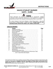
Figure 1 - Nucor Auburn pusher furnace<br />
www.hauckburner.com
2 • A Success Story - June 2006<br />
One example is Nucor Steel’s mill<br />
facility’s latest pusher reheat furnace<br />
incorporating state-of-the-art TriOx<br />
burners. From the outset, the furnace<br />
design had to be capable of<br />
energy consumption of less than 1<br />
MMBtu/ton of steel at production<br />
rates up to 120 tons/hr, a significant<br />
increase from the mill’s prior reheat<br />
furnace capacity. It also had to<br />
comply with ultra-low NOx emissions<br />
requirements which are continuously<br />
monitored by a dedicated<br />
Continuous Emissions Monitoring<br />
(CEM) system.<br />
Background<br />
Nucor’s furnace, built by Forni<br />
Industriali Bendotti S.p.A., is a 60 ft<br />
long pusher reheat furnace rated for<br />
120 tons/hr with peel bar discharge.<br />
It incorporates a recuperator for preheated<br />
combustion air to all burners<br />
operated via a mass flow<br />
control/PLC system.<br />
The primary mill products include<br />
rebar, merchant bar quality; rounds,<br />
squares, flats, angles, and channels;<br />
as well as special bar quality<br />
steels in over 130 sizes of various<br />
grades and chemistries and produced<br />
from 100% recycled scrap.<br />
The reheat furnace replaced an<br />
older unit with nominal capacities of<br />
50 tons/hr up to 95 tons/hr with a<br />
hot charge and a maximum billet<br />
length of only 14 ft.<br />
The new furnace is approximately<br />
42 ft wide and includes a total of 22<br />
TriOx burners divided into four zones<br />
of control (Figure 1). There are six<br />
burners in the bottom heat zone<br />
side-fired and directly opposed to<br />
one another and each rated for a<br />
nominal capacity of 12.3 MMBtu/hr<br />
with hot air. Similarly, there are six<br />
burners above the pass line in the<br />
top heat zone also directly opposed<br />
and rated at a nominal capacity of<br />
9.6 MMBtu/hr each. Finally, the<br />
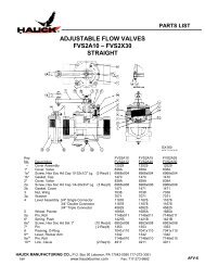
Figure 2 - TriOx Burner<br />
soak zone is end-fired with a total<br />
of ten burners subdivided into two<br />
zones of five each with burners<br />
rated at a nominal capacity of 2.7<br />
MMBtu/hr each. Further, the<br />
furnace height above and below the<br />
pass line is 6 ft 6 in with the burners<br />
offset away from the pass line to<br />
promote combustion burnout and<br />
reduce scale formation.<br />
The furnace design includes provisional<br />
ports for four additional burners,<br />
two in the top heat and two in<br />
the bottom heat zones, to increase<br />
furnace capacity in the future. For<br />
maximum system efficiency and<br />
temperature uniformity, the furnace<br />
design includes both top and bottom<br />
flues. Typical billet size is 6.25 in<br />
square by 40 ft long. As with most<br />
combustion systems, the entire<br />
furnace design including burner<br />
placement is critical for overall heat<br />
transfer and combustion system<br />
efficiency. With the distributed combustion<br />
or Invisiflame® TriOx technology,<br />
furnace design can directly<br />
influence overall NOx production.<br />
The burner’s port geometry and<br />
placement in the furnace wall is very<br />
important to ensure maximum flue<br />
gas entrainment into the flame root<br />
for maximum NOx reduction.<br />
Prior to obtaining the purchase order<br />
for this project, Hauck conducted<br />
a detailed Fluent® Computational<br />
Fluid Dynamics (CFD) analysis of the<br />
furnace heat zones.<br />
Those results were combined with<br />
previous individual burner CFD<br />
modeling and experimental laboratory<br />
data to calculate heat transfer<br />
performance, temperature uniformity,<br />
flow and velocity fields, as well as<br />
expected NOx emissions.<br />
The burner (Figure 2) incorporates<br />
three stages of combustion air to<br />
minimize NOx formation while<br />
maximizing production efficiency<br />
with high temperature preheated<br />
air. The staged air flow is further<br />
controlled by a burner switching<br />
valve, also shown, that proportions<br />
the correct amount of air to each<br />
burner stage, dependent on furnace<br />
temperature. For temperatures<br />
above about 1,600°F, or Invisiflame®<br />
operation, the air flow is heavily<br />
staged for minimal NOx production.<br />
However, at lower furnace temperatures,<br />
which might exist following<br />
normal furnace shutdown or maintenance<br />
periods, the extreme air<br />
staging taking place at high<br />
temperatures is inappropriate as<br />
large levels of unburned<br />
Hydrocarbons (HC) or Carbon<br />
Monoxide (CO) could result.<br />
Copyright © 2009 <strong>Elster</strong> Group
3 • A Success Story - June 2006<br />
Therefore, via the appropriate thermocouple<br />
input, the furnace PLC<br />
simply provides an output signal to<br />
the burner switching valve control<br />
motor to place the valve in the<br />
appropriate position for optimal performance<br />
and emissions control.<br />
The burner is capable of low excess<br />
air operation typically 5% with mass<br />
flow control, throughout its entire<br />
operating range. Fuel efficiency can<br />
be maximized over a full range of<br />
production rate demands.<br />
The geometry of the burner largely<br />
dictates the flame structure, efficiency<br />
of burning, heat transfer, and<br />
NOx formation. The burner features<br />
central fuel injection surrounded by<br />
multiple levels of carefully controlled<br />
air staging, to ensure carbon<br />
monoxide (CO) burnout and flame<br />
stability during cold furnace startups<br />
while simultaneously minimizing<br />
NOx emissions. Optimal fuel and<br />
air inlet port geometries combined<br />
with controlled air staging and hot<br />
air discharge velocities in the 200<br />
ft/s range cause the flame zone to<br />
stretch and entrain large amounts of<br />
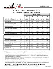
furnace flue gases. As illustrated in<br />
Figure 3, peak flame temperatures<br />
are significantly lower than in conventional<br />
combustion techniques<br />
with subsequent ultra low NOx<br />
emissions achievable even with<br />
preheated combustion air.<br />
Experimental testing of the burner at<br />
high fire and with 2,060°F (1127ºC)<br />
chamber temperatures with preheated<br />
combustion air of 800°F<br />
(427ºC) resulted in NOx emissions of<br />
approximately 34 ppmvd at 3% O2<br />
(0.037 lbs/MMBtu).<br />
Results<br />
<strong>Furnace</strong> commissioning took place<br />
in April, 2005 with an extended dryout<br />
period followed by immediate<br />
production.<br />
Figure 3 - TriOx burner temperature profile<br />
The following data were collected<br />
during normal pusher furnace<br />
operations:<br />
• Load type, size, and weight<br />
• <strong>Furnace</strong> production rate<br />
• Billet surface temperature at<br />
furnace discharge<br />
• <strong>Furnace</strong> zone temperature set<br />
points<br />
• <strong>Furnace</strong> temperatures<br />
• Natural gas and combustion air<br />
flow rates by zone<br />
• Emissions of NOx, CO, and O2<br />
Table 1. Production <strong>Data</strong><br />
<strong>Furnace</strong> operational data downloaded<br />
at maximum production<br />
from the PLC are presented in<br />
Table 1.<br />
<strong>Furnace</strong> Production Rate 140 Ton/hr<br />
N. Gas Gross Heating Value 1,031 Btu/scf<br />
N. Gas Total Flow Rate 117,960 scfh<br />
<strong>Furnace</strong> Firing Rate 121.6 MMBtu/hr<br />
Combustion Air Preheat Temperature 827 (442) ºF (ºC)<br />
Flue Gas Exhaust Temperature 1444 (785) ºF (ºC)<br />
Billet Discharge Temperature 2014 (1100) ºF (ºC)<br />
Overall Excess Air 5 %<br />
Copyright © 2009 <strong>Elster</strong> Group
4 • A Success Story - June 2006<br />
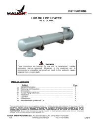
<strong>Furnace</strong> outer wall temperatures<br />
were also measured for furnace heat<br />
losses calculations. Billet surface<br />
and centerline temperatures were<br />
calculated based on the furnace<br />
temperature profile using proprietary<br />
heat transfer software and are<br />
shown in Figure 4.<br />
The billet heating process occurs<br />
smoothly with a mean rate of 17.7<br />
°F/min. in the middle of the heating<br />
zones and 4 °F/min. in the soak<br />
zones. The overall furnace design<br />
including burner positioning, port<br />
geometry and spacing provides<br />
good furnace temperature uniformity<br />
and heat transfer to the metal<br />
being heated. <strong>Furnace</strong> production<br />
rates of 140 tons/hr are common<br />
despite the original design rating of<br />
only 120 tons/hr.<br />
FLUENT® CFD software was utilized<br />
to obtain detailed furnace temperature<br />
distributions. The temperature<br />
distribution in the horizontal sections<br />
via the burners is shown in Figure 5.<br />
Only one half of the furnace width is<br />
shown in Figure 5 for better clarity.<br />
The products of combustion (POC’s)<br />
from the soak zone are included in<br />
the model and flow from right to left;<br />
only a minor influence of soak zone<br />
POC’s is seen on the flames with<br />
mild distortion in the downstream<br />
direction. Simulation results show<br />
that high temperature regions are<br />
located primarily inside the burner<br />
tiles and occupy very small volumes<br />
with short residence times leading<br />
to very low NOx production. Overall<br />
heat or flame distribution patterns in<br />
the near burner zones are very similar<br />
to single burner modeling results<br />
which were validated via laboratory<br />
experiment. Temperature uniformity<br />
of the POC gases across the furnace<br />
width is quite good; the local maximums<br />
at the flames result in elevated<br />
temperature regions close to the<br />
furnace top and bottom walls.<br />
Figure 4 - Temperature profiles<br />
Figure 5 - Temperature profile in horizontal plane via burner centerlines<br />
Billet temperature uniformity and<br />
long term successful billet rolling<br />
further support Fluent® results.<br />
An overall furnace heat balance<br />
was computed (Table 2) based on<br />
the data collected.<br />
Table 2 - <strong>Pusher</strong> furnace heat balance<br />
Input MMBtu/hr % Output MMBtu/hr %<br />
Heat from Fuel 121.6 87.1 Heat of Product 91.2 65.8<br />
Heat of Preheated Air 16.9 12.9 Heat of Flue Gas 40.0 29<br />
<strong>Furnace</strong> Walls Heat Loss 1.1 0.7<br />
Heat of Water Cooling 6.2 4.5<br />
Total 138.5 100 Total 138.5 100<br />
Copyright © 2009 <strong>Elster</strong> Group
5 • A Success Story - June 2006<br />
The preheated combustion air of<br />
827°F (442 ºC) accounts for about<br />
13% of the total furnace heat input.<br />
<strong>Furnace</strong> wall losses are very low at<br />
less than 1% of total heat input.<br />
Overall furnace performance is quite<br />
good considering the heat absorbed<br />
by the steel represents 75% of the<br />
heat from fuel input or about 66% of<br />
the total heat input if including preheated<br />
combustion air. Furthermore,<br />
specific fuel consumption of 868,000<br />
Btu/ton is well below the design target<br />
of approximately 1 MMBtu/ton.<br />
Emissions, as monitored by the<br />
CEM, have remained well below<br />
the permitted threshold throughout<br />
the furnace operation including<br />
production rates from less than 60<br />
tons/hr to 140 tons/hr as well as<br />
during cold furnace startups following<br />
prolonged mill shutdowns. At<br />
the maximum production rate of 140<br />
tons/hr reported here, NOx emissions<br />
of less than 0.052 lbs/MMBtu<br />
were recorded with air preheats<br />
exceeding 800°F (427ºC). At lower<br />
production rates and slightly lower<br />
air preheat levels, NOx emissions<br />
less than 0.045 lbs/MMBtu were<br />
commonly recorded. Furthermore<br />
CO emissions are virtually zero<br />
during any operating conditions.<br />
Conclusion<br />
Remaining cost competitive in the<br />
face of higher fuel and raw material<br />
prices combined with increasing<br />
market competition are the challenges<br />
faced by every major steel<br />
producer. In the case of Nucor<br />
Auburn’s pusher reheat furnace,<br />
the desired method to achieve these<br />
goals included a state of the art<br />
furnace, control system, and burners<br />
utilizing preheated combustion air,<br />
but with very stringent environmental<br />
regulatory requirements.<br />
Regulatory requirement for ultra<br />
low NOx emissions, as well as<br />
Nucor’s goals of increasing furnace<br />
production, reducing specific fuel<br />
consumption, and minimizing scale<br />
formation, were ultimately achieved<br />
and proven in practice with the<br />
application of Hauck’s Invisiflame®<br />
TriOx burner technology. Close collaboration<br />
between furnace builder,<br />
end customer, and burner supplier<br />
combined with state of the art CFD<br />
modeling to optimize burner design,<br />
placement in the furnace, and burner<br />
port geometry have ensured long<br />
term success.<br />
For more information, contact Hauck<br />
Manufacturing Company at<br />
PO Box 90, Lebanon, PA 17042<br />
Phone: 717-272-3051<br />
email hauck@hauckburner.com<br />
or visit www.hauckburner.com<br />
To date, rolling operations are running<br />
smoothly, production rates have exceeded<br />
design targets while simultaneously beating<br />
specific fuel consumption targets, and<br />
NOx emission are well within regulatory<br />
requirements.<br />
Authors:<br />
James Feese, P.E.<br />
Director of Product Development<br />
Dr. Felix Lisin<br />
Director of Applied Research<br />
Copyright © 2009 <strong>Elster</strong> Group