O & M Manual for the Eaton ATC-100 Automatic Transfer Switch ...
O & M Manual for the Eaton ATC-100 Automatic Transfer Switch ...
O & M Manual for the Eaton ATC-100 Automatic Transfer Switch ...

You also want an ePaper? Increase the reach of your titles
YUMPU automatically turns print PDFs into web optimized ePapers that Google loves.
O & M <strong>Manual</strong> <strong>for</strong> <strong>the</strong> <strong>Eaton</strong><br />
<strong>ATC</strong>-<strong>100</strong> <strong>Automatic</strong> <strong>Transfer</strong> <strong>Switch</strong><br />
Controller<br />
Instructional Booklet<br />
New In<strong>for</strong>mation<br />
Description<br />
Page<br />
1. Introduction . . . . . . . . . . . . . . . . . . . . . . . . . . . . . . . 2<br />
2. Hardware Description . . . . . . . . . . . . . . . . . . . . . . . . 5<br />
3. Operation . . . . . . . . . . . . . . . . . . . . . . . . . . . . . . . . . 9<br />
4. Programming . . . . . . . . . . . . . . . . . . . . . . . . . . . . . . 11<br />
5. Troubleshooting and Maintenance . . . . . . . . . . . . . . . . 12<br />
Appendix A: Operational Flowchart . . . . . . . . . . . . . . . . . 14<br />
IB01602019E<br />
For more in<strong>for</strong>mation visit: www.eatonelectrical.com
Instructional Booklet<br />
Page 2 Effective: May 2006<br />
O&M <strong>Manual</strong> <strong>for</strong> <strong>the</strong> <strong>Eaton</strong> <strong>ATC</strong>-<strong>100</strong><br />
<strong>Automatic</strong> <strong>Transfer</strong> <strong>Switch</strong> Controller<br />
Section1: Introduction<br />
CAUTION<br />
THE <strong>ATC</strong>-<strong>100</strong> CONTROLLER IS FACTORY PROGRAMMED FOR A<br />
SPECIFIC AUTOMATIC TRANSFER SWITCH. DO NOT ATTEMPT TO<br />
INTERCHANGE <strong>ATC</strong>-<strong>100</strong> CONTROL DEVICES WITHOUT CONSULT-<br />
ING EATON ELECTRICAL, INC.<br />
All possible contingencies that may arise during installation, operation,<br />
or maintenance, and all details and variations of this equipment<br />
do no purport to be covered by <strong>the</strong>se instructions. If fur<strong>the</strong>r<br />
in<strong>for</strong>mation is desired by <strong>the</strong> purchaser regarding an installation,<br />
operation, or maintenance of particular equipment, please contact<br />
an authorized <strong>Eaton</strong> Electrical Sales Representative or <strong>the</strong> installing<br />
contractor.<br />
1.1 Preliminary Comments and Safety Precautions<br />
This technical document is intended to cover most aspects associated<br />
with <strong>the</strong> installation, application, operation, and maintenance<br />
of <strong>the</strong> <strong>Automatic</strong> <strong>Transfer</strong> Controller (<strong>ATC</strong>-<strong>100</strong>). It is provided as<br />
a guide <strong>for</strong> authorized and qualified personnel only in <strong>the</strong> selection<br />
and application of <strong>the</strong> <strong>ATC</strong>-<strong>100</strong>. Please refer to <strong>the</strong> specific<br />
WARNING and CAUTION in Section 1.1.2 be<strong>for</strong>e proceeding. If<br />
fur<strong>the</strong>r in<strong>for</strong>mation is required by <strong>the</strong> purchaser regarding a particular<br />
installation, application, or maintenance activity, please contact<br />
an authorized <strong>Eaton</strong>, Electrical sales representative or <strong>the</strong><br />
installing contractor.<br />
1.1.1 Warranty and Liability In<strong>for</strong>mation<br />
No warranties, expressed or implied, including warranties of fitness<br />
<strong>for</strong> a particular purpose of merchantability, or warranties arising<br />
from course of dealing or usage of trade, are made regarding<br />
<strong>the</strong> in<strong>for</strong>mation, recommendations and descriptions contained<br />
herein. In no event will <strong>Eaton</strong> be responsible to <strong>the</strong> purchaser or<br />
user in contract, in tort (including negligence), strict liability or<br />
o<strong>the</strong>rwise <strong>for</strong> any special, indirect, incidental or consequential<br />
damage or loss whatsoever, including but not limited to damage or<br />
loss of use of equipment, plant or power system, cost of capital,<br />
loss of power, additional expenses in <strong>the</strong> use of existing power<br />
facilities, or claims against <strong>the</strong> purchaser or user by its customers<br />
resulting from <strong>the</strong> use of <strong>the</strong> in<strong>for</strong>mation and descriptions contained<br />
herein.<br />
1.1.2 Safety Precautions<br />
All safety codes, safety standards, and/or regulations must be<br />
strictly observed in <strong>the</strong> installation, operation, and maintenance of<br />
this device.<br />
WARNING<br />
THE WARNINGS AND CAUTIONS INCLUDED AS PART OF THE PRO-<br />
CEDURAL STEPS IN THIS DOCUMENT ARE FOR PERSONNEL SAFETY<br />
AND PROTECTION OF THE EQUIPMENT FROM DAMAGE. AN EXAM-<br />
PLE OF A TYPICAL WARNING HEADING IS SHOWN ABOVE TO<br />
FAMILIARIZE PERSONNEL WITH THE STYLE OF PRESENTATION.<br />
THIS WILL HELP TO INSURE THAT PERSONNEL ARE ALERT TO<br />
WARNINGS, WHICH APPEAR THROUGHOUT THE DOCUMENT. IN<br />
ADDITION, WARNINGS AND CAUTIONS ARE ALL UPPER CASE AND<br />
BOLDFACE.<br />
WARNING<br />
COMPLETELY READ AND UNDERSTAND THE MATERIAL PRE-<br />
SENTED IN THIS DOCUMENT BEFORE ATTEMPTING INSTALLATION,<br />
APPLICATION, OPERATION, OR MAINTENANCE OF THE EQUIP-<br />
MENT. IN ADDITION, ONLY QUALIFIED PERSONS SHOULD BE PER-<br />
MITTED TO PERFORM ANY WORK ASSOCIATED WITH THIS<br />
EQUIPMENT. ANY WIRING INSTRUCTIONS PRESENTED IN THIS<br />
DOCUMENT MUST BE FOLLOWED PRECISELY. FAILURE TO DO SO<br />
COULD CAUSE PERMANENT EQUIPMENT DAMAGE.<br />
1.2 Background<br />
<strong>Transfer</strong> switches are used to protect critical electrical loads<br />
against loss of power. The load’s utility power source is backed<br />
up by a generator power source. A transfer switch is connected<br />
to both <strong>the</strong> utility and generator power sources and supplies <strong>the</strong><br />
load with power from one of <strong>the</strong> two sources. In <strong>the</strong> event that<br />
power is lost from <strong>the</strong> utility, <strong>the</strong> transfer switch transfers <strong>the</strong><br />
load to <strong>the</strong> generator power source. Once utility power is<br />
restored, <strong>the</strong> load is automatically transferred back to <strong>the</strong> utility<br />
power source.<br />
In <strong>Automatic</strong> <strong>Transfer</strong> <strong>Switch</strong> (ATS) equipment, <strong>the</strong> switch’s intelligence<br />
system initiates <strong>the</strong> transfer when <strong>the</strong> utility power falls<br />
below or rises above a preset voltage or frequency. The ATS initiates<br />
generator start up <strong>the</strong>n transfers to <strong>the</strong> generator power<br />
source when sufficient generator voltage is available. When utility<br />
power is restored, <strong>the</strong> ATS automatically transfers back to <strong>the</strong><br />
utility power source and initiates generator engine shutdown.<br />
An ATS consists of three basic elements:<br />
1. Main contacts to connect and disconnect <strong>the</strong> load to and from<br />
<strong>the</strong> power sources.<br />
2. A mechanism to transfer <strong>the</strong> main contacts from source to<br />
source.<br />
3. Intelligence/supervisory circuits to constantly monitor <strong>the</strong> condition<br />
of <strong>the</strong> power sources and thus provide <strong>the</strong> intelligence<br />
necessary <strong>for</strong> <strong>the</strong> switch and related circuit operation.<br />
This manual deals with <strong>the</strong> third basic element of <strong>the</strong> ATS, <strong>the</strong><br />
required intelligence/supervisory circuits. Earlier ATSs were controlled<br />
by relay logic type or a solid-state, single-board controllers.<br />
In ei<strong>the</strong>r case, <strong>the</strong> control panel consisted of a number of individually<br />
mounted and wired devices offering a limited amount of system<br />
flexibility, especially in <strong>the</strong> case of <strong>the</strong> relay logic design. The<br />
<strong>ATC</strong>-<strong>100</strong> advances <strong>the</strong> application of intelligence, supervisory,<br />
and programming capabilities <strong>for</strong> ATS equipment.<br />
1.3 Product Overview<br />
The <strong>ATC</strong>-<strong>100</strong> is a comprehensive, multi-function, microprocessor<br />
based ATS controller. It is a compact, self-contained, panel<br />
mounted device designed to replace traditional relay and solidstate<br />
logic panels.<br />
Designed to meet <strong>the</strong> needs of markets worldwide, <strong>the</strong> <strong>ATC</strong>-<strong>100</strong>:<br />
• Is an Underwriters Laboratories (UL) recognized component<br />
• Complies with UL <strong>100</strong>8/ Canadian Standards Association (CSA)<br />
22.2-178<br />
• Complies with UL 991 environmental tests<br />
• Complies with International Electrotechnical Commission (IEC)<br />
6<strong>100</strong>0-4-2, 6<strong>100</strong>0-4-3, 6<strong>100</strong>0-4-4, 6<strong>100</strong>0-4-5, 6<strong>100</strong>0-4-6,<br />
and 6<strong>100</strong>0-4-11<br />
For more in<strong>for</strong>mation visit: www.eatonelectrical.com<br />
IIB01602019E
O&M <strong>Manual</strong> <strong>for</strong> <strong>the</strong> <strong>Eaton</strong> <strong>ATC</strong>-<strong>100</strong><br />
<strong>Automatic</strong> <strong>Transfer</strong> <strong>Switch</strong> Controller<br />
Instructional Booklet<br />
Effective: May 2006 Page 3<br />
• Complies with Comité Internationale Spécial des Perturbations<br />
Radioelectrotechnique (CISPR) 11, Class B<br />
• Complies with Federal Communications Commission (FCC) Part<br />
15, Class B<br />
• Meets European Standards Con<strong>for</strong>mance (CE mark)<br />
The <strong>ATC</strong>-<strong>100</strong> provides an unmatched degree of programmed flexibility<br />
to address <strong>the</strong> needs of any system. It operates from system<br />
voltages between 120 and 480 Vac, single-phase or 3-phase,<br />
at 50 or 60 Hz. In addition, a period of no control power operation<br />
is provided. The <strong>ATC</strong>-<strong>100</strong> monitors <strong>the</strong> condition of <strong>the</strong><br />
3-phase line-to-line voltage and frequency of both <strong>the</strong> utility and<br />
generator power sources. It can also be set up <strong>for</strong> single-phase<br />
operation. The <strong>ATC</strong>-<strong>100</strong> provides <strong>the</strong> necessary intelligence to<br />
insure that <strong>the</strong> transfer switch operates properly through a series<br />
of programmed sensing and timing functions.<br />
A standard <strong>ATC</strong>-<strong>100</strong> will:<br />
• Monitor utility and generator power source voltages and generator<br />
power source frequency<br />
• Provide undervoltage protection of <strong>the</strong> utility and generator<br />
power sources<br />
• Provide underfrequency and overfrequency protection of <strong>the</strong><br />
generator power source<br />
• Permit easy customer set up<br />
• Permit system testing<br />
• Provide faceplate source status indications<br />
1.4 Glossary<br />
With respect to <strong>the</strong>ir use within this document and as <strong>the</strong>y relate<br />
to ATS and controller operation, <strong>the</strong> following terminology is<br />
defined.<br />
Available<br />
A source is defined as “available” when it is within its undervoltage<br />
/ underfrequency/overfrequency (if applicable) set-point<br />
ranges <strong>for</strong> <strong>the</strong> nominal voltage and frequency setting.<br />
Connected<br />
Connected is defined as when <strong>the</strong> input is shorted by an external<br />
contact or connection.<br />
Failed or Fails<br />
A source is defined as “failed” when it is outside of <strong>the</strong> applicable<br />
voltage and frequency set-point ranges <strong>for</strong> <strong>the</strong> nominal voltage<br />
and frequency setting <strong>for</strong> a time exceeding 0.5 seconds after <strong>the</strong><br />
time delay emergency fail (TDEF) time delays expires.<br />
Failsafe<br />
Failsafe is a feature that prevents disconnection from <strong>the</strong> only<br />
available power source and also <strong>for</strong>ces a transfer or re-transfer<br />
operation to <strong>the</strong> only available power source.<br />
Re-<strong>Transfer</strong><br />
Re-transfer is defined as a change of <strong>the</strong> load connection from <strong>the</strong><br />
generator to <strong>the</strong> utility.<br />
Utility<br />
Utility is <strong>the</strong> primary source (normal source, normal power source,<br />
or normal).<br />
Generator<br />
Generator is <strong>the</strong> secondary source (emergency source, emergency<br />
power source, emergency, standby, or backup source).<br />
Utility: Failed or Fails<br />
Utility is defined as “failed” when it is outside of its undervoltage<br />
set-point range <strong>for</strong> <strong>the</strong> nominal voltage setting.<br />
Generator: Failed or Fails<br />
Generator is defined as “failed” when it is outside of its undervoltage/<br />
underfrequency/overfrequency (if applicable) set-point ranges<br />
<strong>for</strong> <strong>the</strong> nominal voltage and frequency setting <strong>for</strong> a time exceeding<br />
0.5 seconds after <strong>the</strong> TDEF time delay expires.<br />
<strong>Switch</strong>ing Device<br />
A switching device is used to change available power sources to a<br />
common load. (i.e. circuit breaker, molded case switch, power<br />
contactor)<br />
<strong>Transfer</strong><br />
<strong>Transfer</strong> is defined as a change of <strong>the</strong> load connection from <strong>the</strong><br />
utility to <strong>the</strong> generator power source.<br />
Unconnected<br />
Unconnected is defined as when <strong>the</strong> input is not shorted by an<br />
external contact or connection.<br />
V IN, RMS<br />
Refers to <strong>the</strong> operating input voltage (Vac, RMS).<br />
1.5 Functions/Features/Options<br />
The primary function of <strong>ATC</strong>-<strong>100</strong> is to accurately monitor power<br />
sources and provide <strong>the</strong> necessary intelligence to operate an ATS<br />
in an appropriate and timely manner. In addition, <strong>the</strong> <strong>ATC</strong>-<strong>100</strong><br />
provides status in<strong>for</strong>mation through <strong>the</strong> device’s faceplate.<br />
1.5.1 Operational Simplicity<br />
From installation to programming to usage, <strong>the</strong> <strong>ATC</strong>-<strong>100</strong> was<br />
designed with operational simplicity in mind. Only one style needs<br />
to be considered, regardless of input/output requirements or system<br />
voltages and frequencies. The <strong>ATC</strong>-<strong>100</strong> provides <strong>the</strong> functionality<br />
of numerous o<strong>the</strong>r devices combined in one package that<br />
mounts in 6.5 by 8.5 in. (165.1 by 215.9 mm) of panel space.<br />
1.5.2 Features<br />
The following is a list of <strong>the</strong> features of <strong>the</strong> <strong>ATC</strong>-<strong>100</strong>.<br />
1. Time Delay Normal to Emergency (TDNE)<br />
This feature provides a time delay when transferring from <strong>the</strong><br />
utility source to <strong>the</strong> generator power source. Timing begins<br />
when <strong>the</strong> generator source becomes available. It permits controlled<br />
transfer of <strong>the</strong> load circuit to <strong>the</strong> generator source.<br />
Jumper selectable at 2 or 15 seconds.<br />
2. Time Delay on Engine Starting (TDES)<br />
This feature provides a time delay of <strong>the</strong> signal to initiate <strong>the</strong><br />
engine/generator start cycle in order to override momentary<br />
power outages or voltage fluctuations of <strong>the</strong> utility source.<br />
Fixed setting of three seconds<br />
3. Time Delay Emergency to Normal (TDEN)<br />
This feature provides a time delay of <strong>the</strong> re-transfer operation<br />
to permit stabilization of <strong>the</strong> utility source. Timing begins<br />
when <strong>the</strong> utility source becomes available. If <strong>the</strong> generator<br />
source fails during timing, <strong>the</strong>n a re-transfer is immediate,<br />
overriding <strong>the</strong> time delay.<br />
Fixed setting of five minutes.<br />
4. Time Delay <strong>for</strong> Engine Cool-down (TDEC)<br />
This feature provides a time delay of <strong>the</strong> signal to initiate <strong>the</strong><br />
engine/generator stop cycle after <strong>the</strong> re-transfer operation.<br />
This allows <strong>the</strong> engine/generator to cool down by running<br />
unloaded. Timing begins on completion of <strong>the</strong> re-transfer<br />
cycle.<br />
Fixed setting of five minutes.<br />
IB01602019E<br />
For more in<strong>for</strong>mation visit: www.eatonelectrical.com
Instructional Booklet<br />
Page 4 Effective: May 2006<br />
O&M <strong>Manual</strong> <strong>for</strong> <strong>the</strong> <strong>Eaton</strong> <strong>ATC</strong>-<strong>100</strong><br />
<strong>Automatic</strong> <strong>Transfer</strong> <strong>Switch</strong> Controller<br />
5. Generator Monitoring and Protection<br />
This feature provides monitoring and protection based on <strong>the</strong><br />
generator voltage and/or frequency set points. All Feature<br />
5 functions are “failsafe” operations.<br />
5B. Single Phase Undervoltage and Underfrequency Protection<br />
Undervoltage:<br />
Dropout: 80% of nominal<br />
Pickup: 90% of nominal<br />
Underfrequency:<br />
Dropout: 90% of nominal<br />
Pickup: 95% of nominal<br />
5C. 1-Phase Overfrequency<br />
Overfrequency:<br />
Dropout: 115% of nominal<br />
Pickup: 110% of nominal<br />
5N. All Phase Overfrequency<br />
Overfrequency:<br />
Dropout: 115% of nominal<br />
Pickup: 110% of nominal<br />
5J. 3-Phase Undervoltage and Underfrequency Protection<br />
Undervoltage:<br />
Dropout: 80% of nominal<br />
Pickup: 90% of nominal<br />
Underfrequency:<br />
Dropout: 90% of nominal<br />
Pickup: 95% of nominal<br />
6. Test Operators<br />
<strong>Eaton</strong> automatic transfer switch controllers are provided with<br />
a “System Test” pushbutton.<br />
6B. System Test Pushbutton<br />
The System Test pushbutton will start <strong>the</strong> generator, transfer<br />
<strong>the</strong> load to <strong>the</strong> generator source, run on generator <strong>for</strong> a run<br />
time of 15 minutes, and <strong>the</strong>n re-transfer back to <strong>the</strong> utility<br />
source. All programmed time delays (TDNE, TDEN, etc.) will<br />
be per<strong>for</strong>med as part of <strong>the</strong> System Test. The System Test<br />
is failsafe protected.<br />
7. Time Delay Emergency Fail (TDEF)<br />
This feature provides a time delay that prevents a connected<br />
emergency source from being declared “failed” in order to<br />
override momentary generator fluctuations. If <strong>the</strong> generator<br />
power source remains in <strong>the</strong> failed state <strong>the</strong>n, 0.5 seconds<br />
after <strong>the</strong> TDEF timer expires, <strong>the</strong> transfer switch will proceed<br />
with <strong>the</strong> programmed sequence <strong>for</strong> re-transfer.<br />
Fixed setting of six seconds<br />
12. Power Source Annunciation<br />
12C.Utility - Source Connected<br />
This feature provides a green LED that, when lit, indicates<br />
that <strong>the</strong> load is connected to <strong>the</strong> utility source.<br />
12D.Generator - Source Connected<br />
This feature provides a red LED that, when lit, indicates <strong>the</strong><br />
load is connected to <strong>the</strong> generator source.<br />
Power Source Availability<br />
Provides LED’s to indicate if a power source is available.<br />
LED’s may be integral or separate from <strong>the</strong> controller.<br />
12G.Utility - Available<br />
This feature provides a white LED that, when lit, indicates<br />
that <strong>the</strong> utility source is available.<br />
12H.Generator - Available<br />
This feature provides an amber LED that, when lit, indicates<br />
that <strong>the</strong> generator source is available.<br />
23. Generator Test<br />
This feature provides a means <strong>for</strong> automatic testing of <strong>the</strong><br />
engine/generator set or standby power system. All programmed<br />
time delays will be per<strong>for</strong>med during generator test<br />
operations.<br />
23K.Generator Test Selectable – Off / 7 / 14 / 28 Day Interval<br />
This feature provides <strong>for</strong> automatic test operation of <strong>the</strong> generator.<br />
Available test cycles are 7, 14, or 28 days with a<br />
15-minute duration.<br />
Programmable jumpers allow <strong>for</strong> selection of three test<br />
cycles:<br />
• Generator Start/Run Only (No Load);<br />
• Generator Test with Load <strong>Transfer</strong>; or<br />
• Disabled<br />
This is a “Failsafe” operation.<br />
26. Utility - Monitoring and Protection<br />
This feature provides utility monitoring and protection functions.<br />
If <strong>the</strong> utility power source fails, <strong>the</strong>n <strong>the</strong> <strong>ATC</strong>-<strong>100</strong> will<br />
begin <strong>the</strong> sequence of operations necessary to transfer <strong>the</strong><br />
load circuit to <strong>the</strong> generator power source. All Feature 26<br />
monitoring and protection functions are “failsafe” operations.<br />
26P.All Phase Undervoltage Protection<br />
This feature provides all phase undervoltage monitoring and<br />
protection.<br />
Undervoltage:<br />
Dropout: 80% of nominal<br />
Pickup: 90% of nominal<br />
This feature provides LED’s to indicate switch position and<br />
power source availability indications.<br />
<strong>Switch</strong> Position<br />
Provides LED’s to indicate <strong>the</strong> transfer switch position.<br />
For more in<strong>for</strong>mation visit: www.eatonelectrical.com<br />
IIB01602019E
O&M <strong>Manual</strong> <strong>for</strong> <strong>the</strong> <strong>Eaton</strong> <strong>ATC</strong>-<strong>100</strong><br />
<strong>Automatic</strong> <strong>Transfer</strong> <strong>Switch</strong> Controller<br />
Instructional Booklet<br />
Effective: May 2006 Page 5<br />
Section 2: Hardware Description<br />
2.1 General<br />
The purpose of this section is to familiarize <strong>the</strong> reader with <strong>the</strong><br />
<strong>ATC</strong>-<strong>100</strong> hardware, its nomenclature, and to list <strong>the</strong> unit’s specifications.<br />
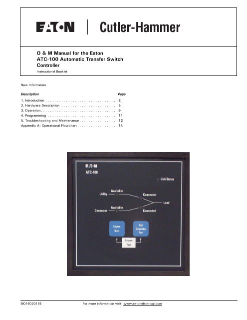
2.2 Front (Operator) Panel<br />
The front panel, depending on <strong>the</strong> installation, is normally accessible<br />
from <strong>the</strong> outside of a panel or door. The front panel provides a<br />
means to:<br />
• alert <strong>the</strong> user to specific conditions;<br />
• per<strong>for</strong>m an Engine Start;<br />
• per<strong>for</strong>m a System Test; and<br />
• program a Generator Test.<br />
The <strong>ATC</strong>-<strong>100</strong> front panel serves two primary functions: output<br />
and input (see Figure 1). The output function consists of five LED<br />
outputs:<br />
1. Unit Status;<br />
2. Utility Available;<br />
3. Utility Connected;<br />
4. Generator Available; and<br />
5. Generator Connected.<br />
There are three input functions accessible through <strong>the</strong> pushbuttons:<br />
1. Engine Start;<br />
2. Set Generator Test; and<br />
3. System Test.<br />
UTILITY CONNECTED<br />
UNIT STATUS<br />
UTILITY<br />
AVAILABLE<br />
GENERATOR<br />
CONNECTED<br />
GENERATOR<br />
AVAILABLE<br />
ENGINE START<br />
SET GENERATOR<br />
TEST<br />
SYSTEM TEST<br />
Figure 1. The <strong>ATC</strong>-<strong>100</strong> Front Panel.<br />
IB01602019E<br />
For more in<strong>for</strong>mation visit: www.eatonelectrical.com
Instructional Booklet<br />
Page 6 Effective: May 2006<br />
O&M <strong>Manual</strong> <strong>for</strong> <strong>the</strong> <strong>Eaton</strong> <strong>ATC</strong>-<strong>100</strong><br />
<strong>Automatic</strong> <strong>Transfer</strong> <strong>Switch</strong> Controller<br />
2.2.1 The Output Function LED’s<br />
Unit Status LED<br />
The green Unit Status LED blinks at a rate of once per second<br />
while <strong>the</strong> <strong>ATC</strong>-<strong>100</strong> is operational. This indicates that <strong>the</strong><br />
<strong>ATC</strong>-<strong>100</strong> has completed a self-diagnostic cycle. The self-diagnostic<br />
cycle checks include <strong>the</strong>:<br />
• Microprocessor operation and<br />
• Memory operation.<br />
Utility Available LED<br />
The white Utility Available LED illuminates if <strong>the</strong> utility power<br />
source meets <strong>the</strong> criteria to be considered “available”. That is,<br />
when it is within its undervoltage ranges <strong>for</strong> <strong>the</strong> nominal voltage<br />
setting.<br />
Utility Connected LED<br />
The green Utility Connected LED illuminates when <strong>the</strong> utility<br />
switching device and its associated position indicating auxiliary<br />
contacts are closed.<br />
The Utility Connected LED will blink to indicate an alarm condition<br />
<strong>for</strong> an unsuccessful transfer (see Section 5.2, <strong>ATC</strong>-<strong>100</strong> Troubleshooting).<br />
The Generator Test jumpers can be set to one of three positions to<br />
allow flexibility in how <strong>the</strong> test is run:<br />
• No Load Generator Test;<br />
• Generator Test with Load <strong>Transfer</strong>; or<br />
• Disabled.<br />
For complete in<strong>for</strong>mation on <strong>the</strong> Generator Test function, see Section<br />
3.4.3.<br />
System Test (Engine Start + Set Generator Test Pushbuttons)<br />
Pressing <strong>the</strong> Engine Start and Set Generator Test pushbuttons simultaneously<br />
will initiate a System Test. The System Test will start <strong>the</strong><br />
generator, transfer <strong>the</strong> load to generator, run on generator <strong>for</strong> a<br />
run time of 15 minutes, time out TDEN <strong>for</strong> five minutes, <strong>the</strong>n retransfer,<br />
run <strong>the</strong> engine cool down cycle, and <strong>the</strong>n terminate. To abort <strong>the</strong><br />
System Test, simultaneously press <strong>the</strong> Engine Start and Set Generator<br />
Test pushbuttons.<br />
2.3 Rear Access Area<br />
The rear access area of <strong>the</strong> <strong>ATC</strong>-<strong>100</strong> is normally accessible from<br />
<strong>the</strong> rear of an open panel door (see Figure 2).<br />
Generator Available<br />
The amber Generator Available LED illuminates if <strong>the</strong> generator<br />
power source meets <strong>the</strong> criteria to be considered “available”.<br />
That is, when it is within its undervoltage/underfrequency/overfrequency<br />
(if applicable) ranges <strong>for</strong> <strong>the</strong> nominal voltage and frequency<br />
setting.<br />
The Generator Available LED will blink to indicate an alarm condition<br />
if <strong>the</strong> Generator did not become available within 90 seconds<br />
<strong>for</strong> a System Test, Generator Test, or Engine Start Test, (see Section<br />
5.2, <strong>ATC</strong>-<strong>100</strong> Troubleshooting).<br />
Generator Connected LED<br />
The red Generator Connected LED illuminates when <strong>the</strong> generator<br />
switching device and its associated position indicating auxiliary<br />
contacts are closed.<br />
The Generator Connected LED will blink to indicate an alarm condition<br />
<strong>for</strong> an unsuccessful transfer (see Section 5.2, <strong>ATC</strong>-<strong>100</strong><br />
Troubleshooting).<br />
2.2.2 The Input Function Components<br />
The Pushbuttons and Combinations<br />
Engine Start Pushbutton<br />
Pressing and holding <strong>the</strong> Engine Start pushbutton <strong>for</strong> a period of<br />
five seconds will initiate a No Load Generator Test. The test will<br />
run <strong>for</strong> 15 minutes and <strong>the</strong>n terminate. If <strong>the</strong> Engine Start pushbutton<br />
is pressed while <strong>the</strong> engine/generator is running, <strong>the</strong> test<br />
will terminate.<br />
Set Generator Test Pushbutton<br />
The Set Generator Test pushbutton allows <strong>the</strong> user to test <strong>the</strong><br />
generator automatically on a periodic (every 7, 14, or 28 days)<br />
basis. Pressing and holding <strong>the</strong> Set Generator Test pushbutton <strong>for</strong><br />
a period of five seconds will initiate a Generator Test. The Utility<br />
Available and Generator Available LED’s will flash twice indicating<br />
that <strong>the</strong> Generator Test is programmed.<br />
The Generator Test can be deprogrammed by pressing and holding<br />
<strong>the</strong> Set Generator Test pushbutton <strong>for</strong> a period of five seconds.<br />
The Utility Available and Generator Available LED’s will flash four<br />
times, indicating that <strong>the</strong> Generator Test is no longer programmed.<br />
Figure 2. <strong>ATC</strong>-<strong>100</strong> (Rear View).<br />
All wiring connections to <strong>the</strong> <strong>ATC</strong>-<strong>100</strong> are made at <strong>the</strong> rear of <strong>the</strong><br />
chassis.<br />
Note: To allow <strong>for</strong> uni<strong>for</strong>m identification, <strong>the</strong> frame of reference when discussing<br />
<strong>the</strong> rear access area is with <strong>the</strong> panel door open and <strong>the</strong> User facing<br />
<strong>the</strong> back of <strong>the</strong> <strong>ATC</strong>-<strong>100</strong>.<br />
Located at <strong>the</strong> left rear of <strong>the</strong> <strong>ATC</strong>-<strong>100</strong> are connectors J1, J2,<br />
and J7. J1 and J2 provide <strong>for</strong> voltage monitoring of <strong>the</strong> utility<br />
and generator respectively. J7 is provided <strong>for</strong> utility and generator<br />
control power input. The J4 and J5 connectors are located at <strong>the</strong><br />
bottom of <strong>the</strong> controller. The J4 connector provides connections<br />
<strong>for</strong> <strong>the</strong> control inputs and dry relay contacts <strong>for</strong> primary control<br />
outputs. The J5 connector provides <strong>the</strong> Generator Start dry relay<br />
contacts <strong>for</strong> starting <strong>the</strong> generator (see Figure 3).<br />
See Section 2.5 <strong>for</strong> contact ratings.<br />
For more in<strong>for</strong>mation visit: www.eatonelectrical.com<br />
IIB01602019E
O&M <strong>Manual</strong> <strong>for</strong> <strong>the</strong> <strong>Eaton</strong> <strong>ATC</strong>-<strong>100</strong><br />
<strong>Automatic</strong> <strong>Transfer</strong> <strong>Switch</strong> Controller<br />
Instructional Booklet<br />
Effective: May 2006 Page 7<br />
Reset<br />
Voltage<br />
Control<br />
Power<br />
Utility<br />
Utility<br />
Generator<br />
Generator<br />
J7<br />
120<br />
208<br />
220<br />
230<br />
240<br />
380<br />
415<br />
480<br />
Phases<br />
1φ<br />
3φ<br />
Utility<br />
Generator<br />
Phase C<br />
Phase B<br />
Phase A<br />
Phase C<br />
Phase B<br />
Phase A<br />
J1<br />
J2<br />
Frequency<br />
50 Hz<br />
60 Hz<br />
TDNE<br />
2 sec<br />
15 sec<br />
Overfreq<br />
On<br />
Off<br />
Generator Test<br />
Off<br />
No Load<br />
Load<br />
7 day<br />
14 day<br />
28 day<br />
J4<br />
J5<br />
1 2 3 4 5 6 7 8 1 2<br />
3<br />
DC_Output<br />
Utility Closed<br />
Generator Closed<br />
K1 - (Com)<br />
K1 - (NO)<br />
K2 – (Com)<br />
K2 - (NO)<br />
Earth Ground<br />
Gen Start - (NO)<br />
Gen Start - (Com)<br />
Gen Start - (NC)<br />
Control Inputs<br />
Control Outputs<br />
Generator Start Contacts<br />
Figure 3. Connectors and Jumpers on <strong>the</strong> <strong>ATC</strong>-<strong>100</strong>.<br />
2.3.1 Programming Jumpers<br />
The <strong>ATC</strong>-<strong>100</strong> is programmable via <strong>the</strong> jumpers on <strong>the</strong> back of <strong>the</strong><br />
unit. The jumper selections are discussed in Section 5, Programming.<br />
2.3.2 Reset Pushbutton<br />
The <strong>ATC</strong>-<strong>100</strong> has a Reset pushbutton in <strong>the</strong> top right corner to<br />
reset <strong>the</strong> following alarm conditions:<br />
• “Utility Connected” LED is blinking;<br />
• “Generator Connected” LED is blinking; and<br />
• “Generator Available” LED is blinking.<br />
See Section 5.2, <strong>ATC</strong>-<strong>100</strong> Troubleshooting <strong>for</strong> fur<strong>the</strong>r in<strong>for</strong>mation<br />
on <strong>the</strong>se alarm conditions.<br />
Note: Pressing <strong>the</strong> Reset pushbutton will also clear <strong>the</strong> Generator Test programming.<br />
It will be necessary to set up <strong>the</strong> Generator Test again after<br />
pressing <strong>the</strong> Reset pushbutton.<br />
2.4 Control Inputs<br />
The <strong>ATC</strong>-<strong>100</strong> has two individual control input signals that are<br />
used to sense transfer switch position. The inputs require and<br />
external contact closure to <strong>the</strong> DC_Output pin (J4, Pin1). The<br />
DC_Output pin is connected internally to <strong>the</strong> unregulated DC supply<br />
(26 V) and appropriate current-limiting to provide a nominal<br />
current of 10 mA per channel.<br />
2.4.1 Control Input Descriptions<br />
The Control Input “State” definitions are as follows.<br />
Connected - When <strong>the</strong> input is shorted by an external contact or<br />
connection.<br />
Unconnected - When <strong>the</strong> input is NOT shorted by an external contact<br />
or connection.<br />
The Control Input operations are defined as follows.<br />
IB01602019E<br />
For more in<strong>for</strong>mation visit: www.eatonelectrical.com
Instructional Booklet<br />
Page 8 Effective: May 2006<br />
O&M <strong>Manual</strong> <strong>for</strong> <strong>the</strong> <strong>Eaton</strong> <strong>ATC</strong>-<strong>100</strong><br />
<strong>Automatic</strong> <strong>Transfer</strong> <strong>Switch</strong> Controller<br />
Utility Closed<br />
When this input (J4, Pin 2) is in <strong>the</strong> “Connected” state, it indicates<br />
to <strong>the</strong> <strong>ATC</strong>-<strong>100</strong> that <strong>the</strong> utility switching device is closed.<br />
When this input is in <strong>the</strong> “Unconnected” state, it indicates to <strong>the</strong><br />
<strong>ATC</strong>-<strong>100</strong> that <strong>the</strong> utility switching device is open. This input is<br />
typically wired to <strong>the</strong> utility device auxiliary contact that is closed<br />
when <strong>the</strong> utility switching device is closed.<br />
Generator Closed<br />
When this input (J4, Pin 3) is in <strong>the</strong> “Connected” state, it indicates<br />
to <strong>the</strong> <strong>ATC</strong>-<strong>100</strong> that <strong>the</strong> generator switching device is<br />
closed. When this input is in <strong>the</strong> “Unconnected” state, it indicates<br />
to <strong>the</strong> <strong>ATC</strong>-<strong>100</strong> that <strong>the</strong> generator switching device is open. This<br />
input is typically wired to <strong>the</strong> generator device auxiliary contact<br />
that is closed when <strong>the</strong> generator switching device is closed.<br />
2.5 Output Relays<br />
The primary control outputs of <strong>the</strong> <strong>ATC</strong>-<strong>100</strong> are dry relay contacts.<br />
These relays are comprised of one latching “Form C” relay<br />
to provide <strong>the</strong> generator start contacts, and two conventional coil<br />
“Form C” relays (that implement only <strong>the</strong> Form A contact) necessary<br />
to complete <strong>the</strong> electrical control function. Since <strong>the</strong> outputs<br />
were tested per <strong>the</strong> UL <strong>100</strong>8 Dielectric Test and <strong>the</strong> IEC 947-6<br />
Dielectric Test, <strong>the</strong> dielectric rating <strong>for</strong> each output is a minimum<br />
of 1500 Vac.<br />
The Output Relay functions are divided into two categories:<br />
• Customer Connections and<br />
• <strong>Transfer</strong> Operation Connections.<br />
2.5.1 Customer Connections<br />
Generator Start Relay<br />
The generator start relay is a latching relay with Form C contacts<br />
of silver alloy with gold flashing <strong>for</strong> closure of <strong>the</strong> generator start<br />
circuit.<br />
The Form C contact is implemented with <strong>the</strong> Common Pin (J-5,<br />
Pin 2), <strong>the</strong> Normally Open Pin (J-5, Pin 1) and <strong>the</strong> Normally Closed<br />
Pin (J-5, Pin 3) (see Figure 4). The generator start relay contacts<br />
are rated <strong>for</strong> 5 A, 1/6 HP @ 250 Vac. The DC rating is 5 A @ 30<br />
Vdc with a 150 W maximum load.<br />
Note: Note:The <strong>ATC</strong>-<strong>100</strong> MUST BE properly grounded at J-4, Pin 8 <strong>for</strong><br />
proper operation.<br />
2.5.2 <strong>Transfer</strong> Operations Connections<br />
The K1 and K2 relays are factory wired to operate <strong>the</strong> transfer<br />
switch. The relay contacts <strong>for</strong> each are rated <strong>for</strong> 10 A,<br />
1/3 HP @ 250 Vac. The DC rating is 10 A @ 30 Vdc.<br />
Output Relay K1<br />
This relay is used to control transfer switch position. Only <strong>the</strong><br />
Form A contact is available <strong>for</strong> connection.<br />
This output is used to close <strong>the</strong> utility switching device. The K1<br />
relay momentarily energizes until <strong>the</strong> <strong>ATC</strong>-<strong>100</strong> senses that <strong>the</strong><br />
utility switching device is closed, <strong>the</strong>n K1 de-energizes. The K1<br />
outputs are <strong>the</strong> Common Pin (J-4, Pin 4) and Normally Open Pin<br />
(J-4, Pin 5) (see Figure 4).<br />
Output Relay K2<br />
This relay is used to control transfer switch position. Only <strong>the</strong> Form<br />
A contact is available <strong>for</strong> connection.<br />
This output is used to close <strong>the</strong> generator switching device. The<br />
K2 relay momentarily energizes until <strong>the</strong> <strong>ATC</strong>-<strong>100</strong> senses that <strong>the</strong><br />
generator switching device is closed, <strong>the</strong>n K2 de-energizes. The<br />
K2 outputs are <strong>the</strong> Common Pin (J-4, Pin 6) and Normally Open<br />
Pin (J-4, Pin 7) (see Figure 4).<br />
Note: The <strong>ATC</strong>-<strong>100</strong> MUST BE properly grounded at J-4, Pin 8 <strong>for</strong> proper<br />
operation.<br />
CONNECTOR J4<br />
CONNECTOR J5<br />
Figure 4. J-4 and J-5 Connector Connections.<br />
For more in<strong>for</strong>mation visit: www.eatonelectrical.com<br />
IB01602019E
O&M <strong>Manual</strong> <strong>for</strong> <strong>the</strong> <strong>Eaton</strong> <strong>ATC</strong>-<strong>100</strong><br />
<strong>Automatic</strong> <strong>Transfer</strong> <strong>Switch</strong> Controller<br />
2.6 Specification Summary<br />
Table 1. <strong>ATC</strong>-<strong>100</strong> Specifications.<br />
Input Control Voltage 95 to 145 Vac 50/60 Hz<br />
Voltage Measurements of Utility VAB Generator VAB<br />
Utility VBC<br />
Generator VBC<br />
Utility VCA<br />
Generator VCA<br />
Voltage Measurement Range 0 to 575 Vac RMS (50/60 Hz)<br />
Voltage Measurement Accuracy ± 1% of Full Scale<br />
Frequency Measurements of<br />
Generator<br />
Frequency Measurement Range 40 Hz to 70 Hz<br />
Frequency Measurement Accuracy ± 0.3 Hz Over <strong>the</strong> Measurement Range<br />
Undervoltage Dropout<br />
80% of <strong>the</strong> Nominal System Voltage<br />
Undervoltage Pickup<br />
90% of <strong>the</strong> Nominal System Voltage<br />
Underfrequency Dropout Range 90% of <strong>the</strong> Nominal System Frequency<br />
Underfrequency Pickup Range 95% of <strong>the</strong> Nominal System Frequency<br />
Overfrequency Dropout Range 115% of <strong>the</strong> Nominal System Frequency<br />
Overfrequency Pickup Range 110% of <strong>the</strong> Nominal System Frequency<br />
Operating Temperature Range -20 to +70°C (-4 to +158°F)<br />
Storage Temperature Range<br />
-30 to +85°C (-22 to +185°F)<br />
Operating Humidity<br />
0 to 95% Relative Humidity (Non-condensing)<br />
Operating Environment<br />
Resistant to Ammonia, Methane, Nitrogen, Hydrogen,<br />
and Hydrocarbons<br />
Generator Start Relay<br />
5 A, 1/6 HP @ 250 Vac<br />
5 A @ 30 Vdc with a 150 W Maximum Load<br />
K1, K2 Relays 10 A, 1-3 HP @ 250 Vac<br />
10 A @ 30 Vdc<br />
Applicable Testing<br />
UL Recognized Component<br />
UL <strong>100</strong>8, UL 991 Environmental<br />
IEC 6<strong>100</strong>0-4-2, 6<strong>100</strong>0-4-3, 6<strong>100</strong>0-4-4, 6<strong>100</strong>0-4-5,<br />
6<strong>100</strong>0-4-6, 6<strong>100</strong>0-4-11<br />
CISPR 11, Class B<br />
FCC Part 15, Class B<br />
Enclosure Compatibility NEMA 1, NEMA 3R, and NEMA 12<br />
UV Resistant <strong>ATC</strong>-<strong>100</strong> Faceplate<br />
Section 3: Operation<br />
Instructional Booklet<br />
Effective: May 2006 Page 9<br />
3.1 General<br />
This section specifically describes <strong>the</strong> operation and functional<br />
use of <strong>the</strong> <strong>ATC</strong>-<strong>100</strong> . The practical use of and operation within<br />
each category will be discussed. In this section, it is assumed<br />
that prior sections of this manual were reviewed and that <strong>the</strong><br />
operator has a basic understanding of <strong>the</strong> hardware.<br />
The <strong>ATC</strong>-<strong>100</strong> provides <strong>for</strong> automatic transfer and re-transfer from<br />
source to source. It provides a summary of <strong>the</strong> <strong>ATC</strong>-<strong>100</strong> intelligence<br />
and supervisory circuits that constantly monitor <strong>the</strong> condition<br />
of both <strong>the</strong> utility and generator power sources, thus<br />
providing <strong>the</strong> required intelligence <strong>for</strong> transfer operations. These<br />
circuits, <strong>for</strong> example, automatically initiate an immediate transfer<br />
of power when <strong>the</strong> power fails or <strong>the</strong> voltage level drops below a<br />
preset value.<br />
3.2 Operating Voltage and Measurements<br />
The <strong>ATC</strong>-<strong>100</strong> operates with control power from 95 to 145 Vac<br />
(120 Vac ± 20%). The <strong>ATC</strong>-<strong>100</strong> operates on single and 3-phase systems<br />
with selectable frequency settings of 50 or 60 Hz.<br />
The <strong>ATC</strong>-<strong>100</strong> can per<strong>for</strong>m <strong>the</strong> time delay engine start function<br />
without control power.<br />
The <strong>ATC</strong>-<strong>100</strong> operates directly from <strong>the</strong> line sensing inputs of <strong>the</strong><br />
utility and generator power sources. The nominal operating system<br />
input is jumper-selectable from 120 to 480 Vac. The standard<br />
system assumes that neutral is available and that <strong>the</strong><br />
switching device can <strong>the</strong>re<strong>for</strong>e be powered from an available<br />
120 Vac source. If a neutral conductor is not available,120 Vac<br />
is created by an external trans<strong>for</strong>mer.<br />
All voltage monitoring and measurements are true RMS measurements.<br />
3.3 Typical <strong>Transfer</strong> Operation<br />
A typical transfer request will begin with a utility outage (utility<br />
voltage falls below <strong>the</strong> 80% dropout level), a System Test, or a<br />
Generator Test with Load <strong>Transfer</strong>. After Time Delay Engine Start<br />
(TDES) times out, <strong>the</strong> Generator Start relay will energize which<br />
closes its Normally Open contacts and opens its Normally Closed<br />
contacts.<br />
When <strong>the</strong> generator source meets <strong>the</strong> requirements to be considered<br />
available, <strong>the</strong> Time Delay Normal to Emergency (TDNE) timer<br />
will start timing. After TDNE times out, <strong>the</strong> K2 relay contacts will<br />
close until <strong>the</strong> Generator Connected input is closed. Once <strong>the</strong><br />
Generator Connected input is satisfied (load is connected to generator),<br />
<strong>the</strong> K2 relay contacts will open.<br />
When <strong>the</strong> utility becomes available (utility voltage is above <strong>the</strong><br />
90% pickup level), <strong>the</strong> Time Delay Emergency to Normal (TDEN)<br />
timer will start timing. After TDEN times out, <strong>the</strong> K1 relay contacts<br />
will close until <strong>the</strong> Utility Connected input is closed. Once<br />
<strong>the</strong> Utility Connected input is satisfied (load is connected to utility),<br />
<strong>the</strong> K1 relay contacts will open and <strong>the</strong> Time Delay Engine<br />
Cooldown (TDEC) timer will start timing. When TDEC times out,<br />
<strong>the</strong> Generator Start relay will de-energize which opens its Normally<br />
Open contacts and closes its Normally Closed contacts.<br />
3.4 Test Modes<br />
There are three test modes:<br />
1. Engine Start – a no load generator test;<br />
2. System Test – a generator test with load transfer; and<br />
3. Generator Test – a programmed generator test with or<br />
without load transfer.<br />
IB01602019E<br />
For more in<strong>for</strong>mation visit: www.eatonelectrical.com
Instructional Booklet<br />
Page 10 Effective: May 2006<br />
O&M <strong>Manual</strong> <strong>for</strong> <strong>the</strong> <strong>Eaton</strong> <strong>ATC</strong>-<strong>100</strong><br />
<strong>Automatic</strong> <strong>Transfer</strong> <strong>Switch</strong> Controller<br />
3.4.1 Engine Start<br />
The Engine Start test is intended to start and run <strong>the</strong> engine/generator<br />
under no-load conditions. The load remains connected to<br />
<strong>the</strong> utility source <strong>for</strong> this test.<br />
The Engine Start test is initiated by pressing and holding <strong>the</strong><br />
Engine Start pushbutton <strong>for</strong> a period of five seconds. The test will<br />
run <strong>for</strong> 15 minutes and <strong>the</strong>n terminate.<br />
If <strong>the</strong> generator source does not become available within 90 seconds<br />
of <strong>the</strong> <strong>ATC</strong>-<strong>100</strong> providing <strong>the</strong> generator start command, <strong>the</strong><br />
Engine Start test will abort and <strong>the</strong> Generator Available LED will<br />
blink. This alarm condition can be reset by pressing <strong>the</strong> Reset<br />
pushbutton on <strong>the</strong> rear of <strong>the</strong> unit.<br />
The Engine Start test may be aborted in <strong>the</strong> following ways:<br />
1. Press <strong>the</strong> Engine Start pushbutton;<br />
2. If <strong>the</strong> generator source does not become available within<br />
90 seconds of <strong>the</strong> <strong>ATC</strong>-<strong>100</strong> providing <strong>the</strong> generator start<br />
command; and<br />
3. If <strong>the</strong> utility source becomes unavailable.<br />
3.4.2 System Test<br />
Pressing <strong>the</strong> Engine Start and Set Generator Test pushbuttons<br />
simultaneously will initiate a System Test. The System Test will<br />
start <strong>the</strong> generator, time out TDNE, transfer <strong>the</strong> load to generator<br />
source, run on generator <strong>for</strong> a run time of 15 minutes, time out<br />
TDEN <strong>for</strong> five minutes, <strong>the</strong>n retransfer, run <strong>the</strong> engine cool down<br />
cycle, and <strong>the</strong>n terminate.<br />
If <strong>the</strong> generator source does not become available within 90 seconds<br />
of <strong>the</strong> <strong>ATC</strong>-<strong>100</strong> providing <strong>the</strong> generator start command, <strong>the</strong><br />
Engine Start test will abort and <strong>the</strong> Generator Available LED will<br />
blink. This alarm condition can be reset by pressing <strong>the</strong> Reset<br />
pushbutton on <strong>the</strong> rear of <strong>the</strong> unit.<br />
NOTICE<br />
IF THE ATS IS UNABLE TO PROCESS A SYSTEM TEST REQUEST<br />
DUE TO THE ATS STATUS, THE REQUEST IS IGNORED.<br />
All operations are “failsafe”, that is <strong>the</strong>y prevent disconnection<br />
from <strong>the</strong> only available power source and also <strong>for</strong>ce a transfer or<br />
re-transfer operation to <strong>the</strong> only available power source.<br />
A System Test may be aborted in <strong>the</strong> following ways:<br />
1. Simultaneously press <strong>the</strong> Engine Start and Set Generator Test<br />
pushbuttons;<br />
2. If <strong>the</strong> generator source does not become available within<br />
90 seconds of <strong>the</strong> <strong>ATC</strong>-<strong>100</strong> providing <strong>the</strong> generator start<br />
command;<br />
3. If, during <strong>the</strong> TDNE countdown, <strong>the</strong> generator source goes<br />
unavailable more than three times (TDNE will restart each<br />
time);<br />
4. If <strong>the</strong> generator source is powering <strong>the</strong> load and it goes<br />
unavailable <strong>for</strong> more than <strong>the</strong> TDEF setting of six seconds;<br />
and<br />
5. If <strong>the</strong> utility source becomes unavailable.<br />
3.4.3 Generator Test<br />
NOTICE<br />
THE GENERATOR TEST FEATURE ALLOWS FOR AUTOMATIC PRO-<br />
GRAMMING OF THE DESIRED TEST CYCLE ON A 7-DAY, 14-DAY,<br />
OR 28-DAY BASIS. IF THE ATS IS UNABLE TO PROCESS A GENERA-<br />
TOR TEST REQUEST DUE TO THE ATS STATUS, THE REQUEST IS<br />
IGNORED.<br />
The Generator Test is a feature that provides an automatic test of<br />
<strong>the</strong> generator. The Generator Test is initiated by pressing and<br />
holding <strong>the</strong> Set Generator Test pushbutton <strong>for</strong> five seconds. The<br />
Utility Available and Generator Available LED’s will blink twice,<br />
indicating that <strong>the</strong> Generator Test is programmed. The test will<br />
run with a 15-minute engine run time. The Generator Test will<br />
<strong>the</strong>n run again automatically every 7 days, every 14 days, or<br />
every 28 days depending on <strong>the</strong> Generator Test jumper setting.<br />
Two optional modes of generator testing are available which are<br />
also based on <strong>the</strong> Generator Test jumper setting:<br />
• No-load Test – <strong>the</strong> generator starts and runs <strong>for</strong> 15 minutes<br />
with no transfer and<br />
• Load <strong>Transfer</strong> Test – <strong>the</strong> load is transferred to <strong>the</strong> generator <strong>for</strong><br />
15 minutes.<br />
Once <strong>the</strong> Generator Test is programmed, it may be deprogrammed<br />
by pressing and holding <strong>the</strong> Set Generator Test pushbutton <strong>for</strong><br />
five seconds. The Utility Available and Generator Available LED’s<br />
will blink four times. The Generator Test can also be disabled by<br />
placing <strong>the</strong> Generator Test jumper in <strong>the</strong> “OFF” position.<br />
Generator testing in <strong>the</strong> Load <strong>Transfer</strong> Test mode is “failsafe”. If<br />
<strong>the</strong> generator fails during testing <strong>for</strong> any reason, <strong>the</strong> <strong>ATC</strong>-<strong>100</strong> will<br />
signal <strong>the</strong> transfer switch to return to <strong>the</strong> utility power source.<br />
A Generator Test may be aborted in <strong>the</strong> following ways:<br />
1. Press and hold <strong>the</strong> Set Generator Test pushbutton <strong>for</strong> 5 seconds;<br />
2. If <strong>the</strong> generator source does not become available within<br />
90 seconds of <strong>the</strong> <strong>ATC</strong>-<strong>100</strong> providing <strong>the</strong> generator start<br />
command;<br />
3. If, during <strong>the</strong> TDNE countdown, <strong>the</strong> generator source goes<br />
unavailable more than three times (TDNE will restart each<br />
time);<br />
4. If <strong>the</strong> generator source is powering <strong>the</strong> load and it goes<br />
unavailable <strong>for</strong> more than <strong>the</strong> TDEF setting of six seconds;<br />
and<br />
5. If <strong>the</strong> utility source becomes unavailable.<br />
For more in<strong>for</strong>mation visit: www.eatonelectrical.com<br />
IIB01602019E
O&M <strong>Manual</strong> <strong>for</strong> <strong>the</strong> <strong>Eaton</strong> <strong>ATC</strong>-<strong>100</strong><br />
<strong>Automatic</strong> <strong>Transfer</strong> <strong>Switch</strong> Controller<br />
Instructional Booklet<br />
Effective: May 2006 Page 11<br />
Section 4: Programming<br />
4.1 Introduction<br />
The <strong>ATC</strong>-<strong>100</strong> is programmable via <strong>the</strong> jumpers on <strong>the</strong> back of <strong>the</strong><br />
unit (see Figure 5).<br />
Figure 5. Jumpers on <strong>ATC</strong>-<strong>100</strong>.<br />
Table 2 shows <strong>the</strong> Fixed and Jumper-selectable settings that are<br />
available in <strong>the</strong> <strong>ATC</strong>-<strong>100</strong>.<br />
Table 2. Fixed and Jumper-Selectable Settings.<br />
DESCRIPTION RANGE FACTORY DEFAULT FIXED/JUMPER<br />
Time Delay Engine Start 3 seconds 3 seconds Fixed setting<br />
Time Delay Normal to Emergency 2 or 15 seconds 15 seconds Jumper-selectable<br />
Time Delay Emergency to Normal 5 minutes 5 minutes Fixed setting<br />
Time Delay Engine Cool-off 5 minutes 5 minute Fixed setting<br />
Time Delay Emergency Fail Timer 6 seconds 6 seconds Fixed setting<br />
Nominal Frequency 50 or 60 Hz As ordered Jumper-selectable<br />
Nominal Voltage 120, 208, 220, 230, 240, 380, 415, or 480 volts As ordered Jumper-selectable<br />
Three phase or single phase 1 or 3 As ordered Jumper-selectable<br />
Utility Undervoltage Dropout 80% of Nominal Voltage 80% of Nominal Voltage Fixed setting<br />
Generator Undervoltage Dropout 80% of Nominal Voltage 80% of Nominal Voltage Fixed setting<br />
Utility Undervoltage Pickup 90% of Nominal Voltage 90% of Nominal Voltage Fixed setting<br />
Generator Undervoltage Pickup 90% of Nominal Voltage 90% of Nominal Voltage Fixed setting<br />
Generator Underfrequency Dropout 90% of Nominal Frequency 90% of Nominal Frequency Fixed setting<br />
Generator Underfrequency Pickup 95% of Nominal Frequency 95% of Nominal Frequency Fixed setting<br />
Generator Overfrequency Dropout Off or 115% of Nominal Frequency Off Jumper-selectable<br />
Generator Overfrequency Pickup Off or 110% of Nominal Frequency Off Jumper-selectable<br />
Generator Test On/Off Off, No Load <strong>Transfer</strong>, Load <strong>Transfer</strong> Off Jumper-selectable<br />
Generator Test Interval 7-Day, 14-day, or 28-day 7-day Jumper-selectable<br />
Engine Run Test Time 15 minutes 15 minutes Fixed setting<br />
IB01602019E<br />
For more in<strong>for</strong>mation visit: www.eatonelectrical.com
Instructional Booklet<br />
Page 12 Effective: May 2006<br />
O&M <strong>Manual</strong> <strong>for</strong> <strong>the</strong> <strong>Eaton</strong> <strong>ATC</strong>-<strong>100</strong><br />
<strong>Automatic</strong> <strong>Transfer</strong> <strong>Switch</strong> Controller<br />
Section 5: Troubleshooting and Maintenance<br />
5.1 Level of Repair<br />
This manual is written with <strong>the</strong> assumption that only ATS troubleshooting<br />
will be per<strong>for</strong>med. If <strong>the</strong> cause of malfunction is traced<br />
to an <strong>ATC</strong>-<strong>100</strong>, <strong>the</strong> unit should be replaced with a new unit. The<br />
malfunctioning unit should <strong>the</strong>n be returned to <strong>Eaton</strong> Electrical,<br />
Inc. <strong>for</strong> factory repairs.<br />
Table 3. Troubleshooting Guide.<br />
5.2 <strong>ATC</strong>-<strong>100</strong> Troubleshooting<br />
The Troubleshooting Guide (Table 3) is intended <strong>for</strong> service personnel<br />
to identify whe<strong>the</strong>r a problem being observed is external or<br />
internal to <strong>the</strong> unit. For assistance with this determination, contact<br />
<strong>Eaton</strong> Electrical. If a problem is identified to be internal, <strong>the</strong><br />
unit should be returned to <strong>the</strong> factory <strong>for</strong> replacement.<br />
SYMPTOM PROBABLE CAUSE POSSIBLE SOLUTION(S)<br />
All front panel LED’s are off.<br />
Control power is deficient or absent.<br />
<strong>ATC</strong>-<strong>100</strong> is malfunctioning.<br />
Verify that control power is connected at J7 and that it is within<br />
specifications.<br />
Replace <strong>the</strong> unit.<br />
“Unit Status” LED is not blinking.<br />
Control power is deficient or absent.<br />
<strong>ATC</strong>-<strong>100</strong> is malfunctioning.<br />
Verify that control power is connected at J7 and that it is within<br />
specifications.<br />
Replace <strong>the</strong> unit.<br />
Front panel pushbuttons do not work. Bad connection inside <strong>the</strong> <strong>ATC</strong>-<strong>100</strong>. Replace <strong>the</strong> unit.<br />
Utility source or Generator source is not available<br />
when it should be.<br />
“Utility Connected” LED is blinking.<br />
“Generator Connected” LED is blinking.<br />
“Generator Available” LED is blinking.<br />
Unit will not per<strong>for</strong>m an Engine Start test.<br />
Unit will not per<strong>for</strong>m a System Test.<br />
Voltage and/or frequency are not within set-point values.<br />
Utility switching device did not open when it was commanded to open<br />
(within 6 seconds).<br />
Utility switching device did not close when it was commanded to close<br />
(within 6 seconds).<br />
Utility closed contacts did not open when Utility switching device opened<br />
(within 6 seconds)<br />
Utility closed contacts did not close when Utility switching device closed<br />
(within 6 seconds).<br />
Generator switching device did not open when it was commanded to open<br />
(within 6 seconds).<br />
Generator switching device did not close when it was commanded to<br />
close (within 6 seconds).<br />
Generator closed contacts did not open when Generator switching device<br />
opened (within 6 seconds).<br />
Generator closed contacts did not close when Generator switching device<br />
closed (within 6 seconds).<br />
Generator source voltage and/or frequency were not within setpoint values<br />
within 90 seconds of trying to execute a System Test, Engine Start,<br />
or Generator Test.<br />
Engine Start pushbutton was not pressed.<br />
Generator source voltage and/or frequency did not become available<br />
within 90 seconds of engine starting.<br />
System Test pushbuttons were not pressed.<br />
Generator source became unavailable when connected to <strong>the</strong> load.<br />
Generator source became unavailable be<strong>for</strong>e connecting to <strong>the</strong> load.<br />
Generator source voltage and/or frequency did not become available<br />
within 90 seconds of engine starting.<br />
Generator Test failed to exercise.<br />
Generator source voltage and/or frequency did not become available<br />
within 90 seconds of engine starting.<br />
Generator source became unavailable when connected to <strong>the</strong> load.<br />
Generator source became unavailable be<strong>for</strong>e connecting to <strong>the</strong> load.<br />
Engine fails to start after <strong>the</strong> TDES timer times out. Incorrect wiring.<br />
Generator Start relay Normally Open contacts are not closed.<br />
Engine did not start.<br />
Verify voltage and/or frequency with multimeter. Check <strong>the</strong> programmed<br />
setpoint values.<br />
Check <strong>the</strong> utility circuit breaker shunt trip (ST) wiring.<br />
Check <strong>the</strong> utility circuit breaker spring release (SR) wiring.<br />
Check <strong>the</strong> utility closed control input wiring on J-4, Pins 1 and 2.<br />
Check <strong>the</strong> utility closed control input wiring on J-4, Pins 1 and 2.<br />
Press Reset pushbutton on rear of unit to reset <strong>the</strong> fault.<br />
Check <strong>the</strong> generator circuit breaker shunt trip (ST) wiring.<br />
Check <strong>the</strong> generator circuit breaker spring release (SR) wiring.<br />
Check <strong>the</strong> generator closed control input wiring on J-4, Pins 1 and 3.<br />
Check <strong>the</strong> generator closed control input wiring on J-4, Pins 1 and 3.<br />
Press Reset pushbutton on rear of unit to reset <strong>the</strong> fault.<br />
Verify generator voltage and/or frequency with multimeter. Check<br />
<strong>the</strong> engine maintenance.<br />
Press Reset pushbutton on rear of unit to reset <strong>the</strong> fault.<br />
Press and hold (<strong>for</strong> 5 seconds) <strong>the</strong> Engine Start pushbutton to initiate<br />
<strong>the</strong> test.<br />
Verify <strong>the</strong> voltage and/or frequency with a multimeter. Check <strong>the</strong><br />
engine maintenance.<br />
Simultaneously press <strong>the</strong> Engine Start and Set Generator Test pushbuttons<br />
to initiate <strong>the</strong> test.<br />
Check <strong>the</strong> generator/load sizing.<br />
Check <strong>the</strong> generator <strong>for</strong> proper function.<br />
Verify <strong>the</strong> voltage and/or frequency with a multimeter. Check <strong>the</strong><br />
engine maintenance.<br />
Verify <strong>the</strong> voltage and/or frequency with a multimeter. Check <strong>the</strong><br />
engine maintenance.<br />
Check generator/load sizing.<br />
Check <strong>the</strong> generator <strong>for</strong> proper function.<br />
Check <strong>the</strong> wiring between <strong>the</strong> Generator Start relay (J-5) and <strong>the</strong><br />
engine.<br />
Replace <strong>the</strong> unit.<br />
Check <strong>the</strong> generator <strong>for</strong> proper function.<br />
For more in<strong>for</strong>mation visit: www.eatonelectrical.com<br />
IB01602019E
O&M <strong>Manual</strong> <strong>for</strong> <strong>the</strong> <strong>Eaton</strong> <strong>ATC</strong>-<strong>100</strong><br />
<strong>Automatic</strong> <strong>Transfer</strong> <strong>Switch</strong> Controller<br />
Instructional Booklet<br />
Effective: May 2006 Page 13<br />
5.3 <strong>ATC</strong>-<strong>100</strong> Replacement<br />
Follow <strong>the</strong>se procedural steps to replace <strong>the</strong> <strong>ATC</strong>-<strong>100</strong>.<br />
Step 1: Turn off <strong>the</strong> control power at <strong>the</strong> main disconnect or isolation<br />
switch of <strong>the</strong> control power supply. If <strong>the</strong> switch<br />
is not located within view from <strong>the</strong> <strong>ATC</strong>-<strong>100</strong>, lock it out<br />
to guard against o<strong>the</strong>r personnel accidentally turning it<br />
on.<br />
Step 2: Verify that all “<strong>for</strong>eign” power sources wired to <strong>the</strong><br />
<strong>ATC</strong>-<strong>100</strong> are de-energized. These <strong>for</strong>eign power<br />
sources may also be present on some of <strong>the</strong> terminal<br />
blocks.<br />
Step 3: Be<strong>for</strong>e disconnecting any wires from <strong>the</strong> unit, make sure<br />
<strong>the</strong>y are individually identified to assure that reconnection<br />
can be correctly per<strong>for</strong>med. Make a sketch to help<br />
with <strong>the</strong> task of terminal and wire identification.<br />
Step 4: Remove all wires and disconnect <strong>the</strong> plug-type connectors.<br />
Step 5: Remove <strong>the</strong> four (4) mounting screws, located on <strong>the</strong><br />
four corners, that hold <strong>the</strong> unit and trim plate against<br />
<strong>the</strong> door or panel. These are accessed from <strong>the</strong> front of<br />
<strong>the</strong> unit. Support <strong>the</strong> unit and remove <strong>the</strong> two center<br />
screws.<br />
Step 6: Remove <strong>the</strong> unit from <strong>the</strong> door or panel. Set <strong>the</strong> original<br />
mounting screws aside <strong>for</strong> later use.<br />
Step 7: Align <strong>the</strong> unit with <strong>the</strong> opening in <strong>the</strong> door or panel.<br />
Step 8: Using <strong>the</strong> original mounting hardware, secure <strong>the</strong><br />
replacement unit to <strong>the</strong> door or panel.<br />
Step 9: Using <strong>the</strong> sketch mentioned in Step 3, re-connect each<br />
wire at <strong>the</strong> correct terminal and make sure each is<br />
secure. Make certain that each harness plug is securely<br />
seated.<br />
Step 10: Restore control power to <strong>the</strong> unit.<br />
5.4 Maintenance and Care<br />
CAUTION<br />
SUPPORT THE <strong>ATC</strong>-<strong>100</strong> FROM THE REAR WHEN THE SCREWS ARE<br />
LOOSENED OR REMOVED IN STEP 5. WITHOUT SUCH SUPPORT,<br />
THE UNIT COULD FALL OR THE PANEL COULD BE DAMAGED.<br />
The <strong>ATC</strong>-<strong>100</strong> is designed to be a self-contained and maintenancefree<br />
unit. The printed circuit board is con<strong>for</strong>mally coated at <strong>the</strong><br />
factory. The <strong>ATC</strong>-<strong>100</strong> is intended <strong>for</strong> service by factory-trained<br />
personnel only.<br />
IB01602019E<br />
For more in<strong>for</strong>mation visit: www.eatonelectrical.com
Instructional Booklet<br />
Page 14 Effective: May 2006<br />
O&M <strong>Manual</strong> <strong>for</strong> <strong>the</strong> <strong>Eaton</strong> <strong>ATC</strong>-<strong>100</strong><br />
<strong>Automatic</strong> <strong>Transfer</strong> <strong>Switch</strong> Controller<br />
Appendix A: Operational Flowchart<br />
Utility is available<br />
Close Utility switching device<br />
(Momentariily energize K1)<br />
Utility is powering <strong>the</strong> load<br />
Utility becomes unavailable<br />
(or System Test, Generator Test)<br />
TDES timer times out<br />
Send "Generator Start" signal<br />
(Energize Gen Start relay)<br />
Is Utility<br />
available yet<br />
Yes<br />
TDEN timer times out<br />
Open Generator breaker<br />
(Momentarily energize K1)<br />
No<br />
Is Generator<br />
Available<br />
No<br />
Close Utility breaker<br />
(Momentarily energize K1)<br />
Yes<br />
TDNE timer times out<br />
Open Utility breaker<br />
(Momentarialy energize K2)<br />
Utility is powering <strong>the</strong> load<br />
TDEC timer times out<br />
Remove "Engine Start" signal<br />
(De-energize Gen Start relay)<br />
Close Generator breaker<br />
(Momentarily energize K2)<br />
The generator is powering <strong>the</strong> load<br />
For more in<strong>for</strong>mation visit: www.eatonelectrical.com<br />
IB01602019E
O&M <strong>Manual</strong> <strong>for</strong> <strong>the</strong> <strong>Eaton</strong> <strong>ATC</strong>-<strong>100</strong><br />
<strong>Automatic</strong> <strong>Transfer</strong> <strong>Switch</strong> Controller<br />
Instructional Booklet<br />
Effective: May 2006 Page 15<br />
Notes:<br />
IB01602019E<br />
For more in<strong>for</strong>mation visit: www.eatonelectrical.com
Instructional Booklet<br />
Page 16 Effective: May 2006<br />
O&M <strong>Manual</strong> <strong>for</strong> <strong>the</strong> <strong>Eaton</strong> <strong>ATC</strong>-<strong>100</strong><br />
<strong>Automatic</strong> <strong>Transfer</strong> <strong>Switch</strong> Controller<br />
This instruction booklet is published solely <strong>for</strong> in<strong>for</strong>mation purposes<br />
and should not be considered all-inclusive. If fur<strong>the</strong>r in<strong>for</strong>mation<br />
is required, you should consult an authorized <strong>Eaton</strong> sales<br />
representative.<br />
The sale of <strong>the</strong> product shown in this literature is subject to <strong>the</strong><br />
terms and conditions outlined in appropriate <strong>Eaton</strong> selling policies<br />
or o<strong>the</strong>r contractual agreement between <strong>the</strong> parties. This literature<br />
is not intended to and does not enlarge or add to any such<br />
contract. The sole source governing <strong>the</strong> rights and remedies of<br />
any purchaser of this equipment is <strong>the</strong> contract between <strong>the</strong> purchaser<br />
and <strong>Eaton</strong>.<br />
NO WARRANTIES, EXPRESSED OR IMPLIED, INCLUDING WAR-<br />
RANTIES OF FITNESS FOR A PARTICULAR PURPOSE OR MER-<br />
CHANTABILITY, OR WARRANTIES ARISING FROM COURSE OF<br />
DEALING OR USAGE OF TRADE, ARE MADE REGARDING THE<br />
INFORMATION, RECOMMENDATIONS, AND DESCRIPTIONS<br />
CONTAINED HEREIN. In no event will <strong>Eaton</strong> be responsible to <strong>the</strong><br />
purchaser or user in contract, in tort (including negligence), strict<br />
liability or o<strong>the</strong>rwise <strong>for</strong> any special, indirect, incidental or consequential<br />
damage or loss whatsoever, including but not limited to<br />
damage or loss of use of equipment, plant or power system, cost<br />
of capital, loss of power, additional expenses in <strong>the</strong> use of existing<br />
power facilities, or claims against <strong>the</strong> purchaser or user by its<br />
customers resulting from <strong>the</strong> use of <strong>the</strong> in<strong>for</strong>mation, recommendations<br />
and description contained herein.<br />
<strong>Eaton</strong> Electrical Inc.<br />
<strong>100</strong>0 Cherrington Parkway<br />
Moon Township, PA 15108-4312<br />
USA<br />
tel: 1-800-525-2000<br />
www.eatonelectrical.com<br />
© 2006 <strong>Eaton</strong> Corporation<br />
All Rights Reserved<br />
Printed in USA<br />
Publication No. IB01602019E / TBG00113<br />
May 2006