O & M Manual for the Eaton ATC-100 Automatic Transfer Switch ...
O & M Manual for the Eaton ATC-100 Automatic Transfer Switch ...
O & M Manual for the Eaton ATC-100 Automatic Transfer Switch ...

Create successful ePaper yourself
Turn your PDF publications into a flip-book with our unique Google optimized e-Paper software.
Instructional Booklet<br />
Page 6 Effective: May 2006<br />
O&M <strong>Manual</strong> <strong>for</strong> <strong>the</strong> <strong>Eaton</strong> <strong>ATC</strong>-<strong>100</strong><br />
<strong>Automatic</strong> <strong>Transfer</strong> <strong>Switch</strong> Controller<br />
2.2.1 The Output Function LED’s<br />
Unit Status LED<br />
The green Unit Status LED blinks at a rate of once per second<br />
while <strong>the</strong> <strong>ATC</strong>-<strong>100</strong> is operational. This indicates that <strong>the</strong><br />
<strong>ATC</strong>-<strong>100</strong> has completed a self-diagnostic cycle. The self-diagnostic<br />
cycle checks include <strong>the</strong>:<br />
• Microprocessor operation and<br />
• Memory operation.<br />
Utility Available LED<br />
The white Utility Available LED illuminates if <strong>the</strong> utility power<br />
source meets <strong>the</strong> criteria to be considered “available”. That is,<br />
when it is within its undervoltage ranges <strong>for</strong> <strong>the</strong> nominal voltage<br />
setting.<br />
Utility Connected LED<br />
The green Utility Connected LED illuminates when <strong>the</strong> utility<br />
switching device and its associated position indicating auxiliary<br />
contacts are closed.<br />
The Utility Connected LED will blink to indicate an alarm condition<br />
<strong>for</strong> an unsuccessful transfer (see Section 5.2, <strong>ATC</strong>-<strong>100</strong> Troubleshooting).<br />
The Generator Test jumpers can be set to one of three positions to<br />
allow flexibility in how <strong>the</strong> test is run:<br />
• No Load Generator Test;<br />
• Generator Test with Load <strong>Transfer</strong>; or<br />
• Disabled.<br />
For complete in<strong>for</strong>mation on <strong>the</strong> Generator Test function, see Section<br />
3.4.3.<br />
System Test (Engine Start + Set Generator Test Pushbuttons)<br />
Pressing <strong>the</strong> Engine Start and Set Generator Test pushbuttons simultaneously<br />
will initiate a System Test. The System Test will start <strong>the</strong><br />
generator, transfer <strong>the</strong> load to generator, run on generator <strong>for</strong> a<br />
run time of 15 minutes, time out TDEN <strong>for</strong> five minutes, <strong>the</strong>n retransfer,<br />
run <strong>the</strong> engine cool down cycle, and <strong>the</strong>n terminate. To abort <strong>the</strong><br />
System Test, simultaneously press <strong>the</strong> Engine Start and Set Generator<br />
Test pushbuttons.<br />
2.3 Rear Access Area<br />
The rear access area of <strong>the</strong> <strong>ATC</strong>-<strong>100</strong> is normally accessible from<br />
<strong>the</strong> rear of an open panel door (see Figure 2).<br />
Generator Available<br />
The amber Generator Available LED illuminates if <strong>the</strong> generator<br />
power source meets <strong>the</strong> criteria to be considered “available”.<br />
That is, when it is within its undervoltage/underfrequency/overfrequency<br />
(if applicable) ranges <strong>for</strong> <strong>the</strong> nominal voltage and frequency<br />
setting.<br />
The Generator Available LED will blink to indicate an alarm condition<br />
if <strong>the</strong> Generator did not become available within 90 seconds<br />
<strong>for</strong> a System Test, Generator Test, or Engine Start Test, (see Section<br />
5.2, <strong>ATC</strong>-<strong>100</strong> Troubleshooting).<br />
Generator Connected LED<br />
The red Generator Connected LED illuminates when <strong>the</strong> generator<br />
switching device and its associated position indicating auxiliary<br />
contacts are closed.<br />
The Generator Connected LED will blink to indicate an alarm condition<br />
<strong>for</strong> an unsuccessful transfer (see Section 5.2, <strong>ATC</strong>-<strong>100</strong><br />
Troubleshooting).<br />
2.2.2 The Input Function Components<br />
The Pushbuttons and Combinations<br />
Engine Start Pushbutton<br />
Pressing and holding <strong>the</strong> Engine Start pushbutton <strong>for</strong> a period of<br />
five seconds will initiate a No Load Generator Test. The test will<br />
run <strong>for</strong> 15 minutes and <strong>the</strong>n terminate. If <strong>the</strong> Engine Start pushbutton<br />
is pressed while <strong>the</strong> engine/generator is running, <strong>the</strong> test<br />
will terminate.<br />
Set Generator Test Pushbutton<br />
The Set Generator Test pushbutton allows <strong>the</strong> user to test <strong>the</strong><br />
generator automatically on a periodic (every 7, 14, or 28 days)<br />
basis. Pressing and holding <strong>the</strong> Set Generator Test pushbutton <strong>for</strong><br />
a period of five seconds will initiate a Generator Test. The Utility<br />
Available and Generator Available LED’s will flash twice indicating<br />
that <strong>the</strong> Generator Test is programmed.<br />
The Generator Test can be deprogrammed by pressing and holding<br />
<strong>the</strong> Set Generator Test pushbutton <strong>for</strong> a period of five seconds.<br />
The Utility Available and Generator Available LED’s will flash four<br />
times, indicating that <strong>the</strong> Generator Test is no longer programmed.<br />
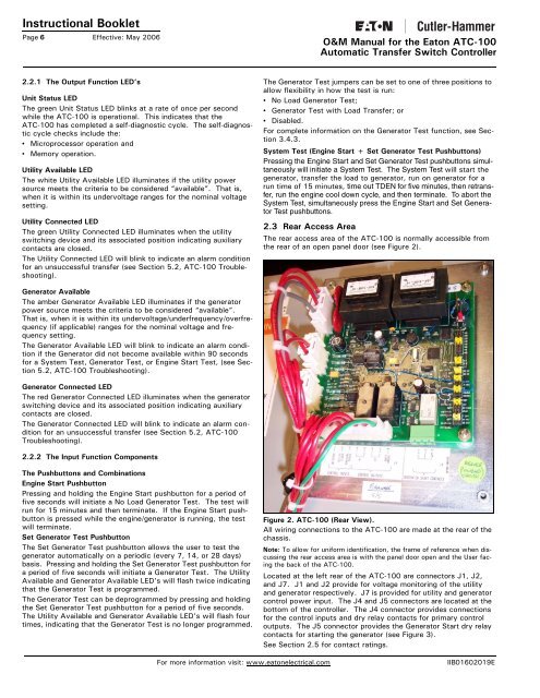
Figure 2. <strong>ATC</strong>-<strong>100</strong> (Rear View).<br />
All wiring connections to <strong>the</strong> <strong>ATC</strong>-<strong>100</strong> are made at <strong>the</strong> rear of <strong>the</strong><br />
chassis.<br />
Note: To allow <strong>for</strong> uni<strong>for</strong>m identification, <strong>the</strong> frame of reference when discussing<br />
<strong>the</strong> rear access area is with <strong>the</strong> panel door open and <strong>the</strong> User facing<br />
<strong>the</strong> back of <strong>the</strong> <strong>ATC</strong>-<strong>100</strong>.<br />
Located at <strong>the</strong> left rear of <strong>the</strong> <strong>ATC</strong>-<strong>100</strong> are connectors J1, J2,<br />
and J7. J1 and J2 provide <strong>for</strong> voltage monitoring of <strong>the</strong> utility<br />
and generator respectively. J7 is provided <strong>for</strong> utility and generator<br />
control power input. The J4 and J5 connectors are located at <strong>the</strong><br />
bottom of <strong>the</strong> controller. The J4 connector provides connections<br />
<strong>for</strong> <strong>the</strong> control inputs and dry relay contacts <strong>for</strong> primary control<br />
outputs. The J5 connector provides <strong>the</strong> Generator Start dry relay<br />
contacts <strong>for</strong> starting <strong>the</strong> generator (see Figure 3).<br />
See Section 2.5 <strong>for</strong> contact ratings.<br />
For more in<strong>for</strong>mation visit: www.eatonelectrical.com<br />
IIB01602019E