Electrowetting-Based Microfluidic Devices: Design Issues
Electrowetting-Based Microfluidic Devices: Design Issues
Electrowetting-Based Microfluidic Devices: Design Issues

You also want an ePaper? Increase the reach of your titles
YUMPU automatically turns print PDFs into web optimized ePapers that Google loves.
ELECTROWETTING-BASED MICROFLUIDIC DEVICES: DESIGN ISSUES<br />
Chao-Yi Chen, Eve F. Fabrizio, Ali Nadim, James D. Sterling<br />
Keck Graduate Institute of Applied Life Sciences<br />
Claremont, CA<br />
INTRODUCTION<br />
Although Lippmann first explored the phenomenon in 1875,<br />
electrocapillarity has only recently generated substantial interest in the<br />
context of its application to electrowetting [1,2]. <strong>Electrowetting</strong>-based<br />
droplet systems have been proposed for biological sample actuation<br />
and manipulation [2]. Recent advances utilizing a thin dielectric layer<br />
between an electrode and a liquid electrolyte are referred to as<br />
<strong>Electrowetting</strong> on Dielectric (EWOD) methods which demonstrate<br />
more stable and reproducible electrical characteristics than direct<br />
electrolyte/electrode contact systems [3,4]. The principle of operation<br />
is shown Figure 1 in which a liquid droplet is sandwiched between two<br />
hydrophobicly-coated dielectric glass plates with embedded<br />
electrodes. The droplet is made to electrowet the surface preferentially<br />
at one end by applying an electric potential across the ground electrode<br />
and the control electrode at that end. The resulting hydrodynamic<br />
pressure gradient inside the droplet forces the droplet towards the<br />
more wetting end until the entire drop covers the energized control<br />
electrode.<br />
Hydrophobic layer<br />
Hydrophobic<br />
dielectric layer<br />
Bottom glass plate<br />
Ground electrode<br />
Top glass plate<br />
Control electrodes<br />
Figure 1. <strong>Electrowetting</strong>-based actuation of a droplet<br />
sandwiched between two plates.<br />
Voltages on the order of ~100V have typically been required for<br />
the chosen dielectric materials and thicknesses. Droplet motion under<br />
these voltages has often shown hysteresis effects due to surface<br />
chemical modifications that occur at the higher field strengths. Moon,<br />
et al. [5] have successfully manipulated droplets with voltages as low<br />
as 15 V DC by reducing the thickness of the dielectric layer, increasing<br />
the permittivity of the dielectric material, and treating the dielectric<br />
surface to reduce the hysteresis effect [5]. There has been little focus,<br />
however, on reducing the viscous drag forces at the fluid-solid<br />
interface because grounding of the droplet has been through the upper<br />
electrode. In this work, we describe designs that reduce the viscous<br />
drag forces significantly by removing the top glass plate. These<br />
designs utilize either (a) alternating electrode potentials with a floating<br />
droplet potential or (b) ground electrode wires or small electrodes that<br />
are embedded into the bottom plate.<br />
DESIGN CHARACTERISTICS<br />
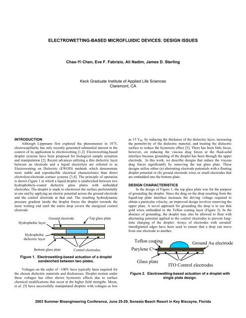
In the design of Figure 1, the top glass plate was for the purpose<br />
of grounding the droplet. Since the drag on the drop resulting from the<br />
liquid-top plate interface increases the driving voltage required to<br />
obtain a particular velocity, an improved design involves removing the<br />
upper plate. A novel approach for grounding the drop is to use thin<br />
gold wires embedded in the Teflon coating layer (Figure 2). In the<br />
absence of grounding, the droplet may also be allowed to float with<br />
alternating potential applied to the control electrodes to prevent longtime<br />
charging of the droplet. Arrays of electrodes with serrated/<br />
interdigitated edges have been used to ensure that a drop can move<br />
from one electrode to another.<br />
Teflon coating<br />
Parylene C<br />
Glass plate<br />
Ground Au electrode<br />
ITO Control electrodes<br />
Figure 2. <strong>Electrowetting</strong>-based actuation of a droplet with<br />
single plate design.<br />
2003 Summer Bioengineering Conference, June 25-29, Sonesta Beach Resort in Key Biscayne, Florida
Our designs begin with a 1200 Å indium-tin-oxide (ITO) precoated<br />
glass substrate from Delta Technologies to ensure optical<br />
transparency required for many fluorescence-based bioassays. The<br />
ITO is patterned to form the control electrodes using wet-etch microfabrication.<br />
Once electrically isolated electrodes have been formed,<br />
Parylene C or silicon dioxide is deposited as the insulating dielectric<br />
layer. For the grounding wires, gold is deposited in a 500 Å thick and<br />
50 µm wide band using a standard lift-off technique. The dielectric<br />
and ground wires are then covered by a ~300 Å layer of Teflon AF<br />
1611. The Teflon coating is thin enough that it provides only the<br />
requisite hydrophobicity of the surface but does not insulate the<br />
droplet from the ground gold electrode. The droplet is thus grounded<br />
through this gold wire without using the top plate.<br />
Experiments are performed using a Keithley 2400 source meter as<br />
the voltage source and a 40–channel Keithley 2700 to independently<br />
control the electrode potentials.<br />
ESTIMATES OF DROPLET VELOCITY<br />
In an effort to characterize the motion of droplets in<br />
electrowetting, consider a liquid droplet of volume V sandwiched<br />
between two plates with a channel depth of h shown in Figure 3a.<br />
Taking the contact angle for the left half of the droplet to be θ L and<br />
that of the right half to be θ R , we estimate the droplet speed U d by<br />
balancing the surface tension and the viscous wall-shear forces<br />
(neglecting any contact line friction or other motion-resisting forces):<br />
F<br />
F<br />
viscous<br />
surf<br />
2 12 µ U<br />
= 2τ wπ<br />
a =<br />
2<br />
h<br />
d<br />
V<br />
= 2aγ<br />
LV<br />
(cos θ<br />
R<br />
− cos θ<br />
L<br />
)<br />
where µ is the viscosity and γ LV is the surface tension of the liquidair<br />
interface and V is the volume of the droplet. The shear stress at the<br />
surfaces is taken to be 6µU d /h based on a plane Poiseuille flow. The<br />
droplet speed U d is obtained by equating the above two equations:<br />
γ<br />
LV<br />
h<br />
U<br />
d<br />
= (cos θ<br />
R<br />
− cos θ<br />
L<br />
)<br />
6πµ<br />
a<br />
stress as 5µU s /2H (based on the peak velocity located near 2/5 of<br />
droplet height that has been observed in some numerical simulations)<br />
we estimate the droplet velocity U s by the following:<br />
giving<br />
U<br />
U<br />
s<br />
s<br />
4 H γ<br />
LV<br />
=<br />
5πµ<br />
r<br />
U<br />
d<br />
24 Ha<br />
=<br />
5rh<br />
(cos θ<br />
R<br />
− cos θ )<br />
For contact angles near perpendicular, H ~ r and for fixed<br />
volume, V, and two-plate spacing, h, and equivalent electrowetting<br />
properties, we can expect an increase in droplet speed by utilizing a<br />
single-plate design that is approximately given by<br />
U<br />
s<br />
U<br />
d<br />
=<br />
24<br />
5<br />
V<br />
π h<br />
Clearly, a small plate spacing, h, results in large surface to volume<br />
ratios and high viscous drag so that large increases in droplet speed<br />
can be achieved by utilizing a single plate design.<br />
CONCLUSIONS<br />
A number of design issues associated with electrowetting<br />
microfluidic devices for liquid droplet actuation have been described.<br />
There are three major advantages in the use of single-plate<br />
electrowetting microfluidic designs. First, the manufacturing process<br />
can be simplified because steps required for maintaining uniform gap<br />
spacing can be eliminated. Secondly, the sample injection process<br />
would be much easier and the system can be readily integrated with<br />
existing microarray, liquid-handling and other laboratory automation<br />
systems. Thirdly, viscous drag can be reduced significantly resulting in<br />
increased droplet speed or reduced voltage requirements. These<br />
benefits indicate that a single-plate design approach has great potential<br />
for biological sample preparation and for integration with existing<br />
microarray spotting systems and other automated laboratory<br />
equipment.<br />
3<br />
L<br />
h<br />
Θ L<br />
a<br />
Θ R<br />
Θ L<br />
Η<br />
Θ R<br />
ACKNOWLEDGEMENTS<br />
This work was supported by the W. M. Keck Foundation and<br />
NIH K25 Award (Sterling). The authors would like to thank these two<br />
organizations for their financial support.<br />
3(a)<br />
3(b)<br />
Figure 3. Relevant dimensions and angles of electrowetting<br />
designs. (a) A liquid droplet sandwiched between two<br />
plates. (b) A liquid droplet sitting on top of a single-plate<br />
chip.<br />
The fastest velocity reported in the literature is ~24 cm/sec using<br />
optimized alternating electrode potentials (f~6-10kHz) with<br />
parameters of h=120µm and a~0.7mm[6]. According to the above<br />
equation, this velocity would require θ R =69° if θ L =90°, values which<br />
are indeed in the range of contact angle changes that are used in<br />
electrowetting devices.<br />
Figure 3b shows a liquid droplet, with volume V, sitting on the<br />
single-plate chip. By the same argument but using the estimated shear<br />
2r<br />
REFERENCES<br />
1. Lippmann, G., 1875, “Relation entre les phenomenes electriques<br />
et capillaires,” Ann. Chim. Phys., vol. 5, p.494.<br />
2. Quilliet, C. and Berge, B., “<strong>Electrowetting</strong>: a recent outbreak,”<br />
Current Opinion in Colloid & Interface Science, vol. 6, p.34.<br />
3. Vallet, M., Berge, B., Vovelle, L., 1996, “<strong>Electrowetting</strong> of<br />
water and aqueous solutions on poly(ethylene terephthalate)<br />
insulating films,” Polymer, vol. 37, p.2465.<br />
4. Pollack, M., Fair, R., Shenderov, A., 2000, “<strong>Electrowetting</strong>based<br />
actuation of liquid droplets for microfluidic<br />
applications,” Appl. Phys. Lett., vol.77, p.1725.<br />
5. Moon, H., Cho, S., Garrell, R., Kim, C., 2002, “Low voltage<br />
electrowetting-on-dielectric,” J. Appl. Phys, vol. 92, p.4080.<br />
6. Cho, S.K., Fan, S.-K., Moon, H., and Kim, C.-J., 2002,<br />
“Towards Digital <strong>Microfluidic</strong> Circuits,” IEEE Conf.<br />
MEMS, Las Vegas, NV, p. 32-52.<br />
2003 Summer Bioengineering Conference, June 25-29, Sonesta Beach Resort in Key Biscayne, Florida