EQUIPOTENTIAL SURFACES COMPUTER LAB ACTIVITY ... - PhET
EQUIPOTENTIAL SURFACES COMPUTER LAB ACTIVITY ... - PhET
EQUIPOTENTIAL SURFACES COMPUTER LAB ACTIVITY ... - PhET

You also want an ePaper? Increase the reach of your titles
YUMPU automatically turns print PDFs into web optimized ePapers that Google loves.
<strong>EQUIPOTENTIAL</strong> <strong>SURFACES</strong> <strong>COMPUTER</strong> <strong>LAB</strong> <strong>ACTIVITY</strong><br />
Name:__________________________<br />
Remember that an equipotential surface is the set of all points around a group of<br />
charges that are at the same potential. Hese surfaces allow us to calculate the<br />
amount of work needed to move a charge from one spot to another. The amount<br />
of work needed to move a charge q through a potential difference ∆V is given by:<br />
W=q∆V<br />
The purpose of today’s activity is to make you familiar with the shape and<br />
appearance of these equipotential surfaces and their replationship to the electric<br />
field.<br />
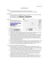
1. After you have logged on to the computer, go to the resources page of<br />
the website and click the button labeled “Potential Surfaces and<br />
Electric Fields Activity” and save it to the desktop. Open the program<br />
from the desktop and maximize the screen. You will see an area for<br />
grabbing charges that can be placed in the area on the screen, a green<br />
box that allows you to change certain aspects of the area, and a<br />
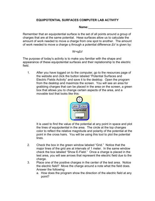
movable tool that looks like this:<br />
It is used to find the value of the potential at any point in space and plot<br />
the lines of equipotential in the area. The circle at the top changes<br />
color to reflect the relative magnitude and polarity of the potential at the<br />
point in the cross hairs. You will be using this tool to plot the potential<br />
lines.<br />
2. Check the box in the green window labeled “Grid.” Notice that the<br />
major lines of the grid are at intervals of 1 meter. In the same window<br />
check the box labeled “Show E-Field.” Once a charge is placed in the<br />
test area, you will see arrows that represent the electric field due to the<br />
charge.<br />
3. Place one of the positive charges in the center of the test area. Notice<br />
the electric field Move the charge around a note what the field does.<br />
Answer the following:<br />
a. How does the program show the direction of the electric field at any<br />
point
. How does the program show the magnitude of the electric field at<br />
any point<br />
c. Where is the electric field strongest<br />
d. In the diagram below, draw the electric field of a positive point<br />
charge:<br />
4. Move the equipotential tool around the test area and note the color<br />
change of the circle.<br />
a. How is it related to the voltage measured in the field<br />
b. Where is the voltage the highest<br />
Use the tool to plot equipotential lines at 1m intervals from the charge.<br />
Fill in the table below:<br />
Distance (m) Voltage (V)<br />
1<br />
2<br />
3<br />
4<br />
5<br />
6<br />
Create a graph of the data and attach the graph to your lab. Does the<br />
voltage due to a point charge vary directly or inversely with distance<br />
from the charge
In the diagram from number three, draw in the equipotential lines<br />
around your charge.<br />
c. How is the electric field oriented relative to the equipotential lines<br />
5. Clear the test area. Place a negative charge in the test area. On the<br />
diagram below, draw in the electric field lines and equipotential lines<br />
for a negative charge:<br />
a. How are the field lines oriented relative to the equipotential lines<br />
6. Clear the test area. Place two positive charges a distance of 3 m apart<br />
in the test area. Use the diagram below to draw in the field and<br />
equipotential lines:
7. Repeat for two negative charges:
8. Repeat for a positive and a negative charge. This configuration is what<br />
is called a “dipole.”<br />
9. Repeat for a double line of oppositely polarized charges. This will take<br />
a little time to set up:
10. What does the electric field of the previous configuration resemble<br />
11. For all the configurations, the following should be true statements.<br />
Circle the boldfaced choice that will make each one true.<br />
The electric field points in the direction of increasing / decreasing voltage.<br />
A positive charge released in an electric field will spontaneously move with / against field lines.<br />
A positive charge released in an electric field will spontaneously move from regions of high / low<br />
potential to regions of high / low potential.<br />
A negative charge released in an electric field will spontaneously move with / against field lines.<br />
A negative charge released in an electric field will spontaneously move from regions of high / low<br />
potential to regions of high / low potential.