A Dual Band Microstrip Dipole Antenna For Wideband Application
A Dual Band Microstrip Dipole Antenna For Wideband Application
A Dual Band Microstrip Dipole Antenna For Wideband Application

Create successful ePaper yourself
Turn your PDF publications into a flip-book with our unique Google optimized e-Paper software.
ISSN 2249-6343<br />
International Journal of Computer Technology and Electronics Engineering (IJCTEE)<br />
Volume 2, Issue 6, December 2012<br />
A <strong>Dual</strong> <strong>Band</strong> <strong>Microstrip</strong> <strong>Dipole</strong> <strong>Antenna</strong><br />
<strong>For</strong> <strong>Wideband</strong> <strong>Application</strong><br />
Nitali Garg, Zarreen Aijaz<br />
Abstract - In this paper, the design of dual band microstrip<br />
dipole antenna is incorporated with two different dipole arms. A<br />
bandwidth of 22% and 40% around a center frequency of 2.4<br />
GHz is obtained. It is a dual band microstrip dipole antenna<br />
with minimum return loss of -36db. This antenna is designed on<br />
a FR4 substrate with a dielectric constant 4.4 on double sided<br />
PCB. This antenna is low cost, easy to design and light weighted;<br />
easy to convince for mass production.<br />
Index Terms— microstrip antenna, printed dipole, resonant<br />
antenna, Frequency band.<br />
I. INTRODUCTION<br />
In modern wireless communication system; the design of<br />
an antenna is required, that will operate in a wide band or<br />
multiband mode, which also cover several different services.<br />
A microstrip dipole is a good and easy approach, for a system<br />
where an Omni directional pattern is required, as for example<br />
in a portable device. <strong>Microstrip</strong> or printed dipole antenna<br />
have been of the most popular type of antenna in the last<br />
twenty years. In this paper, a tapered microstrip dipole<br />
antenna is designed at the frequency of 2.4 GHz is proposed.<br />
Then a wide band rectangular microstrip dipole antenna is<br />
designed around the frequency of 2.4 GHz is adduced. Both<br />
antennas are designed with additional arm and shorting plate.<br />
The dimensions of additional arm and shorting plate are<br />
designed in terms of guided wavelength. The bandwidth of<br />
microstrip dipole antenna is very high as compared to the<br />
microstrip patch antenna. <strong>Microstrip</strong> antennas are very<br />
popular because of its low profile, low weight and low<br />
production cost. If the antenna is to be implemented on the<br />
same PCB as the circuitry, practically no additional costs<br />
arise, that’s why microstrip antennas are very popular.<br />
II. ANTENNA DESIGN AND ANALYSIS<br />
In this paper, proposed half wave microstrip dipole antennas<br />
are printed on a 1.6 mm thickness double sided FR4 substrate<br />
with dielectric constant of 4.4 at operating frequency of<br />
2.4GHz.<br />
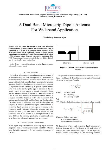
(Top view)<br />
(bottom view)<br />
Figure 1: Geometry of tapered microstrip dipole<br />
antenna<br />
The geometries of microstrip dipole antennas are shown in<br />
figure 1 and figure 2. The effective wavelength of antenna is<br />
calculated by using the formula<br />
Where<br />
And<br />
Where<br />
λg=Wavelength<br />
F= Frequency<br />
C= Velocity of light<br />
=Effective dielectric constant of a microstrip line which is<br />
=Dielectric constant<br />
d = Substrate thickness<br />
w= Width of microstrip line<br />
All dimensions of proposed microstrip dipole antennas are<br />
designed in terms of λg. The length, width and height of<br />
substrate are taken respectively 3λg/4, λg/4 and λg/4/10.5.<br />
Adduced antenna is excited by a 50 Ohm microstrip feed line.<br />
18
ISSN 2249-6343<br />
International Journal of Computer Technology and Electronics Engineering (IJCTEE)<br />
Volume 2, Issue 6, December 2012<br />
(top view)<br />
(bottom view)<br />
Figure 2: Geometry of ractangular microstrip dipole<br />
antenna<br />
III. SIMULATION AND RESULT<br />
Proposed microstrip dipole antenna has been simulated with<br />
HFSS 13.0 from ANSYS software. The simulation results for<br />
both dipole antennas are discussed in term of bandwidth<br />
response and input return loss.<br />
Figure 4: Return loss for microstrip dipole with tapered<br />
arm.<br />
(A) TAPERED MICROSTRIP DIPOLE WITH SHORTING PLATE<br />
Figure 3 shows the side view of microstrip dipole antenna<br />
with tapered arm. Proposed microstrip dipole antennas are<br />
designed at a frequency of 2.4 GHz. In this figure, the ground<br />
plane considered to be half of the substrate. The length and<br />
width of ground plane is given by 1.5λg/4 and λg/4 respectively.<br />
Figure 5: 3D polar plot of microstrip dipole<br />
antenna<br />
Figure 3: <strong>Microstrip</strong> dipole antenna with tapered arm<br />
(side view).<br />
Figure 4 represent the simulated return loss of microstrip<br />
dipole antenna. The simulated bandwidth of microstrip dipole<br />
antenna is 575.8 MHz and 60.6 MHz.<br />
The maximum bandwidth of microstrip dipole with tapered<br />
arm shorting plate is 22.12% is obtained.<br />
Figure 5 and Figure 6 shows the 3D polar plot and radiation<br />
pattern of microstrip dipole antenna respectively.<br />
References of figure and results are taken from the HFSS 13.0<br />
software.<br />
Figure 6: 3D radiation pattern of microstrip dipole<br />
antenna.<br />
19
ISSN 2249-6343<br />
International Journal of Computer Technology and Electronics Engineering (IJCTEE)<br />
Volume 2, Issue 6, December 2012<br />
(B) RECTANGULAR DIPOLE WITH SHORTING PLANE<br />
Instead of tapered arm; rectangular arm is used in<br />
microstrip dipole antenna with shorting plate, which gives<br />
wider bandwidth. The gap between dipole arms remains same<br />
as well the ground Plane.<br />
The side view of microstrip dipole with rectangular arm is<br />
shown in Figure 7.<br />
Figure 9: 3D polar plot for microstrip dipole antenna<br />
with rectangular arm<br />
Figure 7: <strong>Microstrip</strong> dipole antenna with rectangular<br />
arm<br />
The simulated return loss of microstrip dipole antenna is<br />
presented in figure 8 with dual band.<br />
In simulation result a dual band of 1.21 GHz and 60 MHz is<br />
obtained. The 3D polar plot of proposed dual band microstrip<br />
dipole antenna is also shown in figure 9.<br />
ACKNOWLEDGMENT<br />
Nitali garg thanks to Dr. Zarreen Aijaz who gave me the<br />
possibility to complete this paper.<br />
REFERENCES<br />
[1] Floc'h, J.M.; Kokar, .Wide band printed dipole for Wi-Fi and WiMax<br />
applications ”<strong>Antenna</strong>s and Propagation Conference (LAPC), 2011<br />
Loughborough , Page(s): 1 – 4.<br />
[2] Jamaluddin, M.H.; Rahim, M.K. A.; Aziz, M. Z. A. Abd.; Asrokin, A.”<br />
<strong>Microstrip</strong> dipole antenna for WLAN application” IEEE conference<br />
publications, Publication Year: 2005, Page(s): 30 – 33.<br />
[3] Qing-Qiang He; Bing-Zhong Wang; Jun He<br />
“<strong>Wideband</strong> and <strong>Dual</strong>-<strong>Band</strong> Design of a Printed <strong>Dipole</strong> <strong>Antenna</strong>”<br />
<strong>Antenna</strong>s and Wireless Propagation Letters, IEEE Vol.7,2008 ,<br />
Page(s): 1 – 4.<br />
[4] Jwo-Shiun Sun; Guan-Yu Chen; Sen-Yi Huang; Chuang-Jen Huang;<br />
Kuo-Liang Wu; Chen, Y.D.; Cheng-Hung Lin “The Omni-directional<br />
<strong>Dipole</strong> <strong>Antenna</strong> Structure and Design” <strong>Antenna</strong>s, Propagation & EM<br />
Theory, 2006. Page(s): 1 – 4.<br />
[5] Tsai,C.J.;Lin,C.S.;Chen,W.C.”A dual-band microstrip-matched print<br />
ed antenna for WLAN/WiMax applications” Microwave Conference<br />
Proceedings (APMC), 2011,Page(s): 1726 – 1729<br />
[6] Floc'h, J.M.” Wide band printed dipole design” Mediterranean<br />
Microwave Symposium (MMS), 2011, Page(s): 57 – 60.<br />
[7] Ruina Wang; Quanyuan Feng “Design of a novel wideband microstrip<br />
antenna” Electrical and Control Engineering (ICECE), 2011,Page(s):<br />
2972 – 2974.<br />
Figure 8: Return loss for microstrip dipole antenna with<br />
rectangular arm.<br />
IV. CONCLUSION<br />
The performance of dual band microstrip dipole antenna<br />
with two different arms on same ground plane has been<br />
analyzed at a frequency of 2.4 GHz for wideband application<br />
has been simulated in this paper. The shorting plate between<br />
the ground plane and dipole arm improve the bandwidth of<br />
antenna as well as provide double band. By using this shorting<br />
plane technique 40% bandwidth with minimum return loss of<br />
-36 db is obtained.<br />
Nitali garg received her Bachelor of Engineering (Electronics<br />
and communication) from Rajiv Gandhi Proudyogiki<br />
Vishwavidyalaya, Bhopal in 2009 and currently she is pursuing<br />
M-tech (digital communication) from the same institute. Her<br />
research fields focus on microstrip antenna analysis and<br />
designing<br />
Dr. Zarreen Aijaz received her Bachelor of Engineering<br />
(Electronics and telecommunication) from North<br />
Maharashtra University Jalgaon (M.S.) India in 1997,<br />
M.Tech (Microwave and millimeter waves) from Maulana<br />
Azad National Institute of Technology, Bhopal, India and<br />
doctorate (Design and development of double slot coupled<br />
microstrip antenna) from Maulana Azad National Institute of Technology,<br />
Bhopal, India. Her research fields focus on various antenna analysis, design<br />
and measurement, high-frequency electromagnetic simulators. She has<br />
authored several papers in national and international Journals and<br />
conferences<br />
20