Pacific HF Acid Valves Catalog - Petro-Valve
Pacific HF Acid Valves Catalog - Petro-Valve
Pacific HF Acid Valves Catalog - Petro-Valve

Create successful ePaper yourself
Turn your PDF publications into a flip-book with our unique Google optimized e-Paper software.
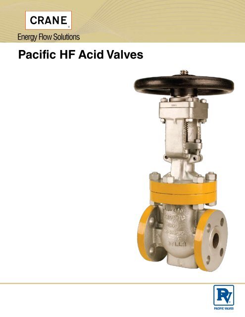
<strong>Pacific</strong> <strong>HF</strong> <strong>Acid</strong> <strong><strong>Valve</strong>s</strong><br />
PACIFIC VALVES
<strong>HF</strong> ACID<br />
API 602 and API 600<br />
By Subject<br />
UOP and Phillips <strong>Valve</strong> Index..................................................................................4<br />
Product/Market Overview........................................................................................5<br />
API 602 Compact Gate <strong>Valve</strong> Features...................................................................6<br />
API 600 Bolted Bonnet Gate <strong>Valve</strong> Features...........................................................7<br />
High Integrity Shutoff Gate <strong><strong>Valve</strong>s</strong>...........................................................................8<br />
API 602 Compact Globe <strong>Valve</strong> Features.................................................................9<br />
API 600 Bolted Bonnet Globe <strong>Valve</strong> Features....................................................... 10<br />
API 602 and API 600 Check <strong>Valve</strong> Features......................................................... 11<br />
Grease Injectors.................................................................................................... 12<br />
Service Recommendations................................................................................... 13<br />
UOP <strong>Valve</strong> Product Line...................................................................................14-37<br />
Phillips <strong>Valve</strong> Product Line...............................................................................38-50<br />
Figure Number System..........................................................................................51<br />
3
<strong>HF</strong> <strong>Acid</strong> <strong><strong>Valve</strong>s</strong><br />
UOP and Phillips <strong>Valve</strong> Index<br />
UOP Index<br />
Gate <strong><strong>Valve</strong>s</strong><br />
Class 800..................................Fig. No. 3656-<strong>HF</strong>8 ........................................ 14<br />
Class 800..................................Fig. No. 3656-<strong>HF</strong>8 (-M35-1).......................... 15<br />
Class 300..................................Fig. No. 357GR-<strong>HF</strong>8 (-M35-1)....................... 16<br />
Class 600..................................Fig. No. 3654GR-<strong>HF</strong>8 (-M35-1)..................... 17<br />
Class 800..................................Fig. No. 3656G-<strong>HF</strong>8T.................................... 18<br />
Class 150..................................Fig. No. 150-<strong>HF</strong>8........................................... 19<br />
Class 300..................................Fig. No. 350-<strong>HF</strong>8........................................... 20<br />
Class 300..................................Fig. No. 350GR-<strong>HF</strong>8T................................... 21<br />
Class 300..................................Fig. No. 350GR-<strong>HF</strong>8-BTT.............................. 22<br />
Class 300..................................Fig. No. 350L(2)-<strong>HF</strong>8-BTT............................. 22<br />
Globe <strong><strong>Valve</strong>s</strong><br />
Class 300..................................Fig. No. 3367G-<strong>HF</strong>8T.................................... 23<br />
Class 600..................................Fig. No. 665-<strong>HF</strong>8 (-M35-1)............................ 24<br />
Class 600..................................Fig. No. 3667-<strong>HF</strong>8 (-M35-1)........................... 25<br />
Class 800..................................Fig. No. 667-<strong>HF</strong>8........................................... 26<br />
Class 800..................................Fig. No. 3669-<strong>HF</strong>8......................................... 27<br />
Class 800..................................Fig. No. 3669G-<strong>HF</strong>8T.................................... 28<br />
Class 150..................................Fig. No. 160-<strong>HF</strong>8........................................... 29<br />
Class 300..................................Fig. No. 360-<strong>HF</strong>8........................................... 30<br />
Class 300..................................Fig. No. 360GR-<strong>HF</strong>8T................................... 31<br />
Class 300..................................Fig. No. 366-<strong>HF</strong>8 (-M35-1)............................ 32<br />
Check <strong><strong>Valve</strong>s</strong><br />
Class 800..................................Fig. No. 3682-<strong>HF</strong>8......................................... 33<br />
Class 600..................................Fig. No. 3680-<strong>HF</strong>8 (-M35-1).......................... 34<br />
Class 150..................................Fig. No. 180-<strong>HF</strong>8........................................... 35<br />
Class 300..................................Fig. No. 380-<strong>HF</strong>8........................................... 36<br />
Class 300..................................Fig. No. 380R-<strong>HF</strong>8........................................ 37<br />
Phillips Index<br />
Gate <strong><strong>Valve</strong>s</strong><br />
Class 300..................................Fig. No. 3354P-<strong>HF</strong>8 (-M35-1)........................ 38<br />
Class 600 .................................Fig. No. 3654P-<strong>HF</strong>8 (-M35-1)........................ 39<br />
Class 800..................................Fig. No. 3655P-<strong>HF</strong>8 (-M35-1)........................ 40<br />
Class 800..................................Fig. No. 3655P-<strong>HF</strong>8 ...................................... 41<br />
Class 300..................................Fig. No. 350P-<strong>HF</strong>8 (-M35-1).......................... 42<br />
Class 300..................................Fig. No. 350P-<strong>HF</strong>8-BTT (-M35-1).................. 43<br />
Class 300..................................Fig. No. 350L(2)-<strong>HF</strong>8-BTT (-M35-1).............. 43<br />
Globe <strong><strong>Valve</strong>s</strong><br />
Class 300..................................Fig. No. 3367P-<strong>HF</strong>8....................................... 44<br />
Class 600..................................Fig. No. 3667P-<strong>HF</strong>8....................................... 45<br />
Class 800..................................Fig. No. 3668P-<strong>HF</strong>8 (-M35-1)........................ 46<br />
Class 800..................................Fig. No. 3668P-<strong>HF</strong>8T (-M35-1)...................... 47<br />
Class 300..................................Fig. No. 360P-<strong>HF</strong>8......................................... 48<br />
Check <strong><strong>Valve</strong>s</strong><br />
Class 800..................................Fig. No. 3681P-<strong>HF</strong>8 (-M35-1)........................ 49<br />
Class 300..................................Fig. No. 380P-<strong>HF</strong>8......................................... 50<br />
4
<strong>HF</strong> <strong>Acid</strong> <strong><strong>Valve</strong>s</strong><br />
Product/Market Overview<br />
The Leading Source for <strong>HF</strong> <strong>Acid</strong> <strong><strong>Valve</strong>s</strong><br />
and Related Technology<br />
Experience<br />
<strong>Pacific</strong> <strong><strong>Valve</strong>s</strong> has been manufacturing valves for this very difficult<br />
service for over 50 years. We are considered the pioneers of this<br />
type of valving. In fact, we are the only valve manufacturer originally<br />
approved by all the major hydro-fluoric acid licensors (U.O.P., Phillips<br />
<strong>Petro</strong>leum and Chevron) in all sizes and pressure ranges.<br />
Primary Monel ® parts are color coded to assure proper material<br />
identification. We do not stop here. Before any Monel ® part is assembled<br />
into a hydrofluoric acid valve it is acid tested to assure that<br />
it is Monel ® . Another important aspect in the manufacture of these<br />
valves is the clearances at the critical metal interfaces (wedge/body<br />
guides, stem/back seat bushing, etc.). Hydrofluoric acid will react<br />
with carbon steel and Monel ® producing a fluoride buildup on the<br />
metal surfaces which can render the valve in-operable. These clearances,<br />
developed over years of manufacturing experience, testing<br />
and research, must be precisely controlled to allow for this buildup.<br />
Our experience has enabled us to consistently produce valves that<br />
give the best performance for this stringent service.<br />
Certified Quality<br />
All of our pressure tests and material checks are witnessed by an<br />
inspector who signs off on their accuracy. A laminated card is then<br />
attached to the valve with each test and material check indicated,<br />
as certification to our customer that these procedures have been<br />
followed. Every valve comes with this certification attached to it.<br />
Every <strong>Valve</strong> is Tested<br />
We test 100% of our hydrofluoric acid valves with kerosene. Our<br />
experience indicates that kerosene is the most ideal test media for<br />
the following reasons:<br />
• It prevents water entrapment; water entrapped in the valve<br />
internals will accelerate corrosion.<br />
• It assures casting quality; kerosene is less viscous than<br />
water, thus will locate a casting defect more readily than<br />
other test fluids.<br />
• It provides seat test reliability; again, the viscosity of<br />
kerosene provides a more reliable seat leakage indication.<br />
We test our hydrofluoric acid valves at extended time periods to<br />
further assure the quality of the valve performance. In addition, we<br />
test our <strong>HF</strong> <strong>Acid</strong> valves with Helium at 300 PSI to insure the casting<br />
integrity.<br />
Large In-house Inventory<br />
Recognizing the need to continue our service beyond initial installation,<br />
we have committed to the refiners and licensors that an inventory<br />
of hydrofluoric acid valves will be maintained at <strong>Pacific</strong> <strong><strong>Valve</strong>s</strong>. We<br />
routinely carry valves in inventory that meet the licensor’s specification<br />
for quick delivery to your plant.<br />
When you purchase <strong>Pacific</strong> hydrofluoric acid valves, you are really getting:<br />
• Reliability<br />
• Quality<br />
• Peace of Mind<br />
knowing that you have bought the most reliable product for this<br />
very difficult service.<br />
Monel ® is a registered trademark of Special Metals Corporation.<br />
5
<strong>HF</strong> <strong>Acid</strong> Gate <strong><strong>Valve</strong>s</strong><br />
API 602 Compact Gate Features<br />
Rising Stem – easily visible<br />
open-close indication.<br />
Handwheel – large handwheels<br />
for easy operation.<br />
Grease Fittings – yoke sleeves<br />
equipped with grease fittings to minimize<br />
wear and operating torque.<br />
Yoke Sleeves – furnished in 416<br />
stainless steel or aluminum-bronze.<br />
Swing Bolts – facilitate easier<br />
maintenance and packing replacement.<br />
Stuffing Box – optional lantern<br />
rings and grease injectors are available.<br />
Gland – two-piece gland/gland<br />
flange is self-aligning to eliminate<br />
stem damage from cocked gland.<br />
Stem – precision machined stem has a<br />
backseat design.<br />
Bonnet Joint – encapsulated<br />
gasket design.<br />
Body – full ported, heavy duty body<br />
with API 602 wall thickness for<br />
maximum service life.<br />
Wedge – fully guided wedge precision<br />
fitted to body seats for maximum shutoff.<br />
Seat Rings – separate heavy duty,<br />
full ported rings for easy maintenance.<br />
End Connections – choice of flanged,<br />
threaded or socket weld ends.<br />
OPTIONS<br />
GREASE INJECTOR AND<br />
LANTERN RING<br />
SOFT SEATED “T” TRIM SEAT RING<br />
All gate valves are available with optional PTFE seat rings. The molded<br />
PTFE ring is bonded into a seat ring groove in the face for maximum<br />
service life. This design is excellent for lower temperature service where<br />
tight shutoff is required.<br />
END END END<br />
END CONNECTIONS<br />
CONNECTIONS<br />
Socket Socket Weld Socket<br />
Weld Weld Flanged<br />
Weld<br />
Flanged Threaded<br />
Flanged Threaded Threaded<br />
6
<strong>HF</strong> <strong>Acid</strong> Gate <strong><strong>Valve</strong>s</strong><br />
API 600 Bolted Bonnet Gate Features<br />
Rising Stem – easily visible<br />
open-close indication.<br />
Grease Fittings – yoke sleeves<br />
equipped with fittings to minimize<br />
wear and operating torque.<br />
Handwheel – large handwheels<br />
for easy operation. Also available<br />
with gearing, motor actuators<br />
or cylinder actuators for more<br />
difficult services.<br />
Yoke Sleeves – furnished in ductile<br />
Ni-resist or aluminum-bronze to<br />
reduce operating torque.<br />
Swing Bolts – facilitate easier<br />
maintenance and packing replacement.<br />
Stuffing Box – optional lantern<br />
rings and grease injectors are<br />
available.<br />
Backseat – machined bonnet stem<br />
bushing provides back-up stem seal.<br />
Bonnet Joint – joint design<br />
varies with ASME class rating.<br />
Gland – two-piece gland/gland<br />
flange is self-aligning to eliminate<br />
stem damage from cocked gland.<br />
Stem – all <strong>Pacific</strong> wedge gate valves<br />
are provided with upset forged T-head<br />
stems. By forging the T-head, the<br />
stem at the stem-wedge connection<br />
is stregthened. This design also<br />
allows the wedge to self-align,<br />
eliminating the possibility of a bent<br />
stem jamming the wedge.<br />
Body – full ported, heavy duty body<br />
with API 600 wall thickness for maximum<br />
service life. Provided with bosses<br />
for optional by-passes or drains.<br />
Seat Rings – separate heavy duty,<br />
full ported rings for easy maintenance.<br />
Wedge – heavy pattern, fully guided<br />
wedge precision fitted to body seats<br />
for maximum shutoff. Available in<br />
H.I.S. design.<br />
End Connections – flanged end options<br />
are raised face smooth finish or ring<br />
type joint.<br />
GREASE INJECTOR AND<br />
LANTERN RING<br />
OPTIONS<br />
HIGH INTEGRITY<br />
SHUTOFF WEDGE<br />
This fire safe design provides a zero<br />
leakage barrier on both upstream and<br />
downstream. Detail description is found<br />
on page 8.<br />
SOFT SEATED “T” TRIM<br />
SEAT RING<br />
All gate valves are available with optional<br />
PTFE seat rings. The molded PTFE ring<br />
is bonded into a seat ring groove in the<br />
face for maximum service life. This design<br />
is excellent for lower temperature service<br />
where tight shutoff is required.<br />
MONEL ® SLEEVED<br />
STUFFING BOX<br />
7
<strong>HF</strong> <strong>Acid</strong> <strong><strong>Valve</strong>s</strong><br />
API 600 High Integrity Shutoff Gate <strong>Valve</strong><br />
For services that require bubble tight shutoff specify <strong>Pacific</strong>’s High Integrity Shutoff gate valves. These fire-safe valves provide<br />
a bubble tight barrier on both upstream and down stream seats and eliminate possible product contamination or loss of fluids<br />
due to valve leakage.<br />
The HIS construction retains the proven reliability and low maintenance of <strong>Pacific</strong>’s standard API-600 gate valve. A resilient<br />
seal is locked into the wedge by a retainer plate. Special seat rings are installed to provide a wide seating surface for both the<br />
elastomer and metal wedge seating surfaces. A full range of trim and shell materials, end connections, piping and actuator<br />
options are available for corrosive services and temperatures up to 450°F.<br />
Solid Monel ® Wedge<br />
Monel ® Seat Ring<br />
PTFE Resilient<br />
Seal Ring<br />
K-Monel ® Cap Screws<br />
Monel ® Compression<br />
Plate<br />
8<br />
Heavy patterned,<br />
fully guided solid<br />
Monel ® wedge is<br />
precision fitted and<br />
hydrostatic tested<br />
before resilient seals<br />
are installed.<br />
Pressure-energized<br />
resilient seals<br />
available in PTFE<br />
(BTT) for maximum<br />
versatility.<br />
Mechanically<br />
retained, Monel ® seal<br />
plate allows fast,<br />
easy resilient seal<br />
replacement.<br />
Special extra width, Monel ®<br />
seat ring allows for wear<br />
without loss of seal.
<strong>HF</strong> <strong>Acid</strong> Globe <strong><strong>Valve</strong>s</strong><br />
API 602 Compact Globe <strong>Valve</strong> Features<br />
Handwheel – large handwheels<br />
for easy operation.<br />
Yoke Sleeves – furnished in 416.<br />
stainless steel or aluminum bronze to<br />
reduce operating torque.<br />
Stem – machined stem<br />
has a backseat design.<br />
Swing Bolts – facilitate easier<br />
maintenance and packing replacement.<br />
Stuffing Box – optional lantern<br />
rings and grease injectors are available.<br />
Gland – two-piece gland/gland<br />
flange is self-aligning to eliminate<br />
stem damage from cocked gland.<br />
Backseat – machined bonnet<br />
backseat provides back-up stem seal.<br />
Bonnet Joint – encapsulated<br />
bonnet gasket.<br />
Body – heavy duty body with<br />
API 602 wall thickness for maximum<br />
service life.<br />
Seat Ring – threaded into body for<br />
easy maintenance.<br />
End Connections – choice of flanged,<br />
socket weld or threaded ends<br />
for piping flexibility.<br />
OPTIONS<br />
GREASE INJECTOR AND<br />
LANTERN RING<br />
GREASE INJECTOR<br />
IN SEAT<br />
SOFT SEATED “T” TRIM<br />
All valves are available with optional soft<br />
seated PTFE trim. The molded PTFE ring<br />
is bonded into a groove in the disc face<br />
for maximum service life. This design is<br />
excellent for lower temperature service<br />
where tight shutoff is required.<br />
9
<strong>HF</strong> <strong>Acid</strong> Globe <strong><strong>Valve</strong>s</strong><br />
API 600 Bolted Bonnet Globe <strong>Valve</strong> Features<br />
Yoke Sleeves – furnished in ductile<br />
Ni-resist or aluminum-bronze to<br />
reduce operating torque.<br />
Swing Bolts – facilitate easier<br />
maintenance and packing replacement.<br />
Handwheel – large handwheels<br />
for easy operation. Also available<br />
with gearing, motor actuators<br />
or cylinder actuators for more<br />
difficult services.<br />
Stem – precision machined stem<br />
has forged T-Head for reliable<br />
stem/wedge connection.<br />
Gland – two-piece gland/gland<br />
flange is self-aligning to eliminate<br />
stem damage from cocked gland.<br />
Stuffing Box – optional lantern<br />
rings and grease injectors are available.<br />
Bonnet Joint – joint design varies<br />
with ASME class rating.<br />
Backseat – machined bonnet stem<br />
bushing provides back-up stem seal.<br />
Body – full ported, heavy duty body<br />
with API 600 wall thickness for maximum<br />
service life. Provided with bosses<br />
for optional drains.<br />
Seat Ring – heavy duty, full ported<br />
rings threaded into body for easy<br />
maintenance.<br />
End Connections – choice of raised<br />
face smooth finish or ring type joint<br />
for piping flexibility.<br />
GREASE INJECTOR AND<br />
LANTERN RING<br />
OPTIONS<br />
GREASE INJECTOR<br />
IN SEAT<br />
SOFT SEATED “T” TRIM<br />
All valves are available with optional soft<br />
seated PTFE trim. The molded PTFE ring<br />
is bonded into groove in the disc face for<br />
maximum service life. This design is excellent<br />
for lower temperature service where tight<br />
shutoff is required.<br />
10
<strong>HF</strong> <strong>Acid</strong> Check <strong><strong>Valve</strong>s</strong><br />
API 602 and 600 Check <strong>Valve</strong> Features<br />
API 602<br />
Bonnet Joint – encapsulated<br />
gasket design.<br />
Seat Ring – heavy duty, threaded.<br />
Disc – machined seating surface is mated to seat<br />
ring for positive shutoff.<br />
End Connections – choice of flanged,<br />
threaded or socket ends for piping flexibility.<br />
Body – heavy duty body with API 602<br />
wall thickness for maximum service life.<br />
API 600<br />
Pipe Plug – standard feature for Phillips<br />
spec. valves.<br />
Bonnet Joint – joint design varies<br />
with ASME class rating.<br />
Hinge Pin – precision machined solid<br />
pin for maximum strength and service life.<br />
Hinge – designed to withstand the shock<br />
load of quick closing to insure longer<br />
life and continued shut-off.<br />
Seat Ring – heavy duty, full ported<br />
seal welded into body.<br />
Disc Stop – provides positive stop in open<br />
position; positions disc to effectively function in<br />
either horizontal or vertical (flow-up) pipe runs.<br />
Anti-Rotation Lugs – lugs allow disc to seat<br />
freely and prevent disc spinning and wear.<br />
Disc – rugged disc is bolted and pinned to hinge;<br />
machined seating surface is mated to seat ring<br />
for positive shutoff.<br />
End Connections – choice of raised<br />
face smooth finish or ring type joint<br />
for piping flexibility.<br />
Body – full ported, heavy duty body with API 600<br />
wall thickness for maximum service life. Provided<br />
with bosses for optional drains.<br />
11
<strong>HF</strong> <strong>Acid</strong> <strong><strong>Valve</strong>s</strong><br />
Grease Injectors<br />
DOUBLE BALL GREASE INJECTOR<br />
<strong>Pacific</strong> <strong><strong>Valve</strong>s</strong>' unique injector has a double ball check protection<br />
against leakage and a positive shut-off internal valve. The injector<br />
button head must be unscrewed one half turn to open the internal<br />
valve before injecting grease. While unscrewing the injector button<br />
head, a second wrench must be used to assure that the injector body<br />
is not loosened from the main valve. After grease injection the head<br />
is then retightened to maintain positive shut-off.<br />
1 2 3 4 5 6 7 8<br />
PARTS LIST CARBON STEEL<br />
ITEM DESCRIPTION MATERIAL<br />
1 Ball Check 302 S.S.<br />
2 Spring Music Wire<br />
3 Head Housing ASTM A108 GR 1018<br />
4 Needle ASTM A108 GR 1018<br />
5 <strong>Valve</strong> Housing ASTM A108 GR 1018<br />
6 Ball Check Monel ®<br />
7 Ball Check Monel ®<br />
8 Pin ASTM A108 GR 1018<br />
PARTS LIST MONEL ®<br />
ITEM DESCRIPTION MATERIAL<br />
1 Ball Check Monel ®<br />
2 Spring Music Wire<br />
3 Head Housing Monel ®<br />
4 Needle Monel ®<br />
5 <strong>Valve</strong> Housing Monel ®<br />
6 Ball Check Monel ®<br />
7 Ball Check Monel ®<br />
8 Pin Monel ®<br />
DIMENSIONS<br />
NPT PIPE SIZE<br />
LENGTH<br />
¼" 3 1 /16"<br />
³∕8 " 3 1 /16"<br />
Grease Injector and Lantern Ring in Gate or<br />
Globe Stuffing box.<br />
Grease Injector at Seat Ring and Disc of<br />
Globe <strong>Valve</strong>.<br />
Dual Grease Injector at Seat Ring and Wedge<br />
of Gate <strong>Valve</strong>.<br />
12
<strong>HF</strong> <strong>Acid</strong> <strong><strong>Valve</strong>s</strong><br />
Service Recommendations<br />
Service Recommendations for Gate <strong><strong>Valve</strong>s</strong><br />
1. Gate valves are normally used for on-off service and are not<br />
recommended for throttling service.<br />
2. Gate valves are normally installed in horizontal pipe runs with the<br />
stem vertical. They can also be installed in vertical or horizontal<br />
pipe runs with the stem other than vertical, but may require special<br />
construction depending on valve size, service conditions and<br />
materials. WHEN PURCHASING VALVES FOR OTHER THAN<br />
NORMAL INSTALLATION, THE VALVE ORIENTATION SHOULD<br />
BE SPECIFIED.<br />
3. High Integrity Shutoff gate valves can be used for hot tapping or<br />
in pipeline services where a soft pig is used if the seat ring installation<br />
lugs are removed. Please specify.<br />
Service Recommendations for Globe <strong><strong>Valve</strong>s</strong><br />
1.<br />
2.<br />
Globe valves are normally installed with flow and pressure under<br />
the disc. Always check with <strong>Pacific</strong> <strong><strong>Valve</strong>s</strong> before installing valves<br />
with flow in the other direction.<br />
Under certain service conditions or when valves are equipped<br />
with cylinders or electric motor actuators, there may be a cost<br />
advantage in the designing and installing the valves with flow<br />
over the disc. If actuators are sized for these conditions, care<br />
must be taken to assure valves are installed correctly.<br />
Threaded seat rings for valves in services with high velocity<br />
(turbulent) flow or thermal cycling should be lock welded to the<br />
body to avoid loosening. Please specify.<br />
3. Conventional globe valves are suitable for most throttling applications<br />
and will provide the greatest service life where pipe line<br />
velocity in FT/SEC does not exceed 240√v. (v is a specific volume<br />
of flowing medium, ft. 3 /lb.) Prolonged throttling at less than 10%<br />
open is not recommended due to the possibility of excessive vibration,<br />
noise and damage to disc and seats. Use of smaller valves<br />
or V-Port trim with lower flow capacity may permit the valve to be<br />
open at a greater percentage, thus avoiding damage. Continuous<br />
severe throttling applications may require a control valve.<br />
Service Recommendations and Limitations of Check <strong><strong>Valve</strong>s</strong><br />
Check valves are best suited for low to moderate velocity applications.<br />
Correct sizing of check valves is important. Either too low a line<br />
velocity or too high a velocity can damage valve internals and<br />
shorten valve life.<br />
Service in systems involving frequent flow reversals and pulsation<br />
should be avoided. Check valves should be located as far away from<br />
equipment such as pumps and compressors as possible. Suspected<br />
problem systems should be reviewed with <strong>Pacific</strong> <strong><strong>Valve</strong>s</strong> Engineers<br />
before selecting and purchasing check valves.<br />
Threaded seat rings for valves in services with high velocity (turbulent)<br />
flow or thermal cycling should be lock welded to the body to avoid<br />
loosening. Please specify.<br />
Limitations:<br />
Globe pattern check valves should be used in horizontal pipe runs<br />
with the stem straight up.<br />
13
Fig. No. 3656-<strong>HF</strong>8<br />
UOP <strong>HF</strong> <strong>Acid</strong> Gate <strong><strong>Valve</strong>s</strong><br />
ASME Class 800 Sizes ½- 2"<br />
Test Pressure<br />
Shell Test................................3000 PSIG<br />
Seat Test................................2200 PSIG<br />
Helium Shell Test......................500 PSIG<br />
54<br />
56<br />
16a<br />
52<br />
49<br />
16b<br />
30<br />
55<br />
10<br />
50<br />
31<br />
36<br />
35<br />
46<br />
98<br />
70<br />
PARTS LIST<br />
MATERIAL<br />
ITEM DESCRIPTION 3656-<strong>HF</strong>8<br />
10 Body ASTM A216 GR. WCB<br />
or ASTM A105<br />
11 Seat Ring Monel ®<br />
16a Eyebolt Nut ASTM A194 GR. 2H<br />
16b Bonnet Nut ASTM A194 GR. 2HM<br />
30 Bonnet ASTM A216 GR. WCB<br />
or ASTM A105<br />
31 Yoke Sleeve 12% Chrome<br />
35 Gland Monel ®<br />
36 Gland Flange Carbon Steel<br />
46 Packing Graphitic<br />
49 Eyebolt Pin Carbon Steel<br />
50 Handwheel Malleable Iron<br />
52 Eyebolt Carbon Steel<br />
54 Handwheel Nut Carbon Steel<br />
55 Bonnet Gasket Monel ® /Graphite<br />
Spiral Wound<br />
56 Jam Nut Carbon Steel<br />
59 Grease Fitting Carbon Steel<br />
70 Stem K-Monel ®<br />
71 Wedge Monel ®<br />
98 Bonnet Stud ASTM A193 GR. B7M<br />
71<br />
11<br />
DIMENSIONS and WEIGHTS<br />
VALVE SIZE (inches)<br />
Dim Description .5 .75 1 1.5 2<br />
A 1<br />
End to End<br />
Socket Weld End<br />
in. 3.5 3.5 4.13 4.75 5.25<br />
mm 89 89 105 121 133<br />
M<br />
K<br />
Center to Top<br />
Open<br />
in. 10.18 10.18 11.07 15.83 15.83<br />
mm 259 259 282 402 402<br />
L<br />
Center to Top<br />
Closed<br />
in. 9.28 9.28 9.93 13.65 13.65<br />
mm 236 236 252 347 347<br />
K & L<br />
M<br />
Handwheel<br />
Dia.<br />
in. 4.25 4.25 4.25 5.50 8<br />
mm 108 108 108 140 203<br />
X<br />
Bore Depth<br />
Socket Weld End<br />
in. .5 .5 .5 .5 .62<br />
mm 13 13 13 13 16<br />
A 1<br />
Y<br />
Bore Diameter<br />
Socket Weld End<br />
in. 1.065 1.065 1.330 1.915 2.406<br />
mm 27 27 34 49 61<br />
Weight<br />
lbs. 9 9 14 24 39<br />
kg 4.1 4.1 6.4 10.9 17.7<br />
Notes:<br />
1. This data is not to be used for construction unless confirmed by the factory.<br />
2. U.O.P. specification includes sizes ½"-2".<br />
Related data<br />
See Technical Data section for: Temperature/pressure data, Flow calculations (Cv).<br />
14
UOP <strong>HF</strong> <strong>Acid</strong> Gate <strong><strong>Valve</strong>s</strong><br />
Fig. No. 3656-<strong>HF</strong>8 (-M35-1)<br />
ASME Class 800 Sizes ½- 2"<br />
PARTS LIST<br />
MATERIAL<br />
ITEM DESCRIPTION 3656-<strong>HF</strong>8<br />
10 Body ASTM A494 GR. M35-1<br />
11 Seat Ring Monel ®<br />
16a Eyebolt Nut ASTM A194 GR. 2H<br />
16b Bonnet Nut ASTM A194 GR. 2HM<br />
30 Bonnet ASTM A494 GR. M35-1<br />
31 Yoke Sleeve 12% Chrome<br />
35 Gland Monel ®<br />
36 Gland Flange Carbon Steel<br />
46 Packing Graphitic<br />
49 Eyebolt Pin Carbon Steel<br />
50 Handwheel Malleable Iron<br />
52 Eyebolt Carbon Steel<br />
54 Handwheel Nut Carbon Steel<br />
55 Bonnet Gasket Monel ® /Graphite<br />
Spiral Wound<br />
56 Jam Nut Carbon Steel<br />
59 Grease Fitting Carbon Steel<br />
70 Stem K-Monel ®<br />
71 Wedge Monel ®<br />
98 Bonnet Stud ASTM A193 GR. B7M<br />
Test Pressure<br />
Shell Test................................3000 PSIG<br />
Seat Test................................2200 PSIG<br />
Helium Shell Test......................500 PSIG<br />
54<br />
56<br />
16a<br />
52<br />
49<br />
16b<br />
30<br />
55<br />
10<br />
50<br />
31<br />
36<br />
35<br />
46<br />
98<br />
70<br />
71<br />
11<br />
DIMENSIONS and WEIGHTS<br />
VALVE SIZE (inches)<br />
Dim Description .5 .75 1 1.5 2<br />
A 1<br />
K<br />
L<br />
M<br />
X<br />
Y<br />
in. 3.0 3.5 4.13 4.75 5.25<br />
End to End<br />
Socket Weld End mm 76 89 105 121 133<br />
in. 8.68 10.18 11.07 15.83 15.83<br />
Center to Top<br />
Open mm 221 259 282 402 402<br />
in. 8.00 9.28 9.93 13.65 13.65<br />
Center to Top<br />
Closed mm 203 236 252 347 347<br />
in. 4 4.25 4.25 5.50 8<br />
Handwheel<br />
Dia. mm 102 108 108 140 203<br />
in. ..37 .5 .5 .5 .62<br />
Bore Depth<br />
Socket Weld End mm 10 13 13 13 16<br />
in. .855 1.065 1.330 1.915 2.406<br />
Bore Diameter<br />
Socket Weld End mm 22 27 34 49 61<br />
Weight<br />
lbs. 9 9 14 24 39<br />
kg 3.2 4.1 6.4 10.9 17.7<br />
Notes:<br />
1. This data is not to be used for construction unless confirmed by the factory.<br />
2. U.O.P. specification includes sizes ½"-2".<br />
Related data<br />
See Technical Data section for: Temperature/pressure data, Flow calculations (Cv).<br />
M<br />
A1<br />
K & L<br />
15
54<br />
31<br />
20<br />
16a<br />
52<br />
49<br />
16b<br />
30<br />
55<br />
98<br />
11<br />
UOP <strong>HF</strong> <strong>Acid</strong> Gate <strong><strong>Valve</strong>s</strong><br />
Fig. No. 357GR-<strong>HF</strong>8 (-M35-1)<br />
ASME Class 300 Sizes 1½ - 8"<br />
Test Pressure<br />
Shell Test................................ 1125 PSIG<br />
Seat Test..................................825 PSIG<br />
50<br />
56<br />
36<br />
35<br />
46<br />
33<br />
32<br />
70<br />
71<br />
30<br />
150<br />
PARTS LIST<br />
ITEM DESCRIPTION MATERIAL<br />
Helium Shell Test......................500 PSIG 10 Body ASTM A494 GR. M35-1<br />
11 Seat Ring Monel ® W/PTFE Insert<br />
16b Bonnet Stud Nut ASTM A194 GR. 2HM<br />
16a Eyebolt Stud Nut ASTM A194 GR. 2H<br />
20 Bearings Alloy Steel<br />
30 Bonnet ASTM A494 GR. M35-1<br />
31 Yoke Sleeve Aluminum Bronze<br />
32 Bonnet Stem Bushing Monel ®<br />
33 Lantern Ring Monel ®<br />
35 Gland Monel ®<br />
36 Gland Flange Carbon Steel<br />
46 Packing Graphitic<br />
49 Eyebolt Pin Carbon Steel<br />
50 Handwheel Malleable Iron<br />
52 Eyebolt Carbon Steel<br />
54 Handwheel Nut Carbon Steel<br />
55 Bonnet Gasket Monel ® Ring<br />
56 Jam Nut Carbon Steel<br />
70 Stem Monel ®<br />
71 Wedge Monel ®<br />
98 Bonnet Stud ASTM A193 GR. B7M<br />
150 Dbl. Ball Grease Injector Carbon Steel and Monel ®<br />
10<br />
A<br />
DIMENSIONS and WEIGHTS<br />
VALVE SIZE (inches)<br />
Dim Description 1.5 2 2 2 2.5 2 3 2 4 6 8<br />
Detail A<br />
150<br />
A 1<br />
A 2<br />
Face to Face<br />
Flanged Ends<br />
Face to Face<br />
RTJ<br />
in. 7.5 8.5 9.5 11.13 12.0 15.88 16.5<br />
mm 191 216 241 283 305 403 419<br />
in. 8.0 9.13 10.13 11.75 12.63 16.5 17.13<br />
mm 203 232 257 299 321 419 435<br />
M<br />
K<br />
Center to Top<br />
Open<br />
in. 21.5 21.75 26.06 26.06 34.44 42.69 50.88<br />
mm 546 552 662 662 875 1084 1292<br />
L<br />
Center to Top<br />
Closed<br />
in. 19.50 19.75 23.00 23.00 30.00 36.25 42.50<br />
mm 495 502 584 584 762 921 1079<br />
K & L<br />
M<br />
Handwheel<br />
Dia.<br />
in. 10 10 10 10 14 18 24<br />
mm 254 254 254 254 356 457 610<br />
Weight<br />
Flanged Ends<br />
lbs. 67 70 126 135 215 386 654<br />
kg 30 32 57 61 98 175 297<br />
A 1 A 2<br />
Notes:<br />
1. This data is not to be used for construction unless confirmed by the factory.<br />
2. U.O.P. specification includes sizes 1½"-8".<br />
Related data<br />
See Technical Data section for: Temperature/pressure data: Raised face or ring joint flanges; Butt weld ends; Flow calculations (Cv).<br />
See Actuators & Accessories section for: Bevel gear, spur gear, chain wheel, motor or cylinder actuators; Bypasses, drains or auxiliary piping; Special packing, etc.<br />
16
UOP <strong>HF</strong> <strong>Acid</strong> Gate <strong><strong>Valve</strong>s</strong><br />
ASME Class 600 Sizes ½- 2"<br />
Fig. No. 3654GR-<strong>HF</strong>8 (-M35-1)<br />
PARTS LIST<br />
ITEM DESCRIPTION MATERIAL<br />
10 Body ASTM A494 GR. M35-1<br />
11 Seat Ring Monel ® 400<br />
16a Eyebolt Nut Carbon Steel<br />
16b Bonnet Stud Nut ASTM A194 GR. 2HM<br />
30 Bonnet ASTM A494 GR. M35-1<br />
31 Yoke Sleeve 12% Chrome<br />
35 Gland Monel ® 400<br />
36 Gland Flange Carbon Steel<br />
46 Packing Graphitic<br />
49 Eyebolt Pin Carbon Steel<br />
50 Handwheel Malleable Iron<br />
52 Eyebolt Carbon Steel<br />
54 Handwheel Nut Carbon Steel<br />
55 Bonnet Gasket Monel ® Ring Joint<br />
56 Jam Nut Carbon Steel<br />
59 Grease Fitting Carbon Steel<br />
70 Stem K-Monel ®<br />
71 Wedge Monel ® 400<br />
98 Bonnet Stud ASTM A193 GR. B7M<br />
150 Double Ball Grease Injector Carbon Steel & Monel ®<br />
Test Pressure<br />
Shell Test................................2250 PSIG<br />
Seat Test................................1650 PSIG<br />
Helium Shell Test......................500 PSIG<br />
54<br />
50<br />
31<br />
52<br />
36<br />
49<br />
46<br />
98<br />
70<br />
10<br />
56<br />
59<br />
16a<br />
35<br />
150<br />
16b<br />
30<br />
55<br />
71<br />
11<br />
DIMENSIONS and WEIGHTS<br />
VALVE SIZE (inches)<br />
Dim Description .5 .75 1 1.5 2<br />
A 1<br />
Face to Face<br />
in.<br />
mm<br />
6.5<br />
165<br />
7.5<br />
191<br />
8.5<br />
216<br />
9.5<br />
241<br />
11.5<br />
292<br />
K<br />
L<br />
M<br />
Center to<br />
Top<br />
Center to Top<br />
Closed<br />
Handwheel<br />
Dia.<br />
in.<br />
in.<br />
in.<br />
9.50<br />
8.63<br />
4.0<br />
10.25<br />
9.21<br />
4.5<br />
11.25<br />
10.00<br />
4.5<br />
14.88<br />
13.00<br />
5.5<br />
15.83<br />
13.65<br />
8<br />
mm<br />
mm<br />
mm<br />
241<br />
219<br />
102<br />
261<br />
234<br />
114<br />
286<br />
256<br />
114<br />
378<br />
330<br />
140<br />
402<br />
347<br />
203<br />
Weight<br />
Flanged Ends<br />
lbs.<br />
kg<br />
11<br />
5.0<br />
16<br />
7.3<br />
22<br />
10.0<br />
40<br />
18.2<br />
60<br />
27.3<br />
30<br />
M<br />
150<br />
K & L<br />
A<br />
A 2<br />
Notes:<br />
1. This data is not to be used for construction unless confirmed by the factory.<br />
2. UOP specification is for ½"-1" size only.<br />
Related data<br />
See Technical Data section for: Temperature/pressure data: Raised face or ring joint flanges; Flow calculations (Cv).<br />
17
Fig. No. 3656G-<strong>HF</strong>8T<br />
UOP <strong>HF</strong> <strong>Acid</strong> Gate <strong><strong>Valve</strong>s</strong><br />
ASME Class 800 Sizes ½" - 2"<br />
Test Pressure<br />
Shell Test................................3000 PSIG<br />
Seat Test................................2200 PSIG<br />
Helium Shell Test......................500 PSIG<br />
54<br />
31<br />
70<br />
52<br />
36<br />
49<br />
98<br />
16b<br />
55<br />
11<br />
50<br />
56<br />
16a<br />
35<br />
30<br />
150<br />
46<br />
33<br />
10<br />
71<br />
PARTS LIST<br />
ITEM DESCRIPTION MATERIAL<br />
70 Stem K-Monel ®<br />
54 Handwheel Nut Carbon Steel<br />
50 Handwheel Malleable Iron<br />
31 Yoke Sleeve 12% Chrome<br />
56 Jam Nut Carbon Steel<br />
150 Grease Fitting Carbon Steel<br />
30 Bonnet ASTM A216 GR. WCB or ASTM A105<br />
150 Double Ball Carbon Steel & Monel ®<br />
Grease Injector<br />
52 Eyebolt Carbon Steel<br />
16a Eyebolt Nut Carbon Steel<br />
36 Gland Flange Carbon Steel<br />
35 Gland Monel ®<br />
49 Eyebolt Pin Carbon Steel<br />
98 Bonnet Stud ASTM A193 GR B7M<br />
16b Bonnet Stud Nut ASTM A194 GR 2HM<br />
33 Lantern Ring Monel ®<br />
46 Packing Graphitic<br />
55 Bonnet Gasket Monel ® /Graphite Spiral Wound<br />
10 Body ASTM A216 GR. WCB or ASTM A105<br />
11 Seat Ring Monel ® W/PTFE Insert<br />
71 Wedge Monel ®<br />
DIMENSIONS and WEIGHTS<br />
VALVE SIZE (inches)<br />
Dim Description .5 .75 1 1.5 2<br />
M<br />
A 1<br />
K & L<br />
K & L<br />
Notes:<br />
1. This data is not to be used for construction unless confirmed by the factory.<br />
2. U.O.P. specification includes sizes ½"-1".<br />
A 1<br />
K<br />
L<br />
M<br />
X<br />
Y<br />
End to End<br />
Socket Weld End<br />
Center to Top<br />
Open<br />
Center to Top<br />
Closed<br />
Handwheel<br />
Dia.<br />
Bore Depth<br />
Socket Weld End<br />
Bore Diameter<br />
Socket Weld End<br />
Weight<br />
in. 3.5 3.5 4.13 4.75 5.25<br />
mm 89 89 105 121 133<br />
in. 10.18 10.18 11.09 15.83 15.83<br />
mm 259 259 282 402 402<br />
in. 9.28 9.28 9.93 13.65 13.65<br />
mm 236 236 252 347 347<br />
in. 4.25 4.25 4.25 5.50 8<br />
mm 108 108 108 140 203<br />
in. .5 .5 .5 .5 .62<br />
mm 13 13 13 13 16<br />
in. 1.065 1.065 1.330 1.915 2.406<br />
mm 27 27 34 49 61<br />
lbs. 9 9 14 24 39<br />
kg 4.1 4.1 6.4 10.9 17.7<br />
Related data<br />
See Technical Data section for: Temperature/pressure data, Flow calculations (Cv).<br />
Grease injector details, see page 12 • PTFE seat details, see page 6.<br />
18
UOP <strong>HF</strong> <strong>Acid</strong> Gate <strong><strong>Valve</strong>s</strong><br />
Fig. No. 150-<strong>HF</strong>8<br />
ASME Class 150 Sizes 1½" - 36"<br />
PARTS LIST<br />
ITEM DESCRIPTION MATERIAL<br />
10 Body ASTM A216 GR. WCB<br />
11 Seat Ring Monel ®<br />
16b Bonnet Stud Nut ASTM A194 GR. 2HM<br />
16a Eyebolt Stud Nut ASTM A194 GR. 2H<br />
20 Bearings Alloy Steel<br />
30 Bonnet ASTM A216 GR. WCB<br />
31 Yoke Sleeve Aluminum Bronze<br />
32 Bonnet Stem Bushing Monel ®<br />
35 Gland Monel ®<br />
36 Gland Flange Carbon Steel<br />
46 Packing Graphitic<br />
49 Eyebolt Pin Carbon Steel<br />
50 Handwheel Malleable Iron<br />
52 Eyebolt Carbon Steel<br />
54 Handwheel Nut Carbon Steel<br />
55* Bonnet Gasket Corr. Steel/PTFE Coated<br />
56 Jam Nut Carbon Steel<br />
70 Stem Monel ®<br />
71 Wedge Monel ®<br />
98 Bonnet Stud ASTM A193 GR. B7M<br />
* 1½"-3" are furnished with Monel ® /graphitic spiral wound gaskets.<br />
Test Pressure<br />
Shell Test..................................... 450 PSIG<br />
Seat Test..................................... 320 PSIG<br />
Helium Shell Test......................... 450 PSIG<br />
54<br />
31<br />
56<br />
16a<br />
35<br />
52<br />
46<br />
30<br />
16b<br />
10<br />
11<br />
50<br />
20<br />
70<br />
36<br />
49<br />
32<br />
98<br />
55<br />
71<br />
DIMENSIONS and WEIGHTS<br />
VALVE SIZE (inches)<br />
Dim Description 1.5 2 2 2 2.5 2 3 2 4 6 8 10 12 14 16 18 20 24 30 36<br />
A 1<br />
A 2<br />
K<br />
L<br />
M<br />
in. 6.50 7.0 7.5 8.0 9.0 10.5 11.5 13.0 14.0 15.0 16.0 17.0 18.0 20.0 24.0 28.0<br />
Face to Face<br />
Flanged Ends mm 165 178 191 203 229 267 292 330 356 381 406 432 457 508 610 711<br />
in. 7.00 7.5 8.0 8.5 9.5 11.0 12.0 13.5 14.5 15.5 16.5 17.5 18.5 20.5 24.5 28.5<br />
Face to Face<br />
RTJ mm 178 191 203 216 241 279 305 343 368 394 419 445 470 521 622 724<br />
in. 17.38 17.75 19.31 19.31 28.19 34.38 43.63 51.50 57.81 62.94 72.5 79.06 86.56 104.3 140.0 155.0<br />
Center to Top<br />
Open mm 442 451 491 491 716 873 1108 1308 1468 1598 1841 2008 2198 2618 3556 3937<br />
in. 15.19 15.38 16.06 16.06 23.44 27.69 34.63 40.19 45.44 48.68 56.5 61.38 67.25 80.0 110.0 119.0<br />
Center to Top<br />
Closed mm 386 391 408 408 595 703 880 1020 1154 1236 1435 1560 1708 2032 2794 3023<br />
in. 10 10 10 10 10 14 14 24 24 24 24 28 28 34 34 34<br />
Handwheel<br />
Dia. mm 254 254 254 254 254 356 356 610 610 610 610 711 711 864 864 864<br />
lbs. 65 68 119 128 135 232 352 593 807 1053 1337 1898 2228 3350 6145 8170<br />
Weight<br />
Flanged Ends kg 29 31 54 58 62 106 160 269 366 477 606 860 1010 1518 2787 3700<br />
M<br />
A 1 A 2<br />
K<br />
&<br />
L<br />
Notes:<br />
1. This data is not to be used for construction unless confirmed by the factory.<br />
2. 1 ½" thru 3" furnished with round bonnet and Monel ® /graphite spiral wound gasket.<br />
3. U.O.P. specification includes sizes 1½"-24".<br />
4. Helium shell test performed on sizes up through 14".<br />
Related data<br />
See Technical Data section for: Temperature/pressure data; Raised face or ring joint flanges; Flow calculations (Cv).<br />
See Actuators & Accessories section for: Bevel gear, spur gear, chain wheel, motor or cylinder actuators; Bypasses, drains or auxiliary piping; Special packing, etc.<br />
19
Fig. No. 350-<strong>HF</strong>8<br />
UOP <strong>HF</strong> <strong>Acid</strong> Gate <strong><strong>Valve</strong>s</strong><br />
ASME Class 300 Sizes 1½" - 36"<br />
Test Pressure<br />
Shell Test................................. 1125 PSIG<br />
Seat Test...................................825 PSIG<br />
Helium Shell Test.......................500 PSIG<br />
54<br />
50<br />
31<br />
56<br />
16a<br />
52<br />
49<br />
30<br />
70<br />
16b<br />
20<br />
36<br />
35<br />
46<br />
32<br />
55<br />
98<br />
PARTS LIST<br />
ITEM DESCRIPTION MATERIAL<br />
10 Body ASTM A216 GR. WCB<br />
11 Seat Ring Monel ®<br />
16b Bonnet Stud Nut ASTM A194 GR. 2HM<br />
16a Eyebolt Stud Nut ASTM A194 GR. 2H<br />
20 Bearings Alloy Steel<br />
30 Bonnet ASTM A216 GR. WCB<br />
31 Yoke Sleeve Aluminum Bronze<br />
32 Bonnet Stem Bushing Monel ®<br />
35 Gland Monel ®<br />
36 Gland Flange Carbon Steel<br />
46 Packing Graphitic<br />
49 Eyebolt Pin Carbon Steel<br />
50 Handwheel Malleable Iron<br />
52 Eyebolt Carbon Steel<br />
54 Handwheel Nut Carbon Steel<br />
55 Bonnet Gasket Monel ® Graphite Spiral Wound<br />
56 Jam Nut Carbon Steel<br />
70 Stem Monel ®<br />
71 Wedge Monel ®<br />
98 Bonnet Stud ASTM A193 GR. B7M<br />
71<br />
11<br />
10<br />
DIMENSIONS and WEIGHTS<br />
VALVE SIZE (inches)<br />
Dim Description 1.5 2 2.5 3 4 6 8 10 12 14 16 18 20 24 30 36<br />
M<br />
A 1<br />
A 2<br />
Face to Face<br />
Flanged Ends<br />
Face to Face<br />
RTJ<br />
in. 7.5 8.5 9.5 11.13 12.0 15.88 16.5 18.0 19.75 30.0 33.0 36.0 39.0 45.0 55.0 68.0<br />
mm 191 216 241 283 305 403 419 457 502 762 838 914 991 1143 1397 1727<br />
in. 8.0 9.13 10.13 11.75 12.63 16.5 17.13 18.63 20.38 30.63 33.63 36.63 39.63 45.88 56.0 69.13<br />
mm 203 232 257 299 321 419 435 473 518 778 854 930 1007 1165 1422 1756<br />
K & L<br />
K<br />
L<br />
Center to Top<br />
open<br />
Center to Top<br />
Closed<br />
in. 17.38 17.75 19.31 19.31 28.13 36.13 43.88 51.06 57.81 66.31 72.25 79.06 88.38 102.4 138.0 156.0<br />
mm 442 451 491 491 715 918 1115 1297 1468 1684 1835 2008 2245 2602 3505 3962<br />
in. 15.19 15.38 16.06 16.06 23.44 29.25 34.75 40.25 44.94 52.13 56.38 61.31 68.50 78.25 108.0 121.0<br />
mm 386 391 408 408 595 743 883 1022 1141 1324 1432 1557 1740 1988 2743 3073<br />
A<br />
1 A 2<br />
M<br />
Handwheel<br />
Dia.<br />
in. 10 10 10 10 14 18 24 24 24 24 28 28 28 34 34 34<br />
mm 254 254 254 254 356 457 610 610 610 610 711 711 711 864 864 864<br />
Weight<br />
Flanged Ends<br />
lbs. 67 70 126 135 215 386 654 998 1317 1915 2608 3319 4278 7529 10817 15300<br />
kg 30 32 57 61 98 175 297 453 597 868 1182 1504 1938 3411 4907 6940<br />
Notes:<br />
1. This data is not to be used for construction unless confirmed by the factory.<br />
3. U.O.P. specification includes sizes 1½"-24".<br />
4. Helium shell test performed on sizes up through 14".<br />
Related data<br />
See Technical Data section for: Temperature/pressure data: Raised face or ring joint flanges; Flow calculations (Cv).<br />
See Actuators & Accessories section for: Bevel gear, spur gear, chain wheel, motor or cylinder actuators; Bypasses, drains or auxiliary piping; Special packing, etc.<br />
20
UOP <strong>HF</strong> <strong>Acid</strong> Gate <strong><strong>Valve</strong>s</strong><br />
Fig. No. 350GR-<strong>HF</strong>8T<br />
ASME Class 300 Sizes 1½" - 36"<br />
PARTS LIST<br />
ITEM DESCRIPTION MATERIAL<br />
10 Body ASTM A216 GR. WCB<br />
11 Seat Ring Monel ® W/PTFE Insert<br />
16b Bonnet Stud Nut ASTM A194 GR. 2HM<br />
16a Eyebolt Stud Nut ASTM A194 GR. 2H<br />
20 Bearings Alloy Steel<br />
21 Set Screw Alloy Steel<br />
30 Bonnet ASTM A216 GR. WCB<br />
31 Yoke Sleeve Aluminum Bronze<br />
32 Bonnet Stem Bushing Monel ®<br />
33 Lantern Ring Monel ®<br />
35 Gland Monel ®<br />
36 Gland Flange Carbon Steel<br />
46 Packing Graphitic<br />
49 Eyebolt Pin Carbon Steel<br />
50 Handwheel Malleable Iron<br />
52 Eyebolt Carbon Steel<br />
54 Handwheel Nut Carbon Steel<br />
55 Bonnet Gasket Soft Steel Ring<br />
56 Jam Nut Carbon Steel<br />
70 Stem Monel ®<br />
71 Wedge Monel ®<br />
98 Bonnet Stud ASTM A193 GR. B7M<br />
150 Dbl. Ball Grease Injector Carbon Steel & Monel ®<br />
54<br />
31<br />
20<br />
16a<br />
52<br />
49<br />
16b<br />
30<br />
55<br />
98<br />
11<br />
Test Pressure<br />
Shell Test................................ 1125 PSIG<br />
Seat Test..................................825 PSIG<br />
Helium Shell Test......................500 PSIG<br />
50<br />
56<br />
36<br />
35<br />
46<br />
30<br />
32<br />
70<br />
71<br />
30<br />
150<br />
10<br />
DIMENSIONS and WEIGHTS<br />
VALVE SIZE (inches)<br />
Dim Description 1.5 2 2 2 2.5 2 3 2 4 6 8 10 12 14 16 18 20 24 30 36<br />
A 1<br />
A 2<br />
K<br />
L<br />
M<br />
Face to Face<br />
Flanged Ends<br />
Face to Face<br />
RTJ<br />
Center to Top<br />
open<br />
Center to Top<br />
Closed<br />
Handwheel<br />
Dia.<br />
Weight<br />
Flanged Ends<br />
in. 7.5 8.5 9.5 11.13 12.0 15.88 16.5 18.0 19.75 30.0 33.0 36.0 39.0 45.0 55.0 68.0<br />
mm 191 216 241 283 305 403 419 457 502 762 838 914 991 1143 1397 1727<br />
in. 8.0 9.13 10.13 11.75 12.63 16.5 17.13 18.63 20.38 30.63 33.63 36.63 39.63 45.88 56.0 69.13<br />
mm 203 232 257 299 321 419 435 473 518 778 854 930 1007 1165 1422 1756<br />
in. 17.38 17.75 19.31 19.31 28.13 36.13 43.88 51.06 57.81 66.31 72.25 79.06 88.38 102.4 138.0 156.0<br />
mm 442 451 491 491 715 918 1115 1297 1468 1684 1835 2008 2245 2602 3505 3962<br />
in. 15.19 15.38 16.06 16.06 23.44 29.25 34.75 40.25 44.94 52.13 56.38 61.31 68.50 78.25 108.0 121.0<br />
mm 386 391 408 408 595 743 883 1022 1141 1324 1432 1557 1740 1988 2743 3073<br />
in. 10 10 10 10 14 18 24 24 24 24 28 28 28 34 34 34<br />
mm 254 254 254 254 356 457 610 610 610 610 711 711 711 864 864 864<br />
lbs. 67 70 126 135 215 386 654 998 1317 1915 2608 3319 4278 7529 10817 15300<br />
kg 30 32 57 61 98 175 297 453 597 868 1182 1504 1938 3411 4907 6940<br />
A<br />
M<br />
1 A 2<br />
K & L<br />
Notes:<br />
1. This data is not to be used for construction unless confirmed by the factory.<br />
2. U.O.P. specification includes sizes 1½"-24".<br />
3. Helium shell test performed on sizes up through 14".<br />
Related data<br />
See Technical Data section for: Temperature/pressure data: Raised face or ring joint flanges; Butt weld ends; Flow calculations (Cv).<br />
See Actuators & Accessories section for: Bevel gear, spur gear, chain wheel, motor or cylinder actuators; Bypasses, drains or auxiliary piping; Special packing, etc.<br />
21
Fig. No. 350GR-<strong>HF</strong>8-BTT<br />
UOP <strong>HF</strong> <strong>Acid</strong> Gate <strong><strong>Valve</strong>s</strong><br />
ASME Class 300 Sizes 1½" - 24"<br />
Test Pressure<br />
Shell Test................................ 1125 PSIG<br />
Seat Test..................................825 PSIG<br />
Helium Shell Test......................500 PSIG<br />
54<br />
50<br />
31<br />
56<br />
16a<br />
52<br />
49<br />
30<br />
70<br />
16b<br />
71<br />
10<br />
A<br />
20<br />
36<br />
35<br />
46<br />
32<br />
55<br />
98<br />
11<br />
Detail A<br />
123<br />
19<br />
12<br />
10<br />
PARTS LIST<br />
Figure No. 350 L (2) P-<strong>HF</strong>8<br />
includes a Monel ® sleeve<br />
that lines the stuffing box.<br />
ITEM DESCRIPTION MATERIAL<br />
10 Body ASTM A216 GR. WCB<br />
11 Seat Ring Monel ®<br />
16b Bonnet Stud Nut ASTM A194 GR. 2HM<br />
16a Eyebolt Stud Nut ASTM A194 GR. 2H<br />
20 Bearings Alloy Steel<br />
21 Set Screw Alloy Steel<br />
30 Bonnet ASTM A216 GR. WCB<br />
31 Yoke Sleeve Aluminum Bronze<br />
32 Bonnet Stem Bushing Monel ®<br />
33 Lantern Ring Monel ®<br />
35 Gland Monel ®<br />
36 Gland Flange Carbon Steel<br />
46 Packing Graphitic<br />
49 Eyebolt Pin Carbon Steel<br />
50 Handwheel Malleable Iron<br />
52 Eyebolt Carbon Steel<br />
54 Handwheel Nut Carbon Steel<br />
55 Bonnet Gasket Soft Steel Ring<br />
56 Jam Nut Carbon Steel<br />
70 Stem Monel ®<br />
71 Wedge Monel ®<br />
98 Bonnet Stud ASTM A193 GR. B7M<br />
150 Dbl. Ball Grease Injector Carbon Steel & Monel ®<br />
123 Compression Ring Monel ®<br />
19 Cap Screw K-Monel ® 500<br />
12 Insert PTFE<br />
22<br />
A<br />
M<br />
1 A 2<br />
K & L<br />
DIMENSIONS and WEIGHTS<br />
Dim Description 1.5 2 2 2 2.5 2 3 2 4 6 8 10 12 14 16 18 20 24 30 36<br />
A 1<br />
A 2<br />
K<br />
L<br />
M<br />
Face to Face<br />
Flanged Ends<br />
Face to Face<br />
RTJ<br />
Center to Top<br />
open<br />
Center to Top<br />
Closed<br />
Handwheel<br />
Dia.<br />
Weight<br />
Flanged Ends<br />
Notes:<br />
1. This data is not to be used for construction unless confirmed by the factory.<br />
2. U.O.P. specification includes sizes 1½"-24".<br />
3. Helium shell test performed on sizes up through 14".<br />
VALVE SIZE (inches)<br />
in. 7.5 8.5 9.5 11.13 12.0 15.88 16.5 18.0 19.75 30.0 33.0 36.0 39.0 45.0 55.0 68.0<br />
mm 191 216 241 283 305 403 419 457 502 762 838 914 991 1143 1397 1727<br />
in. 8.0 9.13 10.13 11.75 12.63 16.5 17.13 18.63 20.38 30.63 33.63 36.63 39.63 45.88 56.0 69.13<br />
mm 203 232 257 299 321 419 435 473 518 778 854 930 1007 1165 1422 1756<br />
in. 17.38 17.75 19.31 19.31 28.13 36.13 43.88 51.06 57.81 66.31 72.25 79.06 88.38 102.4 138.0 156.0<br />
mm 442 451 491 491 715 918 1115 1297 1468 1684 1835 2008 2245 2602 3505 3962<br />
in. 15.19 15.38 16.06 16.06 23.44 29.25 34.75 40.25 44.94 52.13 56.38 61.31 68.50 78.25 108.0 121.0<br />
mm 386 391 408 408 595 743 883 1022 1141 1324 1432 1557 1740 1988 2743 3073<br />
in. 10 10 10 10 14 18 24 24 24 24 28 28 28 34 34 34<br />
mm 254 254 254 254 356 457 610 610 610 610 711 711 711 864 864 864<br />
lbs. 67 70 126 135 215 386 654 998 1317 1915 2608 3319 4278 7529 10817 15300<br />
kg 30 32 57 61 98 175 297 453 597 868 1182 1504 1938 3411 4907 6940<br />
Related data<br />
See Technical Data section for: Temperature/pressure data: Raised face or ring joint flanges; Butt weld ends; Flow calculations (Cv).<br />
See Actuators & Accessories section for: Bevel gear, spur gear, chain wheel, motor or cylinder actuators; Bypasses, drains or auxiliary piping; Special packing, etc.
UOP <strong>HF</strong> <strong>Acid</strong> Globe <strong><strong>Valve</strong>s</strong><br />
Fig. No. 3367G-<strong>HF</strong>8T<br />
ASME Class 300 Sizes ½" - 2"<br />
PARTS LIST<br />
ITEM DESCRIPTION MATERIAL<br />
54 Handwheel Nut Carbon Steel<br />
50 Handwheel Ductile Iron<br />
31 Yoke Sleeve 12% Chrome<br />
52 Eyebolt Carbon Steel<br />
16a Eyebolt Nut Carbon Steel<br />
36 Gland Flange Carbon Steel<br />
35 Gland Monel ®<br />
49 Eyebolt Pin Carbon Steel<br />
16b Bonnet Stud Nut ASTM A194 GR. 2HM<br />
30 Bonnet ASTM A216 GR. WCB<br />
55 Bonnet Gasket Monel ® /Graphite Spiral Wound<br />
10 Body ASTM A216 GR. WCB<br />
70 Stem K-Monel ®<br />
46 Packing Graphitic<br />
150 Double Ball Grease Injector Carbon Steel & Monel ®<br />
33 Lantern Ring Monel ®<br />
72 Disc Nut Monel ®<br />
113 Thrust Plate Monel ®<br />
71 Disc Monel ® w/PTFE Insert<br />
11 Seat Ring Monel ®<br />
98 Bonnet Stud ASTM A193 GR. B7M<br />
54<br />
31<br />
52<br />
36<br />
49<br />
16b<br />
56<br />
10<br />
71<br />
Test Pressure<br />
Shell Test................................ 1125 PSIG<br />
Seat Test..................................825 PSIG<br />
Helium Shell Test......................500 PSIG<br />
50<br />
16a<br />
46<br />
30<br />
11<br />
70<br />
150<br />
33<br />
72<br />
113<br />
35<br />
98<br />
DIMENSIONS and WEIGHTS<br />
Dim Description .5 .75 1 1.25 1.5 2<br />
in. 6.0 7.0 8.0 8.5 9.0 10.5<br />
A 1<br />
Face to Face<br />
Flanged Ends mm 152 1178 203 216 229 267<br />
in. 6.44 7.5 8.5 9.0 9.5 11.13<br />
A 2<br />
Face to Face<br />
RJT mm 164 191 216 229 241 283<br />
J<br />
K<br />
L<br />
M<br />
in.<br />
in.<br />
in.<br />
in.<br />
3.37<br />
8.13<br />
7.38<br />
3.5<br />
3.5<br />
9.0<br />
8.63<br />
4.5<br />
3.5<br />
9.63<br />
8.88<br />
4.5<br />
3.5<br />
12.0<br />
11.25<br />
8<br />
3.5<br />
13.75<br />
12.13<br />
8<br />
3.62<br />
14.13<br />
12.88<br />
8<br />
Center to Injector<br />
End–Body<br />
Center to Top<br />
Open<br />
Center to Top<br />
Closed<br />
Handwheel<br />
Dia.<br />
mm<br />
mm<br />
mm<br />
mm<br />
86<br />
206<br />
187<br />
89<br />
89<br />
229<br />
219<br />
114<br />
89<br />
244<br />
225<br />
114<br />
89<br />
305<br />
286<br />
203<br />
89<br />
349<br />
308<br />
203<br />
92<br />
359<br />
327<br />
203<br />
lbs. 10 15 22 36 44 63<br />
Weight<br />
kg 4.5 6.8 10.0 16.3 20.0 28.6<br />
Notes:<br />
1. This data is not to be used for construction unless confirmed by the factory.<br />
2. U.O.P specification includes sizes ½"-1".<br />
VALVE SIZE (inches)<br />
Related data<br />
See Technical Data section for: Temperature/pressure data: Raised face or ring joint flanges; Flow calculations (Cv).<br />
Grease injector details, see page 12 • PTFE seat details, see page 9.<br />
A<br />
A<br />
M<br />
1 2<br />
J<br />
K & L<br />
K & L<br />
23
UOP <strong>HF</strong> <strong>Acid</strong> Globe <strong><strong>Valve</strong>s</strong><br />
Fig. No. 665-<strong>HF</strong>8 (-M35-1)<br />
ASME Class 600 Sizes ½" - 1"<br />
Test Pressure 665-<strong>HF</strong>8<br />
Shell Test................................2250 PSIG<br />
Seat Test................................1650 PSIG<br />
Helium Shell Test......................500 PSIG<br />
Test Pressure 665-<strong>HF</strong>8 (-M35-1)<br />
Shell Test................................2175 PSIG<br />
Seat Test................................1600 PSIG<br />
Helium Shell Test......................500 PSIG<br />
54<br />
70<br />
52<br />
49<br />
33<br />
16a<br />
32<br />
72<br />
113<br />
10<br />
50<br />
31<br />
16b<br />
36<br />
35<br />
46<br />
98<br />
30<br />
55<br />
71<br />
11<br />
150<br />
150<br />
PARTS LIST<br />
MATERIAL<br />
ITEM DESCRIPTION 665-<strong>HF</strong>8 665-<strong>HF</strong>8 (-M35-1)<br />
54 Handwheel Nut Carbon Steel Carbon Steel<br />
70 Stem K-Monel ® K-Monel ®<br />
50 Handwheel Malleable Iron Malleable Iron<br />
31 Yoke Sleeve 12% Chrome 12% Chrome<br />
52 Eyebolt Carbon Steel Carbon Steel<br />
16b Eyebolt Nut Carbon Steel Carbon Steel<br />
36 Gland Flange Carbon Steel Carbon Steel<br />
35 Gland Monel ® Monel ®<br />
49 Eyebolt Pin Carbon Steel Carbon Steel<br />
46 Packing Graphitic Graphitic<br />
33 Lantern Ring Monel ® Monel ®<br />
98 Bonnet Stud ASTM A193 GR. B7M ASTM A193 GR. B7M<br />
16a Bonnet Stud Nut ASTM A194 GR. 2HM ASTM A194 GR. 2HM<br />
30 Bonnet ASTM A216 GR. WCB ASTM A494 GR. M35-1<br />
55 Bonnet Gasket Soft Steel Ring Monel ® Ring<br />
32 Bonnet Stem Bushing Monel ® Monel ®<br />
150 Double Ball Carbon Steel & Monel ® Carbon Steel & Monel ®<br />
Grease Injector<br />
72 Disc Nut Monel ® Monel ®<br />
71 Disc Monel ® Monel ®<br />
113 Thrust Plate Monel ® Monel ®<br />
11 Seat Ring Monel ® Monel ®<br />
10 Body ASTM A216 GR. WCB ASTM A494 GR. M35-1<br />
DIMENSIONS and WEIGHTS<br />
VALVE SIZE (inches)<br />
A<br />
M<br />
K & L<br />
1 A 2<br />
J<br />
K & L<br />
Notes:<br />
1. This data is not to be used for construction unless confirmed by the factory.<br />
2. U.O.P specification includes sizes ½"-1".<br />
Dim Description .5 .75 1<br />
A 1<br />
Face to Face in. 6.5 7.5 8.5<br />
Flanged Ends<br />
mm 165 191 216<br />
Face to Face in. 6.44 7.5 8.5<br />
A 2<br />
RTJ<br />
mm 164 191 216<br />
Center to Injector in. 4.25 4.25 4.25<br />
J End–Body<br />
mm 108 108 108<br />
Center to Top in. 13 14.63 14<br />
K Open<br />
mm 330 371 356<br />
Center to Top in. 12.63 13.63 12.75<br />
L Closed<br />
mm 321 346 324<br />
Handwheel in. 4.5 5.5 5.5<br />
M Dia.<br />
mm 114 140 140<br />
Weight lbs. 22 31 42<br />
Flanged Ends<br />
kg 10 14.1 19.1<br />
Related data<br />
See Technical Data section for: Temperature/pressure data: Raised face or ring joint flanges; Flow calculations (Cv).<br />
Grease injector details, see page 12.<br />
24
UOP <strong>HF</strong> <strong>Acid</strong> Globe <strong><strong>Valve</strong>s</strong><br />
ASME Class 600 Sizes ½" - 2"<br />
Fig. No. 3667-<strong>HF</strong>8 (-M35-1)<br />
PARTS LIST<br />
ITEM DESCRIPTION MATERIAL<br />
10 Body ASTM A494 GR. M35-1<br />
11 Seat Ring Monel ®<br />
16a Eyebolt Nut Carbon Steel<br />
16b Bonnet Stud Nut ASTM A194 GR. 2HM<br />
30 Bonnet ASTM A494 GR. M35-1<br />
31 Yoke Sleeve 12% Chrome<br />
35 Gland Monel ®<br />
36 Gland Flange Carbon Steel<br />
46 Packing Graphitic<br />
49 Eyebolt Pin Carbon Steel<br />
50 Handwheel Malleable Iron<br />
52 Eyebolt Carbon Steel<br />
54 Handwheel Nut Carbon Steel<br />
55 Bonnet Gasket Monel ® /Graphite Spiral Wound<br />
70 Stem K-Monel ®<br />
71 Disc Monel ®<br />
72 Disc Nut Monel ®<br />
113 Thrust Plate Monel ®<br />
98 Bonnet Stud ASTM A193 GR. B7M<br />
54<br />
31<br />
52<br />
36<br />
49<br />
16b<br />
55<br />
10<br />
71<br />
Test Pressure<br />
Shell Test................................2250 PSIG<br />
Seat Test................................1650 PSIG<br />
Helium Shell Test......................500 PSIG<br />
50<br />
16a<br />
46<br />
30<br />
11<br />
70<br />
35<br />
98<br />
72<br />
113<br />
DIMENSIONS and WEIGHTS<br />
A 1<br />
K<br />
L<br />
M<br />
Face to Face<br />
Flanged End<br />
Center to<br />
Top<br />
Center to Top<br />
Closed<br />
Handwheel<br />
Dia.<br />
Weight<br />
Flanged Ends<br />
VALVE SIZE (inches)<br />
Dim Description .5 .75 1 1.5 2<br />
in. 6.5 7.5 8.5 9.5 11.5<br />
mm 165 191 216 241 292<br />
in. 8.13 9.0 9.63 13.75 14.13<br />
mm 206 229 244 350 359<br />
in. 7.38 8.63 8.88 12.13 12.88<br />
mm 187 219 225 308 327<br />
in. 3.5 4.5 4.5 8 8<br />
mm 89 114 114 203 203<br />
lbs. 10 15 22 44 63<br />
kg 4.5 6.8 10.0 20.0 28.6<br />
M<br />
A 1<br />
K & L<br />
Notes:<br />
1. This data is not to be used for construction unless confirmed by the factory.<br />
Related data<br />
See Technical Data section for: Temperature/pressure data: Raised face or ring joint flanges; Flow calculations (Cv).<br />
25
Fig. No. 667-<strong>HF</strong>8<br />
UOP <strong>HF</strong> <strong>Acid</strong> Globe <strong><strong>Valve</strong>s</strong><br />
Test Pressure<br />
Shell Test................................3000 PSIG<br />
Seat Test................................2200 PSIG<br />
ITEM DESCRIPTION<br />
MATERIAL<br />
Helium Shell Test......................500 PSIG 54 Handwheel Nut Carbon Steel<br />
50 Handwheel Malleable Iron<br />
54<br />
31<br />
52<br />
36<br />
46<br />
98<br />
32<br />
71<br />
ASME Class 800 Sizes ½" - 1"<br />
70<br />
50<br />
16a<br />
30<br />
70<br />
35<br />
46<br />
33 150<br />
16b<br />
30<br />
55<br />
10<br />
72<br />
113<br />
11<br />
150<br />
PARTS LIST<br />
31 Yoke Sleeve 12% Chrome<br />
52 Eyebolt Carbon Steel<br />
16a Eyebolt Nut Carbon Steel<br />
36 Gland Flange Carbon Steel<br />
46 Eyebolt Pin Carbon Steel<br />
98 Bonnet Stud ASTM A193 GR. B7M<br />
16b Bonnet Stud Nut ASTM A194 GR. 2HM<br />
32 Bonnet Stem Bushing Monel ®<br />
55 Bonnet Gasket Soft Steel Ring<br />
72 Disc Nut Monel ®<br />
71 Disc Monel ®<br />
11 Seat Ring Monel ®<br />
30 Bonnet ASTM A216 GR. WCB<br />
70 Stem K-Monel ®<br />
35 Gland Monel ®<br />
46 Packing Graphitic<br />
150 Double Ball Grease Injector Carbon Steel & Monel ®<br />
33 Lantern Ring Monel ®<br />
10 Body ASTM A216 GR. WCB<br />
113 Thrust Plate Monel ®<br />
DIMENSIONS and WEIGHTS<br />
VALVE SIZE (inches)<br />
Dim Description .5 .75 1<br />
M<br />
A 1<br />
End to End<br />
Socket Weld End<br />
in. 4.5 5.13 5.13<br />
mm 114 131 131<br />
K<br />
Center to Top<br />
Open<br />
in. 12 13.88 13.88<br />
mm 305 352 352<br />
K & L<br />
K & L<br />
L<br />
Center to Top<br />
Closed<br />
in. 11.63 12.88 12.88<br />
mm 295 327 327<br />
M<br />
Handwheel<br />
Dia.<br />
in. 4.5 5.5 5.5<br />
mm 114 140 140<br />
A1<br />
X<br />
Y<br />
Bore Depth<br />
Socket Weld End<br />
Bore Dia.<br />
Socket Weld End<br />
in. .37 .5 .5<br />
mm 10 13 13<br />
in. .855 1.065 1.330<br />
mm 22 27 32<br />
Weight<br />
lbs. 18 25 32<br />
kg 8.2 11.3 14.5<br />
Notes:<br />
1. This data is not to be used for construction unless confirmed by the factory.<br />
2. U.O.P specification includes sizes ½"-1".<br />
Related data<br />
See Technical Data section for: Temperature/pressure data, Flow calculations (Cv).<br />
Grease injector details, see page 12.<br />
26
UOP <strong>HF</strong> <strong>Acid</strong> Globe <strong><strong>Valve</strong>s</strong><br />
Fig. No. 3669-<strong>HF</strong>8<br />
ASME Class 800 Sizes ½" - 2"<br />
PARTS LIST<br />
ITEM DESCRIPTION MATERIAL<br />
10 Body ASTM A216 GR. WCB or ASTM A105<br />
11 Seat Ring Monel ®<br />
16a Eyebolt Nut ASTM A194 GR. 2H<br />
16b Bonnet Stud Nut ASTM A194 GR. 2HM<br />
30 Bonnet ASTM A216 GR. WCB or ASTM A105<br />
31 Yoke Sleeve 12% Chrome<br />
35 Gland Monel ®<br />
36 Gland Flange Carbon Steel<br />
46 Packing Graphitic<br />
49 Eyebolt Pin Carbon Steel<br />
50 Handwheel Malleable Iron<br />
52 Eyebolt Carbon Steel<br />
54 Handwheel Nut Carbon Steel<br />
55 Bonnet Gasket Monel ® /Graphite Spiral Wound<br />
70 Stem K-Monel ®<br />
71 Disc Monel ®<br />
72 Disc Nut Monel ®<br />
98 Bonnet Stud ASTM A193 GR. B7M<br />
113 Thrust Plate Monel ®<br />
54<br />
31<br />
52<br />
36<br />
49<br />
98<br />
16b<br />
10<br />
72<br />
11<br />
Test Pressure<br />
Shell Test................................3000 PSIG<br />
Seat Test................................2200 PSIG<br />
Helium Shell Test......................500 PSIG<br />
50<br />
70<br />
16a<br />
35<br />
46<br />
30<br />
55<br />
113<br />
71<br />
DIMENSIONS and WEIGHTS<br />
VALVE SIZE (inches)<br />
Dim Description .5 .75 1 1.25 1.5 2<br />
A 1<br />
K<br />
L<br />
M<br />
X<br />
Y<br />
End to End<br />
Socket Weld End<br />
Center to Top<br />
Open<br />
Center to Top<br />
Closed<br />
Handwheel<br />
Dia.<br />
Bore Depth<br />
Socket Weld End<br />
Bore Dia.<br />
Socket Weld End<br />
Weight<br />
in. 3.63 4.5 5.13 6.25 7.0 8.38<br />
mm 114 114 130 159 178 213<br />
in. 8.63 8.63 9.50 11.75 13.13 14.25<br />
mm 220 220 242 299 334 362<br />
in. 8.38 8.38 8.88 11.25 12.13 13.00<br />
mm 213 213 226 286 309 331<br />
in. 4.5 4.5 4.5 8 8 8<br />
mm 114 114 114 203 203 203<br />
in. .5 .5 .5 .5 .5 .62<br />
mm 13 13 13 13 13 16<br />
in. 1.065 1.065 1.330 1.675 1.915 2.406<br />
mm 27 27 34 43 49 61<br />
lbs. 9 9 13 26 30 49<br />
kg 4.1 4.1 5.9 11.8 13.6 22.2<br />
Notes:<br />
1. This data is not to be used for construction unless confirmed by the factory.<br />
2. U.O.P specification includes sizes ½"-2".<br />
Related data<br />
See Technical Data section for: Temperature/pressure data, Flow calculations (Cv).<br />
M<br />
A 1 A 2<br />
K & L<br />
27
Fig. No. 3669G-<strong>HF</strong>8T<br />
UOP <strong>HF</strong> <strong>Acid</strong> Globe <strong><strong>Valve</strong>s</strong><br />
ASME Class 800 Sizes ½" - 2"<br />
Test Pressure<br />
Shell Test................................3000 PSIG<br />
Seat Test................................2200 PSIG<br />
Helium Shell Test......................500 PSIG<br />
54<br />
31<br />
52<br />
36<br />
49<br />
98<br />
16b<br />
10<br />
72<br />
11<br />
50<br />
70<br />
16a<br />
35<br />
46<br />
30<br />
55<br />
113<br />
71<br />
PARTS LIST<br />
ITEM DESCRIPTION MATERIAL<br />
54 Handwheel Nut Carbon Steel<br />
50 Handwheel Malleable Iron<br />
70 Stem K-Monel ®<br />
31 Yoke Sleeve 12% Chrome<br />
52 Eyebolt Carbon Steel<br />
16a Eyebolt Nut Carbon Steel<br />
36 Gland Flange Carbon Steel<br />
35 Gland Monel ®<br />
49 Eyebolt Pin Carbon Steel<br />
46 Packing Graphitic<br />
98 Bonnet Stud ASTM A193 GR. B7M<br />
16b Bonnet Stud Nut ASTM A194 GR. 2HM<br />
30 Bonnet ASTM A216 GR. WCB or ASTM A105<br />
55 Bonnet Gasket Monel ® /Graphite Spiral Wound<br />
72 Disc Nut Monel ®<br />
71 Disc Monel ® w/PTFE Insert<br />
33 Lantern Ring Monel ®<br />
150 Double Ball Carbon Steel<br />
Grease Injector<br />
10 Body ASTM A216 GR. WCB or ASTM A105<br />
11 Seat Ring Monel ®<br />
M<br />
A 1<br />
K & L<br />
Notes:<br />
1. This data is not to be used for construction unless confirmed by the factory.<br />
2. U.O.P specification includes sizes ½"-1".<br />
DIMENSIONS and WEIGHTS<br />
VALVE SIZE (inches)<br />
Dim Description .5 .75 1 1.5 2<br />
A1<br />
K<br />
L<br />
M<br />
X<br />
Y<br />
in. 3.63 4.5 5.13 7.0 8.38<br />
End to End<br />
Socket Weld End mm 114 114 130 178 213<br />
in. 8.63 8.63 9.50 13.13 14.25<br />
Center to Top<br />
Open mm 220 220 242 334 362<br />
in. 8.38 8.38 8.88 12.13 13.00<br />
Center to Top<br />
Closed mm 213 213 226 309 331<br />
in. 4.5 4.5 4.5 8 8<br />
Handwheel<br />
Dia. mm 114 114 114 203 203<br />
in. .5 .5 .5 .5 .62<br />
Bore Depth<br />
Socket Weld End mm 13 13 13 13 16<br />
in. 1.065 1.065 1.330 1.915 2.406<br />
Bore Dia.<br />
Socket Weld End mm 27 27 34 49 61<br />
Weight<br />
lbs. 9 9 13 30 49<br />
kg 4.1 4.1 5.9 13.6 22.2<br />
Related data<br />
See Technical Data section for: Temperature/pressure data, Flow calculations (Cv).<br />
Grease injector details, see page 12.<br />
28
UOP <strong>HF</strong> <strong>Acid</strong> Globe <strong><strong>Valve</strong>s</strong><br />
Fig. No. 160-<strong>HF</strong>8<br />
ASME Class 150 Sizes 1½" - 12"<br />
PARTS LIST<br />
ITEM DESCRIPTION MATERIAL<br />
54 Handwheel Nut Carbon Steel<br />
50 Handwheel Ductile Iron<br />
31 Yoke Sleeve Aluminum Bronze<br />
70 Stem Monel ®<br />
52 Eyebolt Carbon Steel<br />
16a Eyebolt Nut Carbon Steel<br />
36 Gland Flange Carbon Steel<br />
35 Gland Monel ®<br />
49 Eyebolt Pin Carbon Steel<br />
30 Bonnet ASTM A216 GR. WCB<br />
46 Packing Graphitic<br />
55 Bonnet Gasket Corr. Soft Steel/PTFE Coated<br />
32 Bonnet Stem Bushing Monel ®<br />
72 Disc Nut Monel ®<br />
11 Seat Ring Monel ®<br />
113 Thrust Plate Monel ®<br />
71 Disc Monel ®<br />
10 Body ASTM A216 GR. WCB<br />
98 Bonnet Stud ASTM A193 GR. B7M<br />
16b Bonnet Stud Nut ASTM A194 GR. 2HM<br />
85 Handwheel Washer 12% Chrome<br />
54<br />
50<br />
31<br />
52<br />
98<br />
30<br />
32<br />
71<br />
11<br />
35<br />
49<br />
Test Pressure<br />
Shell Test..................................450 PSIG<br />
Seat Test..................................320 PSIG<br />
Helium Shell Test......................450 PSIG<br />
16a<br />
36<br />
85<br />
70<br />
46<br />
16b<br />
55<br />
72<br />
113<br />
10<br />
DIMENSIONS and WEIGHTS<br />
VALVE SIZE (inches)<br />
Dim Description 1.5 2 2.5 3 4 6 8 10 12<br />
A 1<br />
A 2<br />
K<br />
L<br />
M<br />
Face to Face<br />
Flanged Ends<br />
Face to Face<br />
RJT<br />
Center to Top<br />
Open<br />
Center to Top<br />
Closed<br />
Handwheel<br />
Dia.<br />
Weight<br />
Flanged Ends<br />
in. 6.50 8.00 8.50 9.50 11.50 16.00 19.50 24.50 27.50<br />
mm 165 203 216 241 292 406 495 622 699<br />
in. 7.00 8.50 9.00 10.00 12.00 16.50 20.00 25.00 28.00<br />
mm 178 216 229 254 305 419 508 635 711<br />
in. 12.25 14.75 15.62 16.37 19.62 25.62 28.62 29.50 35.25<br />
mm 311 375 397 416 498 651 727 749 895<br />
in. 11.38 13.50 14.37 14.75 17.62 23.00 26.00 26.87 31.25<br />
mm 289 343 365 375 448 584 660 683 794<br />
in. 8 8 10 10 10 14 18 18 18<br />
mm 203 203 254 254 254 356 457 457 457<br />
lbs. 30 50 69 84 138 238 411 598 824<br />
kg 14 23 32 38 63 108 186 271 374<br />
M<br />
A 1 A 2<br />
K & L<br />
Notes:<br />
1. This data is not to be used for construction unless confirmed by the factory.<br />
2. U.O.P specification includes sizes 2"-8".<br />
Related data<br />
See Technical Data section for: Temperature/pressure data: Raised face or ring joint flanges; Flow calculations (Cv):<br />
See Actuators & Accessories section for: Bevel gear, spur gear, chain wheel, motor or cylinder actuators; Bypasses, drains or auxiliary piping; Special packing, etc.<br />
29
Fig. No. 360-<strong>HF</strong>8<br />
UOP <strong>HF</strong> <strong>Acid</strong> Globe <strong><strong>Valve</strong>s</strong><br />
ASME Class 300 Sizes 1½" - 12"<br />
Test Pressure<br />
Shell Test................................ 1125 PSIG<br />
Seat Test..................................825 PSIG<br />
Helium Shell Test......................500 PSIG<br />
54<br />
50<br />
31<br />
52<br />
98<br />
30<br />
32<br />
71<br />
11<br />
35<br />
49<br />
16a<br />
36<br />
85<br />
70<br />
46<br />
16b<br />
55<br />
72<br />
113<br />
PARTS LIST<br />
ITEM DESCRIPTION MATERIAL<br />
54 Handwheel Nut Carbon Steel<br />
50 Handwheel Ductile Iron<br />
31 Yoke Sleeve Aluminum-Bronze<br />
70 Stem Monel ®<br />
52 Eyebolt Carbon Steel<br />
16a Eyebolt Nut Carbon Steel<br />
36 Gland Flange Carbon Steel<br />
35 Gland Monel ®<br />
49 Eyebolt Pin Carbon Steel<br />
30 Bonnet ASTM A216 GR WCB<br />
46 Packing Graphitic<br />
55 Bonnet Gasket Corr. Soft Steel/PTFE Coated<br />
32 Bonnet Stem Bushing Monel ®<br />
72 Disc Nut Monel ®<br />
11 Seat Ring Facing Monel ®<br />
113 Thrust Plate Monel ®<br />
71 Disc Monel ®<br />
10 Body ASTM A216 GR WCB<br />
98 Bonnet Stud ASTM A193 GR B7M<br />
16b Bonnet Stud Nut ASTM A194 GR 2HM<br />
85 Handwheel Washer 12% Chrome<br />
10<br />
M<br />
A 1 A 2<br />
K & L<br />
DIMENSIONS and WEIGHTS<br />
VALVE SIZE (inches)<br />
Dim Description 1.5 2 2.5 3 4 6 8 10 12<br />
A<br />
in. 9.00 10.50 11.50 12.50 14.00 17.50 22.00 24.50 28.00<br />
1 Face to Face<br />
Flanged Ends mm 229 267 292 318 356 445 559 622 711<br />
A<br />
in. 9.50 11.13 12.13 13.13 14.13 18.13 22.63 25.13 28.63<br />
2 Face to Face<br />
RJT mm 241 283 308 333 371 460 575 638 727<br />
K<br />
in. 15.63 18.25 20.00 20.75 24.87 28.75 31.37 34.37 48.00<br />
Center to Top<br />
Open mm 397 464 508 527 632 730 797 873 1219<br />
L<br />
in. 14.38 13.50 14.63 15.88 17.50 21.88 26.00 32.50 36.25<br />
Center to Top<br />
Closed mm 365 435 476 479 581 657 724 800 1143<br />
M<br />
in. 8 8 10 10 14 18 18 34 34<br />
Handwheel<br />
Dia. mm 203 203 254 254 356 457 457 864 864<br />
lbs. 60 79 104 137 224 388 635 1258 1698<br />
Weight<br />
Flanged Ends kg 27 36 47 62 102 176 288 571 770<br />
Notes:<br />
1. This data is not to be used for construction unless confirmed by the factory.<br />
2. U.O.P specification includes sizes 2"-6".<br />
Related data<br />
See Technical Data section for: Temperature/pressure data: Raised face or ring joint flanges; Flow calculations (Cv).<br />
See Actuators & Accessories section for: Bevel gear, spur gear, chain wheel, motor or cylinder actuators; Bypasses, drains or auxiliary piping; Special packing, etc.<br />
30
UOP <strong>HF</strong> <strong>Acid</strong> Globe <strong><strong>Valve</strong>s</strong><br />
Fig. No. 360GR-<strong>HF</strong>8T<br />
ASME Class 300 Sizes 1½" - 12"<br />
PARTS LIST<br />
ITEM DESCRIPTION MATERIAL<br />
54 Handwheel Nut Carbon Steel<br />
50 Handwheel Ductile Iron<br />
31 Yoke Sleeve Aluminum Bronze<br />
70 Stem Monel ®<br />
52 Eyebolt Carbon Steel<br />
16a Eyebolt Nut Carbon Steel<br />
36 Gland Flange Carbon Steel<br />
35 Gland Monel ®<br />
49 Eyebolt Pin Carbon Steel<br />
30 Bonnet ASTM A216 GR. WCB<br />
46 Packing Graphitic<br />
55 Bonnet Gasket Soft Steel Ring<br />
32 Bonnet Stem Bushing Monel ®<br />
72 Disc Nut Monel ®<br />
11 Seat Ring Monel ®<br />
113 Thrust Plate Monel ®<br />
71 Disc Monel ® w/PTFE Insert<br />
10 Body ASTM A216 GR. WCB<br />
98 Bonnet Stud ASTM A193 GR. B7M<br />
16b Bonnet Stud Nut ASTM A194 GR. 2HM<br />
150 Double Ball Carbon Steel & Monel ®<br />
Grease Injector<br />
85 Handwheel Washer 12% Chrome<br />
33 Lantern Ring Monel ®<br />
54<br />
50<br />
31<br />
70<br />
52<br />
36<br />
35<br />
49<br />
33<br />
30<br />
55<br />
98<br />
71<br />
11<br />
10<br />
Test Pressure<br />
Shell Test................................ 1125 PSIG<br />
Seat Test..................................825 PSIG<br />
Helium Shell Test......................500 PSIG<br />
16a<br />
46<br />
85<br />
32<br />
16b<br />
72<br />
113<br />
150<br />
DIMENSIONS and WEIGHTS<br />
VALVE SIZE (inches)<br />
Dim Description 1.5 2 2.5 3 4 6 8 10 12<br />
A<br />
in. 9.00 10.50 11.50 12.50 14.00 17.50 22.00 24.50 28.00<br />
1 Face to Face<br />
Flanged Ends mm 229 267 292 318 356 445 559 622 711<br />
A<br />
in. 9.50 11.13 12.13 13.13 14.13 18.13 22.63 25.13 28.63<br />
2 Face to Face<br />
RJT mm 241 283 308 333 371 460 575 638 727<br />
K<br />
in. 15.63 14.25 15.50 16.88 18.75 23.63 28.25 35.25 39.50<br />
Center to Top<br />
Open mm 397 362 394 429 477 601 718 896 1004<br />
L<br />
in. 14.38 13.50 14.63 15.88 17.50 21.88 26.00 32.50 36.25<br />
Center to Top<br />
Closed mm 364 343 372 404 445 556 661 826 921<br />
M<br />
in. 8 8 10 10 14 18 18 22 22<br />
Handwheel<br />
Dia. mm 203 203 254 254 356 457 457 559 559<br />
lbs. 60 64 106 124 177 366 602 899 1589<br />
Weight<br />
Flanged Ends kg 27 29 48 56 80 165 271 405 716<br />
Footnote<br />
• U.O.P specification includes sizes 2½"-8".<br />
M<br />
K & L<br />
1 A 2<br />
Notes:<br />
1. This data is not to be used for construction unless confirmed by the factory.<br />
Related data<br />
See Technical Data section for: Temperature/pressure data: Raised face or ring joint flanges; Flow calculations (Cv).<br />
See Actuators & Accessories section for: Bevel gear, spur gear, chain wheel, motor or cylinder actuators; Bypasses, drains or auxiliary piping; Special packing, etc.<br />
31
Fig. No. 366-<strong>HF</strong>8 (-M35-1)<br />
ASME Class 300 Sizes 1½" - 8"<br />
UOP <strong>HF</strong> <strong>Acid</strong> Globe <strong><strong>Valve</strong>s</strong><br />
Test Pressure 366-<strong>HF</strong>8<br />
Shell Test................................ 1125 PSIG<br />
Seat Test..................................825 PSIG<br />
Helium Shell Test......................500 PSIG<br />
Test Pressure 366-<strong>HF</strong>8 (-M35-1)<br />
Shell Test................................ 1100 PSIG<br />
Seat Test..................................800 PSIG<br />
Helium Shell Test......................500 PSIG<br />
54<br />
50<br />
54<br />
31<br />
50<br />
31<br />
52<br />
36<br />
35<br />
49<br />
52<br />
36<br />
35<br />
49<br />
98<br />
98 30<br />
32<br />
30<br />
32<br />
72<br />
72<br />
113<br />
11<br />
113<br />
11<br />
85<br />
85<br />
70<br />
16a<br />
70<br />
16a<br />
46<br />
33<br />
46 16b<br />
33<br />
16b55<br />
55<br />
71<br />
71<br />
PARTS LIST<br />
MATERIAL<br />
ITEM DESCRIPTION 366-<strong>HF</strong>8 366-<strong>HF</strong>8-M35-1<br />
54 Handwheel Nut Carbon Steel Carbon Steel<br />
50 Handwheel Ductile Iron Ductile Iron<br />
31 Yoke Sleeve Aluminum Bronze Aluminum Bronze<br />
70 Stem Monel ® Monel ®<br />
52 Eyebolt Carbon Steel Carbon Steel<br />
16a Eyebolt Nut Carbon Steel Carbon Steel<br />
36 Gland Flange Carbon Steel Carbon Steel<br />
35 Gland Monel ® Monel ®<br />
49 Eyebolt Pin Carbon Steel Carbon Steel<br />
30 Bonnet ASTM A216 GR WCB ASTM A494 GR M35-1<br />
33 Lantern Ring Monel ® Monel ®<br />
150 Double Ball Carbon Steel & Monel ® Carbon Steel & Monel ®<br />
Grease Injector<br />
46 Packing Graphitic Graphitic<br />
55 Bonnet Gasket Soft Steel Ring Monel ® Ring<br />
32 Bonnet Stem Bushing Monel ® Monel ®<br />
72 Disc Nut Monel ® Monel ®<br />
11 Seat Ring Monel ® Monel ®<br />
113 Thrust Plate Monel ® Monel ®<br />
71 Disc Monel ® Monel ®<br />
10 Body ASTM A216 GR. WCB ASTM A494 GR. M35-1<br />
98 Bonnet Stud ASTM A193 GR. B7M ASTM A193 GR. B7M<br />
16b Bonnet Stud Nut ASTM A194 GR. 2HM ASTM A194 GR. 2HM<br />
85 Handwheel Washer 12% Chrome 12% Chrome<br />
10<br />
10<br />
33<br />
33<br />
M<br />
K & L<br />
1 A 2<br />
150<br />
150<br />
DIMENSIONS and WEIGHTS<br />
VALVE SIZE (inches)<br />
Dim Description 1.5 2 2.5 3 4 6 8<br />
A 1<br />
A 2<br />
J<br />
K<br />
L<br />
M<br />
Face to Face<br />
Flanged Ends<br />
Face to Face<br />
RJT<br />
Center to Injector<br />
End–Body<br />
Center to Top<br />
Open<br />
Center to Top<br />
Closed<br />
Handwheel<br />
Dia.<br />
Weight<br />
Flanged Ends<br />
in. 9.00 10.50 11.50 12.50 14.00 17.50 22.00<br />
mm 229 267 292 318 356 445 559<br />
in. 9.50 11.13 12.13 13.13 14.63 18.13 22.63<br />
mm 241 283 308 333 371 460 575<br />
in. 5.18 5.50 5.87 6.12 7.00 7.62 9.00<br />
mm 132 140 149 155 178 194 229<br />
in. 15.63 14.25 15.50 16.88 18.75 23.63 28.25<br />
mm 397 362 394 429 477 601 718<br />
in. 14.38 13.50 14.63 15.88 17.50 21.88 26.00<br />
mm 365 343 372 404 445 556 661<br />
in. 8 8 8 8 14 18 18<br />
mm 203 203 203 203 356 457 457<br />
lbs. 60 64 106 124 177 366 602<br />
kg 27 29 48 56 80 165 271<br />
Notes:<br />
1. This data is not to be used for construction unless confirmed by the factory.<br />
2. U.O.P specification includes sizes 1½"-8".<br />
Related data<br />
See Technical Data section for: Temperature/pressure data: Raised face or ring joint flanges; Flow calculations (Cv).<br />
See Actuators & Accessories section for: Bevel gear, spur gear, chain wheel, motor or cylinder actuators; Bypasses, drains or auxiliary piping; Special packing, etc.<br />
32
UOP <strong>HF</strong> <strong>Acid</strong> Check <strong><strong>Valve</strong>s</strong><br />
ASME Class 800 Sizes ½" - 2"<br />
Fig. No. 3682-<strong>HF</strong>8 (-M35-1)<br />
PARTS LIST<br />
MATERIAL<br />
ITEM DESCRIPTION 3682-<strong>HF</strong>8 3682-<strong>HF</strong>8 (-M35-1)<br />
98 Bonnet Stud ASTM A193 GR. B7M ASTM A193 GR. B7M<br />
16 Bonnet Stud Nut ASTM A194 GR. 2HM ASTM A193 GR. 2HM<br />
30 Bonnet Cap ASTM A216 GR. WCB or A515 GR. 70 ASTM A494 GR . M35-1<br />
55 Bonnet Gasket Monel ® /Graphite Spiral Wound Monel ® /Graphite Spiral Wound<br />
71 Disc Monel ® Monel ®<br />
10 Body ASTM A105 or ASTM A216 GR. WCB ASTM A494 GR . M35-1<br />
11 Seat Ring Monel ® Monel ®<br />
Test Pressure<br />
Shell Test................................3000 PSIG<br />
Seat Test................................2200 PSIG<br />
Helium Shell Test......................500 PSIG<br />
98<br />
30<br />
71<br />
98<br />
30<br />
71<br />
16<br />
55<br />
16<br />
55<br />
11<br />
11<br />
10<br />
10<br />
DIMENSIONS and WEIGHTS<br />
VALVE SIZE (inches)<br />
Dim Description .5 .75 1 1.5 2<br />
A 1<br />
End to End<br />
Socket Weld End<br />
in. 3.63 4.5 5.13 7.0 8.38<br />
mm 92 114 130 178 213<br />
K<br />
Center to<br />
Top<br />
in. 2.5 3.0 3.38 5.0 5.5<br />
mm 64 76 87 127 140<br />
X<br />
Bore Depth<br />
Socket Weld End<br />
in. .37 .5 05 .5 .62<br />
mm 10 13 13 13 16<br />
K<br />
K<br />
Y<br />
Bore Dia.<br />
Socket Weld End<br />
Weight<br />
in. .855 1.065 1.330 1.915 2.406<br />
mm 22 27 34 49 61<br />
lbs. 3 6 9 20 35<br />
kg 1.4 2.7 4.1 9.1 15.9<br />
A1<br />
A1<br />
Notes:<br />
1. This data is not to be used for construction unless confirmed by the factory.<br />
2. U.O.P specification includes sizes ½"-2".<br />
Related data<br />
See Technical Data section for: Temperature/pressure data, Flow calculations (Cv).<br />
33
UOP <strong>HF</strong> <strong>Acid</strong> Check <strong><strong>Valve</strong>s</strong><br />
Fig. No. 3680-<strong>HF</strong>8 (-M35-1)<br />
ASME Class 600 Sizes ½" - 1"<br />
Test Pressure<br />
Shell Test................................3000 PSIG<br />
Seat Test................................2200 PSIG<br />
Helium Shell Test......................500 PSIG<br />
16<br />
55<br />
11<br />
98<br />
30<br />
71<br />
PARTS LIST<br />
ITEM DESCRIPTION MATERIAL<br />
98 Bonnet Stud ASTM A193 GR. B7M<br />
16 Bonnet Stud Nut ASTM A194 GR. 2Hm<br />
30 Bonnet Cap ASTM A494 GR. M35-1<br />
55 Bonnet Gasket Monel ® Ring<br />
71 Disc Monel ®<br />
10 Body ASTM A494 GR. M35-1<br />
11 Seat Ring Monel ®<br />
10<br />
K<br />
DIMENSIONS and WEIGHTS<br />
VALVE SIZE (inches)<br />
Dim Description .5 .75 1<br />
A in. 6.50 7.50 8.50<br />
1 End to End<br />
Flanged Ends mm 165 191 216<br />
K Center to<br />
in. 2.60 3.15 3.55<br />
Top mm 66 80 90<br />
Weight<br />
lbs. 8 14 19<br />
Flanged Ends kg 3.6 6.4 8.6<br />
A 1<br />
Notes:<br />
1. This data is not to be used for construction unless confirmed by the factory.<br />
2. U.O.P specification includes sizes ½"-1".<br />
Related data<br />
See Technical Data section for: Temperature/pressure data, Flow calculations (Cv).<br />
34
UOP <strong>HF</strong> <strong>Acid</strong> Check <strong><strong>Valve</strong>s</strong><br />
Fig. No. 180-<strong>HF</strong>8<br />
ASME Class 150 Sizes 1½" - 30"<br />
PARTS LIST<br />
ITEM DESCRIPTION MATERIAL<br />
98 Bonnet Stud ASTM A193 GR. B7M<br />
16 Bonnet Stud Nut ASTM A194 GR. 2HM<br />
55 Bonnet Gasket Corr. Steel/PTFE Coated<br />
30 Bonnet Cap ASTM A216 GR .WCB or A515 GR. 70<br />
40 Hinge Monel ®<br />
41 Hinge Pin Monel ®<br />
10 Body ASTM A216 GR. WCB<br />
11 Seat Ring Monel ®<br />
49 Disc Nut Pin Monel ®<br />
71 Disc Monel ®<br />
85 Disc Nut Washer Monel ®<br />
72 Disc Nut Monel ®<br />
98<br />
30<br />
41<br />
40<br />
72<br />
85<br />
11<br />
Test Pressure<br />
Shell Test..................................450 PSIG<br />
Seat Test..................................320 PSIG<br />
Helium Shell Test......................450 PSIG<br />
16<br />
55<br />
49<br />
71<br />
10<br />
K<br />
DIMENSIONS and WEIGHTS<br />
VALVE SIZE (inches)<br />
Dim Description 1.5 2 2.5 3 4 6 8 10 12 14 16 18 20 24 30<br />
A 1<br />
A 2<br />
K<br />
in. 6.50 8.00 8.50 9.50 11.50 14.00 19.50 24.50 27.50 31.00 34.00 38.50 38.50 51.00 60.00<br />
Face to Face<br />
Flanged Ends mm 165 203 216 241 292 356 495 622 699 787 864 978 978 1295 1524<br />
in. 7.00 8.50 9.00 10.00 12.00 14.50 20.00 25.00 28.00 31.50 34.50 39.00 39.00 51.50 61.00<br />
Face to Face<br />
RJT mm 178 216 229 254 305 368 508 635 711 800 876 991 991 1308 1550<br />
in. 3.88 5.37 6.00 6.50 7.50 9.25 11.25 11.87 13.62 15.87 21.12 22.25 24.75 34.00 39.25<br />
Center to<br />
Top mm 98 137 152 165 191 235 286 302 346 403 536 565 629 864 997<br />
lbs. 26 39 50 65 104 180 336 519 703 900 1175 1497 2370 4580 5900<br />
Weight<br />
Flanged Ends kg 12 18 23 29 47 82 152 235 319 408 533 679 1075 2077 2667<br />
AA 1 2<br />
Notes:<br />
1. This data is not to be used for construction unless confirmed by the factory.<br />
2. U.O.P specification includes sizes 2"-16".<br />
3. Helium shell test performed on sizes up through 14".<br />
Related data<br />
See Technical Data section for: Temperature/pressure data: Raised face or ring joint flanges; Flow calculations (Cv).<br />
35
Fig. No. 380-<strong>HF</strong>8<br />
UOP <strong>HF</strong> <strong>Acid</strong> Check <strong><strong>Valve</strong>s</strong><br />
ASME Class 300 Sizes 1½" - 30"<br />
Test Pressure<br />
Shell Test................................ 1125 PSIG<br />
Seat Test..................................825 PSIG<br />
Helium Shell Test......................500 PSIG<br />
98<br />
30<br />
41<br />
40<br />
72<br />
85<br />
11<br />
16<br />
55<br />
49<br />
71<br />
10<br />
PARTS LIST<br />
ITEM DESCRIPTION MATERIAL<br />
98 Bonnet Stud ASTM A193 GR. B7M<br />
16 Bonnet Stud Nut ASTM A194 GR. 2HM<br />
30 Bonnet Cap ASTM A216 GR. WCB or A515 GR. 70<br />
55 Bonnet Gasket Corr. Steel/PTFE Coated<br />
41 Hinge Pin Monel ®<br />
40 Hinge** Monel ®<br />
10 Body ASTM A216 GR. WCB<br />
72 Disc Nut Monel ®<br />
85 Disc Nut Washer Monel ®<br />
71 Disc Monel ®<br />
49 Disc Nut Pin Monel ®<br />
11 Seat Ring Facing Monel ®<br />
**30" size has internal hinge bracket. Figure No. 384-<strong>HF</strong>8.<br />
K<br />
A 1 A 2<br />
DIMENSIONS and WEIGHTS<br />
VALVE SIZE (inches)<br />
Dim Description 1.5 2 2.5 3 4 6 8 10 12 14 16 18 20 24 30<br />
A in. 9.50 10.50 11.50 12.50 14.00 17.50 21.00 24.50 28.00 33.00 34.00 38.50 40.00 53.00 62.75<br />
1<br />
Face to Face<br />
Flanged Ends<br />
mm 241 267 292 318 356 445 533 622 711 838 864 978 1015 1346 1594<br />
A in. 10.00 11.13 12.13 13.13 14.63 18.13 21.63 25.13 28.63 33.63 34.63 39.13 40.75 53.88 63.75<br />
2<br />
Face to Face<br />
RJT<br />
mm 254 283 309 334 372 461 550 639 728 855 880 994 1036 1369 1619<br />
K Center to in. 6.38 7.25 8.00 8.75 9.75 12.00 13.25 16.00 18.00 20.75 23.13 24.63 27.88 31.50 39.25<br />
Top<br />
mm 163 185 204 223 248 305 337 407 458 528 588 626 709 801 997<br />
Weight lbs. 50 55 84 119 185 298 459 783 1191 1764 1984 2446 3343 5733 6600<br />
Flanged Ends<br />
kg 23 25 36 54 84 135 207 353 536 794 893 1101 1505 2580 2994<br />
Notes:<br />
1. This data is not to be used for construction unless confirmed by the factory.<br />
2. U.O.P specification includes sizes 2"-16".<br />
3. Helium shell test performed on sizes up through 14".<br />
Related data<br />
See Technical Data section for: Temperature/pressure data: Raised face or ring joint flanges; Flow calculations (Cv).<br />
36
UOP <strong>HF</strong> <strong>Acid</strong> Check <strong><strong>Valve</strong>s</strong><br />
Fig. No. 380R-<strong>HF</strong>8<br />
ASME Class 300 Sizes 1½" - 30"<br />
PARTS LIST<br />
ITEM DESCRIPTION MATERIAL<br />
98 Bonnet Stud ASTM A193 GR. B7M<br />
16 Bonnet Stud Nut ASTM A194 GR. 2HM<br />
30 Bonnet Cap ASTM A216 GR. WCB or A515 GR. 70<br />
55 Bonnet Gasket Soft Steel Ring<br />
40 Hinge Monel ®<br />
41 Hinge Pin Monel ®<br />
10 Body ASTM A216 GR. WCB<br />
72 Disc Nut Monel ®<br />
85 Disc Nut Washer Monel ®<br />
71 Disc Monel ®<br />
49 Disc Nut Pin Monel ®<br />
11 Seat Ring Facing Monel ®<br />
**30" size has internal hinge bracket. Figure No. 384R-<strong>HF</strong>8.<br />
98<br />
30<br />
41<br />
40<br />
72<br />
85<br />
11<br />
Test Pressure<br />
Shell Test................................ 1125 PSIG<br />
Seat Test..................................825 PSIG<br />
Helium Shell Test......................450 PSIG<br />
16<br />
55<br />
49<br />
71<br />
10<br />
K<br />
AA 1 2<br />
DIMENSIONS and WEIGHTS<br />
VALVE SIZE (inches)<br />
Dim Description 1.5 2 2.5 3 4 6 8 10 12 14 16 18 20 24 30<br />
A 1<br />
Face to Face<br />
Flanged Ends<br />
in. 9.50 10.50 11.50 12.50 14.00 17.50 21.00 24.50 28.00 33.00 34.00 38.50 40.00 53.00 62.75<br />
mm 241 267 292 318 356 445 533 622 711 838 864 978 1015 1346 1594<br />
A 2<br />
Face to Face<br />
RJT<br />
in. 10.00 11.13 12.13 13.13 14.63 18.13 21.63 25.13 28.63 33.63 34.63 39.13 40.75 53.88 63.75<br />
mm 254 283 309 334 372 461 550 639 728 855 880 994 1036 1369 1619<br />
K Center to<br />
Top<br />
in. 6.38 7.00 7.37 8.00 8.87 11.37 13.25 15.25 18.00 19.25 20.87 22.25 22.87 33.25 39.25<br />
mm 163 178 187 203 225 289 337 387 458 489 530 565 581 845 997<br />
Weight<br />
Flanged Ends<br />
lbs. 50 65 87 110 160 331 510 784 1280 1490 2032 2446 2980 4840 6600<br />
kg 23 29 39 50 73 150 231 356 581 676 922 1110 1352 2195 2994<br />
Notes:<br />
1. This data is not to be used for construction unless confirmed by the factory.<br />
2. U.O.P specification includes sizes 1½"-30".<br />
3. Helium shell test performed on sizes up through 14".<br />
Related data<br />
See Technical Data section for: Temperature/pressure data: Raised face or ring joint flanges; Flow calculations (Cv).<br />
37
Phillips <strong>HF</strong> <strong>Acid</strong> Gate <strong><strong>Valve</strong>s</strong><br />
Fig. No. 3354P-<strong>HF</strong>8 (-M35-1)<br />
ASME Class 300 Sizes ½" - 2"<br />
Test Pressure 3354P-<strong>HF</strong>8<br />
Shell Test................................ 1125 PSIG<br />
Seat Test..................................825 PSIG<br />
Helium Shell Test......................500 PSIG<br />
Test Pressure 3354P-<strong>HF</strong>8 (-M35-1)<br />
Shell Test................................ 1100 PSIG<br />
Seat Test..................................800 PSIG<br />
Helium Shell Test......................500 PSIG<br />
54<br />
50<br />
54<br />
50<br />
31<br />
52<br />
36<br />
46<br />
70<br />
10<br />
31<br />
52<br />
36<br />
46<br />
70<br />
10<br />
56<br />
59<br />
16a<br />
35<br />
49<br />
98<br />
16b<br />
30<br />
55<br />
56<br />
59<br />
16a<br />
35<br />
49<br />
98<br />
16b<br />
30<br />
55<br />
PARTS LIST<br />
MATERIAL<br />
ITEM DESCRIPTION 3354-<strong>HF</strong>8 3354P-<strong>HF</strong>8 (-M35-1)<br />
10 Body ASTM A216 GR. WCB or ASTM A494 GR. M35-1<br />
ASTM A105<br />
11 Seat Ring Monel ® 400 Monel ® 400<br />
16a Eyebolt Nut Carbon Steel Carbon Steel<br />
16b Bonnet Stud Nut ASTM A194 GR. 2HM ASTM A194 GR. 2HM<br />
30 Bonnet ASTM A216 GR. WCB or ASTM A494 GR. M35-1<br />
ASTM A105<br />
31 Yoke Sleeve 12% Chrome 12% Chrome<br />
35 Gland Monel ® 400 Monel ® 400<br />
36 Gland Flange Carbon Steel Carbon Steel<br />
46 Packing PTFE PTFE<br />
49 Eyebolt Pin Carbon Steel Carbon Steel<br />
50 Handwheel Malleable Iron Malleable Iron<br />
52 Eyebolt Carbon Steel Carbon Steel<br />
54 Handwheel Nut Carbon Steel Carbon Steel<br />
55 Bonnet Gasket Monel ® /PTFE Spiral Wound Monel ® /PTFE Spiral Wound<br />
56 Jam Nut Carbon Steel Carbon Steel<br />
59 Grease Fitting Carbon Steel Carbon Steel<br />
70 Stem K-Monel ® K-Monel ®<br />
71 Wedge Monel ® 400 Monel ® 400<br />
98 Bonnet Stud ASTM A193 GR. B7M ASTM A193 GR. B7M<br />
71<br />
71<br />
11<br />
11<br />
DIMENSIONS and WEIGHTS<br />
A<br />
M<br />
A2<br />
K & L<br />
VALVE SIZE (inches)<br />
Dim Description .5 .75 1 1.5 2<br />
A 1<br />
Face to Face<br />
in. 5.5 6.0 6.5 7.5 8.5<br />
mm 140 152 165 191 216<br />
K<br />
L<br />
M<br />
Center to<br />
Top<br />
Center to Top<br />
Closed<br />
Handwheel<br />
Dia.<br />
in.<br />
in.<br />
in.<br />
9.5<br />
8.75<br />
3.5<br />
10.5<br />
9.63<br />
4.5<br />
11.75<br />
10.63<br />
4.5<br />
14.75<br />
13<br />
5.5<br />
16.13<br />
15.75<br />
8<br />
mm<br />
mm<br />
mm<br />
241<br />
222<br />
89<br />
267<br />
245<br />
114<br />
298<br />
270<br />
114<br />
375<br />
330<br />
140<br />
410<br />
400<br />
203<br />
Weight<br />
Flanged Ends<br />
lbs.<br />
kg<br />
12<br />
5.4<br />
17<br />
7.7<br />
22<br />
10<br />
38<br />
17.2<br />
55<br />
24.9<br />
Notes:<br />
1. This data is not to be used for construction unless confirmed by the factory.<br />
2. Phillips specification is for 2" size only.<br />
Related data<br />
See Technical Data section for: Temperature/pressure data: Raised face or ring joint flanges; Flow calculations (Cv).<br />
38
Phillips <strong>HF</strong> <strong>Acid</strong> Gate <strong><strong>Valve</strong>s</strong><br />
ASME Class 600 Sizes ½" - 2"<br />
Fig. No. 3654P-<strong>HF</strong>8 (-M35-1)<br />
PARTS LIST<br />
MATERIAL<br />
ITEM DESCRIPTION 3654P-<strong>HF</strong>8 3654P-<strong>HF</strong>8 (-M35-1)<br />
10 Body ASTM A216 GR. WCB or ASTM A494 GR. M35-1<br />
ASTM A105<br />
11 Seat Ring Monel ® 400 Monel ® 400<br />
16a Eyebolt Nut Carbon Steel Carbon Steel<br />
16b Bonnet Stud Nut ASTM A194 GR. 2HM ASTM A194 GR. 2HM<br />
30 Bonnet ASTM A216 GR. WCB or ASTM A494 GR. M35-1<br />
ASTM A105<br />
31 Yoke Sleeve 12% Chrome 12% Chrome<br />
35 Gland Monel ® 400 Monel ® 400<br />
36 Gland Flange Carbon Steel Carbon Steel<br />
46 Packing PTFE PTFE<br />
49 Eyebolt Pin Carbon Steel Carbon Steel<br />
50 Handwheel Malleable Iron Malleable Iron<br />
52 Eyebolt Carbon Steel Carbon Steel<br />
54 Handwheel Nut Carbon Steel Carbon Steel<br />
55 Bonnet Gasket Monel ® /PTFE Spiral Wound Monel ® /PTFE Spiral Wound<br />
56 Jam Nut Carbon Steel Carbon Steel<br />
59 Grease Fitting Carbon Steel Carbon Steel<br />
70 Stem K-Monel ® K-Monel ®<br />
71 Wedge Monel ® 400 Monel ® 400<br />
98 Bonnet Stud ASTM A193 GR. B7M ASTM A193 GR. B7M<br />
Test Pressure<br />
Shell Test................................2250 PSIG<br />
Seat Test................................1650 PSIG<br />
Helium Shell Test......................500 PSIG<br />
54<br />
50<br />
31<br />
54<br />
50<br />
31<br />
52<br />
36<br />
52 46<br />
36<br />
70<br />
46<br />
10<br />
70<br />
71<br />
10<br />
56<br />
59<br />
56 16a<br />
59 35<br />
49<br />
16a<br />
98<br />
35 16b<br />
30<br />
49<br />
55<br />
98<br />
16b<br />
30<br />
55<br />
11<br />
71<br />
DIMENSIONS and WEIGHTS<br />
11<br />
VALVE SIZE (inches)<br />
Dim Description .5 .75 1 1.5 2<br />
A 1<br />
Face to Face<br />
in. 6.44 7.5 8.5 9.5 11.5<br />
mm 164 191 216 241 292<br />
K Center to<br />
in. 9.00 10.00 11.00 14.25 17.25<br />
Top<br />
mm 229 254 280 362 439<br />
L Center to Top<br />
in. 8.13 9.00 9.69 12.44 15.00<br />
Closed<br />
mm 207 229 247 316 381<br />
M Handwheel<br />
in. 3.5 4.5 4.5 5.5 8<br />
Dia.<br />
mm 89 114 114 140 203<br />
Weight<br />
lbs. 13 18 24 42 64<br />
Flanged Ends<br />
kg 5.9 8.2 10.9 19.1 29.0<br />
A<br />
M<br />
A2<br />
K & L<br />
Notes:<br />
1. This data is not to be used for construction unless confirmed by the factory.<br />
2. Phillips specification is for 2" size only.<br />
Related data<br />
See Technical Data section for: Temperature/pressure data: Raised face or ring joint flanges; Flow calculations (Cv).<br />
39
Phillips <strong>HF</strong> <strong>Acid</strong> Gate <strong><strong>Valve</strong>s</strong><br />
Fig. No. 3655P-<strong>HF</strong>8 (-M35-1)<br />
ASME Class 800 Sizes ½" - 2"<br />
Test Pressure 3655P-<strong>HF</strong>8<br />
Shell Test................................3000 PSIG<br />
Seat Test................................2200 PSIG<br />
Helium Shell Test......................500 PSIG<br />
Test Pressure 3655P-<strong>HF</strong>8 (-M35-1)<br />
Shell Test................................3000 PSIG<br />
Seat Test................................2200 PSIG<br />
Helium Shell Test......................500 PSIG<br />
50<br />
54<br />
56 31<br />
59<br />
52<br />
49<br />
98<br />
55<br />
10<br />
16a<br />
36<br />
35<br />
30<br />
16b<br />
46<br />
70<br />
PARTS LIST<br />
MATERIAL<br />
ITEM DESCRIPTION 3655P-<strong>HF</strong>8 (-M35-1)<br />
10 Body ASTM A493 Gr. M35-1<br />
11 Seat Ring Monel ® 400<br />
16a Eyebolt Nut Carbon Steel<br />
16b Bonnet Stud Nut ASTM A194 GR. 2HM<br />
30 Bonnet ASTM A493 GR. M35-1<br />
31 Yoke Sleeve 12% Chrome<br />
35 Gland Monel ® 400<br />
36 Gland Flange Carbon Steel<br />
46 Packing PTFE<br />
49 Eyebolt Pin Carbon Steel<br />
50 Handwheel Malleable Iron<br />
52 Eyebolt Carbon Steel<br />
54 Handwheel Nut Carbon Steel<br />
55 Bonnet Gasket Monel ® /PTFE Spiral Wound<br />
56 Jam Nut Carbon Steel<br />
59 Grease Fitting Carbon Steel<br />
70 Stem K-Monel ®<br />
71 Wedge Monel ® 400<br />
98 Bonnet Stud ASTM A193 GR. B7M<br />
71<br />
11<br />
DIMENSIONS and WEIGHTS<br />
A 1<br />
VALVE SIZE (inches)<br />
Dim Description .5 .75 1 1.5 2<br />
A 1 Face to Face<br />
in. 3.0 3.5 4.13 4.75 5.25<br />
mm 76 89 105 121 133<br />
M<br />
K<br />
L<br />
in. 9.00 10.00 11.00 14.25 17.25<br />
Center to<br />
Top mm 229 254 280 362 439<br />
in. 8.13 9.00 9.69 12.44 15.00<br />
Center to Top<br />
Closed mm 207 229 247 316 381<br />
K & L<br />
in. 4 4.25 4.25 5.50 8<br />
M Handwheel<br />
Dia. mm 102 108 108 140 203<br />
Weight<br />
lbs 7 9 14 24 39<br />
kg 3.2 4.1 6.4 10.9 17.7<br />
40
Phillips <strong>HF</strong> <strong>Acid</strong> Gate <strong><strong>Valve</strong>s</strong><br />
Fig. No. 3655P-<strong>HF</strong>8<br />
ASME Class 800 Sizes ½" - 2"<br />
PARTS LIST<br />
MATERIAL<br />
ITEM DESCRIPTION 3655P-<strong>HF</strong>8<br />
10 Body ASTM A216 GR. WCB or<br />
ASTM A105<br />
11 Seat Ring Monel ® 400<br />
16a Eyebolt Nut Carbon Steel<br />
16b Bonnet Stud Nut ASTM A194 GR. 2HM<br />
30 Bonnet ASTM A216 GR. WCB or<br />
ASTM A105<br />
31 Yoke Sleeve 12% Chrome<br />
35 Gland Monel ® 400<br />
36 Gland Flange Carbon Steel<br />
46 Packing PTFE<br />
49 Eyebolt Pin Carbon Steel<br />
50 Handwheel Malleable Iron<br />
52 Eyebolt Carbon Steel<br />
54 Handwheel Nut Carbon Steel<br />
55 Bonnet Gasket Monel ® /PTFE Spiral Wound<br />
56 Jam Nut Carbon Steel<br />
59 Grease Fitting Carbon Steel<br />
70 Stem K-Monel ®<br />
71 Wedge Monel ® 400<br />
98 Bonnet Stud ASTM A193 GR. B7M<br />
50<br />
54<br />
56 31<br />
59<br />
52<br />
49<br />
98<br />
55<br />
10<br />
Test Pressure 3655P-<strong>HF</strong>8<br />
Shell Test................................3000 PSIG<br />
Seat Test................................2200 PSIG<br />
Helium Shell Test......................500 PSIG<br />
Test Pressure 3655P-<strong>HF</strong>8 (-M35-1)<br />
Shell Test................................3000 PSIG<br />
Seat Test................................2200 PSIG<br />
Helium Shell Test......................500 PSIG<br />
16a<br />
36<br />
35<br />
30<br />
16b<br />
46<br />
70<br />
71<br />
11<br />
DIMENSIONS and WEIGHTS<br />
VALVE SIZE (inches)<br />
Dim Description .5 .75 1 1.5 2<br />
A 1<br />
Face to Face<br />
in. 3.5 3.5 4.13 4.75 5.25<br />
mm 89 89 105 121 133<br />
K<br />
L<br />
M<br />
Center to<br />
Top<br />
Center to Top<br />
Closed<br />
Handwheel<br />
Dia.<br />
Weight<br />
in. 10.00 10.00 11.00 14.25 17.25<br />
mm 254 254 280 362 439<br />
in. 9.00 9.00 9.69 12.44 15.00<br />
mm 229 229 247 316 381<br />
in. 4.25 4.25 4.25 5.50 8<br />
mm 108 108 108 140 203<br />
lbs 9 9 14 24 39<br />
kg 4.1 4.1 6.4 10.9 17.7<br />
M<br />
K & L<br />
A 1<br />
Notes:<br />
1. This data is not to be used for construction unless confirmed by the factory.<br />
2. Phillips specification includes ½"-1" sizes only.<br />
Related data<br />
See Technical Data section for: Temperature/pressure data: Flow calculations (Cv).<br />
41
Fig. No. 350P-<strong>HF</strong>8 (-M35-1)<br />
ASME Class 300 Sizes 1½" - 36"<br />
Phillips <strong>HF</strong> <strong>Acid</strong> Gate <strong><strong>Valve</strong>s</strong><br />
Test Pressure 350P-<strong>HF</strong>8<br />
Shell Test................................ 1125 PSIG<br />
Seat Test..................................825 PSIG<br />
Helium Shell Test......................500 PSIG<br />
Test Pressure 350P-<strong>HF</strong>8 (-M35-1)<br />
Shell Test................................ 1100 PSIG<br />
Seat Test..................................800 PSIG<br />
Helium Shell Test......................500 PSIG<br />
54<br />
50<br />
31<br />
56<br />
16a<br />
52<br />
49<br />
30<br />
70<br />
16b<br />
20<br />
36<br />
35<br />
46<br />
32<br />
55<br />
98<br />
PARTS LIST<br />
MATERIAL<br />
ITEM DESCRIPTION 350P-<strong>HF</strong>8 350P-<strong>HF</strong>8-M35-1<br />
10 Body ASTM A216 GR. WCB ASTM A494 GR. M35-1<br />
11 Seat Ring Monel ® 400 Monel ® 400<br />
16b Bonnet Stud Nut ASTM A194 GR. 2HM ASTM A194 GR. 2HM<br />
16a Eyebolt Nut Carbon Steel Carbon Steel<br />
20 Bearings Alloy Steel Alloy Steel<br />
30 Bonnet ASTM A216 GR. WCB ASTM A494 GR. M35-1<br />
31 Yoke Sleeve Alum. Brz. or 12% Chrome Alum. Brz. or 12% Chrome<br />
32 Bonnet Stem Bushing Monel ® 400 Monel ® 400<br />
35 Gland Monel ® 400 Monel ® 400<br />
36 Gland Flange Carbon Steel Carbon Steel<br />
46 Packing John Crane 124 John Crane 124<br />
49 Eyebolt Pin Carbon Steel Carbon Steel<br />
50 Handwheel Malleable Steel Malleable Iron<br />
52 Eyebolt Carbon Steel Carbon Steel<br />
54 Handwheel Nut Carbon Steel Carbon Steel<br />
55 Bonnet Gasket Monel ® /PTFE Spiral Wound Monel ® /PTFE Spiral Wound<br />
56 Jam Nut Carbon Steel Carbon Steel<br />
70 Stem Monel ® Monel ®<br />
71 Wedge Monel ® 400 Monel ® 400<br />
98 Bonnet Stud ASTM A193 GR. B7M ASTM A193 GR. B7M<br />
71<br />
10<br />
42<br />
M<br />
A 1 A2<br />
K & L<br />
A<br />
Body<br />
Figure No. 350PX-<strong>HF</strong>8 includes screwed in seat<br />
ring with threaded area of body, undercut and<br />
Monel Monel Inlay Inlay<br />
inlaid with Monel ® 400.<br />
Seat Ring<br />
Seat Ring<br />
11<br />
Figure No. 350PL (2) <strong>HF</strong>8 includes a Monel ®<br />
sleeve that lines the stuffing box.<br />
DIMENSIONS and WEIGHTS<br />
VALVE SIZE (inches)<br />
Dim Description 1.5 2 2.5 3 4 6 8 10 12 14 16 18 20 24 30 36<br />
M<br />
in. 7.5 8.5 9.5 11.13 12.0 15.88 16.5 18.0 19.75 30.0 33.0 36.0 39.0 45.0 55.0 68.0<br />
A 1<br />
Face to Face<br />
Flanged Ends mm 191 216 241 283 305 403 419 457 502 762 838 914 991 1143 1397 1727<br />
A 2<br />
in. 8.0 9.13 10.13 11.75 12.63 16.5 17.13 18.63 20.38 30.63 33.63 36.63 39.63 45.88 56.0 69.13<br />
Face to Face<br />
RJT mm 203 232 257 299 321 419 435 473 518 778 854 930 1007 1165 1422 1756<br />
K & L<br />
K<br />
in. 17.38 17.75 19.31 19.31 28.13 36.13 43.88 51.06 57.81 66.31 72.25 79.06 88.38 102.4 138.0 156.0<br />
Center to Top<br />
open mm 442 451 491 491 715 918 1115 1297 1468 1684 1835 2008 2245 2602 3505 3962<br />
in. 15.19 15.38 16.06 16.06 23.44 29.25 34.75 40.25 44.94 52.13 56.38 61.31 68.50 78.25 108.0 121.0<br />
Center to Top<br />
A 2<br />
L<br />
Closed mm 386 391 408 408 595 743 883 1022 1141 1324 1432 1557 1740 1988 2743 3073<br />
M<br />
Handwheel<br />
Dia.<br />
in. 10 10 10 10 14 18 24 24 24 24 28 28 28 34 34 34<br />
mm 254 254 254 254 356 457 610 610 610 610 711 711 711 864 864 864<br />
lbs. 67 70 126 135 215 386 654 998 1317 1915 2608 3319 4278 7529 10817 15300<br />
Weight<br />
Flanged Ends kg 30 32 57 61 98 175 297 453 597 868 1182 1504 1938 3411 4907 6940<br />
Notes:<br />
1. This data is not to be used for construction unless confirmed by the factory.<br />
2. Phillips specification includes 2"-36" sizes only.<br />
3. Helium shell test performed on sizes up through 14".<br />
Related data<br />
See Technical Data section for: Temperature/pressure data: Raised face or ring joint flanges; Flow calculations (Cv).<br />
See Actuators & Accessories section for: Bevel gear, spur gear, chain wheel, motor or cylinder actuators; Bypasses, drains or auxiliary piping; Special packing, etc.
Phillips <strong>HF</strong> <strong>Acid</strong> Gate <strong><strong>Valve</strong>s</strong><br />
ASME Class 300 Sizes 1½" - 36"<br />
PARTS LIST<br />
MATERIAL<br />
ITEM DESCRIPTION 350P-<strong>HF</strong>8-BTT 350P-<strong>HF</strong>8-BTT (-M35-1)<br />
10 Body ASTM A216 GR. WCB ASTM A494 GR. M35-1<br />
11 Seat Ring Monel ® 400 Monel ® 400<br />
16b Bonnet Stud Nut ASTM A194 GR. 2HM ASTM A194 GR. 2HM<br />
16a Eyebolt Nut Carbon Steel Carbon Steel<br />
20 Bearings Alloy Steel Alloy Steel<br />
30 Bonnet ASTM A216 GR. WCB ASTM A494 GR. M35-1<br />
31 Yoke Sleeve Alum. Brz. or 12% Chrome Alum. Brz. or 12% Chrome<br />
32 Bonnet Stem Bushing Monel ® 400 Monel ® 400<br />
35 Gland Monel ® 400 Monel ® 400<br />
36 Gland Flange Carbon Steel Carbon Steel<br />
46 Packing John Crane 124 John Crane 124<br />
49 Eyebolt Pin Carbon Steel Carbon Steel<br />
50 Handwheel Malleable Steel Malleable Iron<br />
52 Eyebolt Carbon Steel Carbon Steel<br />
54 Handwheel Nut Carbon Steel Carbon Steel<br />
55 Bonnet Gasket Monel ® /PTFE Spiral Wound Monel ® /PTFE Spiral Wound<br />
56 Jam Nut Carbon Steel Carbon Steel<br />
70 Stem Monel ® Monel ®<br />
71 Wedge Monel ® 400 Monel ® 400<br />
98 Bonnet Stud ASTM A193 GR. B7M ASTM A193 GR. B7M<br />
123 Compression Ring Monel ® Monel ®<br />
19 Cap Screw K-Monel ® 500 K-Monel ® 500<br />
12 Insert PTFE PTFE<br />
Body<br />
Figure No. 350PX-<strong>HF</strong>8 includes screwed in seat ring with<br />
threaded area of body, undercut and inlaid with Monel ® 400.<br />
123<br />
Monel Inlay<br />
Body<br />
DIMENSIONS and WEIGHTS<br />
A 1<br />
A 2<br />
K<br />
L<br />
M<br />
Detail A<br />
Detail A<br />
Face to Face<br />
Flanged Ends<br />
Face to Face<br />
RJT<br />
Center to Top<br />
open<br />
Center to Top<br />
Closed<br />
Handwheel<br />
Dia.<br />
Weight<br />
Flanged Ends<br />
19<br />
12<br />
10<br />
123<br />
19<br />
12<br />
10<br />
Monel Inlay<br />
Fig. No. 350P-<strong>HF</strong>8-BTT (-M35-1)<br />
Seat Ring<br />
Seat Ring<br />
VALVE SIZE (inches)<br />
Figure No. 350PL (2) <strong>HF</strong>8 includes a<br />
Monel ® sleeve that lines the stuffing box.<br />
Dim Description 1.5 2 2.5 3 4 6 8 10 12 14 16 18 20 24 30 36<br />
in. 7.5 8.5 9.5 11.13 12.0 15.88 16.5 18.0 19.75 30.0 33.0 36.0 39.0 45.0 55.0 68.0<br />
mm 191 216 241 283 305 403 419 457 502 762 838 914 991 1143 1397 1727<br />
in. 8.0 9.13 10.13 11.75 12.63 16.5 17.13 18.63 20.38 30.63 33.63 36.63 39.63 45.88 56.0 69.13<br />
mm 203 232 257 299 321 419 435 473 518 778 854 930 1007 1165 1422 1756<br />
in. 17.38 17.75 19.31 19.31 28.13 36.13 43.88 51.06 57.81 66.31 72.25 79.06 88.38 102.4 138.0 156.0<br />
mm 442 451 491 491 715 918 1115 1297 1468 1684 1835 2008 2245 2602 3505 3962<br />
in. 15.19 15.38 16.06 16.06 23.44 29.25 34.75 40.25 44.94 52.13 56.38 61.31 68.50 78.25 108.0 121.0<br />
mm 386 391 408 408 595 743 883 1022 1141 1324 1432 1557 1740 1988 2743 3073 A 1<br />
in. 10 10 10 10 14 18 24 24 24 24 28 28 28 34 34 34<br />
mm 254 254 254 254 356 457 610 610 610 610 711 711 711 864 864 864<br />
lbs. 67 70 126 135 215 386 654 998 1317 1915 2608 3319 4278 7529 10817 15300<br />
kg 30 32 57 61 98 175 297 453 597 868 1182 1504 1938 3411 4907 6940<br />
Notes:<br />
1. This data is not to be used for construction unless confirmed by the factory.<br />
2. Phillips specification includes 2"-36" sizes only.<br />
3. Helium shell test performed on sizes up through 14".<br />
Related data<br />
See Technical Data section for: Temperature/pressure data: Raised face or ring joint flanges; Flow calculations (Cv).<br />
See Actuators & Accessories section for: Bevel gear, spur gear, chain wheel, motor or cylinder actuators; Bypasses, drains or auxiliary piping; Special packing, etc.<br />
54<br />
50<br />
31<br />
56<br />
16a<br />
52<br />
49<br />
30<br />
70<br />
16b<br />
71<br />
10<br />
Test Pressure 350P-<strong>HF</strong>8<br />
Shell Test................................ 1125 PSIG<br />
Seat Test..................................825 PSIG<br />
Helium Shell Test......................500 PSIG<br />
Test Pressure 350P-<strong>HF</strong>8 (-M35-1)<br />
Shell Test................................ 1100 PSIG<br />
Seat Test..................................800 PSIG<br />
Helium Shell Test......................500 PSIG<br />
M<br />
A 2<br />
K & L<br />
M<br />
A 1 A 2<br />
20<br />
36<br />
35<br />
46<br />
32<br />
55<br />
98<br />
11<br />
K & L<br />
43
Fig. No. 3367P-<strong>HF</strong>8<br />
Phillips <strong>HF</strong> <strong>Acid</strong> Globe <strong><strong>Valve</strong>s</strong><br />
Test Pressure<br />
Shell Test................................ 1125 PSIG<br />
Seat Test..................................825 PSIG<br />
Helium Shell Test......................500 PSIG<br />
54<br />
31<br />
52<br />
36<br />
49<br />
16b<br />
55<br />
10<br />
71<br />
ASME Class 300 Sizes ½" - 2"<br />
PARTS LIST<br />
ITEM DESCRIPTION MATERIAL<br />
A 1 Weight<br />
lbs. 10 15 22 44 63<br />
kg 4.5 6.8 10.0 20.0 28.6<br />
10 Body ASTM A216 GR. WCB<br />
11 Seat Ring Monel ® 400<br />
16a Eyebolt Nut Carbon Steel<br />
16b Bonnet Stud Nut ASTM A194 GR. 2HM<br />
30 Bonnet ASTM A216 GR. WCB<br />
50<br />
31 Yoke Sleeve 12% Chrome<br />
35 Gland Monel ® 400<br />
36 Gland Flange Carbon Steel<br />
16a 70<br />
46 Packing PTFE<br />
49 Eyebolt Pin Carbon Steel<br />
35<br />
50 Handwheel Malleable Iron<br />
46<br />
52 Eyebolt Carbon Steel<br />
98<br />
54 Handwheel Nut Carbon Steel<br />
30<br />
55 Bonnet Gasket Monel ® /PTFE Spiral Wound<br />
70 Stem K-Monel ®<br />
72<br />
71 Disc Monel<br />
113<br />
400<br />
11<br />
72 Disc Nut Monel ® 400<br />
113 Thrust Plate K-Monel ®<br />
98 Bonnet Stud ASTM A193 GR. B7M<br />
DIMENSIONS and WEIGHTS<br />
VALVE SIZE (inches)<br />
Dim Description .5 .75 1 1.5 2<br />
A in. 6.0 7.0 8.0 9.0 10.5<br />
1 Face to Face<br />
M<br />
Flanged End mm 152 178 203 229 267<br />
K<br />
in. 8.13 9.0 9.63 13.75 14.13<br />
Center to<br />
Top mm 206 229 244 350 359<br />
K & L<br />
L<br />
in. 7.38 8.63 8.88 12.13 12.88<br />
Center to Top<br />
Closed mm 187 219 225 308 327<br />
M<br />
in. 3.5 4.5 4.5 8 8<br />
Handwheel<br />
Dia. mm 89 114 114 203 203<br />
Notes:<br />
1. This data is not to be used for construction unless confirmed by the factory.<br />
2. Phillips specification includes 2" size only.<br />
Related data<br />
See Technical Data section for: Temperature/pressure data: Raised face or ring joint flanges; Flow calculations (Cv).<br />
44
Phillips <strong>HF</strong> <strong>Acid</strong> Globe <strong><strong>Valve</strong>s</strong><br />
Fig. No. 3667P-<strong>HF</strong>8<br />
ASME Class 600 Sizes ½" - 2"<br />
PARTS LIST<br />
ITEM DESCRIPTION MATERIAL<br />
10 Body ASTM A216 GR. WCB or ASTM A105<br />
11 Seat Ring Monel ® 400<br />
16a Eyebolt Nut Carbon Steel<br />
16b Bonnet Stud Nut ASTM A194 GR. 2HM<br />
30 Bonnet ASTM A216 GR. WCB or ASTM A105<br />
31 Yoke Sleeve 12% Chrome or Aluminum Bronze<br />
35 Gland Monel ® 400<br />
36 Gland Flange Carbon Steel<br />
46 Packing PTFE<br />
49 Eyebolt Pin Carbon Steel<br />
50 Handwheel Malleable Iron<br />
52 Eyebolt Carbon Steel<br />
54 Handwheel Nut Carbon Steel<br />
55 Bonnet Gasket Monel ® /PTFE Spiral Wound<br />
70 Stem K-Monel ®<br />
71 Disc Monel ® 400<br />
72 Disc Nut Monel ® 400<br />
113 Thrust Plate K-Monel ®<br />
98 Bonnet Stud ASTM A193 GR. B7M<br />
54<br />
31<br />
52<br />
36<br />
49<br />
16b<br />
55<br />
10<br />
71<br />
Test Pressure<br />
Shell Test................................2250 PSIG<br />
Seat Test................................1650 PSIG<br />
Helium Shell Test......................500 PSIG<br />
50<br />
16a<br />
46<br />
30<br />
11<br />
70<br />
35<br />
98<br />
72<br />
113<br />
DIMENSIONS and WEIGHTS<br />
VALVE SIZE (inches)<br />
Dim Description .5 .75 1 1.25 1.5 2<br />
A 1<br />
K<br />
L<br />
M<br />
Face to Face<br />
Center to<br />
Center to Top<br />
Handwheel<br />
in.<br />
in.<br />
in.<br />
in.<br />
6.5<br />
7.25<br />
6.88<br />
3<br />
7.25<br />
9<br />
8.38<br />
3.75<br />
8.5<br />
9.38<br />
8.88<br />
4.5<br />
9.0<br />
11.5<br />
10.88<br />
7<br />
9.5<br />
12.13<br />
11.25<br />
7<br />
11.5<br />
15.25<br />
13.25<br />
8<br />
Flanged End<br />
Top<br />
Closed<br />
Dia.<br />
mm<br />
mm<br />
mm<br />
mm<br />
165<br />
184<br />
175<br />
76<br />
184<br />
229<br />
213<br />
95<br />
216<br />
238<br />
226<br />
114<br />
229<br />
292<br />
276<br />
178<br />
241<br />
308<br />
286<br />
178<br />
292<br />
388<br />
337<br />
203<br />
Weight lbs 12 18 23 39 49 66<br />
Flanged Ends<br />
kg 5 8 10 18 22 30<br />
M<br />
A 1<br />
K & L<br />
Notes:<br />
1. This data is not to be used for construction unless confirmed by the factory.<br />
2. Phillips specification includes 2" size only.<br />
Related data<br />
See Technical Data section for: Temperature/pressure data: Raised face or ring joint flanges; Flow calculations (Cv).<br />
45
Phillips <strong>HF</strong> <strong>Acid</strong> Globe <strong><strong>Valve</strong>s</strong><br />
Fig. No. 3668P-<strong>HF</strong>8 (-M35-1)<br />
ASME Class 800 Sizes ½" - 2"<br />
Test Pressure 3668P-<strong>HF</strong>8<br />
Shell Test................................3000 PSIG<br />
Seat Test................................2200 PSIG<br />
Helium Shell Test......................500 PSIG<br />
Test Pressure 3668P-<strong>HF</strong>8 (-M35-1)<br />
Shell Test................................3000 PSIG<br />
Seat Test................................2200 PSIG<br />
Helium Shell Test......................500 PSIG<br />
50<br />
31<br />
52<br />
36<br />
49<br />
98<br />
16b<br />
30<br />
55<br />
72<br />
71<br />
54<br />
16a<br />
35<br />
46<br />
70<br />
10<br />
113<br />
11<br />
PARTS LIST<br />
MATERIAL<br />
ITEM DESCRIPTION 3668P-<strong>HF</strong>8 3668P-<strong>HF</strong>8 (-M35-1)<br />
10 Body ASTM A216 GR. WCB ASTM A494 GR. M35-1<br />
or ASTM A105<br />
11 Seat Ring Monel ® 400 Monel ® 400<br />
16a Eyebolt Nut Carbon Steel Carbon Steel<br />
16b Bonnet Stud Nut ASTM A194 GR. 2HM ASTM A194 GR. 2HM<br />
30 Bonnet ASTM A216 GR. WCB ASTM A494 GR. M35-1<br />
or ASTM A105<br />
31 Yoke Sleeve 12% Chrome 12% Chrome<br />
35 Gland Monel ® 400 Monel ® 400<br />
36 Gland Flange Carbon Steel Carbon Steel<br />
46 Packing PTFE PTFE<br />
49 Eyebolt Pin Carbon Steel Carbon Steel<br />
50 Handwheel Malleable Iron Malleable Iron<br />
52 Eyebolt Carbon Steel Carbon Steel<br />
54 Handwheel Nut Carbon Steel Carbon Steel<br />
55 Bonnet Gasket Monel ® /PTFE Spiral Wound Monel ® /PTFE Spiral Wound<br />
70 Stem K-Monel ® K-Monel ®<br />
71 Disc Monel ® 400 Monel ® 400<br />
72 Disc Nut Monel ® 400 Monel ® 400<br />
113 Thrust Plate K-Monel ® K-Monel ®<br />
98 Bonnet Stud ASTM A193 GR. B7M ASTM A193 GR. B7M<br />
M<br />
A 1<br />
K & L<br />
DIMENSIONS and WEIGHTS<br />
Dim Description .5 .75 1 1.25 1.5 2<br />
A 1<br />
K<br />
L<br />
M<br />
Face to Face<br />
Flanged End<br />
Center to<br />
Top<br />
Center to Top<br />
Closed<br />
Handwheel<br />
Dia.<br />
Weight<br />
Flanged Ends<br />
VALVE SIZE (inches)<br />
in. 3.63 4.5 5.13 6.25 7.0 8.38<br />
mm 92 114 130 159 178 213<br />
in. 7.50 8.63 9.50 11.75 13.13 14.25<br />
mm 191 220 242 299 334 362<br />
in. 7.00 8.38 8.88 11.25 12.13 13.00<br />
mm 178 213 226 286 309 331<br />
in. 3.5 4.5 4.5 8 8 8<br />
mm 89 114 114 203 203 203<br />
lbs 6 9 13 26 30 49<br />
kg 2.7 4.1 5.9 11.8 13.6 22.2<br />
Notes:<br />
1. This data is not to be used for construction unless confirmed by the factory.<br />
2. Phillips specification includes 1" size only.<br />
Related data<br />
See Technical Data section for: Temperature/pressure data; Flow calculations (Cv).<br />
46
Phillips <strong>HF</strong> <strong>Acid</strong> Globe <strong><strong>Valve</strong>s</strong><br />
ASME Class 800 Sizes ½" - 2"<br />
Fig. No. 3668P-<strong>HF</strong>8T (-M35-1)<br />
PARTS LIST<br />
MATERIAL<br />
ITEM DESCRIPTION 3668P-<strong>HF</strong>8T 3668P-<strong>HF</strong>8T (-M35-1)<br />
10 Body ASTM A216 GR. WCB ASTM A494 GR. M35-1<br />
or ASTM A105<br />
11 Seat Ring Monel ® 400 Monel ® 400<br />
16a Eyebolt Nut Carbon Steel Carbon Steel<br />
16b Bonnet Stud Nut ASTM A194 GR. 2HM ASTM A194 GR. 2HM<br />
30 Bonnet ASTM A216 GR. WCB ASTM A494 GR. M35-1<br />
or ASTM A105<br />
31 Yoke Sleeve 12% Chrome 12% Chrome<br />
35 Gland Monel ® 400 Monel ® 400<br />
36 Gland Flange Carbon Steel Carbon Steel<br />
46 Packing PTFE PTFE<br />
49 Eyebolt Pin Carbon Steel Carbon Steel<br />
50 Handwheel Malleable Iron Malleable Iron<br />
52 Eyebolt Carbon Steel Carbon Steel<br />
54 Handwheel Nut Carbon Steel Carbon Steel<br />
55 Bonnet Gasket Monel ® /PTFE Spiral Wound Monel ® /PTFE Spiral Wound<br />
70 Stem K-Monel ® K-Monel ®<br />
71 Disc Monel ® 400/PTFE Insert Monel ® 400/PTFE Insert<br />
72 Disc Nut Monel ® 400 Monel ® 400<br />
113 Thrust Plate K-Monel ® K-Monel ®<br />
98 Bonnet Stud ASTM A193 GR. B7M ASTM A193 GR. B7M<br />
50<br />
31<br />
52<br />
36<br />
49<br />
98<br />
16b<br />
30<br />
55<br />
72<br />
71<br />
Test Pressure 3668P-<strong>HF</strong>8T<br />
Shell Test................................3000 PSIG<br />
Seat Test................................2200 PSIG<br />
Helium shell Test......................500 PSIG<br />
Test Pressure 3668P-<strong>HF</strong>8T (-M35-1)<br />
Shell Test................................3000 PSIG<br />
Seat Test................................2200 PSIG<br />
Helium Shell Test......................500 PSIG<br />
54<br />
16a<br />
35<br />
46<br />
70<br />
10<br />
113<br />
11<br />
DIMENSIONS and WEIGHTS<br />
VALVE SIZE (inches)<br />
Dim Description .5 .75 1 1.25 1.5 2<br />
in. 3.63 4.5 5.13 6.25 7.0 8.38<br />
A 1<br />
Face to Face<br />
Screwed End mm 92 114 130 159 178 213<br />
K<br />
L<br />
M<br />
Center to Top<br />
Open<br />
Center to Top<br />
Closed<br />
Handwheel<br />
Dia.<br />
Weight<br />
in. 7.50 8.63 9.50 11.75 13.13 14.25<br />
mm 191 220 242 299 334 362<br />
in. 7.00 8.38 8.88 11.25 12.13 13.00<br />
mm 178 213 226 286 309 331<br />
in. 3.5 4.5 4.5 8 8 8<br />
mm 89 114 114 203 203 203<br />
lbs 6 9 13 26 30 49<br />
kg 2.7 4.1 5.9 11.8 13.6 22.2<br />
M<br />
A 1<br />
K & L<br />
Notes:<br />
1. This data is not to be used for construction unless confirmed by the factory.<br />
2. Phillips specification includes ¾" size only.<br />
Related data<br />
See Technical Data section for: Temperature/pressure data: Flow calculations (Cv).<br />
47
Fig. No. 360P-<strong>HF</strong>8<br />
Phillips <strong>HF</strong> <strong>Acid</strong> Globe <strong><strong>Valve</strong>s</strong><br />
ASME Class 300 Sizes 1½" - 12"<br />
Test Pressure<br />
Shell Test................................ 1125 PSIG<br />
Seat Test..................................825 PSIG<br />
Helium Shell Test......................500 PSIG<br />
54<br />
50<br />
31<br />
52<br />
98<br />
30<br />
32<br />
71<br />
11<br />
35<br />
49<br />
16a<br />
36<br />
85<br />
70<br />
46<br />
16b<br />
55<br />
72<br />
113<br />
PARTS LIST<br />
ITEM DESCRIPTION<br />
MATERIAL<br />
54 Handwheel Nut Carbon Steel<br />
50 Handwheel Ductile Iron<br />
36 Gland Flange Carbon Steel<br />
35 Gland Monel ® 400<br />
46 Packing John Crane 124<br />
98 Bonnet Stud ASTM A193 GR. B7M<br />
16b Bonnet Stud Nut ASTM A194 GR. 2HM<br />
30 Bonnet ASTM A216 GR. WCB<br />
55 Bonnet Gasket Monel ® /PTFE Spiral Wound<br />
32 Bonnet Stem Bushing Monel ®<br />
70 Stem Monel ®<br />
72 Disc Nut Monel ® 400<br />
71 Disc Monel ® 400<br />
11 Seat Ring Monel ® 400<br />
10 Body ASTM A216 GR. WCB<br />
31 Yoke Sleeve Aluminum Bronze or 12% chrome<br />
52 Eyebolt Carbon Steel<br />
16a Eyebolt Nut Carbon Steel<br />
49 Eyebolt Pin Carbon Steel<br />
85 Handwheel Washer 12% Chrome<br />
113 Thrust Plate K-Monel ®<br />
10<br />
Figure No. 360PX-<strong>HF</strong>8 includes screwed in seat<br />
ring with threaded area of body, undercut and<br />
inlaid with Monel ® 400.<br />
Monel Inlay<br />
Monel Seat Inlay Ring<br />
Seat Ring<br />
Body<br />
Body<br />
48<br />
M<br />
A 1 A 2<br />
M<br />
A 1 A 2<br />
K & L<br />
K & L<br />
DIMENSIONS and WEIGHTS<br />
VALVE SIZE (inches)<br />
Dim Description 1.5 2 2.5 3 4 6 8 10 12<br />
A 1<br />
A 2<br />
K<br />
L<br />
M<br />
in. 9.00 10.50 11.50 12.50 14.00 17.50 22.00 24.50 28.00<br />
Face to Face<br />
Flanged Ends mm 229 267 292 318 356 445 559 622 711<br />
in. 9.50 11.13 12.13 13.13 14.63 18.13 22.63 25.13 28.63<br />
Face to Face<br />
RJT mm 241 283 308 333 371 460 575 638 727<br />
in. 15.63 18.25 20.00 20.75 24.87 28.75 31.37 34.37 48.00<br />
Center to Top<br />
Open mm 397 464 508 527 632 730 797 873 1219<br />
in. 14.38 17.12 18.75 18.87 22.87 25.87 28.50 31.50 45.00<br />
Center to Top<br />
Closed mm 365 435 476 479 581 657 724 800 1143<br />
in. 8 8 10 10 14 18 18 34 34<br />
Handwheel<br />
Dia. mm 203 203 254 254 356 457 457 864 864<br />
lbs 60 79 104 137 224 388 635 1258 1698<br />
Weight<br />
Flanged Ends kg 27 36 47 62 102 176 288 571 770<br />
Notes:<br />
1. This data is not to be used for construction unless confirmed by the factory.<br />
2. Phillips specification includes 2"-12" sizes.<br />
3. 8" and above have hammerblow handwheels as a standard.<br />
Related data<br />
See Technical Data section for: Temperature/pressure data: Raised face or ring joint flanges; Flow calculations (Cv).
Phillips <strong>HF</strong> <strong>Acid</strong> Check <strong><strong>Valve</strong>s</strong><br />
ASME Class 800 Sizes ½" - 2"<br />
Fig. No. 3681P-<strong>HF</strong>8 (-M35-1)<br />
PARTS LIST<br />
MATERIAL<br />
ITEM DESCRIPTION 3681P-<strong>HF</strong>8 3681P-<strong>HF</strong>8 (-M35-1)<br />
98 Bonnet Stud ASTM A193 GR. B7M ASTM A193 GR. B7M<br />
16 Bonnet Stud Nut ASTM A194 GR 2HM ASTM A194 GR 2HM<br />
30 Bonnet Cap ASTM A493 GR. WCB ASTM A493 GR. M35-1<br />
or ASTM A515 GR. 70<br />
55 Bonnet Gasket Monel ® /PTFE Spiral Wound Monel ® /PTFE Spiral Wound<br />
71 Disc Monel ® 400 Monel ® 400<br />
10 Body ASTM A216 GR. WCB ASTM A493 GR. M35-1<br />
or ASTM A105<br />
11 Seat Ring Monel ® 400 Monel ® 400<br />
Test Pressure 3681P-<strong>HF</strong>8<br />
Shell Test................................3000 PSIG<br />
Seat Test................................2200 PSIG<br />
Helium Shell Test......................500 PSIG<br />
Test Pressure 3681P-<strong>HF</strong>8 (-M35-1)<br />
Shell Test................................3000 PSIG<br />
Seat Test................................2200 PSIG<br />
Helium Shell Test......................500 PSIG<br />
98 98<br />
30 30<br />
71 71<br />
16 16<br />
55 55<br />
10 10<br />
11 11<br />
DIMENSIONS and WEIGHTS<br />
VALVE SIZE (inches)<br />
Dim Description .5 .75 1 1.5 2<br />
A 1<br />
K<br />
Face to Face<br />
Screwed End<br />
Center to Top<br />
Weight<br />
in. 3.63 4.5 5.13 7.0 8.38<br />
mm 92 114 130 178 213<br />
in. 2.5 3.0 3.38 5.0 5.5<br />
mm 64 76 87 127 140<br />
lbs 3 6 9 17 35<br />
kg 1.4 2.7 4.1 9.1 15.9<br />
A 1 A 1<br />
K K<br />
Notes:<br />
1. This data is not to be used for construction unless confirmed by the factory.<br />
2. Phillips specification includes ¾"-1" sizes.<br />
Related data<br />
See Technical Data section for: Temperature/pressure data: Raised face or ring joint flanges; Flow calculations (Cv).<br />
49
Fig. No. 380P-<strong>HF</strong>8 (-M35-1)<br />
ASME Class 300 Sizes 1½" - 30"<br />
Phillips <strong>HF</strong> <strong>Acid</strong> Check <strong><strong>Valve</strong>s</strong><br />
Test Pressure<br />
Shell Test................................ 1125 PSIG<br />
Seat Test..................................825 PSIG<br />
Helium Shell Test......................500 PSIG<br />
PARTS LIST<br />
MATERIAL<br />
ITEM DESCRIPTION 380P-<strong>HF</strong>8 380P-<strong>HF</strong>8 (-M35-1)<br />
98 Bonnet Stud ASTM A193 GR. B7M ASTM A193 GR. B7M<br />
16 Bonnet Stud Nut ASTM A194 GR. 2HM ASTM A194 GR. 2HM<br />
30 Bonnet Cap ASTM A216 GR. WCB ASTM A494 GR. M35-1<br />
or A515 GR. 70<br />
55 Bonnet Gasket Monel ® /PTFE Spiral Wound Monel ® /PTFE Spiral Wound<br />
41 Hinge Pin K-Monel ® K-Monel ®<br />
40 Hinge Monel ® 400<br />
10 Body ASTM A216 GR. WCB ASTM A494 GR. M35-1<br />
72 Disc Nut Monel ® 400 Monel ® 400<br />
85 Disc Nut Washer Monel ® 400 Monel ® 400<br />
71 Disc Monel ® 400 ASTM A494 GR. M35-1<br />
49 Disc Nut Pin Monel ® 400 Monel ® 400<br />
12 Seat Ring Monel ® 400 Monel ® 400<br />
44 Pipe Plugs Carbon Steel Monel ® 400<br />
44<br />
30<br />
55<br />
44<br />
30<br />
55<br />
41<br />
40<br />
71<br />
49 41<br />
40<br />
12 71<br />
49<br />
10<br />
12<br />
10<br />
44<br />
30<br />
55<br />
41<br />
40<br />
71<br />
49<br />
12<br />
10<br />
98<br />
98<br />
16<br />
85<br />
72<br />
16<br />
85<br />
72<br />
98<br />
16<br />
85<br />
72<br />
Monel Inlay<br />
Figure No. 380PX-<strong>HF</strong>8 includes screwed in seat<br />
ring with threaded area of body, undercut and<br />
inlaid with Monel ® 400.<br />
Body<br />
Monel Monel Inlay Inlay<br />
Body Body<br />
Seat Ring<br />
Seat Seat Ring Ring<br />
A 1 A2<br />
A 1 A2A<br />
1 A2<br />
K<br />
K<br />
DIMENSIONS and WEIGHTS<br />
VALVE SIZE (inches)<br />
Dim Description 1.5 2 2.5 3 4 6 8 10 12 14 16 18 20 24 30<br />
in. 9.50 10.50 11.50 12.50 14.00 17.50 21.00 24.50 28.00 33.00 34.00 38.50 40.00 53.00 62.75<br />
A 1<br />
Face to Face<br />
Flanged Ends mm 241 267 292 318 356 445 533 622 711 838 864 978 1015 1346 1594<br />
in. 10.00 11.13 12.13 13.13 14.63 18.13 21.63 25.13 28.63 33.63 34.63 39.13 40.75 53.88 63.75<br />
A 2<br />
Face to Face<br />
K RJT mm 254 282 308 333 372 460 549 638 727 854 880 994 1035 1368 1619<br />
in. 6.38 7.00 7.37 8.00 8.87 11.37 13.25 15.25 18.00 19.25 20.87 22.25 22.87 33.25 39.25<br />
K Center to Top<br />
mm 163 178 187 203 225 289 337 387 458 489 530 565 581 845 997<br />
lbs 50 65 87 110 160 331 510 784 1280 1490 2032 2446 2980 4840 6600<br />
Weight<br />
Flanged Ends kg 23 29 39 50 73 150 231 356 581 676 922 1110 1352 2195 2994<br />
Notes:<br />
1. This data is not to be used for construction unless confirmed by the factory.<br />
2. Phillips specification includes 2"-24" sizes.<br />
3. Helium shell test performed on sizes up through 14".<br />
Related data<br />
See Technical Data section for: Temperature/pressure data: Raised face or ring joint flanges; Flow calculations (Cv).<br />
50
<strong>HF</strong> <strong>Acid</strong> <strong><strong>Valve</strong>s</strong><br />
Figure Number System<br />
How To Order And Specify<br />
The following is an example of a <strong>Pacific</strong> figure number. The fields have been numbered and are explained in the corresponding sections.<br />
1 2 3 4 5 6 7 8 9<br />
12" 350 W( ) <strong>HF</strong>8 BTT LCB RJ BG X<br />
<strong>Valve</strong> Fig. Special Trim Special Body & End Actuator Other<br />
Size No. Feature Designations Trim Bonnet Connections Suffix Special<br />
Suffix Suffix Material Options<br />
1) Nominal <strong>Valve</strong> Size<br />
Same as the nominal size of the pipe into which the valve will be installed.<br />
2) Basic <strong>Valve</strong> Figure Number<br />
This number represents the ASME class and type of valve desired.<br />
3) Special Feature Suffix<br />
Special features can be identified by this letter suffix. The most popular<br />
features are:<br />
A(1) Single seal welded seat ring(s) and bonnet stem bushing<br />
A(2) Double seal welded seat ring(s) and bonnet stem bushing<br />
C Chevron Specifications (specific to <strong>HF</strong>8 valves)<br />
D Threaded seat ring(s)<br />
E Spiral wound bonnet gasket<br />
G Grease injector with lantern ring<br />
I Graphite stem packing and bonnet gasket<br />
J Standard single valve by-pass as defined by the <strong>Pacific</strong> <strong><strong>Valve</strong>s</strong><br />
catalog<br />
K Vent in upstream side of wedge<br />
L or L(1) Lantern ring and pipe plug in stuffing box<br />
L(2) Sleeve and bonnet stem bushing in stuffing box<br />
M K-Monel ® body/bonnet bolting<br />
P Phillips Specifications (specific to <strong>HF</strong>8 valves)<br />
R Ring joint body/bonnet flange gasket<br />
T PTFE stem packing and bonnet gasket<br />
U( ) Drill, tap and plug - Location specified within the parentheses ()<br />
W( ) Bleed valve as defined by the <strong>Pacific</strong> <strong><strong>Valve</strong>s</strong> catalog or UOP<br />
Specification for <strong>HF</strong>8 valves-Location specified within the parentheses ()<br />
X Monel ® inlay in seat ring threaded area<br />
Z <strong>Valve</strong> assigned to “Z” sales order. (Usually designates N.D.E.)<br />
4) Trim Designation<br />
5)<br />
6)<br />
<strong>HF</strong>8 Monel ® trim parts for hydrofluoric alkylation service.<br />
<strong>HF</strong>8T Monel ® trim parts w/PTFE disc insert for globe valves and<br />
PTFE seat ring insert for gate and check valves for H. F. service.<br />
Special Trim Suffix<br />
T PTFE insert in seat or wedge/disc facing<br />
BTT PTFE “High Integrity Shut Off” Wedge<br />
Material Suffix<br />
Body/bonnet material desired. Leave blank for carbon steel. Use suffix for<br />
other alloys.<br />
7) End Connections Suffix<br />
RJ Ring joint type flanged ends<br />
FF Flat faced flanged ends<br />
N1( ) Nipple extension on one (1) end only-length of extension is defined<br />
within the parentheses ().<br />
N2( ) Nipple extension on both ends-length of extension is defined within<br />
the parentheses().<br />
SF( ) Smooth face-when requirement is other than 125 to 200 RA, the<br />
maximum will be defined within the parentheses (). No designation<br />
is required, if <strong>Pacific</strong> <strong><strong>Valve</strong>s</strong> standard is used.<br />
RF( ) Raised face-when requirement is other than B16.5, it will be defined<br />
within the parentheses (). No designation is required if the requirement<br />
is <strong>Pacific</strong>'s standard. Contact <strong>Pacific</strong> <strong><strong>Valve</strong>s</strong> for clarification.<br />
8)<br />
9)<br />
Actuator Suffix<br />
A Hydraulic cylinder actuator<br />
BG Bevel gear actuator<br />
C Pneumatic cylinder actuator (fail as is)<br />
CC Pneumatic cylinder actuator (fail close)<br />
CO Pneumatic cylinder actuator (fail open)<br />
D( ) Chainwheel with amount of chain as defined within the parentheses<br />
() in feet.<br />
E Electric motor actuator<br />
HB Hammer blow handwheel<br />
MTG <strong>Valve</strong> to be suitable to mount a specific actuator by the customer.<br />
Details of the operator must be specified on the sales order or shop<br />
job instructions.<br />
Other Special Options<br />
The Refinery Specifications will replace the need for a special<br />
feature suffix or an “X” for special options/adders as defined by<br />
the customer specifications. The “P” used within Section 3 of the<br />
figure number must still be used, when applicable, to specify a valve<br />
built to the “Phillips' License Spec”.<br />
X An “X” will be defined in the special notes or the sales order or shop<br />
job instructions.<br />
AMO Amoco- Locations: Texas City, TX Mandan, MD Chicago, IL<br />
BPW B.P. Oil- Ferndale, WA<br />
EBM Exxon USA-Billings, MT (Spec. pkg & gasket only)<br />
EXB Exxon USA-Billings, MT (added new model spacer ring)<br />
EXB4 Exxon USA-Billings, MT (Rev. 4 of Exxon spec)<br />
EXB5 Exxon USA-Billings, MT (Rev. 5 of Exxon spec)<br />
MOB Mobile Oil-All locations in USA (except Torrance)<br />
MOC Mobile Oil-Coryton Refinery, UK<br />
M OT Mobile Oil-Torrance, CA<br />
PPC Phillips <strong>Petro</strong>leum-Borger, TX<br />
51
CRANE Energy Global Headquarters<br />
19241 David Memorial Drive, Suite 150<br />
Shenandoah, Texas 77385<br />
Tel: +1-936-271-6500<br />
Fax: +1-936-271-6510<br />
www.craneenergy.com<br />
<strong>HF</strong> <strong>Acid</strong> Customer Service<br />
3201 Walnut Avenue<br />
Singnal Hill, California 90755<br />
Tel: +1-562-426-2531<br />
Fax: +1-562-595-9717<br />
CRANE Energy Flow Solutions ®<br />
brands you know...technology you want...solutions you need<br />
Ball, Check, Corrosion Resistant Gate and Globe <strong><strong>Valve</strong>s</strong><br />
<strong>Valve</strong> System Solutions, Highly Engineered Specialty <strong><strong>Valve</strong>s</strong><br />
Lined Check and Resilient Seated Butterfly <strong><strong>Valve</strong>s</strong><br />
Nozzle-Type, Severe Service Check <strong><strong>Valve</strong>s</strong><br />
Ball, Bronze, Butterfly, Cast Steel, and Iron <strong><strong>Valve</strong>s</strong><br />
PACIFIC VALVES<br />
High Pressure and Severe Service <strong><strong>Valve</strong>s</strong><br />
®<br />
High Performance Wafer Check <strong><strong>Valve</strong>s</strong><br />
Ball, Bronze, Butterfly, Cast Steel, and Iron <strong><strong>Valve</strong>s</strong><br />
High Performance Butterfly and Metal Seated <strong><strong>Valve</strong>s</strong><br />
Cast Steel <strong><strong>Valve</strong>s</strong><br />
Ball, Bronze, Butterfly, Cast Steel, and Iron <strong><strong>Valve</strong>s</strong><br />
Certified <strong>Valve</strong> Repair Services<br />
Aloyco, Center Line, Compac-Noz, Crane, Duo-Chek, Flowseal, Jenkins, Krombach, Noz-Chek, <strong>Pacific</strong>,<br />
Stockham, Triangle, and Uni-Chek are all trademarks of Crane Co. ©2010<br />
EG-PC-CT-EN-L11-13-1004 (CV-401)