

Installation Manual - Model 5 - Tundra Process Solutions Ltd.
Installation Manual - Model 5 - Tundra Process Solutions Ltd.
Installation Manual - Model 5 - Tundra Process Solutions Ltd.

You also want an ePaper? Increase the reach of your titles
YUMPU automatically turns print PDFs into web optimized ePapers that Google loves.
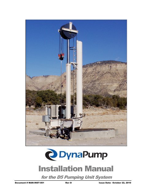
<strong>Installation</strong> <strong>Manual</strong>for the D5 Pumping Unit SystemDocument # MAN-INST-001 Rev D Issue Date: October 22, 2010
REV A (05-01-09)INSTALLATION MANUAL – D5DynaPump, Inc.Corporate Headquarters:2441 High Timbers Suite 200The Woodlands, TX 77380(281) 973-0050Manufacturing and Technology Center:9324 Corbin AvenueNorthridge, CA 91324(818) 407-7577, FAX (818) 407-7578Website: www.dynapumpinc.comNOTE:The information contained in this document is the sole property ofDynapump Inc. Any reproduction in part or whole without writtenpermission is prohibited.Document # MAN-INST-001 Rev A Issue Date: May 1, 2009
REV D (10-22-10)INSTALLATION MANUAL – D5REVISION RECORDREV DATE SECTION DESCRIPTIONA 5-01-09 - Initial ReleaseB 6-10-09C 10-01-10D 10-22-105App AApp B44444AB34CPage 21: Update crane selection criteria (step 2)Page 22: Add step for oil check in CWT site glass (step 4)Figure A-2: Replace pumping unit figure with currentFigure B-1: Update <strong>Installation</strong> Checklist to add item 42Page 3: Change part number for installation & interface kitPage 4: Corrected dimension of concrete piersPages 1-15: Update pumping unit componentsPages 23-28: Add new section: “Pre-installation Well HeadVerification”Pages 30-32: Update cylinder alignment requirementsPage A-3: Corrected dimensions on Figure A-3Pages B-2, B-3: Update <strong>Installation</strong> ChecklistPage 6-8: Update tools and special equipmentPage 41: Add external shutdown circuitry optionAdd Appendix C for historical configurationsREVISION RECORD
REV D (10-22-10)INSTALLATION MANUAL – D5Table of ContentsSECTION 1. INTRODUCTION .............................................................. 2Scope of Document.......................................................................................................................... 2Description of Basic Components .................................................................................................... 2Pumping Unit .................................................................................................................................. 2Power Unit ...................................................................................................................................... 3SECTION 2. SITE PREPARATION ....................................................... 4Piers Setup ....................................................................................................................................... 5Skid <strong>Installation</strong> and Pumping Unit Placement ................................................................................ 5SECTION 3. TOOLS AND SPECIAL EQUIPMENT ................................ 6Recommended Tools ....................................................................................................................... 6Computer Equipment ....................................................................................................................... 7DynaPump Equipment ..................................................................................................................... 7Special Equipment ........................................................................................................................... 7First Aid Equipment .......................................................................................................................... 7Safety Equipment ............................................................................................................................. 8Hydraulic Oil Specifications ............................................................................................................. 8SECTION 4. UNPACKING AND PUMP UNIT PREASSEMBLY ............. 9Shipment Types ............................................................................................................................... 9Pumping Unit Final Assembly ........................................................................................................ 10Power Unit ...................................................................................................................................... 21Transportation of Assemblies to the Site ....................................................................................... 21SECTION 5. INSTALLATION ............................................................. 22Pumping Unit .................................................................................................................................. 22Pre-installation Well Head Verification ........................................................................................... 24Power Unit ...................................................................................................................................... 34Final Assembly ............................................................................................................................... 35Checking Phase Orientation of Wiring ........................................................................................... 40External Shutdown Option ............................................................................................................. 41SECTION 6. DYNAPUMP SERVICE .................................................. 42Service ........................................................................................................................................... 42Repair and Replacement Parts Service ......................................................................................... 42APPENDIX A - SITE LAYOUT & INSTALLATION DRAWINGS .......... A-1APPENDIX B - INSTALLATION CHECKLIST .................................... B-1APPENDIX C - HISTORICAL CONFIGURATIONS ............................. C-1i
REV D (10-22-10)INSTALLATION MANUAL – D5List of FiguresFigure 1. Relative Positioning of Piers, Skids and Pumping Unit .................................................... 4Figure 2. Piers Setup ....................................................................................................................... 5Figure 3. Installing Celesco Transducer Assembly ....................................................................... 10Figure 4. Aligning the Cylinder (Base side shown) ....................................................................... 10Figure 5. Securing the Cylinder (Base Side) ................................................................................. 10Figure 6. Securing the Cylinder (Pulley Side) ............................................................................... 11Figure 7. Installing the Wiper Ring ................................................................................................ 11Figure 8. Installing Wiper Tabs ...................................................................................................... 11Figure 9. Installing Cable Sheaves ................................................................................................ 12Figure 10. PVC and Downpipe Connection ................................................................................... 12Figure 11. Hoisting Pulley Assembly ............................................................................................. 12Figure 12. Attaching L-bracket ...................................................................................................... 13Figure 13. Pulley <strong>Installation</strong> in Cylinder ....................................................................................... 13Figure 14. Inserting the Chain through PVC Pipe ......................................................................... 13Figure 15. Passing the Chain through Transducer Sprockets ...................................................... 14Figure 16. Securing the Snap Spring ............................................................................................ 14Figure 17. Terminating Chain with Counterweight ........................................................................ 14Figure 18. Securing the Counterweight ......................................................................................... 15Figure 19. Position Sensor and Sensor Bracket ........................................................................... 15Figure 20. Transducer Wiring ........................................................................................................ 15Figure 21. Cable Attachment Location on Power Unit .................................................................. 16Figure 22. Cable <strong>Installation</strong> .......................................................................................................... 16Figure 23. Routing the Pulley ........................................................................................................ 16Figure 24. Cable Routing Diagram ................................................................................................ 17Figure 25. Routing Cable under Sheave ....................................................................................... 17Figure 26. Finalized Pulley Routing ............................................................................................... 18Figure 27. Installing Wedge Sockets and Cable Clamps .............................................................. 18Figure 28. Leveling Feet on Base ................................................................................................. 18Figure 29. Assembled Field Unit with Stowed Carrier Bar ............................................................. 19Figure 30. Pressurizing Counterweight Charge Valve .................................................................. 19Figure 31. Brace Removal on Base Unit ....................................................................................... 20Figure 32. Hydraulic Tank Location ............................................................................................... 21Figure 33. Lifting the Pumping Unit ............................................................................................... 22Figure 34. Site Glass ..................................................................................................................... 23Figure 35. Typical Well Appearance ............................................................................................. 24Figure 36. Well Design Requirements ........................................................................................... 24Figure 37. BHP Plunger Spacing ................................................................................................... 25Figure 38. Pulley to Carrier Bar Distance ....................................................................................... 25Figure 39. Barrel to Plunger Length Distance ................................................................................ 26Figure 40. Improper <strong>Installation</strong> Scenarios ..................................................................................... 29Figure 41. Skid System ................................................................................................................. 30Figure 42. Cylinder Alignment: Verticality ..................................................................................... 31Figure 43. Cylinder Alignment: Verticality Adjustment .................................................................. 31Figure 44. Cylinder Alignment: Side-to-Side (and Front-Back) ..................................................... 32Figure 45. Cylinder Alignment: Side-to-Side (and Front-Back) Adjustment .................................. 32Figure 46. Cylinder Alignment: Setback Distance ......................................................................... 33Figure 47. Power Unit to Pumping Unit Connections .................................................................... 35Figure 48. Hydraulic Hose Connections ........................................................................................ 36i
REV (10-22-10)INSTALLATION MANUAL – D5List of Figures (Cont'd)Figure 49. Oil Return Hose Connections ....................................................................................... 37Figure 50. Head Leakage Hose Connections ............................................................................... 37Figure 51. Actuator Hose Connections ......................................................................................... 37Figure 52. Transducer Hose Connections ..................................................................................... 38Figure 53. Detaching the Solenoid Valve Coil ................................................................................ 38Figure 54. Oil Cooler Fan Motor Starter ........................................................................................ 40Figure 55. Oil Cooler Fan .............................................................................................................. 40Figure 56. MCCB L1-L2-L3 Connections ...................................................................................... 40Figure 57. Electrical Panel Location of Shutdown Circuitry .......................................................... 41Figure 58. External Circuit Connection on Terminal Block ............................................................ 41ii
REV A (05-01-09)INSTALLATION MANUAL – D5Section 1. IntroductionScope of DocumentThis document is broken down into several sections:Section 1 - IntroductionSection 2 - Site PreparationSection 3 - Tools and Special Fixtures RequiredSection 4 - Unpacking and Pumping Unit PreassemblySection 5 - <strong>Installation</strong>Section 6 - Dynapump ServiceAppendix A - Site Layout and <strong>Installation</strong> DrawingsAppendix B – <strong>Installation</strong> ChecklistAppendix C – Historical ConfigurationsDescription of Basic ComponentsSECTION 1 – INTRODUCTIONThe DynaPump system is comprised of two basic components:the Pumping Unit, and the Power Unit. Figure A-1 shows aninstalled unit.The Pumping Unit is comprised of a single hydraulically actuatedoil-filled cylinder, assisted by one or two nitrogen-filledcounterweight units, which work to apply the large up/downforces required at the well site. The technology incorporates realtimepump-off controller logic and provides real-time monitoringof well and/or pump performance status.The Power Unit is the control center that provides the ability toconvert electrical energy to hydraulic power and to control pumpstroke as needed to provide optimum pumping efficiency.Pumping UnitThe Pumping Unit stands over the wellhead and attaches to the polished rod by means of a carrierbar. The Pumping unit comes in various sizes, depending on the maximum load likely to beencountered. The <strong>Model</strong> 5 Pumping Unit is designed for a maximum lifting load of 15,000 pounds,and provides a maximum stroke of 168 inches. The Unit is comprised of a patented triple chamberhydraulic cylinder, heavy duty structural base, two large cylinders containing nitrogen gas underpressure, and a pulley/cable lift mechanism which doubles sucker rod stroke relative to cylinder travel.The nitrogen gas supply is connected to the cylinder counterweight chamber and serves as acounterbalance, basically to offset the rod weight and a portion of the fluid load. The counterbalancelift force can be adjusted at the well simply by adjusting the pressure of the gas in the storage cylinders.The direction and speed of the pump is then controlled by sending hydraulic fluid under pressure toeither the up or the down chambers of the cylinder.2
REV C (10-01-10)INSTALLATION MANUAL – D5Since the pump is computer controlled, the speed and stroke limit can be independently established inboth directions, thereby allowing for fast up strokes and slower down strokes. This feature greatlyincreases pumping efficiency for deep wells.The pump utilizes many feedback mechanisms to provide optimum stroke control and fullmonitoring of well and pump conditions. Feedback sensors on the pump include a linear sensor tomeasure stroke position and a proximity switch to detect a possible cable break.The Pumping Unit is mounted on a skid system that allows the pump to be retracted from thewellhead without requiring it to be disassembled. This feature allows maintenance crews to retract thepump using a winch in the event that maintenance is required on the well.The unit consists of these assemblies:D5 - Pumping Unit AssemblyK851 (E15A/E25A) and K854 (E40A)- Interface KitK903 – General <strong>Installation</strong> KitP601 – Piers <strong>Installation</strong> KitP611 (E15A/B, E25A/B) or P612 (E40A) – Base <strong>Installation</strong> KitPower UnitThe Power Unit provides the driving force and control for the Pumping Unit. It is comprised of twomajor components: a Hydraulic Pump System, and a Control & Communications Center. TheHydraulic Pump System includes electric motors which drive fixed displacement pumps. The systemincludes a sealed hydraulic reservoir and various valves and sensors that allow the patented triplechamber cylinder to function correctly. The Hydraulic Pump System is connected to the PumpingUnit by means of two primary high-pressure hoses and four secondary control/feedback hoses.The Control and Communications Center consists of solid-state electronics and motor controllers,which are designed for maintenance free operation. The electronics include computer controls thatallow for the pump to be controlled by feedback for precise operation of stroke speed and position.The computer is also designed to communicate externally by means of a modem, a radio transmitter,or by using a direct telephone line. This allows the pump to be remotely monitored and controlled.Power Unit Assemblies are as follows:Part Number Description Motor HP Input Voltage PhaseE15AE25AE40APower Unit 15HP/480VAC/3PHPower Unit 25HP/480VAC/3PHPower Unit 40HP/480VAC/3PH152540480480480333SECTION 1 – INTRODUCTION3
REV D (10-01-10)INSTALLATION MANUAL – D5Section 2. Site PreparationThis section discusses how to prepare the well site for Dynapump equipment.Observe the following safety precautions:Safety Precautions• When hoisting or moving components or assemblies, always use a crane or forklift rated forthe load being lifted or supported.• Personal safety equipment should be worn (e.g. hard hat, steel-toe shoes, boots, etc.)Dynapump pumping unit equipment is mounted on a series of four rectangular concrete platforms,referred to as piers. There are three piers for the pumping unit, and one for the power unit.The three pumping unit piers are dimensioned 18” x 18” x 131” and are positioned at a preestablisheddistance from each other in accordance with Figure A-3. The power unit pier isdimensioned 108” x 96” and is placed 2 to 10 inches from the pumping unit pier as shown in FigureA-3.After the piers have been positioned, mounting skids and the pumping unit itself are carefully alignedover the piers and then secured.Figure 1 shows the relative placement of the piers, skids and pumping unit.PumpingunitPier forpower unitPowerunitPier forpumping unitSkid forpumping unitFigure 1. Relative Positioning of Piers, Skids and Pumping UnitSECTION 2 – SITE PREPARATION4
REV A (05-01-09)INSTALLATION MANUAL – D5Piers SetupThe foundation that equipment is mounted over is typically pre-cast per Dynapump requirements,but also may be poured in place.Perform the following steps:1. Grade the site (approx. 25’ x 25’) and scrape all dirt/debris off existing well pad or levelnominal ground level.2. Provide adequate drainage by allowing excess water to drain. Poor drainage may result in thefoundation settling unevenly, causing undue stresses in the foundation. This may cause pumpmisalignment after a period of time.3. Excavate an area deep enough to position pre-cast concrete piers per the layoutrequirements. Foundation design/soil improvement is based on soil conditions at the wellsite, and the owner asumes full responsibility of the design/quality of the foundation.Pumping UnitPower UnitFigure 2. Piers Setup4. Add enough aggregate base to create a height of 36 inches between the wellhead and the topof the nominal pier level (see Figure A-2). The minimum height will assure full stroke lengthof the pumping unit.5. Lower the pre-cast piers into the aggregate base using a crane or other hoist equipment (seeFigure 2).6. When finalizing the pier placement, verify that no concrete material hangs over the aggregatesoil unsupported, and that the pumping unit will be able support full load bearing capabilityfrom the pumping unit. Site layout is based upon soil bearing strength of 6000 psf.7. Position the pad in accordance with Figure A-3.Skid <strong>Installation</strong> and Pumping Unit PlacementSkid mounting and pumping unit site installation must be performed at the same time to assureaccuracy in equipment placement. The paragraph in Section 5 “<strong>Installation</strong>” titled, “Skid Unit<strong>Installation</strong> and Placement of the Pumping Unit” describes this procedure.SECTION 2 – SITE PREPARATION5
REV D (10-22-10)INSTALLATION MANUAL – D5Section 3. Tools and Special EquipmentThis section lists required tools and special fixtures required for assembly.The following provides a list of equipment and tools needed to complete assembly of the DynaPumpUnit. Most of these tools should be available locally. If tools are unavailable, please contact yourDynaPump sales representative for a quotation on a particular item or items.Recommended Tools• Channel locks – ranging from 6.5-inch, 10-inch and 20-inch.• End wrench set, standard sizes, US and Metric• Allen wrench set, US and Metric• Adjustable wrench – 24-inch• Monkey wrenches – 15-inch and 18-inch• Wire strippers, wire cutters and crimpers• Screwdriver set, standard and electronic (small size), phillips and flat blade• Diagonal cutting pliers, 8-inch• Deep impact gun, 3/4-inch drive, 1 1/4-inch deep-impact socket• A set of 3/4-inch drive sockets, including 1 5/8-inch• A set of 1/2-inch drive sockets that range from 3/8-inch to 1-1/4-inch• Drill set, cordless, with drill bit set 1/16-inch to 1/2-inch reduced shank• Thread restoring tool and tap set• Hacksaw• Utiity knife• Sledge hammer, 3-pound• Tape measure, 36-inch• Punch/chisel set• Vice grip or bench vise, capacity to hold 5-inch• Measuring level, liquid, 2-inch• Shovel• Circuit multimeter (with case), digital or analog, with electrical tester and amp probe• Chain with hook ends• Strap wrench vice grip• Zerk fitting, 1/8-inch (pkg 10)• Cable cutter• Tool box, side mount• Tool box, pack ratSECTION 3 – TOOLS & SPECIAL EQUIPMENT6
REV D (10-22-10)INSTALLATION MANUAL – D5Computer Equipment• Laptop computer, equipped with Microsoft-equivalent Office software• Ladder logic software (current installed versions)• Service Tech CD (current version)• COM cableDynaPump Equipment• Counterweight fill hose (P/N DP00315)• Coupler alignment tool (No DP P/N)• Cover plate, 2-inch hose (P/N 200-2SAE108)• Cable removal tool (P/N D00166)• V-block dolly, 1 each• Base assembly supports, 2 each• Counterweight storage stand, 4 eachSpecial Equipment• Air compressor multiplier, 5 to 1 ratio• Open capstan winch, rated at 800 pound pulling capacity• Wire cable puller for 9/16-inch cable, rated at 500 lbs pull force• Braided rope, 250 feet of 1/2-inch poly Dacron or polyester• Forklift or mobile crane rated at 21,000 lbs lifting capacity• Stationary crane with two trucks, each rated at a minimum lifting capacity of 7,000 lbs. The minimumcrane runway dimensions should be 10 x 40 feet with a lifting height capability of at least 8 feet.• Air compressor rated at 50 cfm @120 psi. The compressor must have a dryer installed so that thereis no water in the delivered compressed air.• Electric-powered portable grinding tool• Ratchet chain hoist, rated at 3000-pounds• Hydraulic jack, bottle, 12-ton• Locks, keyed alike (order qty 4 min)First Aid Equipment• First aid kit• H 2 S Monitor for toxicity• Fire extinguisher, ABC-typeSECTION 3 – TOOLS & SPECIAL EQUIPMENT7
REV D (10-22-10)INSTALLATION MANUAL – D5Safety Equipment• Harness, climbing (front D-ring)• Lanyard, rope positioning, and tag line• Tags, lock-out, vinyl• Hasps, safety lockout• Glasses, safety Z-28 type• Gloves, protective leather• Boots, steel-toe• Hat, construction, hard plastic• Ear plugsNOTE: OSHA Safety training must be up-to-date and cover the following:• Pass port safety training• H 2 S• Haz Com• Respiratory protection• First-aid/CPRHydraulic Oil SpecificationsCharacteristicSECTION 3 – TOOLS & SPECIAL EQUIPMENTTable 1. Hydraulic Oil SpecificationsTexaco RandoHDZ 328Mobil DTE13MShell TellusT32ChevronRykon 32Oxidation Stability HIGH VERY GOOD VERY GOOD HIGHCorrosion Protection VERY GOOD VERY GOOD GOOD VERY GOODViscosity Index HIGH HIGH VERY HIGH HIGHAntiwear Properties VERY GOOD VERY GOOD GOOD VERY GOODAnti-Foaming Additive(s) YES YES YES YESWater Separation FAST GOOD GOOD FASTIndustry SpecificationsVickers I-286-S YES YES NO YESVickers M-2950-S YES YES NO YESVickers 35VQ-25 YES NO NO YESRacine <strong>Model</strong> S YES NO NO YESCincinnati Machine P-68, P-69, P-70 YES NO NO YESDenison HF-0, HF-2 YES NO NO YESFZG Gear Test, DIN 51534 - Fail Stage NO 11 NO NOFLUID DATAISO Viscosity Grade 32 32 32 32Kinematic Viscosity, cSt@40°C 30.4 32.0 32.4 32.0Kinematic Viscosity, cSt@100°C 6.1 6.1 6.4 6.3Viscosity Index 153 141 155 153Flash Point, °C(°F) 220(428) 210(410) 160(320) 220(428)Pour Point, °C(°F) -50(-58) -45(-49) -45(-49) -50(-58)
REV A (05-01-09)INSTALLATION MANUAL – D5Section 4. Unpacking and Pump Unit PreassemblyThis section discusses unpacking, and preassembly requirements (if required) after shipment.NOTE:If the unit is shipped within North America, preassembly has likely beencompleted. The operator can skip Section 4: Unpacking and PumpingUnit Preassembly and proceed to Section 5: <strong>Installation</strong>, then continuewith each process until commissioning of the unit has been completed.Shipment TypesDynapump Pumping systems may be shipped in two ways according to location:• Domestic (North America) - Arrives by flatbed truck, pump units are preassembled andready for installation• International – Arrives packaged in a shipping container, and pump units must beassembled in accordance with this manual.When the shipping container arrives, verify that the contents match the shipping documents.Carefully unpack the container using either a crane or a forklift rated for 8,000 pounds. Remove thesmaller parts and packages first, followed by the large structural base, counterweights units, hydrauliccylinder, and the Power Unit. Each shipping container may contain parts or assemblies for more thanone pump.SECTION 4 – UNPACKING AND PUMP UNIT PREASSEMBLY9
REV (-01-)INSTALLATION MANUAL – D5Pumping Unit Final AssemblyNOTE:Use an overhead crane (rated at 21,000 lbs) when moving the completedassembly to prevent damage to either nylon pulleys or hydraulic cylinder.Complete final assembly in accordance with the following steps:1. Install the transducer into the cylinder support using two 5/16-inch screws (see Figure 3).TransducerMountingscrews (2x)Figure 3. Installing Celesco Transducer Assembly2. While the cylinder is supended, align the cylinder assembly to the base and counterweightstructure by positioning the cylinder bolt holes with the holes in the base (see Figure 4).Base side ofcylinderBolt holes(4X)CylinderFigure 4. Aligning the Cylinder (Base side shown)3. Secure the cylinder to the base structure using four 1-1/4 x 3-inch bolts and lockwashers. Use anti-seize compound on the bolt thread (see Figure 5).Base structuresideCylinder bolts(upper)Cylinder bolts(lower)Figure 5. Securing the Cylinder (Base Side)SECTION 3 – TOOLS & SPECIAL EQUIPMENT10
REV A (05-01-09)INSTALLATION MANUAL – D54. Secure the pulley side of the cylinder using two 1-inch x 2-1/2- inch bolts, four flatwashers, two 1-inch lock washers and nuts (see Figure 6).Pulley sideCylinderCylinder bolts(2x)Figure 6. Securing the Cylinder (Pulley Side)5. Install a rubber wiper with inserted o-ring onto the cylinder (see Figure 7).Wiper ando-ringFigure 7. Installing the Wiper Ring6. Loosen cylinder attach bolts, and install wiper tabs over the bolts to secure thewiper ring to the cylinder shaft, then retighten attach bolts (see Figure 8).WiperFigure 8. Installing Wiper TabsSECTION 3 – TOOLS & SPECIAL EQUIPMENT11
REV A (05-01-09)INSTALLATION MANUAL – D57. Mount four cable sheaves to the tension plate. Secure with two 1-1/8 hex cap screws 6-inches long, and four 1-1/8-inch flat washers, and two lock washers and nuts. Install four3/8-inch roll pins into the plate with a hammer (see Figure 9).BaseCablesheavesRoll PinFigure 9. Installing Cable Sheaves8. Mount a PVC pipe below the downpipe, and secure the upper and lower counterbracessegments, attaching the two pieces together with bolts (see Figure 10).DownpipePVCpipeCounterbraceFigure 10. PVC and Downpipe Connection9. Hoist the pulley assembly using a metal support rod through a pair of 2-inch holes locatednear the top of the pulley support (see Figure 11).CablehoistPulleyFigure 11. Hoisting Pulley AssemblySECTION 3 – TOOLS & SPECIAL EQUIPMENT12
REV (-01-)INSTALLATION MANUAL – D510. Attach the L-shaped bracket to the pulley support using 7/16-inch screws (see Figure 12).PulleysupportL-shapedbracketFigure 12. Attaching L-bracket11. Align the hole through the pulley support with the threaded hole in the cylinder. Securepulley assembly using the existing cylinder 1 1/2-inch bolt and lock washer. Tighten boltwith the impact wrench (see Figure 13).Cylinder(ref)Pulley(ref)Pulley SupportMounting BoltFigure 13. Pulley <strong>Installation</strong> in Cylinder12. Feed a metal wire attached to the chain on the base side, and slowly feed the attachedchain links through the PVC pipe (see Figure 14).Metal wireFigure 14. Inserting the Chain through PVC PipeSECTION 3 – TOOLS & SPECIAL EQUIPMENT13
REV C (10-01-10)INSTALLATION MANUAL – D513. Loosen the transducer mounting bracket to feed the chain over the sprockets of thetransducer. When the chain meshes with the sprockets, reattach bracket (see Figure 15).MountingbracketChainFigure 15. Passing the Chain through Transducer Sprockets14. Stretch the chain through the cylinder bracket and around the L-shaped bracket on theother side to install the snap spring into bracket (see Figure 16).L-shapedbracketSnapspringFigure 16. Securing the Snap Spring15. Terminate the base side of the chain by attaching a counterweight (see Figure 17).Counterweightfor chainFigure 17. Terminating Chain with CounterweightSECTION 4 – UNPACKING AND PUMP UNIT PREASSEMBLY14
REV C (10-01-10)INSTALLATION MANUAL – D516. On the other (base) end of the down pipe, secure the counterweight with a bent wire andattach to the back of the pipe (see Figure 18).Figure 18. Securing the Counterweight17. Install the position sensor and bracket assembly to the tension bar (see Figure 19).SensorbracketSensorPositionsensor cableFigure 19. Position Sensor and Sensor Bracket18. Electronically connect the transducer cable (see Figure 20).TransducercableFigure 20. Transducer WiringSECTION 3 – TOOLS & SPECIAL EQUIPMENT15
REV C (10-01-10)INSTALLATION MANUAL – D519. Note the attachment points on the Power Unit for the transducer and position sensor.This connection will be performed during final installation (See Figure 21).TransducerconnectionPosition sensorconnectionFigure 21. Cable Attachment Location on Power Unit20. Begin installation of the pulley tension rope by stringing the 7/16-inch cable from the rollthrough the base. The pumping unit requirement is for 140 feet of cable (70 ft perpulley). See Figure 22.Pulley tensionropeFigure 22. Cable <strong>Installation</strong>21. Route the cable through the innermost groove of the first pulley (see Figure 23).Cable thrufirst pulleyFigure 23. Routing the PulleySECTION 3 – TOOLS & SPECIAL EQUIPMENT16
REV A (05-01-09)INSTALLATION MANUAL – D522. Using Figure 24 as a general guide for cable routing.Figure 24. Cable Routing Diagram23. Route the cable under the sheave of the first pulley to the underside of the sheave to theon the other sheave on the opposite side of the cylinder (see Figure 25).Figure 25. Routing Cable under SheaveSECTION 4 – UNPACKING AND PUMP UNIT PREASSEMBLY17
REV A (05-01-09)INSTALLATION MANUAL – D524. Route cable around the second pulley, and continue the process of cable routing untilboth pulleys are wired (see Figure 26).Pulley #2RoutingFigure 26. Finalized Pulley Routing25. Tie off the cables using the wedge sockets and cable clamps to secure the cable to thecable weldment (see Figure 27).WedgeSocketCableClampFigure 27. Installing Wedge Sockets and Cable Clamps26. Install leveling feet to the base of unit and apply anti-seize grease (see Figure 28).Anti-seizecompoundFigure 28. Leveling Feet on BaseSECTION 3 – TOOLS & SPECIAL EQUIPMENT18
REV A (05-01-09)INSTALLATION MANUAL – D527. An example of an asembled unit appears as follows in the field (see Figure 29).CableWeldmentTensionBarFigure 29. Assembled Field Unit with Stowed Carrier Bar28. Remove the 3/8-inch cap on the charge valve assembly and connect the charge port to anair pressure source capable of filling the pipe to 1000 psi (see Figure 30).WARNING:Cylinder gas pressure can be manually released in a non-operating stateby opening the bleeder valve on top of the actuator. Opening this valveslowly will release any load the ram may be carrying and enable the ram toreturn safely to its full down position. The valve should be open only whilerunning under normal conditions to prevent the ram from acceleratingthrough to its fully extended position when loads are disconnected.Charge valveCounterweightunitAir pressuresourceFigure 30. Pressurizing Counterweight Charge Valve29. Repressurize the counterweight unit to the pressure established based on well loadingconditions. Depending on variances in pump size and power unit requirements, unitsmay need to add or bleed off some pressure. If shipped domestically, units are initiallypressurized to 600 psi.SECTION 3 – TOOLS & SPECIAL EQUIPMENT19
REV A (05-01-09)INSTALLATION MANUAL – D530. Allow the pressure in the counterweight to equalize with the compressor pressure prior tostarting the pressure amplification phase.31. Monitor the 3/8-inch and 1 1/2-inch fitting connections for leaks during the fillingprocess by applying soapy water and looking for bubbles. Verify that the ball valves areopen when monitoring for leaks to test the downstream fittings up to the cap.32. Grind off the brace on the base using a portable electric grinding tool (see Figure 31).BraceFigure 31. Brace Removal on Base Unit33. Once the pipe is charged, close the charge ball valve and terminate charging process.34. Reinstall the 3/8-inch cap to the charge valve assembly.35. The assembly may now be moved by placing the V-block dolly under the pulley end ofthe counterweight and the using a forklift to tow the other end by attaching to the basecross member using the holes provided.SECTION 3 – TOOLS & SPECIAL EQUIPMENT20
REV A (05-01-09)INSTALLATION MANUAL – D5Power Unit1. Load the hydraulic oil tank with 28 gallons for 25HP or 40 HP power unit systems of oil.2. Load the hydraulic oil tank with 10 gallons for systems with 15 or 25 HP power units ofoil. See Figure 32 for tank location.Hydraulictank fillFigure 32. Hydraulic Tank LocationTransportation of Assemblies to the SiteGeneral guidelines are as follows:NOTE:The ship kit box can be stored separately by the driver in a truck locationwhere it doesn't get damaged.• Load the assembled pumping unit on the trailer.• Place blocks on the trailer for the pumping unit to rest on.• Securely tie ropes or other fastening materials around the pipe and over the base. Make surethe ties are not binding on the cylinder.• Load the ladders and the skid system.• Load the power unit on the front of the trailer. The driver can tie down the power unit overthe top of the frame.SECTION 3 – TOOLS & SPECIAL EQUIPMENT21
REV A (06-10-09)INSTALLATION MANUAL – D5Section 5. <strong>Installation</strong>This section discusses final assembly and installation of pumping and power unit assemblies.The following are safety precautions:Safety Precautions• When hoisting or moving components or assemblies, always use a crane or forklift ratedfor the load being lifted or supported.• Personal safety equipment should be worn (e.g. hard hat, steel-toe shoes, boots, etc.)• Ensure that chains and cable slings used in the erection of the system have a load testcertification tag suitable for the load being lifted.Pumping UnitThe Pumping Unit will be delivered to the well site on a flat bed truck.1. Unload the pumping unit from the flat bead truck with a 3-point sling, and placehorizontally on a flat surface.2. Erect the pumping unit with a crane capable of lifting 10,000 lbs. The crane should havea nominal reach capable of maintaining a minimum hook height of approximately 20 feet.(see Figure 33).Figure 33. Lifting the Pumping Unit3. Retrieve the two auto lubbers, P/N 155-1, from the installation kit to maintain a constantflow of grease to the pulley support bearings. The process keeps contamination frommigrating into bearings during normal operation.4. Install the auto lubbers in the grease ports on the top of the pulley support mounted onthe very top of the cylinder (between the two nylon pulleys).5. Activate the auto lubbers by turning the switch to the “On” position. Verify activationby confirming that the indicator light on each lubber is functioning.SECTION 5 – INSTALLATION22
REV B (06-10-09)INSTALLATION MANUAL – D56. Verify through the site glass (see Figure 34) that hydraulic oil is present in thecounterweight unit. The oil will have a clear to yellow appearance and the metallic surfacewill have a sheen. If the counterweight appears empty, refill the hydraulic tank (see“Power Unit”.Site GlassFigure 34. Site GlassSECTION 5 – INSTALLATION23
REV C (10-01-10)INSTALLATION MANUAL – D5Pre-installation Well Head VerificationSeveral checks must be made after the construction has been finalized by the bottom hole pumpinstaller and before the DynaPump unit is positioned in place by service personnel. Theseverifications ensure that the maximum surface and downhole stroke for the pumping unit is available,and that no damage will occur to the cylinder, stuffing box or bottom hole pump.NOTE:Review the down hole detail from the rig contractor to obtain thepolish rod length and bottom hole pump stroke capacity. Thisimportant data will be used to calculate predicted loads.This is what a typical well looks like after it has been installed (see Figure 35).NOTE:Polished rod is in place and therod string is spaced off thebottom, supported by the rodclamp, which is resting on astuffing box.Rod clampFlow linesBottom hole design requirements are as follows:Figure 35. Typical Well Appearance1. Well head height should NOT be higher than the height of the bottom of the cylinder if thepumping unit would have been on piers. This distance, shown as distance “A” from the stuffingbox to the top of the piers, is approximately 50 inches. If it appears that the height of thepumping unit is not tall enough, more aggregate should be poured to increase the height. SeeFigure 36.WellheadheightI-beamstructureAggregateSECTION 5 – INSTALLATIONFigure 36. Well Design Requirements24
REV C (10-01-10)INSTALLATION MANUAL – D52. The polished rod must be long enough to allow full travel of the pumping unit withouthaving the coupler to the first sucker rod come in contact with the stuffing box. Thisdistance should also be long enough to extend above the stuffing box for attachment ofthe carrier bar, polish rod clamp, plus the clearance between the top of the stuffing boxand the bottom of the carrier bar (see Figure 37).Polished rodBHP plungerresting on bottomFigure 37. BHP Plunger Spacing3. Distance between the pulley assembly and carrier bar must be longer than the desired strokelength (see Figure 38).PulleyCarrier barPulley-to-Carrier barDistanceFigure 38. Pulley to Carrier Bar DistanceSECTION 5 – INSTALLATION25
REV C (10-01-10)INSTALLATION MANUAL – D54. The relationship between the barrel and plunger length must exceed the surface strokecapacity. For example, a <strong>Model</strong> 5 has a 168” surface stroke. The bottom hole pump(BHP) barrel is 240” long. The BHP plunger is 48”. The effective stroke length is 192”.Therefore, the BHP stroke capacity is 24” longer than the surface stroke capacity. SeeFigure 39.For a model 5 pumping unit, the following specifications exist:Specified strokelengthPlunger travel for strokelength (2:1 ratio)Available plungertravel (inches)Plunger margin at fullstroke (inches)168 84 90.5 6.5Figure 39. Barrel to Plunger Length DistanceSECTION 5 – INSTALLATION26
REV C (10-01-10)INSTALLATION MANUAL – D5Stacking out the Rod String to Verify and Position BHP Plunger off the BottomNOTE: This procedure requires the DynaPump system to be completely installed, hoses connectedbetween the Power and Pumping Unit, the cylinder bled of any air, carrier bar position properlyadjusted in relation to the well head and the cylinder ball valves open.Perform these steps:1. Attach the polished rod clamp close to the top of the polished rod to assure the string willstack out before the carrier bar comes into contactwith the stuffing box.2. Connect a nitrogen bottle and fill hose to the fill portadjacent to the counterbalance actuator valve.3. Slowly add nitrogen. The carrier bar will slowly slideup the polished rod and eventually lift the rod stringand lower clamp off the stuffing box.4. Loosen, but don’t remove, the clamp that wassupporting the rod string on the stuffing box.5. Make sure the fill valve on the pumping unit is closedand the valve on the nitrogen bottle is closed, then remove the hose.6. Slowly open fill/drain port. As nitrogen bleeds off,the carrier bar slowly moves down.7. Continue bleeding pressure until the carrier barmoves slighly down below the clamp.8. At this point, the rod string is stacked out, meaningthe BHP plunger is resting at the bottom of theBHP barrel.9. Tighten the clamp that is resting on the stuffing boxjust enough in,so it moves with the rod string as it islifted up.10. Reconnect the nitrogen bottle and fill hose to the fill port.11. Slowly add nitrogen, and continue to add as the rod string moves upward.12. Note the space being created between the stuffing box and the bottom of the clamp.13. Continue to add nitrogen to move the rod string upuntil the desired measurement is achieved., typically,one to two feet , depending on depth and anticipatedCarrier barrod stretch and dynamics.14. Loosen the clamp below the carrier bar. Slide itdown until it is resting on the stuffing box and thentighten to sustain the rod load.15. Make sure the fill valve on the pumping unit is closedand the valve on the nitrogen bottle is closed. Thenremove the hose.Polished rodclampPolished rodCarrier barStuffing boxNitrogen fillportPolished rodclampStuffing boxSECTION 5 – INSTALLATION27
REV C (10-01-10)INSTALLATION MANUAL – D516. Slowly open the fill/drain port. As the nitrogen bleeds off, the carrier bar will slowlymove down.17. Continue to bleed off the pressure until the rod string is supported by the clamp on thestuffing box.18. Continue to bleed off the nitrogen until the cylinder is fully retracted and the carrier bar ishanging, supported by the wire rope.19. Loosen the clamp above the carrier bar. Slide it down until it is resting on the stuffingbox and then tighten to sustain the load.20. Reconnect the nitrogen bottle and fill hose to the fill port.21. Slowly add nitrogen, and continue to add as the rod string moves up until the load issupported by the carrier bar and top clamp.22. Remove the clamp below the carrier bar.23. At this point, the cylinder and rod string are spaced properly.SECTION 5 – INSTALLATION28
REV C (10-01-10)INSTALLATION MANUAL – D5Typical Problems Related to Improper <strong>Installation</strong>Shown below are two improper installation scenarios caused by the pumping unit (bottom cap ofcylinder) being positioned lower than the well head. In each case, the pumping unit loses stroke length.CASE 1CASE 2Data (ex. <strong>Model</strong> 13):Maximum stroke available = 360’Actual carrier bar travel = 345’Resultant lost stroke length =Irrelevant because of damage--------------------------------------------Analysis:When the carrier bar is stacked onthe stuffing box with the 6-inchdistance requirement, the pulleyrope length is often shortened tocompensate.As a result, the carrier bar maycontact the pulley assembly -causing damage.WELL HEAD HEIGHT > BOTTOM CAP HEIGHTData (ex. <strong>Model</strong> 13):Maximum stroke available = 360’Actual carrier bar travel = 345’Resultant lost stroke length = 15’--------------------------------------------Analysis:The first portion of plunger travelwhen the cylinder is fully extendedhas been lost based on the amountof slack in the wire rope.As a result, the ability of the carrierbar to achieve full stroke length isirretrievably lost.Well head heightBottom cap of cylinderCASE 1: CARRIER BAR HITS PULLEYCASE 2: LOOSE WIRE ROPE CAUSES LOSS OF STROKEFigure 40. Improper <strong>Installation</strong> ScenariosSOLUTIONS:CASE 1 – Increase the aggegate (sand) level below the piers.CASE 2 – Tighten loose wire cable so it is not hanging. Unfortunately, this reduces the strokelength.SECTION 5 – INSTALLATION29
REV A (05-01-09)INSTALLATION MANUAL – D5Skid Unit <strong>Installation</strong> and Placement of the Pumping UnitThe skid system contains the rail framework on which the pumping unit rests and is mounted directlyover the concrete piers (See Figure 41).NOTE:<strong>Installation</strong> of the skid plates provides for coarse alignment of thepump relative to the wellhead. If rig work still needs to be done, thepumping unit should be mounted to the back of the skids.When the skid system is installed, the pumping unit can slide forward on the rails and be positioneddirectly over the wellhead. If the pumping unit is undergoing maintenance, or before commissioningtakes place, the unit is retracted to a safe postion at the rear end of the skid rails. There are stops onthe front and rear end of the skid to prevent the pumping unit from sliding off the rails and piers.See Figure 41.Skid systemFigure 41. Skid SystemPerform the following steps to install the skids:NOTE:Prior to placing the pump in position, be sure that the area is free andclear of any obstacles. Follow all standard oil field safety practiceswhile completing the installation. Ensure the well is not pressurized topreclude a serious accident if the wellhead is accidentally bumped.1. Slowly erect the pump using the crane until the pump is fully suspended from the crane.2. Use a 10-foot extension chain or sling to prevent the crane hook from hitting thecounterweights as they come to vertical position. The crane and attachment clevis mustbe rated at 25-ton to provide a safety margin.3. Align the pump over the skid mounting point so the pump is centered over the wellhead.SECTION 5 – INSTALLATION30
REV C (10-01-10)INSTALLATION MANUAL – D54. Support the V-frame base with two bottle jacks to lift the load off the outer skids, andthen secure the center skid to the concrete pier.NOTE: Steps 5 through 8 discuss cylinder verticality.5. Measure the side-to side and front and back verticality of the pump using a 2-footmagnetic bubble level. Place the bubble level on the cylinder wall, and also on anotherlocation, such as a smooth vertical surface on the bottom cap. See Figure 42.Figure 42. Cylinder Alignment: Verticality6. If the cylinder is not vertical, rotate the adjustable feet on each base leg as required tobring the cylinder to the vertical position. See Figure 43.Bubble levelAdjustmentfootFigure 43. Cylinder Alignment: Verticality AdjustmentSECTION 5 – INSTALLATION31
REV C (10-01-10)INSTALLATION MANUAL – D57. Perform a side-to-side measurement from the center of the cylinder to see if the feet areequidistant. Alternately, verify that the polished rod is centered on the cylinder centerline.See Figure 44.Polished rodFigure 44. Cylinder Alignment: Side-to-Side (and Front-Back)8. If the sides are not equidistant, use a chain to forcibly align the pumping unit. Alternately,a cheater bar may be applied on the skids to apply the proper torque for leverage. SeeFigure 45.ChainFigure 45. Cylinder Alignment: Side-to-Side (and Front-Back) AdjustmentSECTION 5 – INSTALLATION32
REV C (10-01-10)INSTALLATION MANUAL – D59. Verify that the setback distance from the centerline of the polished rod to the front edgeof the cylinder bottom cap is 17.5 ±.5 inches. This ensures that the cables will be in thesame plane as the polished rod. If the distance is incorrect, move the pump fore or aft asrequired to establish this distance. See Figure 46.SetbackdistanceFigure 46. Cylinder Alignment: Setback Distance10. Once the pumping unit is in position, perform a final align on the outer skids so that theextended feet from the pumping unit can slide easily into each outer skid.11. When each adjustment foot is centered on the skid pad, and the capture washer just clearsskid capture angle, install one bolt in front section. The feet should be screwed all the wayinto the base legs.12. Adjust the rear sections of outer skids so they are parallel and accommodate full trackback, and then bolt the outer skids in place.13. Remove the bottle jacks from the base.14. Install a safety chain on each leg of the base to the attach point on the side skid. Eachchain consists of approx. 14 inches of 1/4-inch grade 40 steel chain, a jaw & jawturnbuckle, and two each 3/8-inch anchor shackles, included in the <strong>Installation</strong> Kit.The Pumping Unit is now ready to be mated to the Power Unit and attached to the wellhead.SECTION 5 – INSTALLATION33
REV A (05-01-09)INSTALLATION MANUAL – D5Power UnitPower Units are shipped fully assembled and require no special assembly prior to normal operation.General ChecksThe following checks should be performed prior to delivery:• Visually check the assembly and touch up any paint areas that have been scuffed or chippedduring transport. Verify there is no damage to any of the exterior components.• Remove the motor mount covers and tighten the motor coupling setscrews. Visually verifythat the motors are properly aligned. Reinstall the motor mount covers.• Open the hydraulic cabinet and visually inspect for damage. Tighten all hose connections andfittings to make sure they are snug. Verify that the hydraulic oil level is near the top of thetank as shown on the glass scale. Close the cabinet and lock it.• Open the electrical cabinet and visually inspect for damage. Tighten all wire terminalconnections to make sure they are snug. Close the cabinet and lock it.1. Using a crane, lift the Power Unit using straps or chains connected to the lifting hooks onthe top of the unit. Maneuver the unit so it is positioned over the foundation pad withthe cooling fan facing the rear of the pad. Verify installation dimensions are correctbefore removing the crane hook.2. Ensure that the Power Unit C-channel bottom leg is flat on the concrete pad prior totightening the bolts. If not, add shims, as required, near the boltholes to prevent thepossibility of distorting the frame as the mounting bolts are tightened.3. Connect 480 volt 3-phase power to the unit at the disconnect safety switch. Thecustomer or their designated representative shall be responsible for this task to ensurethat the connection conforms to local rules and regulations. Once connected, make surethat power is locked out until pump installation is complete.4. Install a ground rod at least 6’ long on the side of the Power Unit near the green groundstrap to provide an earth ground to both the Pumping Unit and Power Unit.SECTION 5 – INSTALLATION34
REV A (05-01-09)INSTALLATION MANUAL – D5Final AssemblyPerform final hose and pumping unit structural connections (see Figure 47).Power Unit to Pumping Unit ConnectionsRefer to the following photos for connections between the Power Unit and the Pumping Unit.Pumping UnitHead LeakageCWT ActuatorUP cylinderCWT TransducerDOWN cylinderElectricalconnectionsCWT Oil ReturnPower UnitCWT ActuatorCWT Oil ReturnUP cylinderpressureHead LeakageCWT TransducerDN cylinderpressureFigure 47. Power Unit to Pumping Unit ConnectionsSECTION 5 – INSTALLATION35
REV A (05-01-09)INSTALLATION MANUAL – D5Install the following connections between the Power Unit and the Pumping Unit:WARNING:When installing hoses and connections, it is imperative that theconnection is clean on both ends. Any dirt or contaminationintroduced while making the connection can have an adverse affect onthe operation of the pump and may lead to pre-mature failure of thepump or cylinder.1. Attach Up and Down hydraulic hoses between the power and pump unit (Figure 48).UP hoseDOWNhoseUP hoseFigure 48. Hydraulic Hose Connections2. Remove the caps from the counterweight chamber on the cylinder.CAUTION:The cylinder might not be fully retracted due to pressure in thecounterweight unit, so remove cap slowly to prevent injury.3. Install one end of the Up chamber pressure hose to the power unit Up cylinder port, andthe other end to the pumping unit cylinder Up port.4. Rotate the hose so that it makes a smooth transition between the two units.5. Make sure that the o-ring is properly installed and that the four bolts on each fitting aretight to prevent leakage.6. Install one end of the Down chamber pressure hose to the power unit Down cylinderport, and the other end to the pumping unit cylinder Down port.7. Rotate the hose so that it makes a smooth transition between the two units. Make surethat the four bolts on each end are tight to prevent leakage. Torque the bolts to 65 ft-lbs.8. <strong>Manual</strong>ly open the Up and Down ball valves at the cylinder to allow the hydraulicpressure to equalize.9. Slowly bleed the air and then remove the protective cap on the cylinder air fitting. As theair pressure is bled, the cylinder ram slowly descends until it reaches the bottom stop.SECTION 5 – INSTALLATION36
REV A (05-01-09)INSTALLATION MANUAL – D510. Connect one end of the Oil Return hose to the Power Unit and the other end to the 3/8-inch fitting on the front counterweight charge valve (See Figure 49). Torque to 35 ft-lbs.Once the hose is connected, open the charge ball valve.Power UnitCounterweight UnitOil ReturnhoseOil ReturnhoseFigure 49. Oil Return Hose Connections11. Connect the Head Leakage hose to the power unit. This hose that connects to the verytop of the cylinder (see Figure 50). Torque the fitting to 50 ft-lbs.Power UnitCylinderHead LeakagehoseHead LeakagehoseFigure 50. Head Leakage Hose Connections12. Connect the Actuator hose from the Power Unit to the 1/2-inch JIC fitting on the frontcounterweight actuator (See Figure 51). Torque fitting to 50 ft-lbs.Power UnitCounterweight UnitTransducerhoseActuatorhoseActuatorhoseTransducerhoseFigure 51. Actuator Hose ConnectionsSECTION 5 – INSTALLATION37
REV A (05-01-09)INSTALLATION MANUAL – D513. Install the counterweight transducer hose from the power unit to the 3/8-inch JIC ballvalve fitting on the front counterweight actuator. This hose allows the air pressure inthe cylinder air up chamber to be measured. See Figure 52.TransducerhoseFigure 52. Transducer Hose Connections14. Verify that the ball valves are open when monitoring for downstream fitting leaks duringthe filling process by applying soapy water and looking for bubbles.15. Once the unit is charged, close the charge ball valve and terminate the charging process.16. Detach the solenoid coil from the control manifold block by loosening the attachmentnut to prevent inadvertent counterweight actuator energization (see Figure 53).Solenoid coilFigure 53. Detaching the Solenoid Valve Coil17. Connect the two electrical cables from the pumping unit to the power unit. This cableprovides the signal feedback necessary for the electronics to control the unit. See Figure 21.18. Stretch the cable out and connect it to the connector on the pumping unit base, justbelow the cylinder.19. Connect the green ground strap from the power unit to the pumping unit using the wireand ground receptacle shipped with the pump. The ground wire must also be connectedthe nearby ground rod installed earlier.20. Install the roller assembly (P/N 11545) by attaching it to the base I-beam such that theroller is positioned under the “Up” or “Down” high-pressure hoses. The roller willprotect the hoses from chafing as they flex under normal operation.SECTION 5 – INSTALLATION38
REV A (05-01-09)INSTALLATION MANUAL – D5Check Tightness of all Bolts and ConnectionsDuring transport and installation of the equipment it is possible that screws and bolts may haveloosened and therefore may result in improper operation of the unit.• Check that all bolts and screws are properly tightened prior to going to the startup phase.• Verify that the motor coupling setscrews are tight. Be sure to reinstall the motor guards afterchecking coupler setscrews.• Verify that all screw connections in the electrical cabinet and in the electrical safety switch boxare tight.• Verify that all fittings and hose connections are tight, including those in the hydraulic cabinet.• Verify all turnbuckles are secured with the locknuts provided.SECTION 5 – INSTALLATION39
REV A (05-01-09)INSTALLATION MANUAL – D5Checking Phase Orientation of WiringUse the following procedure to check the phase rotation of the wiring:1. Inside the cabinet, press the Oil Cooler Fan Motor Starter button (See Figure 54).Figure 54. Oil Cooler Fan Motor StarterOil cooler fanmotor starterbutton2. Verify fan rotation is counterclockwise from inside the cabinet (see Figure 55).Verify fan rotation iscounterclockwise(from inside cabinet)Figure 55. Oil Cooler Fan3. If rotation is in the incorrect direction, change two of the L1-L2-L3 connections (seeFigure 56). The input junction box is most commonly referred to as the MCCB.L1-L2-L3Wires fromUtility GridFigure 56. MCCB L1-L2-L3 ConnectionsSECTION 5 – INSTALLATION40
REV D (10-22-10)INSTALLATION MANUAL – D5External Shutdown OptionCustomers may install an “external shutdown” for their equipment by altering existing DynaPumpelectrical circuitry. External shutdowns are commonly connected to flow line pressure switches,reservoir level switches or other sensor monitoring conditions. There are no new DynaPump partsrequired to perform this function.NOTE:This external circuit requires external components and must be a “drycircuit” connection, meaning it must NOT supply voltage and, inmost cases, depends on a relay to turn the connection ON and OFF.Perform the following procedure:1. Safely remove power at the junction disconnect and discharge panel components.2. Identify applicable power unit model and terminal block location on panel.Terminal blockFigure 57. Electrical Panel Location of Shutdown Circuitry3. Remove the yellow bus bar from the terminal block and attach external circuit wires onboth sides of the corresponding connection.Bus bar (remove)New wiresNew wiresWARNINGDirect voltage shouldNOT be supplied fromthe new external circuit!Figure 58. Terminal Block – New Wire Insertion LocationSECTION 5 – INSTALLATION41
REV A (5-01-09)INSTALLATION MANUAL – D5Section 6. DynaPump ServiceServiceDynaPump has capable sales and service personnel placed strategically throughout oil producing areasof the world. Service personnel are competent and experienced in defining the proper sizeDynaPump model to use for particular well conditions and are well trained in installation,troubleshooting, and maintaining all DynaPump model pumps.Repair and Replacement Parts ServiceCommonly used spare parts for repair and replacement are available and in stock at local servicecenters inside the United States, and internationally through a distributorship network. A completeline of parts is also available from the manufacturing plant in Northridge, California. Outside theUnited States, Dynapump uses qualified, trained distributors to sell, repair, refurbish and providewarranty service to Dynapump equipment.Contact the DynaPump sales office nearest you to inquire about the availability of DynaPumpreplacement parts and service. When ordering replacement parts, please specify the part number, thepart description, and the Pumping or Power Unit model and serial number that the part will be usedon.Domestic Sales and Service Office: (281) 973-0050Domestic Sales and Service Office (Fax): (281) 220-6492SECTION 6 – DYNAPUMP SERVICE42
REV B (06-10-09)INSTALLATION MANUAL – D5Appendix A - Site Layout & <strong>Installation</strong> DrawingsAPPENDIX A – SITE LAYOUT AND INSTALLATION DRAWINGSA-1
REV A (05-01-09)INSTALLATION MANUAL – D569”18NOTE: All units are in inches.Figure A-2. Pier Layout (Front View)APPENDIX A – SITE LAYOUT AND INSTALLATION DRAWINGSA-2
REV A (05-01-09)INSTALLATION MANUAL – D5PowerUnit PierPumpUnit PierWell HeadNOTE: All units are in inches.Figure A-3. Pier Layout (Top View)APPENDIX A – SITE LAYOUT AND INSTALLATION DRAWINGSA-3
REV A (05-01-09)INSTALLATION MANUAL – D5BCNOTE: All units are in inches.BC17.5Figure A-4. Skid <strong>Installation</strong> on PiersAPPENDIX A – SITE LAYOUT AND INSTALLATION DRAWINGSA-4
REV A (5-01-09)INSTALLATION MANUAL – D5Appendix B - <strong>Installation</strong> ChecklistAPPENDIX B – INSTALLATION CHECKLISTB-1
REV C (10-01-10)INSTALLATION MANUAL – D5Figure B-1. <strong>Installation</strong> Checklist (Sheet 1 of 3)APPENDIX B – INSTALLATION CHECKLISTB-2
REV C (10-01-10)INSTALLATION MANUAL – D5INSTALLATION CHECKLIST (Cont’d)Figure B-1. <strong>Installation</strong> Checklist (Sheet 2 of 3)APPENDIX B – INSTALLATION CHECKLISTB-3
REV C (10-01-10)INSTALLATION MANUAL – D5INSTALLATION CHECKLIST (Cont’d)Figure B-1. <strong>Installation</strong> Checklist (Sheet 3 of 3)APPENDIX B – INSTALLATION CHECKLISTB-4
REV C (10-01-10)INSTALLATION MANUAL – D5Appendix C - Historical ConfigurationsThis appendix contains past data and configurations.APPENDIX C – HISTORICAL CONFIGURATIONSC-1
REV C (10-01-10)INSTALLATION MANUAL – D5Page 4:Section 2. Site PreparationThe three pumping unit piers are dimensioned 18” x 18” x 131” and are positioned at a preestablisheddistance from each other. The power unit pier is dimensioned 92” x 60” and is placedtwo to 10 inches from the pumping unit pier.Page 8:Section 4. Unpacking and Pump Unit PreassemblyPumping Unit Final Assembly1. Install the transducer into the cylinder support using two 5/16-inch screws (see Figure 3).OLD DESIGNTransducerMountingscrews (2x)Figure C-2. Installing Celesco Transducer Assembly13. Loosen the transducer mounting bracket to feed the chain over the sprockets of the transducer. When thechain meshes with the sprockets, reattach the bracket and secure with 7/16-inch screws (see Figure 15).MountingbracketOLD DESIGNSprocketsFigure C-3. Passing the Chain through Transducer SprocketsAPPENDIX C – HISTORICAL CONFIGURATIONSC-2
REV C (10-01-10)INSTALLATION MANUAL – D517. Connect the electrical connection box via conduit to the sensor (see Figure 59).DELETEDCable breaksensorElectricalconnectionboxFigure 59. Electrical Connection Box18. Electronically connect the transducer wiring (see Figure 60).Transducerwiring(yellow)Figure 60. Transducer Wiring19. Install electrical connections as diagrammed in Figure 21 below:Celesco EncoderCable (yellow)MicroconnectorReceptacle(on side of box)Cable BreakSensor(Gray)DELETEDRed/ Red/Green Black BlueBlack WhiteBrown BrownFigure 61. Electrical WiringAPPENDIX C – HISTORICAL CONFIGURATIONSC-3
REV C (10-01-10)INSTALLATION MANUAL – D531. Monitor the ball valve fittings for leaks during the filling process by applying soapy waterand looking for bubbles. Verify that the ball valves are open when monitoring for leaksto test the downstream fittings up to the cap.OLD DESIGNBall valveFigure 62. Counterweight Actuator Ball ValvePage A-2:Appendix A. Site Layout & <strong>Installation</strong> DrawingsFigure A-3. Pier Layout (Top View)APPENDIX C – HISTORICAL CONFIGURATIONSC-4


