

Installation Manual - Model 5 - Tundra Process Solutions Ltd.
Installation Manual - Model 5 - Tundra Process Solutions Ltd.
Installation Manual - Model 5 - Tundra Process Solutions Ltd.

You also want an ePaper? Increase the reach of your titles
YUMPU automatically turns print PDFs into web optimized ePapers that Google loves.
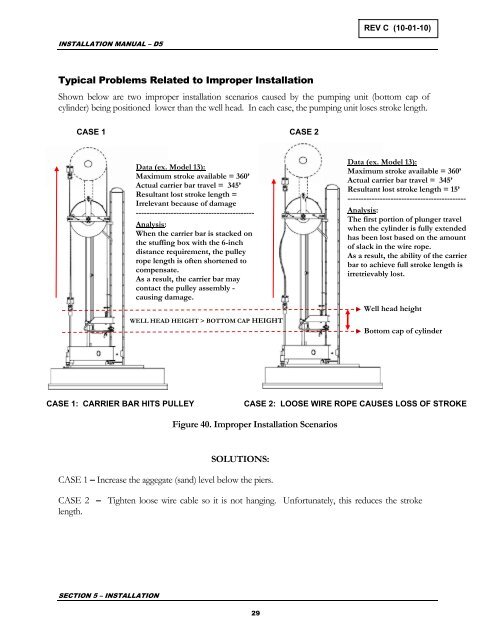
REV C (10-01-10)INSTALLATION MANUAL – D5Typical Problems Related to Improper <strong>Installation</strong>Shown below are two improper installation scenarios caused by the pumping unit (bottom cap ofcylinder) being positioned lower than the well head. In each case, the pumping unit loses stroke length.CASE 1CASE 2Data (ex. <strong>Model</strong> 13):Maximum stroke available = 360’Actual carrier bar travel = 345’Resultant lost stroke length =Irrelevant because of damage--------------------------------------------Analysis:When the carrier bar is stacked onthe stuffing box with the 6-inchdistance requirement, the pulleyrope length is often shortened tocompensate.As a result, the carrier bar maycontact the pulley assembly -causing damage.WELL HEAD HEIGHT > BOTTOM CAP HEIGHTData (ex. <strong>Model</strong> 13):Maximum stroke available = 360’Actual carrier bar travel = 345’Resultant lost stroke length = 15’--------------------------------------------Analysis:The first portion of plunger travelwhen the cylinder is fully extendedhas been lost based on the amountof slack in the wire rope.As a result, the ability of the carrierbar to achieve full stroke length isirretrievably lost.Well head heightBottom cap of cylinderCASE 1: CARRIER BAR HITS PULLEYCASE 2: LOOSE WIRE ROPE CAUSES LOSS OF STROKEFigure 40. Improper <strong>Installation</strong> ScenariosSOLUTIONS:CASE 1 – Increase the aggegate (sand) level below the piers.CASE 2 – Tighten loose wire cable so it is not hanging. Unfortunately, this reduces the strokelength.SECTION 5 – INSTALLATION29


