

Installation Manual - Model 5 - Tundra Process Solutions Ltd.
Installation Manual - Model 5 - Tundra Process Solutions Ltd.
Installation Manual - Model 5 - Tundra Process Solutions Ltd.

You also want an ePaper? Increase the reach of your titles
YUMPU automatically turns print PDFs into web optimized ePapers that Google loves.
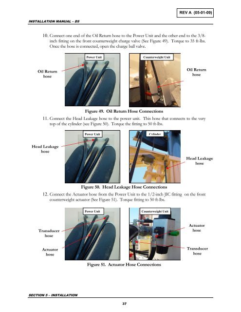
REV A (05-01-09)INSTALLATION MANUAL – D510. Connect one end of the Oil Return hose to the Power Unit and the other end to the 3/8-inch fitting on the front counterweight charge valve (See Figure 49). Torque to 35 ft-lbs.Once the hose is connected, open the charge ball valve.Power UnitCounterweight UnitOil ReturnhoseOil ReturnhoseFigure 49. Oil Return Hose Connections11. Connect the Head Leakage hose to the power unit. This hose that connects to the verytop of the cylinder (see Figure 50). Torque the fitting to 50 ft-lbs.Power UnitCylinderHead LeakagehoseHead LeakagehoseFigure 50. Head Leakage Hose Connections12. Connect the Actuator hose from the Power Unit to the 1/2-inch JIC fitting on the frontcounterweight actuator (See Figure 51). Torque fitting to 50 ft-lbs.Power UnitCounterweight UnitTransducerhoseActuatorhoseActuatorhoseTransducerhoseFigure 51. Actuator Hose ConnectionsSECTION 5 – INSTALLATION37


