

Installation Manual - Model 5 - Tundra Process Solutions Ltd.
Installation Manual - Model 5 - Tundra Process Solutions Ltd.
Installation Manual - Model 5 - Tundra Process Solutions Ltd.

Create successful ePaper yourself
Turn your PDF publications into a flip-book with our unique Google optimized e-Paper software.
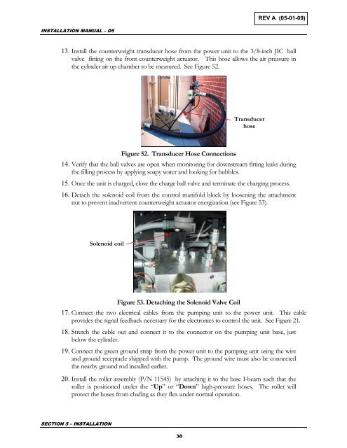
REV A (05-01-09)INSTALLATION MANUAL – D513. Install the counterweight transducer hose from the power unit to the 3/8-inch JIC ballvalve fitting on the front counterweight actuator. This hose allows the air pressure inthe cylinder air up chamber to be measured. See Figure 52.TransducerhoseFigure 52. Transducer Hose Connections14. Verify that the ball valves are open when monitoring for downstream fitting leaks duringthe filling process by applying soapy water and looking for bubbles.15. Once the unit is charged, close the charge ball valve and terminate the charging process.16. Detach the solenoid coil from the control manifold block by loosening the attachmentnut to prevent inadvertent counterweight actuator energization (see Figure 53).Solenoid coilFigure 53. Detaching the Solenoid Valve Coil17. Connect the two electrical cables from the pumping unit to the power unit. This cableprovides the signal feedback necessary for the electronics to control the unit. See Figure 21.18. Stretch the cable out and connect it to the connector on the pumping unit base, justbelow the cylinder.19. Connect the green ground strap from the power unit to the pumping unit using the wireand ground receptacle shipped with the pump. The ground wire must also be connectedthe nearby ground rod installed earlier.20. Install the roller assembly (P/N 11545) by attaching it to the base I-beam such that theroller is positioned under the “Up” or “Down” high-pressure hoses. The roller willprotect the hoses from chafing as they flex under normal operation.SECTION 5 – INSTALLATION38


