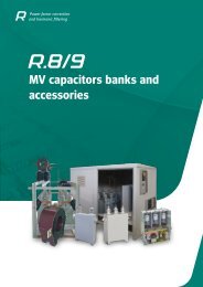
Automatic capacitor banks - Circutor
Automatic capacitor banks - Circutor
Automatic capacitor banks - Circutor

Create successful ePaper yourself
Turn your PDF publications into a flip-book with our unique Google optimized e-Paper software.
Power factor correction<br />
and harmonic filtering<br />
<strong>Automatic</strong> <strong>capacitor</strong> <strong>banks</strong>
<strong>Automatic</strong> <strong>capacitor</strong>s <strong>banks</strong><br />
ACF<br />
CS Capacitor with contactor and fuses· ·········································································· R3-4<br />
OPTIM 1<br />
Regulated <strong>capacitor</strong>s· ························································································ R3-6<br />
OPTIM<br />
<strong>Automatic</strong> <strong>capacitor</strong> <strong>banks</strong> ···················································································· R3-8<br />
R3-2
<strong>Automatic</strong> <strong>capacitor</strong> <strong>banks</strong><br />
<strong>Automatic</strong> <strong>capacitor</strong> <strong>banks</strong><br />
CIRCUTOR's range of <strong>capacitor</strong> <strong>banks</strong><br />
for contactor switching operations cover<br />
power levels 7.5 kvar to 1120 kvar (in<br />
the case of greater power levels, please<br />
ask).<br />
Initial data:<br />
Data that must be taken into account<br />
when selecting a <strong>capacitor</strong> bank:<br />
}}<br />
Total power factor consumption of the<br />
installation and cos φ objective.<br />
}}<br />
Voltage: the voltage of the unit must<br />
always be equal to or higher than the<br />
network voltage.<br />
}}<br />
Harmonic distortion levels<br />
}}<br />
Simultaneity of loads.<br />
}}<br />
Regulation of the <strong>capacitor</strong> bank: we<br />
recommend an approximate power of<br />
10% of the total power of the unit in the<br />
first step.<br />
Technical instruction ITC-BT-43 of the<br />
REBT, section 2.7 (Power factor correction)<br />
must be taken into account when<br />
selecting a <strong>capacitor</strong> bank:<br />
The installations that supply energy to<br />
receivers with a power factor under 1<br />
can be compensated. However, the energy<br />
absorbed by the network can not<br />
be capacitive.<br />
The Power factor correction process<br />
can be carried out as follows:<br />
►For ► each receiver or group of receivers<br />
operating at the same time and<br />
which are connected with a single<br />
switch. In this case the switch must<br />
cut off the power supply of the receiver<br />
or group of receivers and <strong>capacitor</strong><br />
at the same time.<br />
►For ► the whole installation. In this case,<br />
the compensation installation must be<br />
designed to make sure that the variation<br />
of the power factor does not automatically<br />
exceed ± 10% of the mean<br />
values obtained during a long period<br />
of operation.<br />
As a consequence, the installation can<br />
be compensated automatically at the<br />
header or individually.<br />
<strong>Automatic</strong> compensation at the<br />
header<br />
When selecting an automatic <strong>capacitor</strong><br />
bank, it is important to distinguish<br />
between the number of electrical steps<br />
and the number of physical steps.<br />
The number of physical steps is described<br />
by the number of contactor + <strong>capacitor</strong><br />
groups. In turn, electrical steps<br />
are defined by the different electrical<br />
R.3<br />
combinations of the unit. The number of<br />
electrical steps is the result of dividing<br />
the total power of the unit by the power<br />
of the lowest step. Here is an example.<br />
Example:<br />
440 kvar Capacitor bank<br />
Composition: (40 + 5x80) This <strong>capacitor</strong><br />
bank has 6 physical steps: One 40<br />
kvar step and five 80 kvar steps, and 11<br />
electrical steps: 11 x 40 kvar.<br />
From the point of view of efficiency, it is<br />
very important that the <strong>capacitor</strong> bank<br />
has enough electrical steps that can<br />
adapt to the demands of cos φ.<br />
A good balance between the physical<br />
and electrical regulation will allow us to<br />
fine tune the system at the lowest price.<br />
R3-3
<strong>Automatic</strong> <strong>capacitor</strong> <strong>banks</strong><br />
ACF<br />
CS Capacitor with contactor and fuses<br />
Description<br />
Features<br />
The fixed <strong>capacitor</strong>s of the ACF series are<br />
single-step units that have been designed<br />
for Power factor correction procedures under<br />
constant load.<br />
Application<br />
Its application is mainly focused on the compensation<br />
of motors, transformers and installations<br />
under constant load, providing a<br />
signal that connects to the <strong>capacitor</strong> with a<br />
contactor switching operation.<br />
Features<br />
Operating voltage<br />
Support voltage (400 V)<br />
230, 400 V (for other voltages, please ask)<br />
440 V<br />
Capacity tolerance ± 10%<br />
••<br />
CS <strong>capacitor</strong><br />
••<br />
Contactors with pre-insertion block<br />
Unit composed of<br />
and quick discharge resistor<br />
••<br />
Header protection with high rupture power (HRP)<br />
Insulation level<br />
Discharge resistance<br />
Overload<br />
Overvoltage<br />
Contactor operating voltage<br />
Ambient conditions<br />
Class D temperature<br />
Humidity<br />
Altitude<br />
Construction features<br />
Daily mean<br />
Annual mean<br />
Maximum<br />
Minimum<br />
3 / 15 kV<br />
75 V / 3 minutes<br />
1.3 times the rated current permanently<br />
••<br />
10% 8 over 24 hours<br />
••<br />
15% up to 15 minutes over 24 hours<br />
••<br />
20% up to 5 minutes over 24 hours<br />
••<br />
30% up to 1 minutes over 24 hours<br />
230 V<br />
45 ºC<br />
35 ºC<br />
50 ºC<br />
-25 ºC<br />
80% RH<br />
2,000 m<br />
Degree of protection IP 21<br />
Colour<br />
RAL 7035 Grey<br />
RAL 3005 Maroon<br />
Assembly conditions<br />
Type of assembly<br />
Vertical<br />
Ventilation<br />
Natural<br />
Standards<br />
CEI 60831-1, CEI 70/7, UNE 20827, UNE 20010, BS 1650, VDE 560<br />
R3-4
<strong>Automatic</strong> <strong>capacitor</strong> <strong>banks</strong><br />
ACF<br />
CS Capacitor with contactor and fuses<br />
Dimensions<br />
A (mm)<br />
ACF-50 324<br />
ACF-100 549<br />
References<br />
230 V<br />
kvar<br />
Cut off<br />
power<br />
(A)<br />
Fuses<br />
Cable section<br />
(mm 2 )<br />
Weight (kg)<br />
Dimensions (mm)<br />
width x height x depth<br />
20 120 kA 50 125 25 17 360 x 868 x 140 ACF-20-230 R3S141<br />
25 120 kA 63 125 35 21 360 x 1093 x 140 ACF-25-230 R3S151<br />
30 120 kA 75 160 50 22 360 x 1093 x 140 ACF-30-230 R3S161<br />
40 120 kA 100 160 70 27 360 x 1093 x 140 ACF-40-230 R3S181<br />
440 V<br />
kvar Cut off<br />
Cable section<br />
Dimensions (mm)<br />
(A)<br />
Fuses<br />
Weight (kg)<br />
440 400 power<br />
(mm 2 )<br />
width x height x depth<br />
Type<br />
Code<br />
12,5 10 120 kA 16 35 6 12 360 x 868 x 140 ACF-12.5-440 R3S421<br />
15 12,5 120 kA 20 35 10 13 360 x 868 x 140 ACF-15-440 R3S431<br />
20 17 120 kA 26 50 10 14 360 x 868 x 140 ACF-20-440 R3S441<br />
25 21 120 kA 33 63 10 15 360 x 868 x 140 ACF-25-440 R3S451<br />
30 25 120 kA 39 80 16 16 360 x 868 x 140 ACF-30-440 R3S461<br />
37,5 31 120 kA 49 80 25 17 360 x 868 x 140 ACF-37.5-440 R3S481<br />
50 42 120 kA 66 125 35 21 360 x 868 x 140 ACF-50-440 R3S491<br />
60 50 120 kA 79 160 50 22 360 x 1093 x 140 ACF-60-440 R3S4A1<br />
75 63 120 kA 99 160 70 24 360 x 1093 x 140 ACF-75-440 R3S4B1<br />
100 80 120 kA 131 160 70 29 360 x 1093 x 140 ACF-100-440 R3S4D1<br />
Type<br />
Code<br />
R3-5
<strong>Automatic</strong> <strong>capacitor</strong> <strong>banks</strong><br />
OPTIM 1<br />
Regulated <strong>capacitor</strong>s<br />
Description<br />
Features<br />
The regulated <strong>capacitor</strong>s of the OPTIM 1 /<br />
OPTIM 1A series are power factor compensation<br />
units operated by a computer one reactive<br />
relay.<br />
Application<br />
Their simple installation, high-technology and<br />
robustness make OPTIM 1 and OPTIM 1A<br />
regulated <strong>capacitor</strong>s an ideal compact unit for<br />
compensating reactive energy in low power<br />
installations or loads where the load levels<br />
are not subject to major fluctuations such as:<br />
}}<br />
Small businesses<br />
}}<br />
Restaurants<br />
}}<br />
Lifts<br />
}}<br />
Irrigation pumps<br />
}}<br />
etc.<br />
Electrical features<br />
Operating voltage<br />
400 V (other voltages: please ask)<br />
Support voltage<br />
440 V<br />
Frequency<br />
50 Hz (other voltages: please ask)<br />
Capacity tolerance -5%...+10%<br />
Insulation level<br />
3 kV at 50 Hz<br />
Impulse test 15 kV, ray type wave 1.2/50 µs<br />
Current transformer input<br />
250 mA<br />
Contactor operating voltage<br />
230 V<br />
••<br />
CLZ <strong>capacitor</strong>s<br />
Unit composed of<br />
••<br />
Appropriate contactors for capacitive currents<br />
••<br />
Circuit breaker protection<br />
••<br />
Computer One reactive relay<br />
Residual discharge voltage<br />
75 V / 3 minutes<br />
Total losses<br />
< 0.5 W / kvar<br />
••<br />
10% 8 over 24 hours<br />
Overvoltage<br />
••<br />
15% up to 15 minutes over 24 hours<br />
••<br />
20% up to 5 minutes over 24 hours<br />
••<br />
30% up to 1 minute over 24 hours<br />
Environmental conditions<br />
Class<br />
Temperature<br />
Humidity<br />
Altitude<br />
Daily mean<br />
Annual mean<br />
Maximum<br />
Minimum<br />
D according to IEC-60831<br />
45 ºC<br />
35 ºC<br />
55 ºC<br />
-25 ºC<br />
80% non-condensing<br />
< 1000 m above sea level.<br />
Mechanical features<br />
Enclosure material<br />
Thermoplastic<br />
Protection Degree IP 21<br />
Colour<br />
RAL 7035 Grey<br />
Assembly conditions<br />
Type of assembly<br />
Wall-mounted<br />
Position<br />
Vertical<br />
Ventilation<br />
Natural or forced, in accordance with options<br />
Standards<br />
IEC 60831-1, UNE 60831-1, IEC 61921, IEC 60439, IEC 61439<br />
R3-6
<strong>Automatic</strong> <strong>capacitor</strong> <strong>banks</strong><br />
OPTIM 1<br />
Regulated <strong>capacitor</strong>s<br />
Dimensions<br />
OPTIM 1<br />
OPTIM 1A<br />
ENTRADA CABLES<br />
CABLE INPUT 270<br />
215 166<br />
ENTRADA CABLES<br />
CABLE INPUT<br />
166<br />
500<br />
500<br />
140<br />
140<br />
References<br />
kvar<br />
Cable crosssection<br />
(mm 2 )<br />
width x height x depth<br />
Dimensions (mm)<br />
Switch<br />
Weight (kg)<br />
440 V 400 V<br />
Type<br />
Code<br />
2.5 2 Included 6 4 215 x 500 x 140 OPTIM 1-2.5-440 R3Q631EN<br />
5 4 Included 6 4.5 215 x 500 x 140 OPTIM 1-5-440 R3Q641EN<br />
6.25 5 Included 6 5 215 x 500 x 140 OPTIM 1-6.25-440 R3Q651EN<br />
10 8 Included 6 5 215 x 500 x 140 OPTIM 1-10-440 R3Q671EN<br />
12.5 10 Included 6 5 215 x 500 x 140 OPTIM 1-12.5-440 R3Q681EN<br />
15 12.5 Included 6 5 215 x 500 x 140 OPTIM 1-15-440 R3Q691EN<br />
18.2 15 Included 6 6 270 x 500 x 140 OPTIM 1A-18.2-440 R3Q6E1EN<br />
25 20 Included 10 7 270 x 500 x 140 OPTIM 1A-25-440 R3Q6F1EN<br />
30 25 Included 10 7 270 x 500 x 140 OPTIM 1A-30-440 R3Q6D1EN<br />
R3-7
<strong>Automatic</strong> <strong>capacitor</strong> <strong>banks</strong><br />
OPTIM<br />
<strong>Automatic</strong> <strong>capacitor</strong> <strong>banks</strong><br />
Description<br />
The OPTIM series automatic <strong>capacitor</strong><br />
<strong>banks</strong> have been designed for the automatic<br />
compensation of reactive energy in<br />
networks with fluctuating loads and power<br />
variations during seconds, by switching<br />
operations carried out by contactors.<br />
Application<br />
Their simple installation, high-technology<br />
and robustness make the OPTIM series the<br />
ideal unit for compensating reactive energy<br />
in installations with fluctuating load levels.<br />
Features<br />
Electrical features<br />
Operating voltage<br />
Support voltage<br />
Frequency<br />
400 V (please ask about<br />
other voltages)<br />
440 V<br />
Capacity tolerance -5%, +10%<br />
50 Hz (please ask about<br />
other frequencies)<br />
Impulse test 15 kV, ray type wave 1.2 / 50µs<br />
Current transformer<br />
input<br />
Contactor operating voltage<br />
Unit composed of<br />
••<br />
250 mA in OPTIM 2 model<br />
••<br />
5 A in OPTIM 3, OPTIM 3A, OPTIM 4,<br />
OPTIM 6, OPTIM 8, OPTIM SC8, OPTIM<br />
SC12 and OPTIM SC16 models<br />
CAPACITORS:<br />
230 V<br />
••<br />
CLZ type <strong>capacitor</strong> in OPTIM 2, OPTIM<br />
6, OPTIM 12 and OPTIM 8 models<br />
••<br />
CEUB type <strong>capacitor</strong> in OPTIM 3,<br />
OPTIM 3A and OPTIM 4 models<br />
••<br />
CSB type <strong>capacitor</strong> in OPTIM SC8, OPTIM<br />
SC12 and OPTIM SC16 models<br />
••<br />
Appropriate contactors for capacitive currents<br />
Protection:<br />
••<br />
Circuit breaker protection incorporated in<br />
OPTIM 2, OPTIM 3 and OPTIM 3A models<br />
••<br />
Fuses with high cut off power (APR): NH-<br />
00 type in OPTIM 4, OPTIM 6, OPTIM<br />
12, OPTIM 8, OPTIM SC8, OPTIM<br />
SC12 and OPTIM SC16 models<br />
POWER factor regULATOR:<br />
••<br />
Computer TWO, with 2 relay<br />
outputs, in OPTIM 2 model<br />
••<br />
Computer MAX with digital indication and 6<br />
or 12 relay outputs in accordance with type, in<br />
OPTIM 3, OPTIM 4, OPTIM 6, OPTIM 8, OPTIM<br />
SC8, OPTIM SC12 and OPTIM SC16 models<br />
••<br />
Manual <strong>capacitor</strong> bank header switch<br />
••<br />
Bank header circuit breaker<br />
••<br />
Bank header circuit breaker +<br />
earth leakage protection<br />
••<br />
Forced ventilation unit + thermostat<br />
••<br />
Polycarbonate sheet to protect<br />
Add-ons (optional)<br />
against direct contacts<br />
••<br />
400/230 V autotransformer<br />
••<br />
Computer SMART regulator with built-in<br />
power analyzer and single-phase measuring<br />
••<br />
Computer PLUS regulator with built-in power<br />
analyzer and three-phase measuring<br />
Residual discharge voltage<br />
75 V / 3 minutes<br />
Capacitor losses<br />
< 0.5 W / kvar<br />
Overload<br />
1.3 times the nominal hold current<br />
Overvoltage<br />
10% 8 over 24 hours<br />
15% up to 15 minutes<br />
over 24 hours<br />
20% up to 5 minutes<br />
over 24 hours<br />
30% up to 1 minute<br />
over 24 hours<br />
Class D according to IEC-60831:<br />
Daily mean: 45 ºC<br />
Temperature<br />
Annual mean: 35 ºC<br />
Maximum: 55 ºC<br />
Minimum: -50 ºC<br />
Environmental conditions<br />
Humidity<br />
80% non-condensing<br />
Altitude<br />
<strong>Automatic</strong> <strong>capacitor</strong> <strong>banks</strong><br />
OPTIM<br />
<strong>Automatic</strong> <strong>capacitor</strong> <strong>banks</strong><br />
References<br />
kvar<br />
440 V 400 V<br />
Composition<br />
Switch (A)<br />
Cable crosssection<br />
(mm 2 )<br />
Weight<br />
(kg)<br />
Dimensions (mm)<br />
width x height x depth<br />
Type<br />
Code<br />
7.5 6.25 2.5 + 5 Included 6 7 362 x 500 x 166 OPTIM 2-7.5-440 R3Q761EN<br />
10.5 8.5 3 + 7.5 Included 6 7 362 x 500 x 166 OPTIM 2-10.5-440 R3Q771EN<br />
12.5 10 5 + 7.5 Included 6 7 362 x 500 x 166 OPTIM 2-12.5-440 R3Q781EN<br />
17.5 14 5 + 12.5 Included 6 7 362 x 500 x 166 OPTIM 2-17.5-440 R3Q7E1EN<br />
20 16.5 7.5 + 12.5 Included 6 7 362 x 500 x 166 OPTIM 2-20-440 R3Q7F1EN<br />
22.5 18.5 7.5 + 15 Included 6 7 362 x 500 x 166 OPTIM 2-22.5-440 R3Q7G1EN<br />
25 21 10 + 15 Included 10 8 362 x 500 x 166 OPTIM 2-25-440 R3Q7H1EN<br />
30 25 15 + 15 Included 10 8 362 x 500 x 166 OPTIM 2-30-440 R3Q7J1EN<br />
7.5 6.2 2.5+5 Included 6 28 290 x 464 x 170 OPTIM 3-7.5-440 R3J105<br />
12.5 10 2.5+5+5 Included 6 28 290 x 464 x 170 OPTIM 3-12.5-440 R3J110<br />
17.5 14 2.5+5+10 Included 6 30 290 x 464 x 170 OPTIM 3-17.5-440 R3J115<br />
25 20 5+10+10 Included 10 31 290 x 464 x 170 OPTIM 3-25-440 R3J120<br />
31.25 26 6.25+12.5+12.5 Included 10 32 290 x 464 x 170 OPTIM 3-31.25-440 R3J130<br />
37.5 31.25 7.5+15+15 Included 16 33 335 x 560 x 170 OPTIM 3A-37.5-440 R3J135<br />
43.75 36 6.25+12.5+25 Included 25 36 335 x 560 x 170 OPTIM 3A-43.75-440 R3J140<br />
50 41 10+20+20 Included 25 37 335 x 560 x 170 OPTIM 3A-50-440 R3J145<br />
62.5 51 12.5+25+25 Included 35 40 335 x 560 x 170 OPTIM 3A-62.5-440 R3J150<br />
52.5 43 7.5+15+30 125 35 40 460 x 930 x 230 OPTIM 4-52.5-440 R3J204<br />
55 45 5+10+20+20 125 35 40 460 x 930 x 230 OPTIM 4-55-440 R3J205<br />
70 58 10+3x20 125 50 41 460 x 930 x 230 OPTIM 4-70-440 R3J210<br />
75 62 15+30+30 200 70 42 460 x 930 x 230 OPTIM 4-75-440 R3J220<br />
90 74 15+15+30+30 200 70 43 460 x 930 x 230 OPTIM 4-90-440 R3J230<br />
105 87 15+30+30+30 200 70 46 460 x 930 x 230 OPTIM 4-105-440 R3J240<br />
120 99 4x30 250 95 48 460 x 930 x 230 OPTIM 4-120-440 R3J250<br />
135 112 15+4x30 250 95 81 615 x 1330 x 400 OPTIM 6-135-440 R3J320<br />
150 124 5x30 400 120 82 615 x 1330 x 400 OPTIM 6-150-440 R3J330<br />
165 136 15+5x30 400 120 83 615 x 1330 x 400 OPTIM 6-165-440 R3J340<br />
180 149 6x30 400 150 87 615 x 1330 x 400 OPTIM 6-180-440 R3J350<br />
195 161 15+6x30 400 150 117 1180 x 1340 x 360 OPTIM 12-195-440 R3J520<br />
210 173 7x30 400 185 119 1180 x 1340 x 360 OPTIM 12-210-440 R3J530<br />
225 186 15+7x30 400 185 121 1180 x 1340 x 360 OPTIM 12-225-440 R3J540<br />
240 198 8x30 630 185 124 1180 x 1340 x 360 OPTIM 12-240-440 R3J545<br />
255 210 15+8x30 630 240 127 1180 x 1340 x 360 OPTIM 12-255-440 R3J550<br />
270 223 9x30 630 240 130 1180 x 1340 x 360 OPTIM 12-270-440 R3J560<br />
285 235 15+9x30 630 240 133 1180 x 1340 x 360 OPTIM 12-285-440 R3J565<br />
300 248 10x30 630 240 136 1180 x 1340 x 360 OPTIM 12-300-440 R3J570<br />
315 260 15+10x30 630 240 139 1180 x 1340 x 360 OPTIM 12-315-440 R3J575<br />
330 273 11x30 630 2x150 142 1180 x 1340 x 360 OPTIM 12-330-440 R3J580<br />
345 285 15+11x30 630 2x150 145 1180 x 1340 x 360 OPTIM 12-345-440 R3J585<br />
360 298 12x30 630 2x150 155 1180 x 1340 x 360 OPTIM 12-360-440 R3J590<br />
330 273 30+5x60 630 2x150 232 1180 x 1650 x 360 OPTIM 8-330-440 R3J405<br />
360 298 6x60 630 2x185 240 1180 x 1650 x 360 OPTIM 8-360-440 R3J410<br />
390 322 30+6x60 800 2x185 245 1180 x 1650 x 360 OPTIM 8-390-440 R3J420<br />
420 347 7x60 800 2x240 250 1180 x 1650 x 360 OPTIM 8-420-440 R3J430<br />
450 372 30+7x60 800 2x240 255 1180 x 1650 x 360 OPTIM 8-450-440 R3J440<br />
480 397 8x60 1000 2x240 260 1180 x 1650 x 360 OPTIM 8-480-440 R3J445<br />
450 372 50+4x100 800 2x185 270 1180 x 1805 x 460 OPTIM SC8-450-440 R3J640<br />
500 413 5x100 1000 2x240 275 1180 x 1805 x 460 OPTIM SC8-500-440 R3J650<br />
550 454 50+5x100 1000 2x240 280 1180 x 1805 x 460 OPTIM SC8-550-440 R3J655<br />
600 496 6x100 1250 2x240 285 1180 x 1805 x 460 OPTIM SC8-600-440 R3J660<br />
650 537 50+6x100 1250 3x150 290 1180 x 1805 x 460 OPTIM SC8-650-440 R3J665<br />
700 579 7x100 1250 3x150 295 1180 x 1805 x 460 OPTIM SC8-700-440 R3J670<br />
750 620 50+7x100 1600 3x185 300 1180 x 1805 x 460 OPTIM SC8-750-440 R3J675<br />
800 661 8x100 1600 3x185 305 1180 x 1805 x 460 OPTIM SC8-800-440 R3J680<br />
Switch and cable section for installations with U n<br />
= 400 V. The installation company must ensure compliance with the low<br />
voltage directive at all times, in accordance with the particularities of each installation and type of cable.<br />
R3-9
<strong>Automatic</strong> <strong>capacitor</strong> <strong>banks</strong><br />
OPTIM<br />
<strong>Automatic</strong> <strong>capacitor</strong> <strong>banks</strong><br />
References<br />
kvar<br />
440 V 400 V<br />
Composition<br />
Switch (A)<br />
Cable crosssection<br />
(mm 2 )<br />
Weight<br />
(kg)<br />
Dimensions (mm)<br />
width x height x depth<br />
900 744 9x100 1250 / 400 3x150 / 185 525 1930 x 1805 x 460 OPTIM SC12-900-440 R3J765<br />
950 785 50+9x100 1600 / 400 3x185 / 185 535 1930 x 1805 x 460 OPTIM SC12-950-440 R3J770<br />
1000 826 10x100 1600 / 400 3x185 / 185 545 1930 x 1805 x 460 OPTIM SC12-1000-440 R3J775<br />
1050 868 50+10x100 1600 / 630 3x185 / 240 555 1930 x 1805 x 460 OPTIM SC12-1050-440 R3J780<br />
1100 909 11x100 1600 / 630 3x185 / 2x120 565 1930 x 1805 x 460 OPTIM SC12-1100-440 R3J785<br />
1150 950 50+11x100 1600 / 800 3x185 / 2x150 575 1930 x 1805 x 460 OPTIM SC12-1150-440 R3J790<br />
1200 992 12x100 1600 / 800 3x185 / 2x185 585 1930 x 1805 x 460 OPTIM SC12-1200-440 R3J795<br />
1300 1074 100+6x200 1250 / 1250 3x185 / 2x240 590 2460 x 1805 x 460 OPTIM SC16-1300-440 R3J880<br />
1400 1157 100+100+6x200 1600 / 1250 3x185 / 3x120 595 2460 x 1805 x 460 OPTIM SC16-1400-440 R3J885<br />
1500 1240 100+7x200 1600 / 1600 3x185 / 3x150 600 2460 x 1805 x 460 OPTIM SC16-1500-440 R3J890<br />
1600 1322 100+100+7x200 1600 / 1600 3x185 / 3x185 605 2460 x 1805 x 460 OPTIM SC16-1600-440 R3J895<br />
Switch and cable section for installations with U n<br />
= 400 V. The installation company must ensure compliance with the low<br />
voltage directive at all times, in accordance with the particularities of each installation and type of cable.<br />
Type<br />
Code<br />
Dimensions<br />
OPTIM 2<br />
362<br />
166<br />
OPTIM 3<br />
500<br />
140<br />
OPTIM 3A<br />
335 170<br />
OPTIM 4<br />
560<br />
405<br />
345<br />
R3-10
<strong>Automatic</strong> <strong>capacitor</strong> <strong>banks</strong><br />
OPTIM<br />
<strong>Automatic</strong> <strong>capacitor</strong> <strong>banks</strong><br />
Dimensions<br />
OPTIM 6<br />
OPTIM 8<br />
1650<br />
1550<br />
100<br />
1180 360<br />
OPTIM SC8<br />
1 180<br />
OPTIM 12<br />
1805<br />
1340<br />
1240<br />
100<br />
1180 360<br />
460<br />
R3-11
<strong>Automatic</strong> <strong>capacitor</strong> <strong>banks</strong>, LV<br />
Designed by: Comunication & image dpt of CIRCUTOR, SA<br />
+ information: central@circutor.es<br />
www.circutor.com<br />
CIRCUTOR, SA - Vial Sant Jordi, s/n<br />
08232 Viladecavalls (Barcelona) España<br />
Tel. (+34) 93 745 29 00 - Fax: (+34) 93 745 29 14<br />
central@circutor.es<br />
CIRCUTOR, SA reserves the right to change any of the information contained in this catalogue.