MRI Artifacts: Mechanism and Control
MRI Artifacts: Mechanism and Control
MRI Artifacts: Mechanism and Control

Create successful ePaper yourself
Turn your PDF publications into a flip-book with our unique Google optimized e-Paper software.
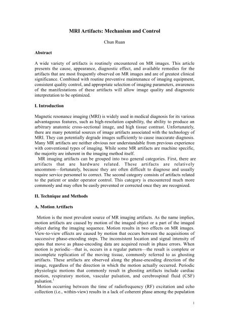
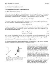
<strong>MRI</strong> <strong>Artifacts</strong>: <strong>Mechanism</strong> <strong>and</strong> <strong>Control</strong><br />
Chun Ruan<br />
Abstract<br />
A wide variety of artifacts is routinely encountered on MR images. This article<br />
presents the cause, appearance, diagnostic effect, <strong>and</strong> available remedies for the<br />
artifacts that are most frequently observed on MR images <strong>and</strong> are of greatest clinical<br />
significance. Combined with routine preventive maintenance of imaging equipment,<br />
consistent quality control, <strong>and</strong> appropriate selection of imaging parameters, awareness<br />
of the manifestations of these artifacts will allow image quality <strong>and</strong> diagnostic<br />
interpretation to be optimized.<br />
I. Introduction<br />
Magnetic resonance imaging (<strong>MRI</strong>) is widely used in medical diagnosis for its various<br />
advantageous features, such as high-resolution capability, the ability to produce an<br />
arbitrary anatomic cross-sectional image, <strong>and</strong> high tissue contrast. Unfortunately,<br />
there are many potential sources of image artifacts associated with the technology of<br />
<strong>MRI</strong>. They can potentially degrade images sufficiently to cause inaccurate diagnosis.<br />
Many MR artifacts are neither obvious nor underst<strong>and</strong>able from previous experience<br />
with conventional types of imaging. While some MR artifacts are machine specific,<br />
the majority are inherent in the imaging method itself.<br />
MR imaging artifacts can be grouped into two general categories. First, there are<br />
artifacts that are hardware related. These artifacts are relatively<br />
uncommon—fortunately, because they are often difficult to diagnose <strong>and</strong> usually<br />
require service personnel to correct. The second category consists of artifacts related<br />
to the patient or under operator control. This category is encountered much more<br />
commonly <strong>and</strong> may often be easily prevented or corrected once they are recognized.<br />
II. Technique <strong>and</strong> Methods<br />
A. Motion <strong>Artifacts</strong><br />
Motion is the most prevalent source of MR imaging artifacts. As the name implies,<br />
motion artifacts are caused by motion of the imaged object or a part of the imaged<br />
object during the imaging sequence. Motion results in two effects on MR images.<br />
View-to-view effects are caused by motion that occurs between the acquisitions of<br />
successive phase-encoding steps. The inconsistent location <strong>and</strong> signal intensity of<br />
spins that move as phase-encoding data are acquired result in phase errors. When<br />
motion is periodic—that is, occurs in a regular pattern—the result is complete or<br />
incomplete replication of the moving tissue, commonly referred to as ghosting<br />
artifacts. These artifacts are observed along the phase-encoding direction of the<br />
image, regardless of the direction in which the motion actually occurred. Periodic<br />
physiologic motions that commonly result in ghosting artifacts include cardiac<br />
motion, respiratory motion, vascular pulsation, <strong>and</strong> cerebrospinal fluid (CSF)<br />
pulsation. 1<br />
Motion occurring between the time of radiofrequency (RF) excitation <strong>and</strong> echo<br />
collection (i.e., within-view) results in a lack of coherent phase among the population<br />
1
of moving spins at the time of echo formation. 2 This incoherence manifests as<br />
blurring <strong>and</strong> increased image noise. Unlike phase errors encountered in view-to-view<br />
motion effects, this within-view effect is expressed throughout the image. It is most<br />
frequently associated with r<strong>and</strong>om motion, as can occur with gastrointestinal<br />
peristalsis, swallowing, coughing, eye motion, <strong>and</strong> gross patient movement. 3<br />
1. Respiratory motion<br />
Respiratory motion results in ghosting artifacts <strong>and</strong> blurring that can obscure or<br />
simulate lesions. A variety of methods have been used to reduce the effect of<br />
respiratory motion artifacts. Mechanical methods, such as use of an abdominal or<br />
thoracic binder or taking images with the patient in a prone position, are intended to<br />
restrict the amplitude of respiratory motion. However, these maneuvers often produce<br />
patient discomfort <strong>and</strong> may therefore have counterproductive effects; Signal<br />
averaging is the use of multiple data acquisitions to improve the signal-to-noise ratio<br />
(SNR) of the image ( Fig.1). In this process, the prominence of ghosting artifacts is<br />
reduced by approximately the square root of the number of signal averages obtained.<br />
Of course, imaging time increases linearly with the number of signal averages; With<br />
respiratory triggering, data are collected only during a limited portion of the<br />
respiratory cycle, usually near end-expiration, when respiratory movement is minimal.<br />
The major drawback of this technique is its marked prolongation of imaging time,<br />
because so much of the time is not being used productively for data acquisition;<br />
Respiratory ordered phase encoding involves monitoring the patient’s respiratory<br />
cycle during imaging using a bellows device. Unlike respiratory triggering, however,<br />
with this method data are collected in a continuous fashion. This method does not<br />
restrict the operator’s selection of TR, <strong>and</strong> it does not significantly extend imaging<br />
time; Gradient moment nulling involves the application of additional gradient pulses<br />
to correct for phase shifts among a population of moving protons at the time of echo<br />
collection. This method corrects for constant-velocity motion <strong>and</strong> helps reduce the<br />
signal loss <strong>and</strong> ghosting associated with such movement. Use of gradient moment<br />
nulling requires a nominal TE, which may preclude its use on T1-weighted pulse<br />
sequences. This method does not prolong image acquisition time; Another method to<br />
reducing the signal intensity of moving tissue is the use of fat suppression methods.<br />
With this method, not only subcutaneous fat but also mediastinal, mesenteric,<br />
retroperitoneal, <strong>and</strong> other stores of internal fat are suppressed <strong>and</strong> are thus less<br />
capable of generating ghosting artifacts.<br />
2
2. Cardiac motion<br />
Figure 1. The image on the left exhibits respiratory motion as blurring of the structures<br />
as well as motion-induced ghosting. By using multiple averages motion can be reduced in<br />
the same way that multiple averages increase the signal to noise ratio. The image on the<br />
right was obtained with 16 averages.<br />
Cardiac motion produces a series of ghost artifacts along the phase-encoding<br />
direction of the image, in addition to blurring <strong>and</strong> signal loss of cardiac <strong>and</strong><br />
juxtacardiac structures. 4 The major approach for reducing cardiac motion artifacts is<br />
electrocardiographic triggering, in which data collection is synchronized with cardiac<br />
phase ( Fig. 2). This synchronization enables cardiac tissue to be located in a<br />
consistent position as each successive phase-encoding step is acquired, resulting in<br />
increased tissue signal intensity <strong>and</strong> decreased phase errors. Other approaches include<br />
the use of fast imaging sequences that reduce the opportunity for motion during data<br />
acquisition, gradient moment nulling, <strong>and</strong> spatial RF presaturation pulses.<br />
3. Vascular Pulsation<br />
Figure 2. The image on the left was acquired without any form of motion compensation<br />
technique for cardiac motion. The image on the right was obtained using cardiac gating.<br />
Vascular pulsation artifacts are recognized by their alignment with the responsible<br />
vessel along the phase-encoding direction of the image. These artifacts reproduce the<br />
cross-sectional size <strong>and</strong> shape of the responsible vessel, but not necessarily its signal<br />
intensity. Spatial RF presaturation pulses applied outside the field of view help reduce<br />
the signal intensity of inflowing blood <strong>and</strong>, hence reduce the resultant pulsation<br />
artifact. Other practical methods for reducing the prominence of vascular pulsation<br />
artifacts include positioning the section of interest in the middle of a multisection<br />
acquisition, thus reducing any potential entry phenomenon, <strong>and</strong> maximizing the<br />
saturation of flowing spins.<br />
B. Susceptibility <strong>Artifacts</strong><br />
Susceptibility artifacts occur as the result of microscopic gradients or variations in<br />
the magnetic field strength that occurs near the interfaces of substance of different<br />
magnetic susceptibility ( Fig. 3). Large susceptibility artifacts are commonly seen<br />
surrounding ferromagnetic objects inside of diamagnetic materials (such as the human<br />
body). These gradients cause dephasing of spins <strong>and</strong> frequency shifts of the<br />
surrounding tissues. The net results are bright <strong>and</strong> dark areas with spatial distortion of<br />
surrounding anatomy. These artifacts are worst with long echo times <strong>and</strong> with<br />
3
gradient echo sequences.<br />
Susceptibility artifacts can be made less prominent by performing imaging at low<br />
magnetic field strength, using smaller voxels, decreasing echo time, <strong>and</strong> increasing<br />
receiver b<strong>and</strong>width. Gradient-echo <strong>and</strong> echo-planar sequences should be avoided,<br />
because they accentuate susceptibility artifacts. The use of spin-echo <strong>and</strong> particularly<br />
fast spin-echo sequences should be considered.<br />
C. Chemical Shift <strong>Artifacts</strong><br />
Figure 3. An axial <strong>MRI</strong> of the head in a patient with mascara on her eyelids.<br />
Susceptibility artifacts from the mascara obscure the front half of the<br />
globes.<br />
A chemical shift artifact is caused by the difference in chemical shift (Larmor<br />
frequency) of fat <strong>and</strong> water. The artifact manifests itself as a misregistration between<br />
the fat <strong>and</strong> water pixels in an image ( Fig. 4). The effect being that fat <strong>and</strong> water spins<br />
in the same voxel are encoded as being located in different voxels. The magnitude of<br />
the effect is proportional on the magnitude of the Bo field <strong>and</strong> inversely proportional<br />
to the sampling rate in the frequency encoding direction. For a constant sampling rate,<br />
the larger Bo, the greater the effect. 5 Chemical shift artifacts are typically observed<br />
along the frequency-encoding direction but can also occur along the slice-selection<br />
direction of the image.<br />
Chemical shift artifact can be reduced by performing imaging at low magnetic field<br />
strength, by increasing receiver b<strong>and</strong>width, or by decreasing voxel size. The artifacts<br />
tend to be more prominent on T2-weighted than on T1-weighted images. Fat<br />
suppression methods often eliminate visible artifacts, <strong>and</strong> gradient reorientation can<br />
redirect chemical shift artifacts to another portion of the image.<br />
4
D. Wrap Around <strong>Artifacts</strong><br />
Figure 4. This artifact is shown in an axial image of a kidney where the<br />
bright border along the top of the kidney <strong>and</strong> the dark border along the<br />
bottom of the kidney represent the artifact.<br />
A wrap around artifact is the occurrence of a part of the imaged anatomy, which is<br />
located outside of the field of view, inside of the field of view ( Fig. 5). This artifact is<br />
caused by the selected field of view being smaller than the size of the imaged object.<br />
Or more specifically the digitization rate is less than the range of frequencies in the<br />
FID or echo. 6 The solution to a wrap around artifact is to choose a larger field of<br />
view, adjust the position of the image center, or select an imaging coil which will not<br />
excite or detect spins from tissues outside of the desired field of view.<br />
Figure 5. The first image shows wrap-around of the back of the head on to the front of the<br />
head, where the phase-encoded direction is anterior-posterior. The second image has the phase<br />
<strong>and</strong> frequency directions reversed resulting in absence of the aliasing artifact. Oversampling<br />
was used in the frequency direction to eliminate the aliasing.<br />
E. Partial Volume <strong>Artifacts</strong><br />
A partial volume artifact is any artifact which is caused by the size of the image<br />
voxel. It occurs when multiple tissue types are encompassed within a single voxel.<br />
For example, if a small voxel contains only fat or water signal, <strong>and</strong> a larger voxel<br />
might contain a combination of the two, the large voxel possess a signal intensity<br />
equal to the weighted average of the quantity of water <strong>and</strong> fat present in the voxel.<br />
Volume averaging is most likely to occur in the slice-selection direction of the image,<br />
which has the largest voxel dimension. It also occurs when structures are oriented<br />
obliquely to the imaging plane <strong>and</strong> when structures move in <strong>and</strong> out of a given section<br />
during image acquisition. Volume averaging can simulate abnormalities, decrease the<br />
visualization of low-contrast abnormalities, <strong>and</strong> blur or distort affected structures.<br />
Partial volumeaveraging is usually recognized by careful analysis of adjacent<br />
images. Decreasing voxel size, particularly reducing section thickness, can be useful<br />
if further confirmation is required ( Fig.6). Three-dimensional Fourier transform<br />
imaging is particularly useful, because it provides thin sections with no intervening<br />
gaps <strong>and</strong> is conductive to reformatting in alternate imaging planes; Simple acquisition<br />
of additional two-dimensional images in alternate imaging planes is very helpful for<br />
resolving issues relating to partial volume averaging. Retrospective reformatting of<br />
two-dimensional data can also be performed using an interpolation algorithm <strong>and</strong> can<br />
be of further assistance.<br />
5
Figur e 6. These two axial T1-weighted images of the head were obtained at exactly the same location,<br />
yet the second image shows the VII <strong>and</strong> VIII cranial nerves while the first does not. The reason<br />
for the vanishing nerve is explained by partial volume averaging. The first slice was obtained<br />
with a thickness of 10 mm while the second was at a thickness of 3 mm.<br />
F. Gibbs Ringing <strong>Artifacts</strong><br />
Gibbs ringing artifacts are bright or dark lines that are seen parallel <strong>and</strong> adjacent to<br />
borders of abrupt intensity change. The ringing is caused by incomplete digitization of<br />
the echo. This means the signal has not decayed to zero by the end of the acquisition<br />
window, <strong>and</strong> the echo is not fully digitized. This artifact is seen in images when a<br />
small acquisition matrix is used. Solutions include use of a higher resolution imaging<br />
matrix <strong>and</strong> filtration methods ( Fig.7). Gradient reorientation will displace the artifacts<br />
to another portion of the image.<br />
Figure 7. The fine lines visible in the image on the left are due to undersampling of the high spatial<br />
frequencies. This results in a "ringing" type of artifact following these borders in the phase direction (R<br />
to L in this image). This problem can be easily fixed by taking more samples such as the image on the<br />
right with 256 phase encodes.<br />
G. Zebra Stripes<br />
Zebra stripes can be observed along the periphery of gradient-echo images where<br />
there is an abrupt transition in magnetization at the air-tissue interface. They are<br />
accentuated by aliasing that results from the use of a relatively small field of view.<br />
Solutions include exp<strong>and</strong>ing the field of view, using spin-echo pulse sequences, or<br />
using oversampling techniques to reduce aliasing.<br />
H. Slice-overlap <strong>Artifacts</strong><br />
6
The slice-overlap artifact is the loss of signal seen in an image from a multi-angle,<br />
multi-slice acquisition, as is obtained commonly in the lumbar spine. If the slices<br />
obtained at different disk spaces are not parallel, then the slices may overlap. If two<br />
levels are done at the same time, e.g., L4-5 <strong>and</strong> L5-S1, then the level acquired second<br />
will include spins that have already been saturated. This causes a b<strong>and</strong> of signal loss<br />
crossing horizontally in image, usually worst posteriorly. Therefore, overlap of<br />
sections within areas of diagnostic interest should be carefully avoided.<br />
I. RF Overflow <strong>Artifacts</strong><br />
RF overflow artifacts cause a non-uniform, washed-out appearance to an image. This<br />
artifact occurs when the signal received by the scanner from the patient is too intense<br />
to be accurately digitized by the analog-to-digital converter. Autoprescanning usually<br />
adjusts the receiver gain to prevent this from occurring but if the artifact still occurs,<br />
the receiver gain can be decreased manually.<br />
J. Entry Slice Phenomenon<br />
Entry slice phenomenon occurs when unsaturated spins in blood first enter into a<br />
slice or slices. It is characterized by bright signal in a blood vessel (artery or vein) at<br />
the first slice that the vessel enters. Usually the signal is seen on more than one slice,<br />
fading with distance. This artifact has been confused with thrombosis with disastrous<br />
results. The characteristic location <strong>and</strong> if necessary, the use of gradient echo flow<br />
techniques can be used to differentiate entry slice artifacts from occlusions.<br />
K. Zipper <strong>Artifacts</strong><br />
There are various causes for zipper artifacts in images. Most of them are related to<br />
hardware or software problems beyond the physicist immediate control. The zipper<br />
artifacts that can be controlled easily are those due to RF entering the scanning room<br />
when the door is open during acquisition of images. 7 RF from some radio transmitters<br />
will cause zipper artifacts that are oriented perpendicular to the frequency axis of<br />
image. Broad-b<strong>and</strong> noise degrades the entire image, whereas narrow frequency noise<br />
produces linear b<strong>and</strong>s that transverse the phase-encoding direction of the image.<br />
Solutions include identifying <strong>and</strong> removing external RF sources, ensuring that the<br />
door to the imaging room remains closed, <strong>and</strong> verifying the integrity of the magnet<br />
room enclosure <strong>and</strong> associated seals.<br />
L. Cross-Excitation<br />
Cross-excitation is caused by the imperfect shape of RF slice profiles, which leads to<br />
the unintended excitation of adjacent tissue. This excitation results in the saturation of<br />
such tissue, manifest as decreased signal intensity <strong>and</strong> decreased contrast that can<br />
hinder lesion detection. One way to avoid this artifact is to introduce an intersection<br />
gap that is 10% to 50% of the prescribed section thickness. Another method is<br />
interleaved image acquisition, in which odd-numbered sections are initially acquired,<br />
followed by acquisition of even-numbered sections. 8 Also, optimized RF pulses that<br />
have a more rectangular slice profile can be implemented.<br />
7
Figure 8.The dark b<strong>and</strong>s visible on the T1-weighted Spin Echo axial image are due to the<br />
intersection of other axial images through the image. These are acquired in a multi-planar<br />
fashion <strong>and</strong> thus cause pre-excitation (saturation) of the protons in the area where the slices<br />
intersect. The sagittal image illustrates where the slices were obtained <strong>and</strong> how they intersect<br />
posteriorly.<br />
M. Shading<br />
Shading artifacts manifest as foci of relatively reduced signal intensity involving a<br />
portion of the image. Abnormalities contained in the shaded portion of the MR image<br />
may be obscured. 9 There are many potential causes for this artifact, including partial<br />
volume averaging malfunction of the RF transmitter, amplifier, or receiver, excessive<br />
RF absorption, etc. 10, 11 To minimize shading artifacts, the anatomy of interest should<br />
be centered within the magnet, within the coil, <strong>and</strong> within the group of sections to be<br />
acquired.<br />
III. Conclusions<br />
<strong>Artifacts</strong> are common in magnetic resonance imaging. Most occur as a result of<br />
interactions of multiple factors, especially motion. MR artifacts primarily cause image<br />
degradation, although they can occasionally mimic pathological lesions. Some MR<br />
artifacts, such as those caused by periodic respiratory or vascular motion, may<br />
obscure important diagnostic findings. These <strong>and</strong> other MR artifacts may be<br />
minimized in some instances by proper selection of the directions of the phase <strong>and</strong><br />
frequency encoding gradients. The ability to select <strong>and</strong> vary the direction of these<br />
gradients is a useful option in MR imaging. Investigations in the origins of <strong>MRI</strong><br />
artifacts can not only lead to further underst<strong>and</strong>ing of the imaging process itself, but<br />
can also improve the quality <strong>and</strong> diagnostic accuracy of MR examination.<br />
1 Saloner D, “Flow <strong>and</strong> motion,” Magn Reson Imaging Clin N Am 1999 Nov;7(4):699-715.<br />
2 Barish MA <strong>and</strong> Jara H, “Motion artifact control in body MR imaging,” Magn Reson Imaging Clin N<br />
Am 1999 May;7(2):289-301.<br />
3 Hedley M, Yan H, “ Motion artifact suppression: a review of post-processing techniques,” Magn<br />
Reson Imaging 1992;10(4):627-35.<br />
4 Huber ME, Hengesbach D <strong>and</strong> Botnar RM, “ Motion artifact reduction <strong>and</strong> vessel enhancement for<br />
free-breathing navigator-gated coronary MRA using 3D k-space reordering,” Magn Reson Med 2001<br />
Apr;45(4):645-52.<br />
5 Altbach MI, Trouard TP <strong>and</strong> Van<br />
de Walle R, “Chemical-shift imaging utilizing the positional shifts along the readout gradient<br />
direction,” IEEE Trans Med Imaging 2001 Nov;20(11):1156-66.<br />
6 Tsai CM <strong>and</strong> Nishimura DG, “<br />
Reduced aliasing artifacts using variable-density k-space sampling trajectories,” Magn Reson Med<br />
2000 Mar;43(3):452-8.<br />
7 Mugler JP 3rd, “Overview of MR imaging pulse<br />
sequences,” Magn Reson Imaging Clin N Am 1999 Nov;7(4):661-97.<br />
8
8 Clark JA 2nd <strong>and</strong> Kelly WM, “Common artifacts encountered in magnetic resonance imaging,” Radiol<br />
Clin North Am 1988 Sep;26(5):893-920.<br />
9 Jones RW <strong>and</strong> Witte RJ, “Signal intensity artifacts in clinical MR imaging,” Radiographics 2000 May-<br />
Jun;20(3):893-901.<br />
10 Mirowitz SA, “MR imaging artifacts.<br />
Challenges <strong>and</strong> solutions,” Magn Reson Imaging Clin N Am 1999 Nov;7(4):717-32.<br />
11 Mirowitz SA, “MR imaging artifacts. Challenges <strong>and</strong> solutions,” Magn Reson Imaging Clin N Am<br />
1999 Nov;7(4):717-32.<br />
9

![Methods for preventing Motion Artifacts in MRI [pdf]](https://img.yumpu.com/28806288/1/190x146/methods-for-preventing-motion-artifacts-in-mri-pdf.jpg?quality=85)