BreezeMAX IDU-DV Product Manual - Alvarion
BreezeMAX IDU-DV Product Manual - Alvarion
BreezeMAX IDU-DV Product Manual - Alvarion

Create successful ePaper yourself
Turn your PDF publications into a flip-book with our unique Google optimized e-Paper software.
<strong>BreezeMAX</strong> <strong>IDU</strong>-<strong>DV</strong><br />
<strong>Product</strong> <strong>Manual</strong><br />
SW Version R2L<br />
December 2008<br />
P/N 215077
Document History<br />
Document History<br />
Topic Description Date Issued<br />
3.5.1 Network Settings Added <strong>IDU</strong>-<strong>DV</strong> Identity and host name Version R2L<br />
June 2008<br />
3.7.1 SIP Configuration Page Added MS to HA Methods and POTs<br />
state indication<br />
Version R2L<br />
June 2008<br />
3.7.1.1 Codex and Fax<br />
Configuration<br />
Added configurable RFC2833 Payload<br />
Version R2L<br />
June 2008<br />
3.7.7 Line Test Added new feature Version R2L<br />
June 2008<br />
3.9.1 Security Removed Access Mode Version R2L<br />
June 2008<br />
3.9.6 CFG Upload Page Added feature Version R2L<br />
June 2008<br />
3.9.7 Ping Test Added feature Version R2L<br />
June 2008<br />
3.13 Parameters Summary Updated Version R2L<br />
June 2008<br />
1.3.1 Telephony and Fax<br />
Services<br />
3.7.1.1 Codecs and Fax<br />
Configuration<br />
Added Payphone<br />
Added RFC2833 Payload<br />
Version R2L<br />
September 2008<br />
Version R2L<br />
September 2008<br />
3.10 Upgrade Page Note added that software upgrade can<br />
only be done via the WAN port<br />
Version R2L<br />
September 2008<br />
3.13 Parameters Summary Parameters Summary table was updated Version R2L<br />
September 2008<br />
ii<br />
<strong>BreezeMAX</strong> <strong>IDU</strong>-<strong>DV</strong> <strong>Product</strong> <strong>Manual</strong>
Legal Rights<br />
Legal Rights<br />
Trade Names<br />
© Copyright 2008 <strong>Alvarion</strong> Ltd. All rights reserved.<br />
The material contained herein is proprietary, privileged, and confidential and<br />
owned by <strong>Alvarion</strong> or its third party licensors. No disclosure thereof shall be made<br />
to third parties without the express written permission of <strong>Alvarion</strong> Ltd.<br />
<strong>Alvarion</strong> Ltd. reserves the right to alter the equipment specifications and<br />
descriptions in this publication without prior notice. No part of this publication<br />
shall be deemed to be part of any contract or warranty unless specifically<br />
incorporated by reference into such contract or warranty.<br />
<strong>Alvarion</strong>®, BreezeCOM®, WALKair®, WALKnet®, BreezeNET®, BreezeACCESS®,<br />
BreezeLINK®, <strong>BreezeMAX</strong>®, BreezeLITE®, BreezePHONE®, 4Motion®,<br />
BreezeCONFIG, AlvariSTAR, AlvariCRAFT, MGW, eMGW and/or other<br />
products and/or services referenced here in are either registered trademarks,<br />
trademarks or service marks of <strong>Alvarion</strong> Ltd.<br />
All other names are or may be the trademarks of their respective owners.<br />
Statement of Conditions<br />
The information contained in this manual is subject to change without notice.<br />
<strong>Alvarion</strong> Ltd. shall not be liable for errors contained herein or for incidental or<br />
consequential damages in connection with the furnishing, performance, or use of<br />
this manual or equipment supplied with it.<br />
Warranties and Disclaimers<br />
Exclusive Warranty<br />
All <strong>Alvarion</strong> Ltd. ("<strong>Alvarion</strong>") products purchased from <strong>Alvarion</strong> or through any of<br />
<strong>Alvarion</strong>'s authorized resellers are subject to the following warranty and product<br />
liability terms and conditions.<br />
(a) <strong>Alvarion</strong> warrants that the <strong>Product</strong> hardware it supplies and the tangible<br />
media on which any software is installed, under normal use and conditions, will<br />
be free from significant defects in materials and workmanship for a period of<br />
fourteen (14) months from the date of shipment of a given <strong>Product</strong> to Purchaser<br />
(the "Warranty Period"). <strong>Alvarion</strong> will, at its sole option and as Purchaser's sole<br />
remedy, repair or replace any defective <strong>Product</strong> in accordance with <strong>Alvarion</strong>'<br />
standard R&R procedure.<br />
(b) With respect to the Firmware, <strong>Alvarion</strong> warrants the correct functionality<br />
according to the attached documentation, for a period of fourteen (14) month from<br />
invoice date (the "Warranty Period"). During the Warranty Period, <strong>Alvarion</strong> may<br />
<strong>BreezeMAX</strong> <strong>IDU</strong>-<strong>DV</strong> <strong>Product</strong> <strong>Manual</strong><br />
iii
Legal Rights<br />
Disclaimer<br />
release to its Customers firmware updates, which include additional performance<br />
improvements and/or bug fixes, upon availability (the "Warranty"). Bug fixes,<br />
temporary patches and/or workarounds may be supplied as Firmware updates.<br />
Additional hardware, if required, to install or use Firmware updates must be<br />
purchased by the Customer. <strong>Alvarion</strong> will be obligated to support solely the two (2)<br />
most recent Software major releases.<br />
ALVARION SHALL NOT BE LIABLE UNDER THIS WARRANTY IF ITS TESTING<br />
AND EXAMINATION DISCLOSE THAT THE ALLEGED DEFECT IN THE PRODUCT<br />
DOES NOT EXIST OR WAS CAUSED BY PURCHASER'S OR ANY THIRD<br />
PERSON'S MISUSE, NEGLIGENCE, IMPROPER INSTALLATION OR IMPROPER<br />
TESTING, UNAUTHORIZED ATTEMPTS TO REPAIR, OR ANY OTHER CAUSE<br />
BEYOND THE RANGE OF THE INTENDED USE, OR BY ACCIDENT, FIRE,<br />
LIGHTNING OR OTHER HAZARD.<br />
(a) The <strong>Product</strong> is sold on an "AS IS" basis. <strong>Alvarion</strong>, its affiliates or its licensors<br />
MAKE NO WARRANTIES, WHATSOEVER, WHETHER EXPRESS OR IMPLIED,<br />
WITH RESPECT TO THE SOFTWARE AND THE ACCOMPANYING<br />
DOCUMENTATION. ALVARION SPECIFICALLY DISCLAIMS ALL IMPLIED<br />
WARRANTIES OF MERCHANTABILITY AND FITNESS FOR A PARTICULAR<br />
PURPOSE AND NON-INFRINGEMENT WITH RESPECT TO THE SOFTWARE.<br />
UNITS OF PRODUCT (INCLUDING ALL THE SOFTWARE) DELIVERED TO<br />
PURCHASER HEREUNDER ARE NOT FAULT-TOLERANT AND ARE NOT<br />
DESIGNED, MANUFACTURED OR INTENDED FOR USE OR RESALE IN<br />
APPLICATIONS WHERE THE FAILURE, MALFUNCTION OR INACCURACY OF<br />
PRODUCTS CARRIES A RISK OF DEATH OR BODILY INJURY OR SEVERE<br />
PHYSICAL OR ENVIRONMENTAL DAMAGE ("HIGH RISK ACTIVITIES"). HIGH<br />
RISK ACTIVITIES MAY INCLUDE, BUT ARE NOT LIMITED TO, USE AS PART OF<br />
ON-LINE CONTROL SYSTEMS IN HAZARDOUS ENVIRONMENTS REQUIRING<br />
FAIL-SAFE PERFORMANCE, SUCH AS IN THE OPERATION OF NUCLEAR<br />
FACILITIES, AIRCRAFT NAVIGATION OR COMMUNICATION SYSTEMS, AIR<br />
TRAFFIC CONTROL, LIFE SUPPORT MACHINES, WEAPONS SYSTEMS OR<br />
OTHER APPLICATIONS REPRESENTING A SIMILAR DEGREE OF POTENTIAL<br />
HAZARD. ALVARION SPECIFICALLY DISCLAIMS ANY EXPRESS OR IMPLIED<br />
WARRANTY OF FITNESS FOR HIGH RISK ACTIVITIES.<br />
(b) PURCHASER'S SOLE REMEDY FOR BREACH OF THE EXPRESS<br />
WARRANTIES ABOVE SHALL BE REPLACEMENT OR REFUND OF THE<br />
PURCHASE PRICE AS SPECIFIED ABOVE, AT ALVARION'S OPTION. TO THE<br />
FULLEST EXTENT ALLOWED BY LAW, THE WARRANTIES AND REMEDIES SET<br />
FORTH IN THIS AGREEMENT ARE EXCLUSIVE AND IN LIEU OF ALL OTHER<br />
WARRANTIES OR CONDITIONS, EXPRESS OR IMPLIED, EITHER IN FACT OR BY<br />
iv<br />
<strong>BreezeMAX</strong> <strong>IDU</strong>-<strong>DV</strong> <strong>Product</strong> <strong>Manual</strong>
Legal Rights<br />
OPERATION OF LAW, STATUTORY OR OTHERWISE, INCLUDING BUT NOT<br />
LIMITED TO WARRANTIES, TERMS OR CONDITIONS OF MERCHANTABILITY,<br />
FITNESS FOR A PARTICULAR PURPOSE, SATISFACTORY QUALITY,<br />
CORRESPONDENCE WITH DESCRIPTION, NON-INFRINGEMENT, AND<br />
ACCURACY OF INFORMATION GENERATED. ALL OF WHICH ARE EXPRESSLY<br />
DISCLAIMED. ALVARION' WARRANTIES HEREIN RUN ONLY TO PURCHASER,<br />
AND ARE NOT EXTENDED TO ANY THIRD PARTIES. ALVARION NEITHER<br />
ASSUMES NOR AUTHORIZES ANY OTHER PERSON TO ASSUME FOR IT ANY<br />
OTHER LIABILITY IN CONNECTION WITH THE SALE, INSTALLATION,<br />
MAINTENANCE OR USE OF ITS PRODUCTS.<br />
Limitation of Liability<br />
(a) ALVARION SHALL NOT BE LIABLE TO THE PURCHASER OR TO ANY THIRD<br />
PARTY, FOR ANY LOSS OF PROFITS, LOSS OF USE, INTERRUPTION OF<br />
BUSINESS OR FOR ANY INDIRECT, SPECIAL, INCIDENTAL, PUNITIVE OR<br />
CONSEQUENTIAL DAMAGES OF ANY KIND, WHETHER ARISING UNDER<br />
BREACH OF CONTRACT, TORT (INCLUDING NEGLIGENCE), STRICT LIABILITY<br />
OR OTHERWISE AND WHETHER BASED ON THIS AGREEMENT OR<br />
OTHERWISE, EVEN IF A<strong>DV</strong>ISED OF THE POSSIBILITY OF SUCH DAMAGES.<br />
(b) TO THE EXTENT PERMITTED BY APPLICABLE LAW, IN NO EVENT SHALL<br />
THE LIABILITY FOR DAMAGES HEREUNDER OF ALVARION OR ITS EMPLOYEES<br />
OR AGENTS EXCEED THE PURCHASE PRICE PAID FOR THE PRODUCT BY<br />
PURCHASER, NOR SHALL THE AGGREGATE LIABILITY FOR DAMAGES TO ALL<br />
PARTIES REGARDING ANY PRODUCT EXCEED THE PURCHASE PRICE PAID<br />
FOR THAT PRODUCT BY THAT PARTY (EXCEPT IN THE CASE OF A BREACH OF<br />
A PARTY'S CONFIDENTIALITY OBLIGATIONS).<br />
Electronic Emission Notices<br />
This device complies with Part 15 of the FCC rules.<br />
Operation is subject to the following two conditions:<br />
• This device may not cause harmful interference.<br />
• This device must accept any interference received, including interference that<br />
may cause undesired operation.<br />
<strong>BreezeMAX</strong> <strong>IDU</strong>-<strong>DV</strong> <strong>Product</strong> <strong>Manual</strong><br />
v
Legal Rights<br />
Safety Considerations<br />
CAUTION<br />
To avoid electrical shock, do not perform any servicing unless you are qualified to do so.<br />
Safety Warnings<br />
Always observe standard safety precautions during installation, operation, and<br />
maintenance of this product. To avoid the possibility of electrical shock, be sure to<br />
disconnect the power from the power source before you perform any line<br />
connections or repairs.<br />
UL Installation Safety Instructions<br />
1 Never install telephone wiring during a lightning storm.<br />
2 Never install telephone jacks in a wet location unless the jack is specifically<br />
designed for wet locations.<br />
3 Never touch telephone wires or terminals unless the telephone line has been<br />
disconnected at the network interface.<br />
4 Use caution when installing or modifying telephone lines.<br />
Disposal of Electronic and Electrical Waste<br />
Disposal of Electronic and Electrical Waste<br />
Pursuant to the RoHS/WEEE EU Directive electronic and electrical waste must not be disposed of<br />
with unsorted waste. Please contact your local recycling authority for disposal of this product.<br />
vi<br />
<strong>BreezeMAX</strong> <strong>IDU</strong>-<strong>DV</strong> <strong>Product</strong> <strong>Manual</strong>
Legal Rights<br />
Important Notice<br />
This <strong>Product</strong> <strong>Manual</strong> is delivered subject to the following conditions and<br />
restrictions:<br />
• This manual contains proprietary information belonging to <strong>Alvarion</strong> Ltd. Such<br />
information is supplied solely for the purpose of assisting properly authorized<br />
users of the respective <strong>Alvarion</strong> products.<br />
• No part of its contents may be used for any other purpose, disclosed to any<br />
person or firm or reproduced by any means, electronic and mechanical,<br />
without the express prior written permission of <strong>Alvarion</strong> Ltd.<br />
• The text and graphics are for the purpose of illustration and reference only.<br />
The specifications on which they are based are subject to change without<br />
notice.<br />
• Information in this document is subject to change without notice. Corporate<br />
and individual names and data used in examples herein are fictitious unless<br />
otherwise noted.<br />
• <strong>Alvarion</strong> Ltd. reserves the right to alter the equipment specifications and<br />
descriptions in this publication without prior notice. No part of this<br />
publication shall be deemed to be part of any contract or warranty unless<br />
specifically incorporated by reference into such contract or warranty.<br />
• The information contained herein is merely descriptive in nature, and does not<br />
constitute an offer for the sale of the product described herein.<br />
• Any changes or modifications of equipment, including opening of the<br />
equipment not expressly approved by <strong>Alvarion</strong> Ltd. will void equipment<br />
warranty and any repair thereafter shall be charged for. It could also void the<br />
user's authority to operate the equipment.<br />
Some of the equipment provided by <strong>Alvarion</strong> and specified in this manual, is<br />
manufactured and warranted by third parties. All such equipment must be<br />
installed and handled in full compliance with the instructions provided by such<br />
manufacturers as attached to this manual or provided thereafter by <strong>Alvarion</strong> or<br />
the manufacturers. Non compliance with such instructions may result in serious<br />
damage and/or bodily harm and/or void the user's authority to operate the<br />
equipment and/or revoke the warranty provided by such manufacturer.<br />
<strong>BreezeMAX</strong> <strong>IDU</strong>-<strong>DV</strong> <strong>Product</strong> <strong>Manual</strong><br />
vii
About This <strong>Manual</strong><br />
This manual describes <strong>Alvarion</strong>'s <strong>BreezeMAX</strong> <strong>IDU</strong>-<strong>DV</strong> and how to install, operate<br />
and manage it as an accessory for the PRO CPE. Version R2L supports SIP only.<br />
This manual contains the following chapters and appendices:<br />
• Chapter 1 - <strong>Product</strong> Description: Describes the <strong>IDU</strong>-<strong>DV</strong> and its functionality.<br />
• Chapter 2 - Installation: Describes how to install the <strong>IDU</strong>-<strong>DV</strong> and how to<br />
connect to the PRO CPE.<br />
• Chapter 3 - Configuration Parameters: Describes parameters that can be<br />
changed and how to configure them.<br />
• Appendix A - Class 5 Services: Describes the Class-5 services that are<br />
supported by the <strong>IDU</strong>-<strong>DV</strong>.<br />
• Appendix B - Default Telephony Parameters: Describe the default values for<br />
some telephony parameters, including signals/tones parameters, CID<br />
parameters and line impedance.<br />
• Appendix C - Configuration File Parameters: Describes other features and<br />
parameters configurable in the ini files.<br />
• Glossary - Provides definitions of various terms used in the manual.
Contents<br />
Chapter 1 - <strong>Product</strong> Description<br />
1.1 Introducing the <strong>IDU</strong>-<strong>DV</strong>...............................................................................................2<br />
1.2 Physical Description ................................................................................................... 3<br />
1.2.1 LEDs ....................................................................................................................4<br />
1.2.2 Reset Buttons.......................................................................................................6<br />
1.2.3 Connections to the PRO CPE (Outdoor Unit) ...................................................... 7<br />
1.3 Specifications ..............................................................................................................8<br />
1.3.1 Telephony and Fax Services................................................................................ 8<br />
1.3.2 Security ................................................................................................................ 8<br />
1.3.3 Voice Quality ........................................................................................................9<br />
1.3.4 Configuration and Management........................................................................... 9<br />
1.3.5 Bridge Functionality..............................................................................................9<br />
1.3.6 Physical Specifications....................................................................................... 10<br />
1.3.7 Regulatory Standards Compliance ....................................................................10<br />
1.3.8 Powering ............................................................................................................ 10<br />
Chapter 2 - Installation<br />
2.1 Installation Requirements ........................................................................................ 12<br />
2.1.1 Additional Requirements .................................................................................... 12<br />
2.2 Installation and Commissioning .............................................................................. 13<br />
2.2.1 Connecting the <strong>IDU</strong>-<strong>DV</strong> to Subscriber’s Equipment........................................... 13<br />
2.2.2 Inserting the Internal Backup Battery ................................................................. 13<br />
2.2.3 Commissioning the <strong>IDU</strong>-<strong>DV</strong> ...............................................................................17
2.2.4 Grounding .......................................................................................................... 19<br />
2.3 ........................................................................................... Managing the CPE ODU21<br />
2.4 Wall Mounting the <strong>IDU</strong>-<strong>DV</strong> (Optional) ......................................................................22<br />
Chapter 3 - Using the Web Configuration Server<br />
3.1 Introduction to the Web Configuration Server ....................................................... 24<br />
3.2 Accessing the Web Configuration Server............................................................... 25<br />
3.3 Using the Web Configuration Server.......................................................................26<br />
3.4 Home Menu - <strong>Product</strong> Info Page .............................................................................. 28<br />
3.5 WAN Menu .................................................................................................................30<br />
3.5.1 WAN Status Page .............................................................................................. 30<br />
3.5.2 WAN Configuration Page ................................................................................... 32<br />
3.6 VLAN Tagging Menu ................................................................................................. 34<br />
3.6.1 VLAN Tagging Page ..........................................................................................34<br />
3.6.2 Adding and Deleting VLANs...............................................................................35<br />
3.6.3 VoIP VLAN Configuration Page ......................................................................... 37<br />
3.6.4 VLAN Configuration Example 1 ......................................................................... 38<br />
3.6.5 VLAN Configuration Example 2 ......................................................................... 40<br />
3.7 Telephone Menu ........................................................................................................ 42<br />
3.7.1 SIP Configuration Page...................................................................................... 43<br />
3.7.2 SIP Extensions Page .........................................................................................51<br />
3.7.3 NAT Traversal Configuration Page ....................................................................52<br />
3.7.4 STUN Client Configuration Page .......................................................................54<br />
3.7.5 ToS Page ........................................................................................................... 55<br />
3.7.6 Line Configuration Page..................................................................................... 56<br />
3.7.7 Line Test Page ................................................................................................... 56<br />
xii<br />
<strong>BreezeMAX</strong> <strong>IDU</strong>-<strong>DV</strong> <strong>Product</strong> <strong>Manual</strong>
3.7.8 Dial Plan Schemes.............................................................................................58<br />
3.8 BW Reservation - DRAP Configuration Page ......................................................... 62<br />
3.9 System Menu ............................................................................................................. 65<br />
3.9.1 Set Security Password Page.............................................................................. 65<br />
3.9.2 Localization Page............................................................................................... 66<br />
3.9.3 SNMP Configuration Page .................................................................................67<br />
3.9.4 Service Access Configuration Page................................................................... 69<br />
3.9.5 RTP Statistics Page ...........................................................................................69<br />
3.9.6 CFG Upload Page.............................................................................................. 70<br />
3.9.7 Ping Test Page................................................................................................... 71<br />
3.10 Upgrade Page ............................................................................................................ 72<br />
3.10.1 Downloader Result Codes (hexadecimal)..........................................................73<br />
3.11 Restart Page .............................................................................................................. 74<br />
3.12 Logout Page...............................................................................................................75<br />
3.13 Parameters Summary ............................................................................................... 76<br />
Appendix A - Internal Class 5 Services<br />
A.1 Actions and Keypad Sequences.............................................................................. 84<br />
A.2 Using the Class 5 Services....................................................................................... 85<br />
A.2.1 Call Waiting ........................................................................................................ 85<br />
A.2.2 Call Inquiry ......................................................................................................... 85<br />
A.2.3<br />
Call Alteration.....................................................................................................85<br />
A.2.4 Call Drop ............................................................................................................ 86<br />
A.2.5 3-Party Conference 1 .........................................................................................86<br />
A.2.6 3-Party Conference 2 .........................................................................................86<br />
A.2.7 Call Waiting Indication Tone .............................................................................. 87<br />
A.2.8<br />
Call Forward.......................................................................................................87<br />
<strong>BreezeMAX</strong> <strong>IDU</strong>-<strong>DV</strong> <strong>Product</strong> <strong>Manual</strong><br />
xiii
A.2.9 Do Not Disturb Service....................................................................................... 87<br />
A.2.10 Return Call Voice ............................................................................................... 87<br />
Appendix B - Default Telephony Parameters<br />
Appendix C - Configuration File Parameters<br />
C.1 Metering Support.......................................................................................................94<br />
C.2 Sending VoIP Performance Data to a Remote System .......................................... 94<br />
C.3 Customized Ring Signals .........................................................................................95<br />
C.4 Spanning Tree Working Mode Configuration ......................................................... 95<br />
C.5 Ring Signal Frequency and Amplitude Configuration........................................... 95<br />
C.6 Speed/Duplex Port ....................................................................................................96<br />
C.7 T.38 Redundancy.......................................................................................................96<br />
Glossary<br />
xiv<br />
<strong>BreezeMAX</strong> <strong>IDU</strong>-<strong>DV</strong> <strong>Product</strong> <strong>Manual</strong>
1<br />
Chapter 1 - <strong>Product</strong> Description<br />
In This Chapter:<br />
• “Introducing the <strong>IDU</strong>-<strong>DV</strong>” on page 2<br />
• “Physical Description” on page 3<br />
• “Introducing the <strong>IDU</strong>-<strong>DV</strong>” on page 2
Chapter 1 - <strong>Product</strong> Description<br />
1.1 Introducing the <strong>IDU</strong>-<strong>DV</strong><br />
The <strong>BreezeMAX</strong> CPE <strong>IDU</strong>-<strong>DV</strong> (Indoor Unit - Data Voice) enables operators and<br />
service providers using <strong>Alvarion</strong>'s Broadband Wireless Access system to provide<br />
subscribers with a number of broadband services transparently and to offer<br />
uninterrupted voice connections while supporting a wide variety of applications<br />
such as fax, calling line identification (CLI), and Class 5 services including call<br />
waiting, call forwarding and other vertical services.<br />
The <strong>IDU</strong>-<strong>DV</strong> communicates with and supplies power to the <strong>BreezeMAX</strong> PRO CPE<br />
outdoor unit (ODU) over a CAT5 connection through the RJ-45 WAN connector. It<br />
has a backup battery that ensures service during power outages for at least 2<br />
hours with 10% voice calls. The internal battery can be easily replaced by the end<br />
user if necessary. The <strong>IDU</strong>-<strong>DV</strong> supplies power to the PRO CPE and also to the<br />
internal voice gateway card. The <strong>IDU</strong>-<strong>DV</strong> acts as a bridge between the ODU and<br />
the subscribers LAN that covers the data service, and an internal interface in the<br />
ODU dedicated to the voice service connected to a SIP client IP stack.<br />
The SIP stack is a gateway between a SLIC based POTS line that supports analog<br />
telephones, faxes and a SIP based VoIP service and works with common available<br />
SIP servers, proxies and soft switches.<br />
2 <strong>BreezeMAX</strong> <strong>IDU</strong>-<strong>DV</strong> <strong>Product</strong> <strong>Manual</strong>
Physical Description<br />
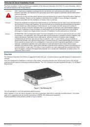
1.2 Physical Description<br />
The <strong>IDU</strong>-<strong>DV</strong> unit can be placed on a desktop or a shelf or mounted on a wall.<br />
Top panel<br />
Cover<br />
Telephone connections<br />
Connection to data equipment<br />
Power and alarm LEDS<br />
ODU Reset button<br />
RJ-45 WAN connector to ODU<br />
Power jack<br />
Figure 1-1: <strong>IDU</strong>-<strong>DV</strong> Unit<br />
Figure 1-1 shows the <strong>IDU</strong>-<strong>DV</strong> unit and Table 1-1 lists the connectors.<br />
Table 1-1: Connectors<br />
Name Connector Functionality<br />
TEL1 RJ-11 Connection to telephone line 1<br />
TEL2 RJ-11 Connection to telephone line 2<br />
User Ethernet (LAN) 10/100Base-T (RJ-45) Connection to the user's data equipment<br />
Radio (WAN) 10/100Base-T (RJ-45) Connection to the ODU<br />
Power input<br />
Connection to AC/DC 15V/2A wall mount adapter<br />
<strong>BreezeMAX</strong> <strong>IDU</strong>-<strong>DV</strong> <strong>Product</strong> <strong>Manual</strong> 3
Chapter 1 - <strong>Product</strong> Description<br />
1.2.1 LEDs<br />
1.2.1.1 LEDS on Top Panel<br />
The <strong>IDU</strong>-<strong>DV</strong> has LEDs on the top panel that indicate the status of the connection.<br />
Figure 1-2 shows this panel and Table 1-2 lists the indicators.<br />
Figure 1-2: LED Indicators on Top Panel<br />
Table 1-2: LED Indicators on Top Panel<br />
Name<br />
TEL 2<br />
TEL 1<br />
LAN<br />
WAN<br />
Functionality<br />
Green: Telephone line 2 has been registered in a SIP server<br />
Green: Telephone line 1 has been registered in a SIP server<br />
Green: A PC has been connected to the LAN port of the <strong>IDU</strong>-<strong>DV</strong><br />
Green: The PRO CPE attached to the <strong>IDU</strong>-<strong>DV</strong> is registered in the Base Station<br />
4 <strong>BreezeMAX</strong> <strong>IDU</strong>-<strong>DV</strong> <strong>Product</strong> <strong>Manual</strong>
Physical Description<br />
1.2.1.2 LEDS on Unit Base<br />
There are LEDs on the base on the base of the unit that indicate the power status.<br />
Figure 1-3 shows this panel and Table 1-3 lists the power and alarm status<br />
indicators.<br />
Figure 1-3: Power LEDs on Unit Base<br />
Table 1-3: Power LEDs<br />
Name<br />
Power<br />
Alarm<br />
Functionality<br />
Green:The <strong>IDU</strong>-<strong>DV</strong> is connected to the power supply.<br />
Note: This LED blinks when the unit is disconnected from the power supply and is powered<br />
by the backup batteries<br />
Red: - Backup batteries are discharged<br />
- Incorrect power supply is connected<br />
- PRO CPE is not properly connected to the <strong>IDU</strong>-<strong>DV</strong><br />
<strong>BreezeMAX</strong> <strong>IDU</strong>-<strong>DV</strong> <strong>Product</strong> <strong>Manual</strong> 5
Chapter 1 - <strong>Product</strong> Description<br />
1.2.2 Reset Buttons<br />
The <strong>IDU</strong>-<strong>DV</strong> has 2 RESET buttons, one on the unit as shown in Figure 1-1 and<br />
one located on the underside of the unit as shown in Figure 1-4.<br />
Alarm<br />
Power<br />
Reset<br />
Button<br />
Figure 1-4: Underside of <strong>IDU</strong>-<strong>DV</strong> Unit<br />
1.2.2.1 Resetting the PRO CPE (Outdoor Unit)<br />
To reset the PRO CPE:<br />
1 Use a thin object to press the reset button on the <strong>IDU</strong>-<strong>DV</strong> unit (Figure 1-1).<br />
2 Wait at least 5 seconds and then release the reset button.<br />
This powers down the PRO CPE and then performs the power-up initialization.<br />
6 <strong>BreezeMAX</strong> <strong>IDU</strong>-<strong>DV</strong> <strong>Product</strong> <strong>Manual</strong>
Physical Description<br />
1.2.2.2 Resetting the <strong>IDU</strong>-<strong>DV</strong><br />
To reset the <strong>IDU</strong>-<strong>DV</strong>:<br />
• Press and hold down for 5-10 seconds to reset the <strong>IDU</strong>-<strong>DV</strong> with the factory<br />
defaults in WAN DHCP mode.<br />
• Press and hold down for more than 10 seconds to reset the <strong>IDU</strong>-<strong>DV</strong> with the<br />
factory defaults with WAN IP fixed (192.168.254.254).<br />
CAUTION<br />
Before rebooting the unit via the hardware, disconnect the power cable and remove the internal<br />
battery.<br />
1.2.3 Connections to the PRO CPE (Outdoor Unit)<br />
The <strong>IDU</strong>-<strong>DV</strong> is powered from the mains using an AC power adapter and connects<br />
to the PRO CPE via a Category 5E Ethernet cable carrying the Ethernet data<br />
between the two units, as well as power (-55 VDC) and control signals to the PRO<br />
CPE and status indication from the PRO CPE.<br />
The total length of the Indoor-to-Outdoor cable, together with the length of the<br />
Ethernet cable connecting the <strong>IDU</strong>-<strong>DV</strong> to the data equipment, should not exceed<br />
100 meters.<br />
For instructions on installing the PRO CPE, refer to the <strong>BreezeMAX</strong> CPEs <strong>Product</strong><br />
<strong>Manual</strong>.<br />
CAUTION<br />
Do not connect data equipment (such as PC) to the Radio (WAN) port using the <strong>IDU</strong>-ODU cable<br />
(8-wire). This cable transfers high DC power to the ODU, and this may harm other equipment<br />
connected to it. Use a standard Ethernet cable (4-wire) instead.<br />
Table 1-4: RJ45 Connector Pins<br />
Pin Signal Name Description I/O Type<br />
1 RXD_P Ethernet Rx Data + (positive),from 10/100Base-T port Output from <strong>IDU</strong>-<strong>DV</strong><br />
2 RXD_N Ethernet Rx Data - (negative),from 10/100Base-T port Output from <strong>IDU</strong>-<strong>DV</strong><br />
3 TXD_P Ethernet Tx Data + (positive), to 10/100BASE-T port Input to <strong>IDU</strong>-<strong>DV</strong><br />
6 TXD_N Ethernet Tx Data - (negative),to 10/100BASE-T port Input to <strong>IDU</strong>-<strong>DV</strong><br />
<strong>BreezeMAX</strong> <strong>IDU</strong>-<strong>DV</strong> <strong>Product</strong> <strong>Manual</strong> 7
Chapter 1 - <strong>Product</strong> Description<br />
1.3 Specifications<br />
1.3.1 Telephony and Fax Services<br />
Item<br />
Description<br />
No. of POTS lines 1 or 2<br />
VoIP Standard SIP (RFC 3261)<br />
Maximum cable length<br />
REN per line<br />
Internal Class 5 Services<br />
External Class 5 Services<br />
Fax<br />
Calling Number Identification (CNI)<br />
3rd party initiated pause and rerouting<br />
500 m<br />
3 REN<br />
Call Waiting, 3-party call, call hold and call alteration, differentiated<br />
ringing tones (refer to Appendix A for more details)<br />
Activation/deactivation of class 5 services supported by the IP-telephony<br />
system<br />
G3 compliant V.17 14.4 Kbps fax reception and transmission using the<br />
T.38 standard (or in-band using G.711 codec)<br />
FSK, DTMF<br />
External rerouting of media stream during speech, e.g. for pre-paid<br />
calling card and record announcement<br />
DTMF In-band and out-band using H.245 and H.225<br />
Regional Settings Telephony signals, tones and cadences (see Appendix B)<br />
Payphone<br />
Reverse Polarity. Pulse metering 12/16KHz when connected to the<br />
PTSN through an <strong>Alvarion</strong> gateway<br />
1.3.2 Security<br />
Item<br />
VLAN<br />
Authentication<br />
Description<br />
Support IEEE 802.1Q with up to 16 VLAN IDs<br />
Per call authentication and registration<br />
8 <strong>BreezeMAX</strong> <strong>IDU</strong>-<strong>DV</strong> <strong>Product</strong> <strong>Manual</strong>
Specifications<br />
1.3.3 Voice Quality<br />
Item<br />
Voice Codecs<br />
Description<br />
• G.711 Ulaw<br />
• G.711 Alaw<br />
• G.729ab<br />
Prioritization<br />
• IEEE 802.1p layer-2 prioritization<br />
• DiffServ layer-3 prioritization<br />
General<br />
• Adaptive jitter buffer<br />
• Echo cancellation<br />
• Speech sampling rate: 10-60 ms<br />
• Silence suppression with comfort noise<br />
1.3.4 Configuration and Management<br />
Item<br />
Management Options<br />
Description<br />
• Internal Web Server<br />
• SNMP<br />
SNMP Agents<br />
SNMPv1 client MIB II (RFC 1213), Private MIB<br />
Plug & Play Functionality DHCP, including support messages option 60, 61, 43<br />
Software Upgrade<br />
Configuration Download<br />
Using TFTP<br />
Using TFTP<br />
1.3.5 Bridge Functionality<br />
Item<br />
Supported Ethernet Devices<br />
Unknown address Forwarding Policy<br />
Bridge Aging Time<br />
Description<br />
Up to 32 MAC addresses<br />
Forward Unknown<br />
180 seconds<br />
<strong>BreezeMAX</strong> <strong>IDU</strong>-<strong>DV</strong> <strong>Product</strong> <strong>Manual</strong> 9
Chapter 1 - <strong>Product</strong> Description<br />
1.3.6 Physical Specifications<br />
Item<br />
Details<br />
Dimensions (H x L x W) 115 x 200 x 150<br />
Weight (not including battery)<br />
Operating temperature<br />
0.6 kg<br />
-5 to +45° C<br />
1.3.7 Regulatory Standards Compliance<br />
Type<br />
Standard<br />
EMC EN 301489-1/4<br />
Safety EN 60950-1, UL 60950-1<br />
Environmental<br />
ETS300019-2-3<br />
MTBF 150,000<br />
1.3.8 Powering<br />
Type<br />
Battery backup<br />
Mains<br />
Description<br />
Internal rechargeable 12V 3.2AH SLA battery supplies power for at least<br />
2 hours.<br />
Wall mount AC/DC 15V/2A adapter.<br />
10 <strong>BreezeMAX</strong> <strong>IDU</strong>-<strong>DV</strong> <strong>Product</strong> <strong>Manual</strong>
2<br />
Chapter 2 - Installation<br />
In This Chapter:<br />
• “Installation Requirements” on page 12<br />
• “Installation and Commissioning” on page 13<br />
• “Managing the CPE ODU” on page 21<br />
• “Wall Mounting the <strong>IDU</strong>-<strong>DV</strong> (Optional)” on page 22
Chapter 2 - Installation<br />
2.1 Installation Requirements<br />
The following accessories must be ordered separately from <strong>Alvarion</strong>.<br />
2.1.1 Additional Requirements<br />
• PRO CPE (outdoor unit).<br />
• Rechargeable 12V 3.2AH SLA backup battery<br />
• Power cable for connection to AC mains.<br />
• Mains plug adapter or termination plug (if the power plug on the supplied AC<br />
power cord does not fit local power outlets).<br />
• An <strong>IDU</strong> ODU Category 5E Ethernet cable (8 wire) for connecting the <strong>IDU</strong>-<strong>DV</strong><br />
(indoor unit) to the PRO CPE (outdoor unit).<br />
• An Ethernet cable (4 wire) for connecting to the user's data equipment<br />
(straight for connecting to a PC, crossed for connecting to a hub/switch).<br />
NOTE<br />
The total length of the cable connecting the <strong>IDU</strong>-<strong>DV</strong> to the PRO CPE and the cable connecting the<br />
<strong>IDU</strong>-<strong>DV</strong> to a PC, should not exceed 100m.<br />
• Standard phone cable(s) with RJ11 connector.<br />
• PC with an Ethernet card.<br />
• Wall mounting kit (optional)<br />
12 <strong>BreezeMAX</strong> <strong>IDU</strong>-<strong>DV</strong> <strong>Product</strong> <strong>Manual</strong>
Installation and Commissioning<br />
2.2 Installation and Commissioning<br />
The <strong>IDU</strong>-<strong>DV</strong> must be installed indoors and can be placed on a desktop or shelf, or<br />
can be mounted on a wall. Its location should take the necessary connections to<br />
mains power, PRO CPE and user's data/telephony equipment into account.<br />
It is assumed that installation and commissioning of the PRO CPE has already<br />
been completed. For instructions on installing the PRO CPE, refer to the CPEs<br />
<strong>Product</strong> <strong>Manual</strong>.<br />
2.2.1 Connecting the <strong>IDU</strong>-<strong>DV</strong> to Subscriber’s<br />
Equipment<br />
This section describes how to connect the <strong>IDU</strong>-<strong>DV</strong> to the subscriber's equipment<br />
(telephone sets, fax machines, PCs).<br />
1 Make sure that the <strong>IDU</strong>-<strong>DV</strong> is not connected to any power source.<br />
2 Make sure that the internal battery is not installed. Plug subscriber telephone<br />
cables into the RJ-11 jacks.<br />
2.2.2 Inserting the Internal Backup Battery<br />
The <strong>IDU</strong>-<strong>DV</strong> is supplied as a closed unit with the internal battery supplied<br />
separately and must be installed in the <strong>IDU</strong>-<strong>DV</strong> after connecting the <strong>IDU</strong>-<strong>DV</strong> to<br />
the subscriber’s equipment as described in Section 2.2.1. Replacement batteries<br />
can be ordered from <strong>Alvarion</strong> or purchased elsewhere (see Section 2.2.2.1 for<br />
battery specifications and characteristics).<br />
The backup battery is shipped discharged. The battery charges when the <strong>IDU</strong>-<strong>DV</strong><br />
is connected to a 110-230V AC power supply and takes 24 hours to charge fully.<br />
When fully charged, the internal backup battery provides at least 2 hours of<br />
operation without external power.<br />
Figure 2-1 shows the different components of the <strong>IDU</strong>-<strong>DV</strong>.<br />
CAUTION<br />
The internal battery should be inserted by an experienced installer only.<br />
<strong>BreezeMAX</strong> <strong>IDU</strong>-<strong>DV</strong> <strong>Product</strong> <strong>Manual</strong> 13
Chapter 2 - Installation<br />
Cover<br />
Battery<br />
<strong>IDU</strong>-<strong>DV</strong><br />
Figure 2-1: Open <strong>IDU</strong>-<strong>DV</strong><br />
To insert the internal backup battery:<br />
1 Place the <strong>IDU</strong>-<strong>DV</strong> on a level surface and using a flathead screw driver, gently<br />
push on the corners of the cover to release each of the four latches and remove<br />
the cover.<br />
14 <strong>BreezeMAX</strong> <strong>IDU</strong>-<strong>DV</strong> <strong>Product</strong> <strong>Manual</strong>
Installation and Commissioning<br />
Figure 2-2: <strong>IDU</strong>-<strong>DV</strong> with cover removed<br />
2 Place the battery in the unit, remove the plastic pieces covering the battery (+)<br />
and (-) terminals, connect the black wire to the negative (black) terminal on the<br />
battery and connect the red wire to the positive (red) terminal on the battery<br />
(Figure 2-3).<br />
<strong>BreezeMAX</strong> <strong>IDU</strong>-<strong>DV</strong> <strong>Product</strong> <strong>Manual</strong> 15
Chapter 2 - Installation<br />
Figure 2-3: Connecting Internal Battery 1<br />
CAUTION<br />
Connecting the wires to the incorrect battery terminals, according to polarity, can cause damage<br />
to the equipment.<br />
3 Replace the cover and click the two latches on each side in place.<br />
NOTE<br />
Only use batteries with a nominal voltage of 12 VDC with specifications as noted in<br />
Section 2.2.2.1.<br />
16 <strong>BreezeMAX</strong> <strong>IDU</strong>-<strong>DV</strong> <strong>Product</strong> <strong>Manual</strong>
Installation and Commissioning<br />
2.2.2.1 Battery data<br />
The internal backup battery is a sealed, maintenance-free lead-acid battery.<br />
Table 2-1: Specifications and Characteristics of Internal Backup Battery<br />
Nominal voltage<br />
Rated capacity<br />
Terminal<br />
12V<br />
3.2 AH<br />
Standard F1<br />
187E fastern tab<br />
Length<br />
134 mm<br />
Width 67 mm<br />
Height 60 mm<br />
Weight<br />
approx 1.3 kg<br />
2.2.3 Commissioning the <strong>IDU</strong>-<strong>DV</strong><br />
1 Connect the power adapter supplied with the unit to the <strong>IDU</strong>-<strong>DV</strong> and plug into<br />
the power supply. The power indicator turns green, indicating that the power<br />
has been connected and a second indicator briefly flashes red and then turns<br />
off.<br />
The LEDs in the top panel (LAN, WAN, TEL1 and TEL2) flash green once. The<br />
LAN and WAN LEDs then flash again twice and then all the LEDs turn off.<br />
NOTE<br />
The PRO CPE receives power directly from the <strong>IDU</strong>-<strong>DV</strong> and not from a separate power source.<br />
2 Connect a PC to the User Ethernet (LAN) port on the <strong>IDU</strong>-<strong>DV</strong> using the<br />
Ethernet cable supplied with the PRO CPE. The LAN indicator on the top panel<br />
of the <strong>IDU</strong>-<strong>DV</strong> turns green.<br />
CAUTION<br />
Do not connect data equipment (such as PC) to the Radio (WAN) port using the <strong>IDU</strong>-ODU cable<br />
(8-wire). This cable transfers high DC power to the ODU, and this may harm other equipment<br />
connected to it. Use a standard Ethernet cable (4-wire) instead.<br />
3 Configure the PC with a static IP address 192.168.254.2 and subnet mask<br />
255.255.255.0.<br />
<strong>BreezeMAX</strong> <strong>IDU</strong>-<strong>DV</strong> <strong>Product</strong> <strong>Manual</strong> 17
Chapter 2 - Installation<br />
NOTE<br />
The <strong>IDU</strong>-<strong>DV</strong> can be accessed via the LAN port or through <strong>BreezeMAX</strong> connectivity.<br />
4 Open a web browser and connect to the unit by entering<br />
http://192.168.254.254. in the address field.<br />
5 If the Web Configuration Server is password protected, you will be prompted to<br />
enter your username and password in order to log in to the system. The<br />
default username is operator and the default password is installer. See<br />
Chapter 3 for details on using the Web Configuration Server.<br />
6 Configure the necessary parameters according to instructions supplied by the<br />
system administrator. The mandatory parameters that must be configured<br />
properly are:<br />
Enable DRAP (in BW Reservation page) only if DRAP is supported by the<br />
wireless system (currently DRAP is supported by <strong>BreezeMAX</strong> FDD<br />
equipment with SW version 1.5 or higher and <strong>BreezeMAX</strong> TDD with SW<br />
version 4.0). Uncheck if DRAP is not used.<br />
LAN/WAN VLAN Tagged Port Membership parameters (VLAN page) and<br />
VoIP VLAN parameters (VoIP VLAN Configuration page).<br />
Telephony parameters (per line) in the SIP Configuration Telephone page:<br />
Telephone Line Enable/Disable, primary SIP Server Gate Keeper<br />
parameters, User Name and Password (SIP model), Telephone Number,<br />
Telephone domain name (SIP model).<br />
WAN IP parameters (WAN Configuration page): For operation as a DHCP<br />
client, check the Obtain WAN Configuration dynamically. For static IP<br />
configuration, check the Specify fixed WAN configuration option and<br />
specify the IP Address, Subnet Mask and Default Gateway.<br />
7 Restart the unit from the Restart page.<br />
8 If VLANs are configured for management, you will lose management from the<br />
PC, unless the packets are tagged from the PC towards the <strong>IDU</strong>-<strong>DV</strong>. To resume<br />
management capabilities, return to factory defaults.<br />
9 Disconnect the PC used for configuration.<br />
10 Use standard telephone cord(s) with RJ-11 termination to connect the<br />
telephony equipment to the unit.<br />
11 Verify proper operation using the LED indicators (see Table 1-2 and<br />
Table 1-3).<br />
18 <strong>BreezeMAX</strong> <strong>IDU</strong>-<strong>DV</strong> <strong>Product</strong> <strong>Manual</strong>
Installation and Commissioning<br />
12 To verify data connectivity, from the end-user's PC or from a portable PC<br />
connected to the unit, try to connect to the Internet or to ping another unit in<br />
the network.<br />
13 Verify proper telephony operation by establishing a call to another telephone<br />
(for each enabled line).<br />
NOTE<br />
The PRO CPE can operate independently of the <strong>IDU</strong>-<strong>DV</strong> to provide data services. See the<br />
<strong>Alvarion</strong> CPEs <strong>Product</strong> <strong>Manual</strong> for details.<br />
2.2.4 Grounding<br />
The radio unit and antenna (ODU) are installed on a pole at a subscriber location.<br />
The shielded Category 5E Ethernet outdoor cable for connecting the <strong>IDU</strong>-<strong>DV</strong><br />
(indoor unit) to the PRO CPE (outdoor unit) consists of twisted pair wires for<br />
Ethernet data and another pair of wires for the DC supply. This cable connects to<br />
the indoor unit via a grounded external lightning protector box (recommended for<br />
high Keraunic areas). The external lightning box is connected to an earth<br />
termination via a down-conductor.<br />
The ground cable of the radio unit and an optional lightning protector ground lead<br />
are attached to a metal grounding plate using cable terminals. The metal<br />
grounding plate runs to an earth termination. See Figure 2-4 for details.<br />
<strong>BreezeMAX</strong> <strong>IDU</strong>-<strong>DV</strong> <strong>Product</strong> <strong>Manual</strong> 19
Chapter 2 - Installation<br />
Figure 2-4: Grounding<br />
20 <strong>BreezeMAX</strong> <strong>IDU</strong>-<strong>DV</strong> <strong>Product</strong> <strong>Manual</strong>
Managing the CPE ODU<br />
2.3 Managing the CPE ODU<br />
• Access the CPE ODU monitor program from a PC connected to the LAN port of<br />
the <strong>IDU</strong>-<strong>DV</strong>. The Monitor program uses the fixed IP address 192.168.254.251<br />
with the subnet mask 255.255.255.0. The PC used for accessing the Monitor<br />
program should be configured to belong to the same subnet. It is<br />
recommended to set the PC's IP address to 192.168.254.250, which is the<br />
default TFTP Server IP address in the Monitor (required for downloading SW<br />
versions for the CPE ODU and for downloading/uploading configuration files).<br />
CAUTION<br />
Do not connect data equipment (such as PC) to the Radio (WAN) port using the <strong>IDU</strong>-ODU cable<br />
(8-wire). This cable transfers high DC power to the ODU, and this may harm other equipment<br />
connected to it. Use a standard Ethernet cable (4-wire) instead.<br />
• Information about DRAP-enabled Gateways can be viewed in the Base<br />
Station's Monitor program (in the Voice/Networking Gateways option of the<br />
Configuration menu). The displayed information includes Gateway's type, IP<br />
Address, and the VLAN ID used for management.<br />
• In general, the same VLAN should be configured in the <strong>IDU</strong>-<strong>DV</strong> for<br />
Management (Default VLAN ID) and Voice (RTP and Signaling) as the <strong>IDU</strong>-<strong>DV</strong><br />
uses one IP address for two VLANs and the default router in the backbone<br />
cannot operate in this mode.<br />
• To support the required quality of service when DRAP is used, provision the<br />
correct VoIP Service. If DRAP is not used, provision an L2 Service with a CG<br />
connection (refer to the Base Station/Micro Base Station System <strong>Manual</strong> for<br />
details).<br />
<strong>BreezeMAX</strong> <strong>IDU</strong>-<strong>DV</strong> <strong>Product</strong> <strong>Manual</strong> 21
Chapter 2 - Installation<br />
2.4 Wall Mounting the <strong>IDU</strong>-<strong>DV</strong> (Optional)<br />
The wall mounting kit for the <strong>IDU</strong>-<strong>DV</strong> includes a bracket, 2 screws, and 2 plastic<br />
anchors. Refer to Figure 2-5.<br />
1 If anchors are needed (wall-board, plaster board, etc.), drill two holes for the<br />
anchors using a 6 mm drill bit and insert anchors. The distance between the<br />
two holes should be 86 mm. Use the drilling template supplied with the wall<br />
mounting kit.<br />
2 Fasten the two screws provided with the kit directly to the anchors.<br />
3 Use the two hangers on the rear to hang the mounting bracket on the two<br />
screws. Make sure the bracket is stable.<br />
4 Insert one side of the <strong>IDU</strong>-<strong>DV</strong>'s base diagonally under the designated rail.<br />
5 Gently apply pressure on the opposite side of the <strong>IDU</strong>-<strong>DV</strong>, until a clicking<br />
sound is heard and the two bracket studs are locked onto the <strong>IDU</strong>-<strong>DV</strong>'s base.<br />
To dismount the <strong>IDU</strong>-<strong>DV</strong>, gently push the two bracket studs in the direction of the<br />
wall and lift the <strong>IDU</strong>-<strong>DV</strong> diagonally. Pull the <strong>IDU</strong>-<strong>DV</strong> until free from the rail.<br />
Figure 2-5: <strong>IDU</strong>-<strong>DV</strong> Wall Mount<br />
22 <strong>BreezeMAX</strong> <strong>IDU</strong>-<strong>DV</strong> <strong>Product</strong> <strong>Manual</strong>
3<br />
Chapter 3 - Using the Web Configuration<br />
Server<br />
In This Chapter:<br />
• “Introduction to the Web Configuration Server” on page 24<br />
• “Accessing the Web Configuration Server” on page 25<br />
• “Using the Web Configuration Server” on page 26<br />
• “Home Menu - <strong>Product</strong> Info Page” on page 28<br />
• “WAN Menu” on page 30<br />
• “VLAN Tagging Menu” on page 34<br />
• “Telephone Menu” on page 42<br />
• “BW Reservation - DRAP Configuration Page” on page 62<br />
• “System Menu” on page 65<br />
• “Upgrade Page” on page 72<br />
• “Restart Page” on page 74<br />
• “Logout Page” on page 75<br />
• “Parameters Summary” on page 76
Chapter 3 - Using the Web Configuration Server<br />
3.1 Introduction to the Web Configuration<br />
Server<br />
The <strong>IDU</strong>-<strong>DV</strong> can be configured using the following methods:<br />
• The Web Configuration Server<br />
• An .ini-file loaded into the unit from a TFTP-server or automatically<br />
downloaded using DHCP option 43.<br />
This document describes the configuration using the Web Configuration Server.<br />
24 <strong>BreezeMAX</strong> <strong>IDU</strong>-<strong>DV</strong> <strong>Product</strong> <strong>Manual</strong>
Accessing the Web Configuration Server<br />
3.2 Accessing the Web Configuration Server<br />
To manage the unit you must have prior knowledge of its WAN IP Address. Follow<br />
the steps below to access the Web Configuration Server:<br />
1 Open a web browser.<br />
2 Enter the WAN IP address of the unit in the Address field of the browser and<br />
click Enter. e.g., http://192.168.254.254 (default).<br />
3 If the Web Configuration Server is password protected, you will be prompted<br />
to enter your user name and password in order to login to the system.<br />
To login with operator privileges (full access and read/write privileges), the<br />
default user name is operator and the default password is installer.<br />
To login with administrator privileges (partial access and read/write<br />
privileges), the default user name is admin. No password is required.<br />
4 The Web Configuration Server main view appears on the screen.<br />
<strong>BreezeMAX</strong> <strong>IDU</strong>-<strong>DV</strong> <strong>Product</strong> <strong>Manual</strong> 25
Chapter 3 - Using the Web Configuration Server<br />
3.3 Using the Web Configuration Server<br />
The Web Configuration Server view consists of a number of menu links (to the<br />
left). Clicking on each of them will display the configuration/status page for the<br />
selected menu item, with the applicable content (configurable parameters/options<br />
or status information) in the main area. Several pages include a page selection bar<br />
at the top of the page, enabling selection between several pages related to the<br />
same menu item. The displayed pages may vary depending on user privileges.<br />
Figure 3-1: Web Configuration Page<br />
CAUTION<br />
Many pages include a "Save Settings" button. Click on the Save Settings button before selecting<br />
another page/menu item, or before quitting the application. The Save Settings functionality in many<br />
cases is per page - if you leave the page without clicking the Save Settings button, all the changes in<br />
the page will be lost.<br />
Changes to most of the settings are applied only after restarting the unit (refer to<br />
Section 3.11).<br />
26 <strong>BreezeMAX</strong> <strong>IDU</strong>-<strong>DV</strong> <strong>Product</strong> <strong>Manual</strong>
Using the Web Configuration Server<br />
CAUTION<br />
There is no control that the entered values are valid or have the correct format or range. If invalid<br />
values are entered, access to the unit may be lost and in that case a factory default procedure must be<br />
performed. Refer to Section 1.2.2.2 for information about how to reset the <strong>IDU</strong>-<strong>DV</strong> to factory default<br />
parameters.<br />
<strong>BreezeMAX</strong> <strong>IDU</strong>-<strong>DV</strong> <strong>Product</strong> <strong>Manual</strong> 27
Chapter 3 - Using the Web Configuration Server<br />
3.4 Home Menu - <strong>Product</strong> Info Page<br />
The <strong>Product</strong> info page provides general information on the <strong>IDU</strong>-<strong>DV</strong>.<br />
Figure 3-2: <strong>Product</strong> Info Page<br />
The <strong>Product</strong> info page includes the following components:<br />
Table 3-1: <strong>Product</strong> Info Page Parameters<br />
Parameter<br />
Name<br />
Mac address<br />
Serial Number<br />
<strong>Product</strong> number<br />
<strong>Product</strong> revision<br />
<strong>Product</strong>ion week<br />
Default configuration<br />
Downloader revision<br />
Reported download status<br />
Main software revision<br />
Operator defaults revision<br />
Description<br />
The unit's model<br />
The MAC address of the unit<br />
The serial number of the unit<br />
Not Used<br />
The hardware revision<br />
<strong>Product</strong>ion date in the format w. is the year (two last digits)<br />
and ww is the week (two digits).<br />
The unit's configuration<br />
The revision of the SW download SW module.<br />
The status of the SW download operation. For more details refer to<br />
Section 3.10.1.<br />
The unit's main SW version<br />
The custom .ini file (if exists)<br />
28 <strong>BreezeMAX</strong> <strong>IDU</strong>-<strong>DV</strong> <strong>Product</strong> <strong>Manual</strong>
Home Menu - <strong>Product</strong> Info Page<br />
In any case of contact with Customer Service, include the Default configuration,<br />
Downloader revision, Main software revision and Operator defaults revision (.ini<br />
file) if exists.<br />
<strong>BreezeMAX</strong> <strong>IDU</strong>-<strong>DV</strong> <strong>Product</strong> <strong>Manual</strong> 29
Chapter 3 - Using the Web Configuration Server<br />
3.5 WAN Menu<br />
The WAN menu page includes settings related to the operation and functionality<br />
on the WAN (network) side of the unit.<br />
NOTE<br />
Be careful when setting these parameters to avoid conflicts in the network.<br />
The WAN page selection bar includes the following options:<br />
• WAN Status (Section 3.5.1)<br />
• WAN Configuration (Section 3.5.2)<br />
3.5.1 WAN Status Page<br />
Figure 3-3: WAN Status Page<br />
The WAN Status page includes the following components:<br />
30 <strong>BreezeMAX</strong> <strong>IDU</strong>-<strong>DV</strong> <strong>Product</strong> <strong>Manual</strong>
WAN Menu<br />
Table 3-2: WAN Status Page Parameters<br />
Parameter<br />
Description<br />
Interface Status<br />
Enabled<br />
Service<br />
Bridge Status<br />
Protocol<br />
Interface Status<br />
The administrative status of the WAN port: Yes or No. In the current version<br />
the administrative status cannot be disabled.<br />
The configured operation mode. In current version it is always Bridged.<br />
The method of handling packets with an unknown destination address. In the<br />
current version it is always Forwarding.<br />
The protocol used for data transmission: In the current version it is always<br />
Ethernet.<br />
The operational status of the WAN port: Up or Down.<br />
Network Settings<br />
Identity<br />
Dynamic IP Assignment<br />
The unit’s ID. The default ID is the unit’s MAC address.<br />
The method of configuring IP Address, Subnet Mask, Default Gateway and<br />
DNS Address, as defined in the WAN Configuration page:<br />
• Yes (via DHCP): the parameters are obtained from a DHCP server.<br />
• No: the parameters are configured manually<br />
IP Address<br />
MAC Address<br />
Subnet Mask<br />
Default Gateway<br />
DNS Address<br />
Host Name<br />
Domain Name<br />
VLAN Tag<br />
Priority Tag<br />
The IP address of the unit<br />
The MAC address of the unit<br />
The IP Subnet Mask<br />
The Default Gateway address<br />
IP DNS Server address<br />
The host name as defined in the WAN Configuration page<br />
The Domain Name as defined in the WAN Configuration page<br />
The VLAN ID tag defined for management traffic<br />
The Priority tag defined for management traffic<br />
Click on the Update button to refresh the display.<br />
<strong>BreezeMAX</strong> <strong>IDU</strong>-<strong>DV</strong> <strong>Product</strong> <strong>Manual</strong> 31
Chapter 3 - Using the Web Configuration Server<br />
3.5.2 WAN Configuration Page<br />
Figure 3-4: WAN Configuration Page<br />
The WAN Configuration page includes the following components:<br />
Table 3-3: WAN Configuration Page Parameters<br />
Parameter<br />
Device Operating Mode<br />
Obtain WAN configuration using DHCP<br />
Description<br />
The operating mode of the unit. In current version the operation mode<br />
is always Bridge.<br />
Select this option to obtain IP parameters from a DHCP server.<br />
32 <strong>BreezeMAX</strong> <strong>IDU</strong>-<strong>DV</strong> <strong>Product</strong> <strong>Manual</strong>
WAN Menu<br />
Table 3-3: WAN Configuration Page Parameters<br />
Parameter<br />
Client identity<br />
Description<br />
Applicable only if the "Obtain WAN configuration dynamically" option<br />
is selected. The method used for identifying the client (Option 61).<br />
The options are:<br />
Standard: The unit's MAC address<br />
Custom: An identification string of up to 25 characters. The default is<br />
null (an empty string)<br />
Vendor ID<br />
Applicable only if the "Obtain WAN configuration dynamically" option<br />
is selected. The Vendor ID (Option 60). A string of up to 25<br />
characters. The default used by the unit is “VoIP” (not displayed).<br />
Specify static WAN configuration Select this option to configure the IP parameters manually. .<br />
IP Address<br />
Subnet Mask<br />
Default Gateway<br />
DNS Address<br />
Host Name<br />
Applicable only if the "Specify fixed WAN configuration" option is<br />
selected. The IP address of the unit. The default is 192.168.254.254<br />
Applicable only if the "Specify fixed WAN configuration" option is<br />
selected. The IP Subnet Mask. The default is 255.255.255.0<br />
Applicable only if the "Specify fixed WAN configuration" option is<br />
selected. The Default Gateway address. The default is none (empty)<br />
Applicable only if the "Specify fixed WAN configuration" option is<br />
selected. IP DNS Server address. The default is none (empty)<br />
The Host name for clients. A string of up to 25 characters. The default<br />
is null (an empty string).<br />
Domain Name The Domain Name for client resolution. A string of up to 25<br />
characters. The default is null (an empty string).<br />
Click on the Save WAN Settings button before leaving the page to save the new<br />
settings. The new settings will be applied after restarting the unit.<br />
<strong>BreezeMAX</strong> <strong>IDU</strong>-<strong>DV</strong> <strong>Product</strong> <strong>Manual</strong> 33
Chapter 3 - Using the Web Configuration Server<br />
3.6 VLAN Tagging Menu<br />
The VLAN Tagging page selection bar includes the following options:<br />
• VLAN Tagging (Section 3.6.1)<br />
• VoIP VLAN Configuration (Section 3.6.3)<br />
3.6.1 VLAN Tagging Page<br />
The <strong>IDU</strong>-<strong>DV</strong> supports 802.1Q VLAN standard, allowing IEEE 802 Local Area<br />
Networks (LANs) of all types to be connected together with Media Access Control<br />
(MAC) Bridges, as specified in ISO/IEC 15802-3. This standard defines the<br />
operation of Virtual LAN (VLAN) Bridges that permit the definition, operation and<br />
administration of Virtual LAN topologies within a bridged LAN infrastructure.<br />
Figure 3-5: VLAN Tagging Page<br />
34 <strong>BreezeMAX</strong> <strong>IDU</strong>-<strong>DV</strong> <strong>Product</strong> <strong>Manual</strong>
VLAN Tagging Menu<br />
The VLAN page enables defining up to 16 VLANs, and it includes the following<br />
components:<br />
Table 3-4: VLAN Page Parameters<br />
Parameter<br />
Tagged Port Membership<br />
Untagged VLAN ID<br />
Description<br />
A table displaying the defined VLANs. For details on modifying the<br />
table refer to Section 3.6.2 below.<br />
The VLAN ID that is defined for untagged data on the WAN port (text<br />
box on the left side) and the LAN port (text box on the right side).<br />
This parameter must be consistent with a properly configured VLAN<br />
in the tagged port membership. For examples on VLAN<br />
configuration, see Section 3.6.4.<br />
The range for both parameters is from 1 to 4094.<br />
Default VLAN ID<br />
The text box on the left side is for the WAN port. This is the VLAN<br />
defined for management frames (SNMP, HTTP, TFTP) arriving on the<br />
WAN port.<br />
The DRAP packets are tagged with the default VLAN configuration.<br />
The range is from 1 to 4094.<br />
3.6.2 Adding and Deleting VLANs<br />
To add a VLAN:<br />
1 Click on the Add VLAN button. The VLAN Editor (Add) is displayed:<br />
<strong>BreezeMAX</strong> <strong>IDU</strong>-<strong>DV</strong> <strong>Product</strong> <strong>Manual</strong> 35
Chapter 3 - Using the Web Configuration Server<br />
Figure 3-6: VLAN Editor (Add VLAN)<br />
2 Enter the VLAN ID (1 to 4094), VLAN NAME (A descriptive string of printable<br />
characters. Do not use special characters such as space or comma), and the<br />
VLAN priority tag (0 to 7).<br />
3 If applicable packets need to be tagged on the WAN/LAN port, check the<br />
relevant Yes option. Otherwise check the No option. Note that only one VLAN<br />
can be untagged on each port (or on both).<br />
4 Click OK. The newly added entry will be added to the Tagged Port Membership<br />
table.<br />
To delete a VLAN from the Tagged Port Membership table:<br />
1 Click on the row ID number of the entry you wish to remove. The VLAN Editor<br />
(Delete) is displayed:<br />
36 <strong>BreezeMAX</strong> <strong>IDU</strong>-<strong>DV</strong> <strong>Product</strong> <strong>Manual</strong>
VLAN Tagging Menu<br />
Figure 3-7: VLAN Editor (Delete VLAN)<br />
2 Click on the Delete button. The entry will be removed from the Tagged Port<br />
Membership table.<br />
3.6.3 VoIP VLAN Configuration Page<br />
Figure 3-8: VoIP VLAN Configuration Page<br />
<strong>BreezeMAX</strong> <strong>IDU</strong>-<strong>DV</strong> <strong>Product</strong> <strong>Manual</strong> 37
Chapter 3 - Using the Web Configuration Server<br />
The VoIP VLAN configuration page enables defining the following parameters:<br />
Table 3-5: VoIP VLAN Configuration Page Parameters<br />
Parameter<br />
Description<br />
Call Signaling<br />
VLAN Tag<br />
Priority Tag<br />
The VLAN ID tag for VoIP call signaling packets. If not set, the Default<br />
VLAN ID set for WAN (in the VLAN Tagging page) will also apply for<br />
VoIP.<br />
The Priority tag for VoIP call signaling packets. If not set, the priority tag<br />
defined for the Management VLAN in the Tagged Port Membership (in<br />
the VLAN Tagging page), will also apply for VoIP.<br />
RTP<br />
VLAN Tag<br />
Priority Tag<br />
The VLAN ID tag for RTP and RTCP packets. If not set, the Default<br />
VLAN ID set for WAN (in the VLAN Tagging page) will also apply for<br />
VoIP.<br />
The Priority tag for RTP and RTCP packets. If not set, the priority tag<br />
defined for the Management VLAN in the Tagged Port Membership (in<br />
the VLAN Tagging page), will also apply for VoIP.<br />
When DRAP is enabled the same VLAN is needed for management, call signaling<br />
and RTP. In this case, the same VLAN and Priority Tags have to be configured for<br />
management (Default VLAN on WAN port in the VLAN Tagging page), Call<br />
Signaling and RTP. However when DRAP is disabled, the <strong>IDU</strong>-<strong>DV</strong> supports<br />
separation of VLANs and allows defining 3 different VLANs for management, call<br />
signaling and RTP traffic (this may require a proper router). Different Priority tags<br />
for management, call signaling and RTP can be configured. The Priority tag for<br />
management is defined in the Priority field of the management VLAN ID<br />
(configured in the Tagged Port Membership table).<br />
3.6.4 VLAN Configuration Example 1<br />
This example describes how to define the following configuration:<br />
• VLAN ID 100, VLAN Priority 7 for Voice (call signaling, RTP and RTCP) and 5<br />
for Management packets on the WAN port.<br />
• VLAN ID 200, VLAN Priority 0 for data on the WAN port and untagged to/from<br />
the LAN port.<br />
38 <strong>BreezeMAX</strong> <strong>IDU</strong>-<strong>DV</strong> <strong>Product</strong> <strong>Manual</strong>
VLAN Tagging Menu<br />
Figure 3-9: VLAN Configuration Example 1<br />
1 In the VLAN page, click Add VLAN to open the VLAN Editor.<br />
2 In the VLAN Editor, enter the follwing for Voice and Management VLAN:<br />
VLAN ID: 100<br />
VLAN NAME: Voice&Mng<br />
VLAN Priority: 5<br />
WAN: Yes<br />
LAN: No<br />
3 Click OK to add the VLAN to the Tagged Port Membership table.<br />
4 Enter the VLAN ID for Voice and Management (100) in the field Default VLAN<br />
ID on WAN port, and click Save.<br />
5 In the Page Selection bar, click on VoIP VLAN Configuration to open the VoIP<br />
VLAN Configuration page. Enter 100 in the VLAN Tag fields for both Call<br />
Signaling and RTP. Enter 7 in the Priority Tag field for both Call Signaling and<br />
RTP. Click Save VoIP VLAN Settings. Go back to the VLAN Tagging page.<br />
6 In the VLAN page, click Add VLAN to open the VLAN Editor to configure the<br />
data VLAN.<br />
7 In the VLAN Editor, enter the follwing for data:<br />
<strong>BreezeMAX</strong> <strong>IDU</strong>-<strong>DV</strong> <strong>Product</strong> <strong>Manual</strong> 39
Chapter 3 - Using the Web Configuration Server<br />
VLAN ID: 200 (an arbitrary selection-a VLAN ID is required for defining the<br />
untagged data. This VLAN tag is only used internally in the unit)<br />
VLAN NAME: Data<br />
VLAN Priority: 0<br />
WAN: Yes<br />
LAN: No<br />
8 Click OK to add the VLAN to the Tagged Port Membership table.<br />
9 Enter the VLAN ID for untagged data (200) in the fields Untagged VLAN ID on<br />
LAN port and click Save.<br />
10 Restart the unit to apply the changes.<br />
3.6.5 VLAN Configuration Example 2<br />
This example describes how to define the following configuration:<br />
• One <strong>IDU</strong>-<strong>DV</strong>.<br />
• VLAN ID 60, VLAN Priority 6 for Voice (call signaling, RTP and RTCP) and<br />
Management packets on the WAN port.<br />
• No VLAN for data packets on WAN and LAN ports.<br />
Figure 3-10: VLAN Configuration Example 2<br />
40 <strong>BreezeMAX</strong> <strong>IDU</strong>-<strong>DV</strong> <strong>Product</strong> <strong>Manual</strong>
VLAN Tagging Menu<br />
1 In the VLAN page, click Add VLAN to open the VLAN Editor.<br />
2 In the VLAN Editor, enter the follwing for Voice and Management VLAN:<br />
VLAN ID: 60<br />
VLAN NAME: Voice&Mng<br />
VLAN Priority: 6<br />
WAN: Yes<br />
LAN: No<br />
3 Click OK to add the VLAN to the Tagged Port Membership table.<br />
4 Enter the VLAN ID for Voice and Management (60) in the field Default VLAN<br />
ID on WAN port, and click Save.<br />
5 In the Page Selection bar, click on VoIP VLAN Configuration to open the VoIP<br />
VLAN Configuration page. Enter 60 in the VLAN Tag fields for both Call<br />
Signaling and RTP. Enter 6 in the Priority Tag field for both Call Signaling and<br />
RTP. Click Save VoIP VLAN Settings. Go back to the VLAN Tagging page.<br />
6 In the VLAN page, click Add VLAN to open the VLAN Editor.<br />
7 In the VLAN Editor, enter the follwing for untagged data:<br />
VLAN ID: 90 (an arbitrary selection-a VLAN ID is required for defining the<br />
untagged data. This VLAN tag is only used internally in the unit)<br />
VLAN NAME: Untagged<br />
VLAN Priority: 0<br />
WAN: No<br />
LAN: No<br />
8 Click OK to add the VLAN to the Tagged Port Membership table.<br />
9 Enter the VLAN ID for untagged data (90) in the fields Untagged VLAN ID on<br />
LAN port and Untagged VLAN ID on WAN port, and click Save.<br />
10 Restart the unit to apply the changes.<br />
<strong>BreezeMAX</strong> <strong>IDU</strong>-<strong>DV</strong> <strong>Product</strong> <strong>Manual</strong> 41
Chapter 3 - Using the Web Configuration Server<br />
3.7 Telephone Menu<br />
The Telephone page selection bar includes the following options:<br />
• SIP (Section 3.7.1)<br />
• SIP Extensions (Section 3.7.2)<br />
• NAT (Section 3.7.3)<br />
• STUN Client (Section 3.7.4)<br />
• ToS (Section 3.7.5)<br />
• Line Configuration (Section 3.7.6)<br />
• Line test (Section 3.7.7)<br />
42 <strong>BreezeMAX</strong> <strong>IDU</strong>-<strong>DV</strong> <strong>Product</strong> <strong>Manual</strong>
Telephone Menu<br />
3.7.1 SIP Configuration Page<br />
SIP Configuration page:<br />
Figure 3-11: SIP Configuration Page<br />
The SIP Configuration page Telephone page includes the following components:<br />
<strong>BreezeMAX</strong> <strong>IDU</strong>-<strong>DV</strong> <strong>Product</strong> <strong>Manual</strong> 43
Chapter 3 - Using the Web Configuration Server<br />
Table 3-6: SIP Configuration Telephone Page Parameters<br />
Parameter<br />
Dialplan<br />
Description<br />
The Dialplan parameter defines how the <strong>IDU</strong>-<strong>DV</strong> decides that a<br />
complete number has been dialed. See more details in<br />
Section 3.7.8.<br />
The default value is xx.T|xx.#, which means that each of the<br />
following schemes can be used:<br />
• xx.T: Dial timeout. Any number of digits may be dialed. Following T<br />
seconds in which no new digit is dialed, a decision is reached that<br />
dialing was completed and the unit will send the dialing sequence<br />
received up to this time as a complete telephone number. This is<br />
necessary since the whole telephone number is sent at once and not<br />
digit by digit.<br />
• xx.#: Any number of digits may be dialed. A decision that dialing was<br />
completed will be reached once # is pressed.<br />
The combination of both schemes means that dialing is completed<br />
either after a timeout of T seconds or after pressing #.<br />
Dial timeout<br />
The timeout in seconds for the dial timeout dialplan. The number of<br />
seconds that the unit waits before it sends a complete telephone<br />
number. This is necessary since the whole telephone number is<br />
sent at once and not digit by digit.<br />
The range is 1 to 60 seconds<br />
Default value is 4 seconds.<br />
Use #<br />
Use # as a quick dial function. To send the # along with the number<br />
to the server, uncheck the box.<br />
The default is enabled.<br />
RTP Port Range<br />
The start and end UDP port-range for RTP protocol.<br />
Recommended values for Start and End ports are in the range<br />
1030-65535.<br />
The default Start port is 8000. The default End port is 8015.<br />
Telephone line<br />
Switch the telephone line On or Off. The default is Off.<br />
44 <strong>BreezeMAX</strong> <strong>IDU</strong>-<strong>DV</strong> <strong>Product</strong> <strong>Manual</strong>
Telephone Menu<br />
Table 3-6: SIP Configuration Telephone Page Parameters<br />
Parameter<br />
HA mode<br />
Description<br />
The High Availability mode defines the support of a secondary SIP<br />
Server for high system availability, redundancy, and scalability.<br />
When a secondary server is available, the unit will try to register to<br />
the secondary server after 10 failed attempts to register to the<br />
primary server.<br />
The available options are:<br />
• Fixed: The secondary SIP Server IP address is defined<br />
manually by the SIP Server IP (secondary) parameter.<br />
• Auto: The secondary SIP Server IP address is supplied by the<br />
primary SIP Server.<br />
• MS: When the primary server configured in the field “SIP Server<br />
IP (primary)” fails, the secondary server configured in the field<br />
“SIP Server IP (secondary)” will be registered. After the<br />
secondary server is registered successfully, the status of the<br />
primary server will be detected. When the primary server<br />
configured registeration is available, the secondary server will<br />
be unregistered and the primary server registered. It is possible<br />
for both configured servers to fail.<br />
• Off: SecondarySIP Server is not supported.<br />
The default is Off.<br />
SIP Server IP (primary)<br />
SIP Server Port (primary)<br />
SIP Server IP (secondary)<br />
The IP address for the primary SIP server/proxy responsible for<br />
managing the <strong>IDU</strong>-<strong>DV</strong> in the specific network. If HA-mode is set to<br />
Auto, the primary SIP server/proxy provides to the <strong>IDU</strong>-<strong>DV</strong> during<br />
registration an IP address for the secondary system.<br />
The port used for the primary system. The recommended values<br />
are in the range 1030-65536. The default is 5060.<br />
The IP address of the secondary SIP server/proxy.<br />
SIP Server Port (secondary)<br />
The port used for the secondary system. The recommended values<br />
are in the range 1030-65536. The default is 5060.<br />
User Name<br />
The SIP user Name. Format (name or number) depends on the SIP<br />
server. A string of up to 25 characters.<br />
<strong>BreezeMAX</strong> <strong>IDU</strong>-<strong>DV</strong> <strong>Product</strong> <strong>Manual</strong> 45
Chapter 3 - Using the Web Configuration Server<br />
Table 3-6: SIP Configuration Telephone Page Parameters<br />
Parameter<br />
Password<br />
Outgoing Display name<br />
Telephone number<br />
Description<br />
The SIP user Password. Format (name or number) depends on the<br />
SIP server. A string of up to 25 characters.<br />
The name to be displayed on the caller ID display of a receiving<br />
party (if supported by the network). Up to 25 characters.<br />
The telephone number of the specific telephone line to be used<br />
when registering the unit at the SIP Server.<br />
The telephone number is limited to 25 characters. It may also be an<br />
e-mail address (limited to 25 characters before the @ sign).<br />
The telephone number must be set to a unique value for each<br />
telephone line in the network in order for the system to accept it.<br />
Telephone domain name The domain-name. The telephone domain name is limited to 25<br />
characters, i.e. 25 characters after the @-sign. If not specified by<br />
the user, the same information as defined in the SIP Server IP field<br />
will be used.<br />
Port<br />
Message Waiting Account<br />
Incoming CLIP<br />
The number of the outgoing signaling port on the telephone line.<br />
Line1 and Line 2 cannot have the same port number. The range is<br />
from 1030 to 65535. The default is 5060 for Line 1 and 5061 for<br />
Line 2.<br />
When a message is waiting in the network-based voice mail<br />
system, a discontinuous dial tone will be played when the handset<br />
goes off hook. To enable, a SIP server supporting Interactive Voice<br />
Response (IVR) is required.<br />
The Calling Line Identity Presentation (Caller ID) option for the<br />
telephone line. If On is selected, the Caller ID information of a<br />
calling party in incoming calls will be displayed on a caller ID<br />
display attached to the telephone line.<br />
Caller ID can be restricted permanently using a customized .ini file.<br />
The default is Off.<br />
46 <strong>BreezeMAX</strong> <strong>IDU</strong>-<strong>DV</strong> <strong>Product</strong> <strong>Manual</strong>
Telephone Menu<br />
Table 3-6: SIP Configuration Telephone Page Parameters<br />
Parameter<br />
Keepalive Timeout (seconds)<br />
Description<br />
The interval of waiting for acknowledgement message from the<br />
server. If Keep-alive timeout is sent from the network, it will override<br />
the setting in the <strong>IDU</strong>-<strong>DV</strong>. The interval for sending Keep-alive<br />
registration messages from the Gateway is half the configured<br />
value (600 seconds with the default timeout of 1200 seconds).<br />
In case of registration problem, try changing the value to 1800<br />
seconds.<br />
The range is from 10 to 65535 seconds.<br />
The default is 1200 seconds.<br />
Ring signal [0 - 9]<br />
The Ring signal parameter provides a selection of 10 different ring<br />
patterns (0-9) that the unit can use.<br />
The default is 0.<br />
Transport<br />
Configure whether signaling shall use UDP or TCP. The default is<br />
UDP.<br />
Preferred codecs<br />
Displays the currently supported codecs, according to the defined<br />
priorities.<br />
Click the Set Codecs/Fax button to change codecs<br />
settings/priorities.<br />
NOTE: Click Save before clicking the Set Codecs/Fax button.<br />
Otherwise, all configuration changes in the Telephone page will be<br />
lost.<br />
POTS State<br />
The states of the phone lines: Registered, Not Registered, or<br />
Registration Failed.<br />
Click on the Save button before leaving the page to save the new settings. The new<br />
settings will be applied after restarting the unit.<br />
Click the Set Codecs/Fax button to change codecs settings/priorities as<br />
described in the following section.<br />
3.7.1.1 Codecs and Fax Configuration<br />
After clicking the Set Codecs/Fax button, the Codecs and Fax Configuration page<br />
is displayed.<br />
<strong>BreezeMAX</strong> <strong>IDU</strong>-<strong>DV</strong> <strong>Product</strong> <strong>Manual</strong> 47
Chapter 3 - Using the Web Configuration Server<br />
Figure 3-12: Codecs and Fax Configuration Window<br />
48 <strong>BreezeMAX</strong> <strong>IDU</strong>-<strong>DV</strong> <strong>Product</strong> <strong>Manual</strong>
Telephone Menu<br />
The jitter buffer options are common to both lines (if applicable):<br />
Table 3-7: Jitter Buffer Options<br />
Parameter<br />
Adaptive Jitter Buffer Maximum Delay<br />
Description<br />
The <strong>IDU</strong>-<strong>DV</strong> uses a Jitter Buffer to eliminate jitter effects. The size of<br />
the buffer changes dynamically to reflect actual jitter conditions. The<br />
Adaptive Jitter Buffer Maximum Delay defines the maximum size that<br />
is available for the jitter buffer (the larger the size, the greater the<br />
potential delay).<br />
The range is from 100 to 300 milliseconds.<br />
The default duration is 100 milliseconds.<br />
Fixed Jitter Buffer<br />
When using fax only, it is recommended to use a fixed jitter buffer. The<br />
fixed jitter buffer may affect voice conversation performance.<br />
The range is from 100 to 300 milliseconds.<br />
The default duration is 40 milliseconds.<br />
Automatically switch to Fixed Jitter Buffer<br />
Select this option in order to use both fax and voice. The <strong>IDU</strong>-<strong>DV</strong><br />
automatically switches to the configured Fixed Jitter Buffer upon<br />
detecting a fax tone.<br />
Faxes can be transmitted when Codec G.711 or T38 are selected.<br />
The following settings are available for each line:<br />
Table 3-8: Codecs and Fax Configuration Parameters<br />
Parameter<br />
Codec<br />
Description<br />
The Codec check boxes identify which codecs are used.<br />
By default all three codecs are selected (checked).<br />
NOTE: G729 with Annex A is implemented in the <strong>IDU</strong>-<strong>DV</strong>. It<br />
enables communication with devices using either G729 with<br />
Annex A or G729 with Annex A and Annex B. It is not possible to<br />
communicate with devices using G729 with Annex B only.<br />
For each Codec in use, the following can be configured:<br />
<strong>BreezeMAX</strong> <strong>IDU</strong>-<strong>DV</strong> <strong>Product</strong> <strong>Manual</strong> 49
Chapter 3 - Using the Web Configuration Server<br />
Table 3-8: Codecs and Fax Configuration Parameters<br />
Parameter<br />
SS<br />
Description<br />
The SS (Silent Suppression) option for outgoing calls. When the<br />
SS option is enabled, silence intervals are identified and only<br />
relevant information is transmitted, using less bandwidth than<br />
during voice activity intervals. This allows for a better overall<br />
utilization of the available bandwidth. It is possible to enable<br />
Silent Suppression with G729 codec. Silent Suppression is not<br />
applicable when using the G711 codecs.<br />
The default (G729) is SS disabled.<br />
EC<br />
The EC (Echo Cancellation) option, defines whether to activate<br />
the echo cancellation mechanism for improved voice quality. EC<br />
is not used during Fax (T.38) transmissions.<br />
The default is enabled.<br />
Packet<br />
The packet size in milliseconds.<br />
The range is from 10 to 150 milliseconds.<br />
The default is 30 ms for G729 and 20 ms for G711A and G711U.<br />
Keypad<br />
The "Keypad" field indicates the transmission method to be used<br />
for user input DTMF signaling (i.e. phone banking). "None"<br />
means in-band, which should be used with G.711 only.<br />
The options are None, RFC2833 and SIP INFO. RFC2833 and<br />
SIP INFO should be used primarily with G.729 but could also be<br />
used with G.711. The default is None for G711 codecs and<br />
RFC2833 for G729.<br />
When RFC2833 is selected, the user can input a RFC2833<br />
Payload value between 96 and 127. The default is 101.<br />
Priority<br />
The Priority parameter defines the relative priorities to be offered<br />
during capabilities' exchange. If only G711A and G711U are<br />
used, the permitted priorities are 1 and 2.<br />
If all 3 codecs are used, the permitted priorities are 1, 2 and 3.<br />
Voice codec negotiation/priority is always performed between 2<br />
end-points and depending on which side initiated the<br />
negotiation.<br />
The default is Priority 1 to G711A, Priority 2 to G711U.<br />
50 <strong>BreezeMAX</strong> <strong>IDU</strong>-<strong>DV</strong> <strong>Product</strong> <strong>Manual</strong>
Telephone Menu<br />
Table 3-8: Codecs and Fax Configuration Parameters<br />
Parameter<br />
T38 Fax<br />
Description<br />
The T38 check box indicates for each line whether to support<br />
the T38 Fax protocol.<br />
The default is checked (T38 Fax supported).<br />
Click on the Save button before leaving the page to save the new settings. The new<br />
settings will be applied after restarting the unit.<br />
3.7.2 SIP Extensions Page<br />
Figure 3-13: SIP Extensions Page<br />
The SIP Extensions page includes the following components:<br />
Table 3-9: SIP Extensions Page Parameters<br />
Parameter<br />
Support PRACK method<br />
with provisional response<br />
reliability<br />
Encode SIP URI with user<br />
parameters<br />
Description<br />
The PRACK request plays the same role as ACK, but for provisional responses.<br />
PRACK is a normal SIP message, like BYE. As such, its own reliability is ensured<br />
hop-by-hop through each stateful proxy. Also like BYE, but unlike ACK, PRACK has<br />
its own response. If this were not the case, the PRACK message could not traverse<br />
proxy servers compliant to RFC 2543. For more details refer to RFC 3262:<br />
Reliability of Provisional Responses in the Session Initiation Protocol (SIP).<br />
User=Phone will be inserted in the Contact field of SIP uniform resource identifier<br />
(URI).<br />
<strong>BreezeMAX</strong> <strong>IDU</strong>-<strong>DV</strong> <strong>Product</strong> <strong>Manual</strong> 51
Chapter 3 - Using the Web Configuration Server<br />
Table 3-9: SIP Extensions Page Parameters<br />
Parameter<br />
Encode default port in SIP<br />
URI<br />
Include default port in<br />
INVITE<br />
Send INVITE with Expires<br />
header value<br />
SIP Session timer value<br />
Use NOTIFY message to<br />
keep alive the session with<br />
SIP proxy every X seconds<br />
Description<br />
Include default port in SIP uniform resource identifier (URI) even though it is not<br />
mandatory according to standard.<br />
Include default port in the INVITE even though it is not mandatory according to<br />
standard<br />
If the called user agents (UA) or the SIP Proxy Server (SPS) requires a session<br />
timer for a requested session and the calling UA does not include the<br />
Session-Expires header in the INVITE message, then the called UA or the SPS may<br />
reject the request with a 487-request failure message. If the use of a session timer<br />
is desirable but optional for the session and the calling UA does not include the<br />
Session-Expires header in the INVITE then the called UA or SPS may add a<br />
Session-Expires header to the next session setup message. In this case, the SPS<br />
shall add the Session-Expires header to the INVITE message and the called UA<br />
shall add the Session-Expires header to the 200 OK response message. The range<br />
for the timer header value is from 1 to 999.<br />
The SIP Session Timer Support feature adds the capability to periodically refresh<br />
Session Initiation Protocol (SIP) sessions by sending repeated INVITE requests.<br />
The repeated INVITE requests, or re-INVITEs, are sent during an active call leg to<br />
allow user agents (UA) or proxies to determine the status of a SIP session. Without<br />
this keep alive mechanism, proxies that remember incoming and outgoing requests<br />
(stateful proxies) may continue to retain call state needlessly. If a UA fails to send a<br />
BYE message at the end of a session or if the BYE message is lost because of<br />
network problems, a stateful proxy does not know that the session has ended. The<br />
re-INVITES ensure that active sessions stay active and completed sessions are<br />
terminated. The range for the timer value is from 1 to 999 seconds.<br />
The gateway will send a SIP NOTIFY message to the SIP proxy at the configured<br />
interval. These messages can keep the connection with SIP proxy alive, as well as<br />
the NAT port mapping when the <strong>IDU</strong>-<strong>DV</strong> is behind NAT.<br />
The range is: 0-99999<br />
Default interval: 15 seconds<br />
Click on the Save SIP Extensions Settings button before leaving the page to save<br />
the new settings. The new settings will be applied after restarting the unit.<br />
3.7.3 NAT Traversal Configuration Page<br />
NAT Traversal function can be used to allow the <strong>IDU</strong>-<strong>DV</strong> to register to a SIP proxy<br />
server even though the <strong>IDU</strong>-<strong>DV</strong> is connected behind a NAT device.<br />
Port forwarding may need to be activated for all telephone ports used by the<br />
<strong>IDU</strong>-<strong>DV</strong>: For example, RTP port range and SIP signaling ports.<br />
52 <strong>BreezeMAX</strong> <strong>IDU</strong>-<strong>DV</strong> <strong>Product</strong> <strong>Manual</strong>
Telephone Menu<br />
The Keep alive timeout parameter in the Telephony page may also need to be set<br />
to a value lower than 1200 seconds to ensure that the <strong>IDU</strong>-<strong>DV</strong> will not lose<br />
registration to the SIP server.<br />
Figure 3-14: NAT Traversal Configuration Extensions Page<br />
The NAT Traversal Configuration page includes the following components:<br />
Table 3-10: NAT Traversal Configuration Page Parameters<br />
Parameter<br />
External NAT-mapped IP<br />
Address<br />
Static NAT Mode:<br />
Description<br />
The IP address that the NAT device uses on the WAN side. If the <strong>IDU</strong>-<strong>DV</strong> is set to<br />
Auto NAT mode (see below), the IP address of the outside IP will be automatically<br />
inserted. If the NAT Mode is set to On, a NAT IP Address must be set.<br />
The NAT mode:<br />
• On = Enable NAT Traversal function using manual setting.<br />
• Auto = Enter NAT mode if any of the following conditions is met:a. IP-address =<br />
Private IP address b. "received" parameter in INVITE or REGISTER IP-address<br />
is not equal to internal IP address.<br />
• Off = NAT Traversal function is disabled.The default is Off.<br />
When using a NAT device, it is recommended to set this parameter to ON and to<br />
enter the External NAT-mapped IP Address.<br />
Click on the Save button before leaving the page to save the new settings. The new<br />
settings will be applied after restarting the unit.<br />
<strong>BreezeMAX</strong> <strong>IDU</strong>-<strong>DV</strong> <strong>Product</strong> <strong>Manual</strong> 53
Chapter 3 - Using the Web Configuration Server<br />
3.7.4 STUN Client Configuration Page<br />
Simple Traversal of UDP (STUN) is a method of NAT traversal through UDP, based<br />
on RFC 3489. For proper voice conversations in networks based on more than one<br />
NAT, the NAT devices must be able to transfer RTP packets in both directions.<br />
The STUN protocol uses the default server port 3478. The <strong>IDU</strong>-<strong>DV</strong> communicates<br />
with a server over the internet. Based on the RTP packets, the Server knows the<br />
number of NATs behind which the <strong>IDU</strong>-<strong>DV</strong> is located, the IP address of the<br />
<strong>IDU</strong>-<strong>DV</strong>, and which of the <strong>IDU</strong>-<strong>DV</strong>'s ports are actually used.<br />
The STUN application supports the following NAT Types: FullCone, FullRestrict,<br />
and PortRestrict. The <strong>IDU</strong>-<strong>DV</strong> does not support symmetrical NAT as it is not<br />
meant to traverse symmetrical NAT devices.<br />
Figure 3-15: STUN Client Configuration Page<br />
The STUN Client page includes the following components:<br />
Table 3-11: STUN Client Configuration Page Parameters<br />
Parameter<br />
STUN Client Mode<br />
STUN Server Address (IP or Domain)<br />
STUN Server Port<br />
Description<br />
Switch the STUN Client mode on or off. When on, turn off the Static<br />
NAT Traversal mode.<br />
The IP address or Domain of the STUN server.<br />
The port used by the STUN Server.<br />
The default is port 3478.<br />
54 <strong>BreezeMAX</strong> <strong>IDU</strong>-<strong>DV</strong> <strong>Product</strong> <strong>Manual</strong>
Telephone Menu<br />
Click on the Save STUN Client Settings button before leaving the page to save<br />
the new settings. The new settings will be applied after restarting the unit.<br />
STUN enabled cannot operate with NAT traversal enabled. In any case, the<br />
<strong>IDU</strong>-<strong>DV</strong> receives the external IP and the port information using the STUN.<br />
3.7.5 ToS Page<br />
Outgoing packets from the <strong>IDU</strong>-<strong>DV</strong> can be marked with DSCP (DiffServ Code<br />
Point) values. The ToS page enables defining the 8-bits ToS field in the IP header<br />
for different packet types. Diffserv use the first 6 out of these 8 bits.<br />
For more information about DiffServ Code Points please refer to RFC2474.<br />
Figure 3-16: ToS Page<br />
The ToS page includes the following components:<br />
Table 3-12: ToS Page Parameters<br />
Parameter<br />
Call signaling Packets<br />
Description<br />
ToS marking for call signaling packets. Enter a number in the range 0 to 255 (The<br />
first 6 bits is the value of the DSCP field) or null. The default is 0.<br />
RTP Packets ToS marking for RTP and RTCP packets. Enter a number in the range 0 to 255<br />
(The first 6 bits is the value of the DSCP field) or null. The default is 0.<br />
SNMP Packets ToS marking for SNMP packets. Enter a number in the range 0 to 255 (The first 6<br />
bits is the value of the DSCP field) or null. The default is 0.<br />
Default setting<br />
ToS marking for other types of packets (e.g. HTTP, TFTP). Enter a number in the<br />
range 0 to 255 (The first 6 bits is the value of the DSCP field) or null. The default<br />
is 0.<br />
<strong>BreezeMAX</strong> <strong>IDU</strong>-<strong>DV</strong> <strong>Product</strong> <strong>Manual</strong> 55
Chapter 3 - Using the Web Configuration Server<br />
Click on the Save ToS Settings button before leaving the page to save the new<br />
settings. The new settings will be applied after restarting the unit.<br />
3.7.6 Line Configuration Page<br />
The Line Configuration page enables to select the country standard for Caller ID.<br />
When using a caller ID device, select your country/standard from the list.<br />
Figure 3-17: Line Configuration Page<br />
Click on the Save button before leaving the page to save the new settings. The new<br />
settings will be applied after restarting the unit.<br />
The default is Sweden.<br />
3.7.7 Line Test Page<br />
The Subscriber Line Test page provides useful information for troubleshooting<br />
subscriber line problems.<br />
56 <strong>BreezeMAX</strong> <strong>IDU</strong>-<strong>DV</strong> <strong>Product</strong> <strong>Manual</strong>
Telephone Menu<br />
Figure 3-18: Line Test Page<br />
Select the Line on which the test is to be performed and click Foreign Voltage Test.<br />
The test takes approximately 2 seconds.<br />
CAUTION<br />
The foreign voltage test can only be performed when the device is grounded.<br />
If the device can pass the foreign voltage test, click Line Load Test. The test takes<br />
12 to 15 seconds and the device needs to be restarted manually after the test.<br />
Table 3-13 describes the detailed line test:<br />
<strong>BreezeMAX</strong> <strong>IDU</strong>-<strong>DV</strong> <strong>Product</strong> <strong>Manual</strong> 57
Chapter 3 - Using the Web Configuration Server<br />
Table 3-13: Line Test<br />
Test<br />
Foreign Voltage (Line DC)<br />
The <strong>IDU</strong>-<strong>DV</strong> can run 3 types of voltage tests in the<br />
phone line. In this way, if the <strong>IDU</strong>-<strong>DV</strong> detects any<br />
anomaly, it will deactivate the line automatically.<br />
Resistive Faults<br />
The <strong>IDU</strong>-<strong>DV</strong> can make 3 types of resistance tests<br />
in the phone line.<br />
Line REN<br />
The <strong>IDU</strong>-<strong>DV</strong> shows if there are too many<br />
telephones connected to it. Limit value is 3 REN.<br />
This test will only be performed if the "Line<br />
TIP-RING DC resistive fault" test result is<br />
PASSED.<br />
TIP_RING Load<br />
This test can only be performed if the “Line<br />
TIP-RING DC Resistive fault ” test result is<br />
FAILED.<br />
Description<br />
The test is marked as FAILED and the voltage<br />
value is SHUTDOWN if there is some HW<br />
problem in the telephone.<br />
Note: If Line Test is performed while the line is<br />
the originator of a call, the call will be<br />
disconnected.<br />
The "TIP-RING DC Resistive faults" test is marked<br />
as FAILED and the resistance value is provided<br />
(3.0<br />
REN and PASSED if the value is
Telephone Menu<br />
Letters::= Subrange | Subrange Letters<br />
Subrange::= Letter -- matches the specified letter<br />
| Digit "-" Digit -- matches any digit between first and last<br />
Position::= Letter | Range<br />
StringElement::= Position -- matches any occurrence of the position<br />
| Position "." -- matches an arbitrary number of occurrences including 0<br />
String ::= StringElement | StringElement String<br />
StringList::= String | String "|" StringList<br />
DialPlan::= String | "(" StringList ")"<br />
[0-9] denotes a single digit between 0 and 9. To configure a range of more than 10<br />
numbers (e.g., 800xxx-819xxx) use the scheme: 80xxxx|81[0-9]xxx.<br />
A dialplan, according to this syntax, is defined either by a (case insensitive) string<br />
or by a list of strings. Regardless of the above syntax a timer is only allowed if it<br />
appears in the last position in a string (12T3 is not valid). Each string is an<br />
alternate numbering scheme. The unit will process the dialplan by comparing the<br />
current dial string against the dialplan. If the result is under-qualified (partial<br />
matches at least one entry) then it will do nothing further but wait until a full<br />
match is reached. If the result is over-qualified (no further digits could possibly<br />
produce a match) then it aborts the dial attempt and notifies end-user with an<br />
audio signal. Only a full match will trigger to initiate a call, by sending the dialed<br />
information to a Gatekeeper/SIP server.<br />
The Timer T is activated when it is all that is required to produce a match. The<br />
period of timer T is 4 seconds as default (configurable). For example a dialplan of<br />
(xxxT|xxxxx) will match immediately if any 5 digits are entered. It will also match<br />
following a 4 second pause after entering 3 digits.<br />
IMPORTANT<br />
The dialplan is according to section 2.1.5 of RFC 3435.<br />
The “.” notation, denotes zero or more keys. That is, x.# means none or at least one digit followed<br />
by # and x.T means none or at least one digit followed by T.<br />
However, having only T in the dialplan (where x is null) activates the Hotline function (see<br />
Section 3.7.8.1). To avoid unwanted activation of the hotline function, use the default dialplan,<br />
xx.#|xx.T.<br />
<strong>BreezeMAX</strong> <strong>IDU</strong>-<strong>DV</strong> <strong>Product</strong> <strong>Manual</strong> 59
Chapter 3 - Using the Web Configuration Server<br />
3.7.8.1 Hotline<br />
Simple dialplan (Example 1):<br />
Following example allows dialing any 7-digit number (e.g. 5551234) or an operator<br />
on 0.<br />
Dialplan is: (0T|xxxxxxx)<br />
Complex dialplan (Example 2):<br />
Local operator on 0, long distance operator on 00, four digit local extension<br />
number starting with 3,4 or 5, seven digit local numbers are prefixed by an 8, two<br />
digit star services (e.g. 69), ten digit long distance prefixed by 91, and<br />
international numbers starting with 9011+one or more digits.<br />
Dialplan for this is: (0T|00T|[3-5]xxx|8xxxxxxx|*xx|91xxxxxxxxxx|9011xx.T)<br />
Using supplemental external services (Example 3):<br />
When a soft switch or a SIP server/gatekeeper exists in the network and the user<br />
would like to use class 5 services which are not internal to the <strong>IDU</strong>-<strong>DV</strong> e.g., *xy#,<br />
*xy*abcd#, #xy#, etc., the <strong>IDU</strong>-<strong>DV</strong> dialplan should be configured as follows:<br />
[*#][0-9*][0-9*].#<br />
Note that when <strong>IDU</strong>-<strong>DV</strong> internal class 5 services are enabled (default) in addition<br />
to the above dialplan, the internal class 5 activation codes remain valid. See<br />
Appendix A.<br />
Call completion<br />
Call completion means allowing user to skip the timer period T after finished<br />
dialing, by ending number sequence with '#' (no other character is valid for this<br />
feature). A valid dialplan to accomplish this would be: (xx.#|xx.T)<br />
The hotline function allows a predetermined number to be called automatically by<br />
waiting T seconds (which can also be configured) without pressing any keys.<br />
The hotline function can also be used to receive tones from the Local Exchange.<br />
This is achieved by leaving the number in the hotline dialplan empty. Additional<br />
modifications may be required, in which case, contact Customer Support for<br />
assistance.<br />
The hotline feature is activated by specifying "T" (time-out) in the dialplan (by<br />
default, T is set to 4 seconds).<br />
For example: (xx.#|xx.T|T)<br />
The number 1234 will be dialed after T seconds.<br />
60 <strong>BreezeMAX</strong> <strong>IDU</strong>-<strong>DV</strong> <strong>Product</strong> <strong>Manual</strong>
Telephone Menu<br />
3.7.8.2 Adding/Removing Prefixes<br />
For outgoing calls<br />
The <strong>IDU</strong>-<strong>DV</strong> can add a pre-defined prefix to a dialed number via the dialplan and<br />
send the number with the added prefix to the server. The prefix can automatically<br />
replace a dialed digit using the following notation:<br />
""<br />
For example:<br />
Set the dialplan to "xxx"<br />
When dialing 8123, the digit 8 is replaced with 1860, and the actual number sent<br />
is 1860123.<br />
In ethereal trace, the "To" field in SIP INVITE is "1860123"<br />
For incoming calls<br />
The <strong>IDU</strong>-<strong>DV</strong> can remove a prefix in the dialplan and show the number without the<br />
prefix on the phone display. Use the following notation:<br />
""<br />
For example:<br />
Set the dialplan to "xxx"<br />
When a number with the 1860 prefix is received (e.g., "1860123"), the prefix 1860<br />
is replaced with the digit 8 and the number displayed is 8123.<br />
<strong>BreezeMAX</strong> <strong>IDU</strong>-<strong>DV</strong> <strong>Product</strong> <strong>Manual</strong> 61
Chapter 3 - Using the Web Configuration Server<br />
3.8 BW Reservation - DRAP Configuration<br />
Page<br />
The <strong>IDU</strong>-<strong>DV</strong> uses DRAP (Dynamic Resource Allocation Protocol) for efficient<br />
management of bandwidth resources for telephone calls.<br />
Figure 3-19: DRAP Configuration Page<br />
62 <strong>BreezeMAX</strong> <strong>IDU</strong>-<strong>DV</strong> <strong>Product</strong> <strong>Manual</strong>
BW Reservation - DRAP Configuration Page<br />
The DRAP Configuration page includes the following components:<br />
Table 3-14: DRAP Configuration Page Parameters<br />
Parameter<br />
Description<br />
DRAP Server Settings<br />
Enable DRAP<br />
The Enable DRAP option defines whether DRAP is used for establishing<br />
telephone (voice and fax) calls. If enabled, a DRAP Server must be<br />
available to provision telephone calls.<br />
The default is disabled (unchecked).<br />
Enable Pre-allocation<br />
The Enable Pre-allocation option defines whether resource allocation is<br />
requested immediately upon off-hook condition or only after dialing the<br />
requested number. When disabled (unchecked), a request for resource<br />
allocation will be sent only after dialing the number. When enabled, the<br />
resource allocation request will be sent immediately, and a dial tone will<br />
be provided only if the requested resources are available.<br />
The default is enabled (checked).<br />
DRAP Server IP Address<br />
The IP address of the DRAP server that should serve the resource<br />
allocation requests of the unit. Leave empty for Auto Discovery.<br />
The default is an empty field (Auto Discovery).<br />
Server Port<br />
The UDP port used for the DRAP server. The port number indicated will<br />
be used for originating ALLOC messages and the port number indicated<br />
+1 will be used for receiving CONFRM messages.<br />
The available range is from 8000 to 8200.<br />
The default is 8171.<br />
DRAP Protocol Options<br />
Discovery Time<br />
The Discovery Time is the timeout to be used when the Auto Discovery<br />
process is used for finding a DRAP server. The Auto Discovery process is<br />
based on sending empty broadcast allocation requests, and the<br />
Discovery Time is the time that the unit will wait for a response before<br />
sending a new request.<br />
The range is 1 to 255 seconds.<br />
The default is 10 seconds.<br />
Acknowledge Time<br />
The Acknowledge Time is the timeout out to be used between allocation<br />
requests. If no confirmation is received within this time, a new allocation<br />
request should be sent.<br />
The range is 1 to 10 (x 100 milliseconds).<br />
The default is 3 (300 milliseconds).<br />
<strong>BreezeMAX</strong> <strong>IDU</strong>-<strong>DV</strong> <strong>Product</strong> <strong>Manual</strong> 63
Chapter 3 - Using the Web Configuration Server<br />
Table 3-14: DRAP Configuration Page Parameters<br />
Parameter<br />
Clear Count<br />
Description<br />
The Clear Count parameter indicates the number of allocation requests<br />
(ALLOC) that can be sent without being acknowledged before clearing all<br />
pending reservation attempts.<br />
Note: Established reservations (existing calls) are not cleared.<br />
The range is 1 to 10.<br />
The default is 2.<br />
Retry Count<br />
The Retry Count parameter indicates the number of allocation requests<br />
(ALLOC) that can be sent without being acknowledged before reaching a<br />
decision that the unit should search for another server. When this number<br />
is reached established reservations are to be cleared (existing calls are<br />
disconnected) and auto discovery procedure is initiated.<br />
The range is 1 to 10.<br />
The default is 5.<br />
RTP Packing Ratio<br />
The RTP Packing Ratio parameter defines the packet size to be used<br />
until an actual call is established. It is recommended to set a value that<br />
supports the worst-case scenario, e.g. the smallest expected size (20<br />
milliseconds) that results in the highest expected number of packets per<br />
second.NOTE: The configured RTP Packing Ratio is used by the unit<br />
until an actual call is established. Once a call is established, the unit will<br />
use a packet size according to the actual value being used for the call.<br />
The available range is 10 to 100 milliseconds in multiples of 10 (10, 20,<br />
…100).<br />
The default value is 30 milliseconds.<br />
Vocoder Type<br />
The Vocoder Type parameter defines the codec to be used until an actual<br />
call is established. It is recommended to set a value that supports the<br />
worst-case scenario, e.g. the codec with the highest bandwidth<br />
requirement. Typically G711 should be configured, except in networks<br />
where only G729 is used. NOTE: The configured Vocoder Type is used<br />
by the unit until an actual call is established. Once a call is established,<br />
the unit will use the actual codec type being used for the call.<br />
The available options are G711 and G729.<br />
The default is G729.<br />
Click on the Save DRAP Settings button before leaving the page to save the new<br />
settings. The new settings will be applied after restarting the unit.<br />
64 <strong>BreezeMAX</strong> <strong>IDU</strong>-<strong>DV</strong> <strong>Product</strong> <strong>Manual</strong>
System Menu<br />
3.9 System Menu<br />
The System page selection bar includes the following options:<br />
• Security (Section 3.9.1)<br />
• Localization (Section 3.9.2)<br />
• SNMP (Section 3.9.3)<br />
• Service Access (Section 3.9.4)<br />
• RTP Stats (Section 3.9.5)<br />
• CFG Upload (Section 3.9.6)<br />
• Ping Test (Section 3.9.7)<br />
3.9.1 Set Security Password Page<br />
Figure 3-20: Set Security Password Page<br />
The Set Security Password page includes the following components:<br />
<strong>BreezeMAX</strong> <strong>IDU</strong>-<strong>DV</strong> <strong>Product</strong> <strong>Manual</strong> 65
Chapter 3 - Using the Web Configuration Server<br />
Table 3-15: Set Security Password Page Parameters<br />
Parameter<br />
User name<br />
Old password<br />
New password<br />
Description<br />
Enter the user name. The user name for users with operator privileges (full<br />
access and read/write privileges) is operator and for user with administrator<br />
privileges (partial access and read/write privileges) is admin. These user<br />
names cannot be changed.<br />
A password used previously. The default password for users with operator<br />
privileges is installer. No password is required for users with administrator<br />
privileges.<br />
Enter the new password. A password includes up to 20 printable characters<br />
and is case sensitive.<br />
A null (empty) string means no password.<br />
Confirm new password<br />
Enter the new password again (must be the same as above).<br />
Click on the Save Password button before leaving the page to save the new<br />
password. The new settings will be applied after restarting the unit.<br />
When upgrading the unit, the new password is retained and does not revert to the<br />
default password.<br />
3.9.2 Localization Page<br />
Figure 3-21: Localization Page<br />
66 <strong>BreezeMAX</strong> <strong>IDU</strong>-<strong>DV</strong> <strong>Product</strong> <strong>Manual</strong>
System Menu<br />
The Localization page includes the following components:<br />
Table 3-16: Localization Page Parameters<br />
Parameter<br />
NTP Server<br />
Description<br />
The IP address of the NTP-server (optional). If an IP address is configured the<br />
NTP server usage is activated. The feature must be activated to support<br />
FSK-based caller ID.<br />
The default is disabled (no IP address).<br />
Time Zone<br />
Adjust clock for daylight savings<br />
The appropriate time zone. Use the drop-down list to change the time zone.<br />
By checking the "Adjust clock to daylight savings" the <strong>IDU</strong>-<strong>DV</strong> will<br />
automatically adjust to daylight saving time (set the time one hour ahead).<br />
The default is enabled (checked).<br />
Click on the Save Localization Settings button before leaving the page to save<br />
the new settings. The new settings will be applied after restarting the unit.<br />
3.9.3 SNMP Configuration Page<br />
Figure 3-22: SNMP Configuration Page<br />
The SNMP Configuration page includes the following components:<br />
<strong>BreezeMAX</strong> <strong>IDU</strong>-<strong>DV</strong> <strong>Product</strong> <strong>Manual</strong> 67
Chapter 3 - Using the Web Configuration Server<br />
Table 3-17: SNMP Configuration Page Parameters<br />
Parameter<br />
Description<br />
SNMP Trap Configuration<br />
Trap Destination 1 to Trap destination 6<br />
Specify up to 6 destinations, to which SNMP traps should be sent.<br />
Example:<br />
Trap Destination 1: VG public 10.100.100.203 YYYYY<br />
where:<br />
VG = Any name<br />
public = Read community<br />
10.100.100.203 = Trap Destination<br />
YYYYY = Enable traps<br />
If all Trap Destinations are null, SNMP traps are sent as broadcasts to<br />
the subnet 255.255.255.0<br />
The device only generates restarting traps.<br />
SNMP MIB Parameter Configuration<br />
Read Community<br />
The read community string, up to 20 printable characters, case<br />
sensitive.<br />
Default string is public.<br />
Write Community<br />
The write community string, up to 20 printable characters, case<br />
sensitive.<br />
Default string is private<br />
Click on the Save SNMP Settings button before leaving the page to save the new<br />
settings. The new settings will be applied after restarting the unit.<br />
68 <strong>BreezeMAX</strong> <strong>IDU</strong>-<strong>DV</strong> <strong>Product</strong> <strong>Manual</strong>
System Menu<br />
3.9.4 Service Access Configuration Page<br />
Figure 3-23: Service Access Configuration Page<br />
The Service Access Configuration page enables to enable/disable access to<br />
various services. Access from each of the ports (LAN or WAN) using HTTP and/or<br />
SNMP can be either enabled or disabled. The default for all options is enabled<br />
(checked).<br />
Click on the Save Service Access Settings button before leaving the page to save<br />
the new settings. The new settings will be applied after restarting the unit.<br />
3.9.5 RTP Statistics Page<br />
The RTP Stats page enables to monitor from remote the performance of the last<br />
call. The displayed information includes: Bandwidth (kb/s), jitter, packet loss,<br />
and latency.<br />
NOTE<br />
The bandwidth relates to the payload only.<br />
<strong>BreezeMAX</strong> <strong>IDU</strong>-<strong>DV</strong> <strong>Product</strong> <strong>Manual</strong> 69
Chapter 3 - Using the Web Configuration Server<br />
3.9.6 CFG Upload Page<br />
Figure 3-24: RTP Statistics Page<br />
The complete configuration of the <strong>IDU</strong>-<strong>DV</strong> can be uploaded to a remote server<br />
specified with a URL. The uploaded configuration may be useful for<br />
troubleshooting.<br />
Figure 3-25: CFG Upload Page<br />
The CFG Upload page includes the following components:<br />
Field<br />
Upload type<br />
URL<br />
Name<br />
Description<br />
Only HTTP(POST) is currently supported.<br />
This is the remote address of the configuration data specified in the<br />
following format “FQDN:Port/Path”. For example:<br />
“example.com:80/foo.cgi”. The port is optional and 80 is used if not<br />
specified.<br />
The name to use for the uploaded configuration data file.<br />
Click Start HTTP Upload.<br />
70 <strong>BreezeMAX</strong> <strong>IDU</strong>-<strong>DV</strong> <strong>Product</strong> <strong>Manual</strong>
System Menu<br />
3.9.7 Ping Test Page<br />
This feature makes it possible for users to perform a PING command from the web<br />
interface to any device connected to the <strong>IDU</strong>-<strong>DV</strong> via either LAN or WAN.<br />
If the <strong>IDU</strong>-<strong>DV</strong> is performing a PING operation for one user logged in the web<br />
interface, any other users already logged in, will not be able to initiate a PING<br />
operation from the web GUI until the current operation has finished.<br />
Figure 3-26: Ping Test Page<br />
The Ping Test page includes the following fields:<br />
Field<br />
Destination<br />
Description<br />
The IP or domain name of the entity to which the ping command is<br />
performed.<br />
When specifying a domain name, enter the fully qualified domain name.<br />
Number of Pings<br />
The number of pings sent before terminating the ping command.<br />
The range is: 1-255.<br />
The default is: 4<br />
Packet Size<br />
The size of the ping packet in bytes.<br />
The range is: 64-576<br />
The default is: 64<br />
<strong>BreezeMAX</strong> <strong>IDU</strong>-<strong>DV</strong> <strong>Product</strong> <strong>Manual</strong> 71
Chapter 3 - Using the Web Configuration Server<br />
3.10 Upgrade Page<br />
The Upgrade page enables to control the process of downloading either a software<br />
file (with the extension .ro) or a configuration file (with the extension .ini) from a<br />
TFTP-server or from an HTTP server.<br />
Figure 3-27: Upgrade Page<br />
The Upgrade page includes the following components:<br />
Table 3-18: Upgrade Page Parameters<br />
Parameter<br />
Description<br />
Upgrade Type Auto The <strong>IDU</strong>-<strong>DV</strong> will automatically select the server type for download.<br />
TFTP<br />
HTTP<br />
Downloads the file from the TFTP server according to the specified host<br />
address.<br />
Downloads the file from the HTTP server according to the specified<br />
URL.<br />
Host<br />
URL<br />
File name<br />
(TFTP) The IP address of the TFTP server<br />
(HTTP/Auto) Use the following syntax: IP/filename.<br />
E.g., 192.168.254.1/ DMA0027R2L.ro<br />
The file name in the HTTP/TFTP server of the software or the configuration .ini<br />
file. Up to 25 characters.<br />
Click on the Start Auto/HTTP/TFTP Upgrade button to start the download<br />
process. The downloading and installation of the new SW version or configuration<br />
file is done automatically, including a restart of the unit. When the installation is<br />
complete and the unit has restarted, the Home <strong>Product</strong> Info page will be displayed<br />
(if not, click on the Refresh button).<br />
72 <strong>BreezeMAX</strong> <strong>IDU</strong>-<strong>DV</strong> <strong>Product</strong> <strong>Manual</strong>
Upgrade Page<br />
NOTE<br />
Software can only be upgraded via WAN.<br />
3.10.1 Downloader Result Codes (hexadecimal)<br />
If something goes wrong during download or installation, you will be notified<br />
according to the following:<br />
• 0 (0x00): normal boot (no upgrade requested or needed)<br />
• bit-0 (0x01): upgrade requested or main application not valid<br />
• bit-1 (0x02): failed to download new image<br />
• bit-2 (0x04): TFTP server not defined<br />
• bit-3 (0x08): TFTP file not defined<br />
• bit-4 (0x10): TFTP session failed<br />
• bit-5 (0x20): CRC error in downloaded image<br />
3.10.1.1 Examples<br />
• bit-6 (0x40): incompatible image<br />
• An attempt to download from a non-existing TFTP-server results in code 0x7 (=<br />
0x07):<br />
bit-2 0x04 TFTP server not defined plus…<br />
bit-1 0x02 failed to download new image plus…<br />
bit-0 0x01 upgrade requested or main application not valid<br />
• An attempt to download a non-existing file results in code 0xb (= 0x0b):<br />
bit-3 0x08 TFTP file not defined plus…<br />
bit-1 0x02 failed to download new image plus…<br />
bit-0 0x01 upgrade requested or main application not valid<br />
• A successful download results in code 0x01<br />
• A restart without download of main application results in 0x00.<br />
<strong>BreezeMAX</strong> <strong>IDU</strong>-<strong>DV</strong> <strong>Product</strong> <strong>Manual</strong> 73
Chapter 3 - Using the Web Configuration Server<br />
3.11 Restart Page<br />
When settings have been inserted or altered, the <strong>IDU</strong>-<strong>DV</strong> must be restarted in<br />
order to apply the new settings.<br />
Figure 3-28: Restart Page<br />
Click the Restart button to restart the <strong>IDU</strong>-<strong>DV</strong>.<br />
74 <strong>BreezeMAX</strong> <strong>IDU</strong>-<strong>DV</strong> <strong>Product</strong> <strong>Manual</strong>
Logout Page<br />
3.12 Logout Page<br />
Use this page to log out the system.<br />
Figure 3-29: Logout Page<br />
<strong>BreezeMAX</strong> <strong>IDU</strong>-<strong>DV</strong> <strong>Product</strong> <strong>Manual</strong> 75
Chapter 3 - Using the Web Configuration Server<br />
3.13 Parameters Summary<br />
Table 3-19: Parameters Summary<br />
Parameter Range/Options Default<br />
WAN Configuration Page<br />
Device Operating Mode Only Bridge option is available Bridge<br />
Obtain WAN configuration<br />
dynamically<br />
Client identity<br />
Yes (checked)/No<br />
(unchecked)<br />
Standard/Custom<br />
The Custom string can include<br />
up to 25 characters<br />
Default: Yes (selected)<br />
Factory default (above 10 sec<br />
HW reset): No (unchecked)<br />
Standard<br />
The default Custom string is<br />
null<br />
Vendor ID A string of up to 25 characters VoIP (used by default but is<br />
not displayed)<br />
Specify fixed WAN configuration<br />
Yes (checked)/No<br />
(unchecked)<br />
No (unchecked)<br />
IP Address IP address Default: Dynamic<br />
Factory default (above 10 sec<br />
HW reset): 192.168.254.254<br />
Subnet Mask IP address 255.255.255.0<br />
Default Gateway IP address Null<br />
DNS Address IP address Null<br />
Host Name A string of up to 25 characters Null<br />
Domain Name A string of up to 25 characters Null<br />
VoIP VLAN Configuration Page<br />
Call Signaling VLAN Tag 1-4094 or null Null<br />
Call Signaling Priority Tag 0-7 or null Null<br />
RTP VLAN Tag 1-4094 or null Null<br />
RTP Priority Tag 0-7 or null Null<br />
76 <strong>BreezeMAX</strong> <strong>IDU</strong>-<strong>DV</strong> <strong>Product</strong> <strong>Manual</strong>
Parameters Summary<br />
SIP Configuration Telephone Page<br />
Table 3-19: Parameters Summary<br />
Parameter Range/Options Default<br />
Dialplan A string of up to 100<br />
characters. For details on<br />
format see Section 3.7.8<br />
xx.T|xx.#<br />
Dial Timeout 1-60 seconds 4 seconds<br />
Use # Yes (checked)/No(unchecked) Checked<br />
RTP Port Range Start/Stop: 1030-65535 Start: 8000<br />
End: 8015<br />
Telephone Line On/Off Off<br />
HA Mode Fixed/Auto/MS/Off Off<br />
SIP Server IP (primary) IP address Null<br />
SIP Server Port (primary) 1030-65535 5060<br />
SIP Server IP (secondary) IP address Null<br />
SIP Server Port (secondary) 1030-65535 5060<br />
User Name A string of up to 25 characters Null<br />
Password A string of up to 25 characters Null<br />
Outgoing Display Name A string of up to 25 characters Null<br />
Telephone number A string of up to 25 characters Null<br />
Telephone domain name A string of up to 25 characters Null<br />
Port 1030-65535 Line 1: 5060<br />
Line 2: 5061<br />
Message Waiting Account<br />
Null<br />
Incoming CLIP On/Off Off<br />
Keepalive timeout 10-65535 seconds 1200 seconds<br />
Ring signal 0-9 0<br />
Transport UDP/TCP UDP<br />
Codecs and Fax Configuration<br />
Jitter Buffer:<br />
Adaptive Jitter Buffer 100-300 milliseconds 100 milliseconds<br />
Fixed Jitter Buffer 100-300 milliseconds 40 milliseconds<br />
<strong>BreezeMAX</strong> <strong>IDU</strong>-<strong>DV</strong> <strong>Product</strong> <strong>Manual</strong> 77
Chapter 3 - Using the Web Configuration Server<br />
Table 3-19: Parameters Summary<br />
Parameter Range/Options Default<br />
Automatically switch to Fixed Jitter<br />
Buffer<br />
Codec:<br />
Yes (checked)/No<br />
(unchecked)<br />
Unchecked<br />
G729 Select/Deselect Yes (checked)/No(unchecked) Yes (checked)<br />
SS Enable/Disable Disabled<br />
EC Enable/Disable Enabled<br />
Packet 10-150 milliseconds 30 ms<br />
Keypad<br />
SIP: None, RFC2833,<br />
SIP INFO<br />
SIP: RFC2833<br />
Priority 1-3 1<br />
G711A Select/Deselect Yes (checked)/No(unchecked) Yes (checked)<br />
SS<br />
Not applicable<br />
EC Enable/Disable Enabled<br />
Packet 10-150 milliseconds 20 ms<br />
Keypad<br />
SIP: None, RFC2833,<br />
SIP INFO<br />
None<br />
Priority 1-3 2<br />
G711U Select/Deselect Yes (checked)/No(unchecked) Yes (checked)<br />
SS<br />
Not applicable<br />
EC Enable/Disable Enabled<br />
Packet 10-150 milliseconds 20 ms<br />
Keypad<br />
SIP: None, RFC2833,<br />
SIP INFO<br />
None<br />
Priority 1-3 3<br />
T38 Fax Enable/Disable Enable<br />
RFC2833 Payload 96-127 101<br />
POTS State<br />
Registered/Not<br />
Registered/Registration Failed<br />
Not Registered<br />
78 <strong>BreezeMAX</strong> <strong>IDU</strong>-<strong>DV</strong> <strong>Product</strong> <strong>Manual</strong>
Parameters Summary<br />
SIP Extensions Page<br />
Table 3-19: Parameters Summary<br />
Parameter Range/Options Default<br />
Support PRACK method with<br />
provisional response reliability<br />
Encode SIP URI with user<br />
parameters<br />
Yes/No<br />
Yes/No<br />
No (unchecked)<br />
No (unchecked)<br />
Encode default port in SIP URI Yes/No No (unchecked)<br />
Include default port in INVITE Yes/No Yes (checked)<br />
Send INVITE with Expires header<br />
value<br />
SIP Session timer value<br />
Use NOTIFY message to keep alive<br />
the session with SIP proxy every X<br />
seconds<br />
NAT Traversal Configuration Page<br />
Yes/No, plus a value in the<br />
range 1-999 seconds if Yes<br />
(checked) is selected.<br />
Yes/No, plus a value in the<br />
range 1-999 seconds if Yes<br />
(checked) is selected.<br />
Yes (checked)/No<br />
(unchecked)<br />
0-99999 seconds<br />
No (unchecked)<br />
The default value is null<br />
No (unchecked)<br />
The default value is null<br />
No (unchecked)<br />
The default value is 15<br />
seconds<br />
External NAT-mapped IP Address IP address Null<br />
Static NAT Mode On/Auto/Off Off<br />
STUN Client Page<br />
STUN Client Mode On/Off Off<br />
STUN Server Address IP address/Domain Null<br />
STUN Server Port 1-65534 3478<br />
ToS Page<br />
Call signaling Packets 0-255 or null 0<br />
RTP Packets 0-255 or null 0<br />
SNMP Packets 0-255 or null 0<br />
Default setting 0-255 or null 0<br />
Line Configuration Page<br />
CLIP Standard A list Sweden<br />
<strong>BreezeMAX</strong> <strong>IDU</strong>-<strong>DV</strong> <strong>Product</strong> <strong>Manual</strong> 79
Chapter 3 - Using the Web Configuration Server<br />
Table 3-19: Parameters Summary<br />
Parameter Range/Options Default<br />
DRAP Configuration Page<br />
Enable DRAP Enable/Disable Disable (unchecked)<br />
Enable Pre-allocation Enable/Disable Enable (checked)<br />
DRAP Server IP Address<br />
IP address or null for auto<br />
discovery<br />
Null (auto discovery)<br />
Server Port 8000-8200 8171<br />
Discovery Time 1-255 seconds 10 seconds<br />
Acknowledge Time 1 to 10 (x 100 milliseconds) 3 (300 milliseconds)<br />
Clear Count 1-10 2<br />
Retry Count 1-10 5<br />
RTP Packing Ratio<br />
10 to 100 milliseconds in<br />
multiples of 10 (10, 20, …100)<br />
30 milliseconds<br />
Vocoder Type G711/G729 G729<br />
Set Security Password Page<br />
User Name operator/admin Null<br />
Old password<br />
New password/ Confirm new<br />
password<br />
Localization Page<br />
NTP Server<br />
Up to 20 printable characters,<br />
case sensitive. A null (empty)<br />
string means no password.<br />
Up to 20 printable characters,<br />
case sensitive. A null (empty)<br />
string means no password.<br />
IP address or null for disable<br />
NTP server<br />
Null<br />
Null<br />
Null (NTP server disabled)<br />
Time Zone Drop Down Menu GMT+01:00<br />
Adjust clock for daylight savings Yes/No Yes (checked)<br />
SNMP Configuration Page<br />
Trap Destination 1 to Trap<br />
destination 6<br />
Read Community<br />
IP addresses.<br />
Up to 20 printable characters,<br />
case sensitive.<br />
Null for all addresses<br />
public<br />
80 <strong>BreezeMAX</strong> <strong>IDU</strong>-<strong>DV</strong> <strong>Product</strong> <strong>Manual</strong>
Parameters Summary<br />
Table 3-19: Parameters Summary<br />
Parameter Range/Options Default<br />
Write Community<br />
Service Access Configuration Page<br />
Up to 20 printable characters,<br />
case sensitive.<br />
private<br />
HTTP LAN Yes/No Yes (checked)<br />
HTTP WAN Yes/No Yes (checked)<br />
SNMP LAN Yes/No Yes (checked)<br />
SNMP WAN Yes/No Yes (checked)<br />
CFG Upload<br />
Upload Type HTTP HTTP<br />
URL IP Address Null<br />
File name A string of up to 30 characters Null<br />
Ping Test Page<br />
Destination IP/FQDN Null<br />
Number of Pings 1-255 4<br />
Packet Size 64-576 64<br />
Upgrade Page<br />
Upgrade Type Auto/TFTP/HTTP Auto<br />
Host/URL IP address/Domain Name Null<br />
File name<br />
A string of up to 25 characters<br />
<strong>BreezeMAX</strong> <strong>IDU</strong>-<strong>DV</strong> <strong>Product</strong> <strong>Manual</strong> 81
A<br />
Appendix A - Internal Class 5 Services<br />
In This Appendix:<br />
This appendix provides a description of the Class 5 services that are supported by<br />
the <strong>IDU</strong>-<strong>DV</strong>.
Appendix A - Internal Class 5 Services<br />
A.1 Actions and Keypad Sequences<br />
Table A-1: Keypad Sequences<br />
Action Description Keypad Sequence<br />
(R=hook-flash)<br />
HOLD Holds an on-going call R0<br />
DROP Drops an on-going call R1<br />
FLASH<br />
Switches between on-going<br />
call sessions or starts new<br />
call inquiry<br />
R2<br />
CONFERENCE Activates 3-party conference R3<br />
CONFERENCE DROP<br />
CW ACTIVATION<br />
CW DEACTIVATION<br />
CW STATUS CHECK<br />
CALL FORWARD<br />
ACTIVATION<br />
Deactivates 3-party<br />
conference<br />
Enables Call Waiting<br />
indication tone<br />
Disable Call Waiting<br />
indication tone<br />
Informs about the current<br />
configuration of Call Waiting<br />
indication tone<br />
Call Forward activation<br />
R5<br />
*43#<br />
#43#<br />
*#43#<br />
*21* #<br />
CALL FORWARD<br />
DEACTIVATION<br />
Call Forward de-activation #21#<br />
DO NOT DISTURB SERVICE<br />
ACTIVATION<br />
DO NOT DISTURB SERVICE<br />
DEACTIVATION<br />
RETURN CALL VOICE<br />
Do Not Disturb activation<br />
Do Not Disturb deactivation<br />
Allow user to call back the<br />
number of the last incoming<br />
call<br />
*78 (Disable by default)<br />
*79 (Disable by default)<br />
*69 (Disable by default)<br />
84 <strong>BreezeMAX</strong> <strong>IDU</strong>-<strong>DV</strong> <strong>Product</strong> <strong>Manual</strong>
Using the Class 5 Services<br />
A.2 Using the Class 5 Services<br />
A.2.1<br />
Call Waiting<br />
Description: One on-going call active, audible CW tone indicating new incoming<br />
call in progress.<br />
Table A-2: Call Waiting Service<br />
Action<br />
R0<br />
R1<br />
R2<br />
A.2.2<br />
Call Inquiry<br />
Event<br />
Reject incoming call → Calling party hears busy tone. Continue with<br />
active call.<br />
Disconnect on-going call and answer incoming call.<br />
Place on-going call on hold, answer incoming call.<br />
Description: One on-going call active, place a new call to a third party.<br />
Table A-3: Call Inquiry Service<br />
Action<br />
R2+telephone number<br />
R1<br />
Event<br />
Place on-going call on hold (dial tone), Inquire new call to a third<br />
party.<br />
Return to call placed on hold if third party is not answering.<br />
A.2.3<br />
Call Alteration<br />
Description: Two on-going calls active, switch between calls.<br />
Table A-4: Call Alteration Service<br />
Action<br />
R2<br />
Event<br />
Switch between two on-going calls. Places non-active call on hold.<br />
<strong>BreezeMAX</strong> <strong>IDU</strong>-<strong>DV</strong> <strong>Product</strong> <strong>Manual</strong> 85
Appendix A - Internal Class 5 Services<br />
A.2.4<br />
Call Drop<br />
Description: Two on-going calls active, disconnect one of the calls.<br />
Table A-5: Call Drop Service<br />
Action<br />
R0<br />
R1<br />
Event<br />
Disconnect call that is put on hold. Continue with on-going call.<br />
Disconnect on-going call and return to call that is put on hold.<br />
A.2.5 3-Party Conference 1<br />
Description: One on-going call active, place a new call to a third party and start<br />
conference.<br />
Table A-6: 3-Party Conference Service 1<br />
Action<br />
R3+telephone number<br />
R5<br />
Event<br />
Place on-going call on hold (dial tone), inquire new call to a third<br />
party and mix all session into a conference when third party has<br />
answered.<br />
End conference with third party and return to first initiated call<br />
session.<br />
A.2.6 3-Party Conference 2<br />
Description: Two on-going calls active, mix them into a conference session.<br />
Table A-7: 3-Party Conference Service 2<br />
Action<br />
R3<br />
R5<br />
Event<br />
Start conference with all active parties (mix audio streams).<br />
End conference with third party and return to first initiated call<br />
session.<br />
86 <strong>BreezeMAX</strong> <strong>IDU</strong>-<strong>DV</strong> <strong>Product</strong> <strong>Manual</strong>
Using the Class 5 Services<br />
A.2.7<br />
Call Waiting Indication Tone<br />
Description: Available only when there are no calls active/in progress.<br />
Table A-8: Call Waiting Indication Tone Service<br />
Action<br />
Event<br />
*43# Enable Call Waiting indication tone<br />
#43# Disable Call Waiting indication tone (calling party will hear a<br />
busy tone when calling)<br />
*#43# Informs about present Call Waiting indication tone<br />
configuration:<br />
Three short beeps = off<br />
Two long beeps = on<br />
A.2.8<br />
Call Forward<br />
Description: Available only when there are no calls active/in progress.<br />
Table A-9: Call Forward Service<br />
Action<br />
*21*#<br />
Event<br />
Enable Call Forward and do forward to .<br />
Indication tone is heard.<br />
#21# Deactivate Call Forward<br />
A.2.9<br />
Do Not Disturb Service<br />
Description: Available when there are no calls active in progress. This<br />
functionality is disabled by default. It needs to be enabled via the ini file.<br />
Table A-10: Do Not Disturb Service<br />
Action<br />
Event<br />
*78 Enable Do Not Disturb Service<br />
*79 Disable Do Not Disturb Service<br />
A.2.10<br />
Return Call Voice<br />
Description: User can call back the number for the last incoming call. This<br />
functionality is disabled by default. It needs to be enabled via the ini file.<br />
<strong>BreezeMAX</strong> <strong>IDU</strong>-<strong>DV</strong> <strong>Product</strong> <strong>Manual</strong> 87
Appendix A - Internal Class 5 Services<br />
Table A-11: Return Call Voice<br />
Action<br />
Event<br />
*69 Initiate a call to the last incoming call<br />
88 <strong>BreezeMAX</strong> <strong>IDU</strong>-<strong>DV</strong> <strong>Product</strong> <strong>Manual</strong>
B<br />
Appendix B - Default Telephony<br />
Parameters<br />
In This Appendix:<br />
This appendix provides the default settings for various telephony parameters.
Appendix B - Default Telephony Parameters<br />
Table B-1: Default Telephony Parameters<br />
Parameter Definition Default<br />
Normal Ringing Signal<br />
Ringing Tone<br />
Dial Tone<br />
Busy Tone<br />
Network Busy Tone<br />
The signal that end user will<br />
hear from the telephone set<br />
when a call is received<br />
The tone that sounds on the<br />
telephone set when ringing<br />
on the other side.<br />
The tone that the call<br />
originator hears in the<br />
handset before dialing the<br />
destination telephone<br />
number.<br />
The tone that the end user<br />
that originates a call hears<br />
when the destination<br />
telephone line is busy.<br />
The tone that the end user<br />
that originates a call will hear<br />
when the network is<br />
congested.<br />
Cadence: 1 second on, 4<br />
second off<br />
Duration: 180 seconds<br />
Frequency: 25 Hz<br />
Cadence: 1 second on, 5<br />
second off<br />
Duration: Not limited<br />
Frequency: 425 Hz<br />
Level: -10 dBmO<br />
Cadence: Continuous<br />
Duration: Not limited<br />
Frequency: 425 Hz<br />
Level: -5 dBmO<br />
Cadence: 0.25 second on,<br />
0.25 second off<br />
Duration: Not limited<br />
Frequency: 425 Hz<br />
Level: -10 dBmO<br />
Cadence: 0.25 second on,<br />
0.75 second off<br />
Duration: Not limited<br />
Frequency: 425 Hz<br />
Level: -10 dBmO<br />
90 <strong>BreezeMAX</strong> <strong>IDU</strong>-<strong>DV</strong> <strong>Product</strong> <strong>Manual</strong>
Table B-1: Default Telephony Parameters<br />
Parameter Definition Default<br />
Call Waiting Tone<br />
Caller ID Standard<br />
CID Alerting Method<br />
On-hook data transmission<br />
timing method<br />
2-Wire Impedance<br />
The tone that the end user<br />
that originates the call hears<br />
when there is a second<br />
incoming call during the<br />
original call session.<br />
The country standard and<br />
data transmission method<br />
The method of alerting on the<br />
existence of CID data<br />
The timing for transmission<br />
of CID data<br />
The impedance presented<br />
between the A and B wires of<br />
the telephone line in active<br />
state (nominal impedance).<br />
Cadence: 0.2 second on, 0.5<br />
second off, 0.2 seconds on<br />
Duration: One On-Off-On<br />
cycle<br />
Frequency: 425 Hz<br />
Level: -10 dBmO<br />
Sweden, DTMF<br />
Polarity Reversal<br />
Post first ring signal<br />
CTR21<br />
(ETSI complex =<br />
270Ω+750Ω||150nF))<br />
<strong>BreezeMAX</strong> <strong>IDU</strong>-<strong>DV</strong> <strong>Product</strong> <strong>Manual</strong> 91
C<br />
Appendix C - Configuration File<br />
Parameters<br />
In This Appendix:<br />
This appendix explains the other features and parameters configurable in the ini<br />
files. The ini files are generated and encrypted by <strong>Alvarion</strong> upon request. The<br />
parameters described in this appendix are:<br />
• “Metering Support” on page 94<br />
• “Sending VoIP Performance Data to a Remote System” on page 94<br />
• “Customized Ring Signals” on page 95<br />
• “Spanning Tree Working Mode Configuration” on page 95<br />
• “Ring Signal Frequency and Amplitude Configuration” on page 95<br />
• “Speed/Duplex Port” on page 96<br />
• “T.38 Redundancy” on page 96
Appendix C - Configuration File Parameters<br />
C.1 Metering Support<br />
The <strong>IDU</strong>-<strong>DV</strong> supports reverse polarity and pulse metering functionalities for<br />
metering purposes.<br />
NOTE<br />
The Pulse Metering feature is only supported while working with the Duet (<strong>Alvarion</strong> V5.2 gateway).<br />
The metering pulses are generated in terms of the indication from head<br />
V5-Signal-Info in INFO message.<br />
The customer is required to select the pulse metering or the reverse polarity<br />
parameters. If pulse metering is selected, the frequency (12KHz or 16KHz), the<br />
pulse level duration and the interval parameters are also required.<br />
Default values are:<br />
• Pulse Frequency: 12Khz.<br />
• Pulse Level: 200.<br />
• Pulse Duration: 150.<br />
• Pulse Interval: 1000.<br />
Both Reverse Polarity and Pulse Metering need to be enabled and configured via<br />
the ini file.<br />
C.2 Sending VoIP Performance Data to a<br />
Remote System<br />
The performance data of each call can be sent out to a specified syslog server after<br />
the call ends if the syslog address [and port] is configured. The data content is the<br />
same as what present on RTP stat page. The message format strictly complies<br />
with the standard syslog protocol.<br />
The syslog server IP and port are defined in the INI file.<br />
94 <strong>BreezeMAX</strong> <strong>IDU</strong>-<strong>DV</strong> <strong>Product</strong> <strong>Manual</strong>
Customized Ring Signals<br />
C.3 Customized Ring Signals<br />
The called <strong>IDU</strong>-<strong>DV</strong> can play customized ring signal specified in the Alert-Info<br />
header instead of playing local configured ring signal.<br />
The <strong>IDU</strong>-<strong>DV</strong> supports up to 10 different ring signal, that can be edited in the Ini<br />
file.<br />
NOTE<br />
This feature is only supported while working with the Duet (<strong>Alvarion</strong> V5.2 gateway).<br />
C.4 Spanning Tree Working Mode<br />
Configuration<br />
The Spanning tree working mode on the <strong>IDU</strong>-<strong>DV</strong> can be configured as one of the<br />
following:<br />
• OFF: <strong>IDU</strong>-<strong>DV</strong> does not send STP packets out and the port goes into forwarding<br />
state directly whenever an interface is active. This is the default working mode.<br />
• FAST: <strong>IDU</strong>-<strong>DV</strong> sends STP packets out and the port goes into forwarding state<br />
directly whenever an interface is active.<br />
• ON: <strong>IDU</strong>-<strong>DV</strong> sends STP packets out and the port stays in listening state<br />
whenever an interface is active. The port state is then transferred as per what<br />
IEEE802.1D describes.<br />
The spanning tree mode is configured in the INI file.<br />
C.5 Ring Signal Frequency and Amplitude<br />
Configuration<br />
Ring signal frequency and amplitude can be configured, as follows:<br />
• Ring signal frequency: 16,20,25,50Hz.<br />
• Ring amplitude: 15-94 in Vpk.<br />
The ring signal and frequency are configured in the INI file.<br />
<strong>BreezeMAX</strong> <strong>IDU</strong>-<strong>DV</strong> <strong>Product</strong> <strong>Manual</strong> 95
Appendix C - Configuration File Parameters<br />
C.6 Speed/Duplex Port<br />
The performance signal rate and transmission speed of each interface (LAN or<br />
WAN) can be configured as follows:<br />
• Speed: AUTO, 10 or 100 Mbps<br />
• Duplex: AUTO, Full or Half<br />
The default values are AUTO.<br />
The performance signal rate and transmission speed are configured in the INI file.<br />
C.7 T.38 Redundancy<br />
To improve the rate of successful faxes, the <strong>IDU</strong>-<strong>DV</strong> supports full T.38<br />
redundancy for hand-shaking messages and for data.<br />
The number of redundant packets that can be sent is configured in the INI file.<br />
96 <strong>BreezeMAX</strong> <strong>IDU</strong>-<strong>DV</strong> <strong>Product</strong> <strong>Manual</strong>
Glossary<br />
BW<br />
CLIP<br />
CNI<br />
CPE<br />
CW<br />
DHCP<br />
DiffServ<br />
DNS<br />
DSCP<br />
DTMF<br />
EC<br />
Band Width<br />
Calling Line Identification Presentation: A supplementary<br />
service used to show the number of a caller.<br />
Calling Number Identification.<br />
Customer Premise Equipment. Communications equipment<br />
that resides on the customer's premises.<br />
Call Waiting<br />
Dynamic Host Configuration Protocol. A protocol for<br />
dynamically assigning IP addresses from a pre-defined list to<br />
nodes on a network. Using DHCP to manage IP addresses<br />
simplifies client configuration and efficiently utilizes IP<br />
addresses.<br />
See DSCP<br />
Domain Name System: The name resolution system that lets<br />
users locate computers on the Internet (TCP/IP network) by<br />
domain name. The DNS server maintains a database of domain<br />
names (host names) and their corresponding IP addresses.<br />
Differentiated Service Code Point, AKA DiffServ: An alternate<br />
use for the ToS byte in IP packets. Six bits of this byte are<br />
being reallocated for use as the DSCP field where each DSCP<br />
specifies a particular per-hop behavior that is applied to the<br />
packet.<br />
Dual-Tone Multi Frequency: The type of audio signals that are<br />
generated when you press the buttons on a touch-tone<br />
telephone. DTMF assigns a specific frequency (consisting of<br />
two separate tones) to each key.<br />
Echo Cancellation
EMC<br />
FCC<br />
Electro-Magnetic Compatibility. The capability of equipment or<br />
systems to be used in their intended environment within<br />
designed efficiency levels without causing or receiving<br />
degradation due to unintentional EMI (Electro Magnetic<br />
Interference). EMC generally encompasses all of the<br />
electromagnetic disciplines.<br />
Federal Communications Commission. A U.S. government<br />
agency that supervises, licenses, and controls electronic and<br />
electromagnetic transmission standards.<br />
G.711 A 64 Kbps PCM voice-coding technique. Described in the ITU-T<br />
standard in its G-series recommendations.<br />
G.729 A compression technique where voice is coded into 8 Kbps<br />
streams. There are two variations of this standard (G.729 and<br />
G.729 Annex A) that differ mainly in computational complexity;<br />
both provide speech quality similar to 32-kbps ADPCM.<br />
Described in the ITU-T standard in its G-series<br />
recommendations.<br />
HA<br />
HTTP<br />
IEC<br />
IEEE<br />
IEEE 802.1p<br />
High Availability.<br />
HyperText Transport Protocol: A protocol used to request and<br />
transmit files, especially web pages and web page components,<br />
over the Internet or other computer network.<br />
International Electrotechnical Commission, Geneva,<br />
Switzerland, www.iec.ch: An organization that sets<br />
international electrical and electronics standards founded in<br />
1906. It is made up of national committees from over 60<br />
countries.<br />
Institute of Electrical and Electronics Engineers. IEEE<br />
(pronounced I-triple-E) is an organization composed of<br />
engineers, scientists, and students. The IEEE is best known for<br />
developing standards for the computer and electronics<br />
industry. In particular, the IEEE 802 standards for local-area<br />
networks are widely followed.<br />
A QoS method - A three-bit value that can be placed inside an<br />
802.1Q frame tag.<br />
98 <strong>BreezeMAX</strong> <strong>IDU</strong>-<strong>DV</strong> <strong>Product</strong> <strong>Manual</strong>
IEEE 802.1Q<br />
IETF<br />
IP<br />
ISO<br />
ISP<br />
The IEEE 802.1Q standard defines the operation of VLAN<br />
Bridges that permit the definition, operation and<br />
administration of Virtual LAN topologies within a Bridged LAN<br />
infrastructure. The 802.1Q specification establishes a<br />
standard method for inserting VLAN membership information<br />
into Ethernet frames. A tag field containing VLAN (and/or<br />
802.1p priority) information can be inserted into an Ethernet<br />
frame, carrying VLAN membership information.<br />
Internet Engineering Task Force. One of the task forces of the<br />
IAB (Internet Architecture Board), formally called the Internet<br />
Activities Board, which is the technical body that oversees the<br />
development of the Internet suite of protocols (commonly<br />
referred to as "TCP/IP").The IETF is responsible for solving<br />
short-term engineering needs of the Internet.<br />
Internet Protocol. The standard that defines how data is<br />
transmitted over the Internet. IP bundles data, including<br />
e-mail, faxes, voice calls and messages, and other types, into<br />
"packets", in order to transmit it over public and private<br />
networks.<br />
International Organization for Standardization, Geneva,<br />
www.iso.ch: An organization that sets international standards,<br />
founded in 1946. The U.S. member body is ANSI. ISO deals<br />
with all fields except electrical and electronics, which is<br />
governed by the older International Electrotechnical<br />
Commission (IEC). With regard to information processing, ISO<br />
and IEC created JTC1, the Joint Technical Committee for<br />
information technology.<br />
Internet Service Provider<br />
ITU-T International Telecommunication Union -<br />
Telecommunications. An intergovernmental organization<br />
through which public and private organizations develop<br />
telecommunications. The ITU was founded in 1865 and<br />
became a United Nations agency in 1947. It is responsible for<br />
adopting international treaties, regulations and standards<br />
governing telecommunications. The standardization functions<br />
were formerly performed by a group within the ITU called<br />
CCITT, but after a 1992 reorganization the CCITT no longer<br />
exists as a separate entity.<br />
<strong>BreezeMAX</strong> <strong>IDU</strong>-<strong>DV</strong> <strong>Product</strong> <strong>Manual</strong> 99
IVR<br />
LAN<br />
LAN<br />
MAC<br />
MAC Address<br />
MIB<br />
NAT<br />
Interactive Voice Response. A telephony technology in which<br />
someone uses a touch-tone telephone to interact with a<br />
database to acquire information from or enter data into the<br />
database.<br />
Local Area Network. A computer network limited to a small<br />
geographical area, such as a single building. The network<br />
typically links PCs as well as shared resources such as<br />
printers.<br />
Local area Network. A computer network limited to a small<br />
geographical area, such as a single building. The network<br />
typically links PCs as well as shared resources such as<br />
printers.<br />
Media Access Control. The lower of the two sub-layers of the<br />
data link layer defined by the IEEE. The MAC sub-layer<br />
handles access to shared media, such as whether token<br />
passing or contention will be used.<br />
Standardized data link layer address that is required for every<br />
port or device that connects to a LAN. Other devices in the<br />
network use these addresses to locate specific ports in the<br />
network and to create and update routing tables and data<br />
structures. MAC addresses are 6bytes long and are controlled<br />
by the IEEE.<br />
Management Information Base. A database of objects that can<br />
be monitored by a network management system. SNMP uses<br />
standardized MIB formats that allow any SNMP tools to<br />
monitor any device defined by a MIB.<br />
Network Address Translation: An IETF standard that allows an<br />
organization to present itself to the Internet with far fewer IP<br />
addresses than there are nodes on its internal network. The<br />
NAT technology, which is typically implemented in a router,<br />
converts private IP addresses (such as in the 192.168.0.0<br />
range) of the machine on the internal private network to one or<br />
more public IP addresses for the Internet. It changes the<br />
packet headers to the new address and keeps track of each<br />
session. When packets come back from the Internet, NAT<br />
performs the reverse conversion to the IP address of the client<br />
machine.<br />
100 <strong>BreezeMAX</strong> <strong>IDU</strong>-<strong>DV</strong> <strong>Product</strong> <strong>Manual</strong>
NTP<br />
POTS<br />
REN<br />
RoHS<br />
RTCP<br />
RTP<br />
SIP<br />
Network Time Protocol: A protocol used to update the real time<br />
clock in a computer. There are numerous primary and<br />
secondary servers in the Internet that are synchronized to the<br />
Coordinated Universal Time (UTC) via radio, satellite or<br />
modem. For more information, visit www.ntp.org.<br />
Plain Old Telephone System. A basic analog telephone<br />
equipment.<br />
Ringer Equivalency Number: A number determined in<br />
accordance with the Code of Federal Regulations, Title 47, part<br />
68, which number represents the ringer loading effect on a<br />
line. A REN of 1 represents the loading effect of a single<br />
traditional telephone set ringing circuit. Modern telephone<br />
instruments may have a REN lower than 1.<br />
Restriction of Hazardous Substances. A directive with criteria<br />
formulated by the European Union (EU) to regulate the use of<br />
toxic materials in electrical and electronic devices, systems,<br />
and toys.<br />
RTP Control Protocol. A protocol that monitors the QoS of an<br />
RTP connection and conveys information about the on-going<br />
session.<br />
Real Time Protocol. An Internet protocol for transmitting<br />
real-time data such as audio and video. RTP itself does not<br />
guarantee real-time delivery of data, but it does provide<br />
mechanisms for the sending and receiving applications to<br />
support streaming data. Typically, RTP runs on top of the UDP<br />
protocol, although the specification is general enough to<br />
support other transport protocols.<br />
Session Initiation Protocol. An application-layer control IETF<br />
protocol that can establish, modify, and terminate multimedia<br />
sessions such as Internet telephony calls (VoIP). SIP can also<br />
invite participants to already existing sessions, such as<br />
multicast conferences. Media can be added to (and removed<br />
from) an existing session. SIP transparently supports name<br />
mapping and redirection services, which supports personal<br />
mobility - users can maintain a single externally visible<br />
identifier regardless of their network location.<br />
<strong>BreezeMAX</strong> <strong>IDU</strong>-<strong>DV</strong> <strong>Product</strong> <strong>Manual</strong> 101
SNMP<br />
SS<br />
STUN<br />
Simple Network Management Protocol. A network management<br />
protocol that provides a means to monitor and control network<br />
devices, and to manage configurations, statistics collection,<br />
performance, and security. SNMP works by sending messages,<br />
called protocol data units (PDUs), to different parts of a<br />
network. SNMP-compliant devices, called agents, store data<br />
about themselves in Management Information Bases (MIBs)<br />
and return this data to the SNMP requesters.<br />
Silence Suppression: A method for eliminating wasted<br />
bandwidth when sending voice over a packet-switched system.<br />
Simple Traversal of UDP: A method of NAT traversal through<br />
UDP, based on RFC 3489.<br />
T.38 This is the ITU-T recommendation which defines a real time<br />
method for fax over IP networks.<br />
TCP<br />
TCP/IP<br />
TFTP<br />
ToS<br />
UDP<br />
Transmission Control Protocol. Connection-oriented transport<br />
layer protocol that provides reliable full-duplex data<br />
transmission. TCP is the part of the TCP/IP suite of protocols<br />
that is responsible for forming data connections between nodes<br />
that are reliable, as opposed to IP, which is connectionless and<br />
unreliable.<br />
Transmission Control Protocol/Internet Protocol. A set of<br />
protocols developed by the U.S. Department of Defense to allow<br />
communication between dissimilar networks and systems over<br />
long distances. TCP/IP is the de facto standard for data<br />
transmission over networks, including the Internet.<br />
Trivial File Transfer Protocol. Simplified version of FTP that<br />
allows files to be transferred from one computer to another<br />
over a network, usually without the use of client<br />
authentication.<br />
Type Of Service: A field in an IP packet (IP datagram) that is<br />
used for quality of service (QoS).<br />
User Datagram Protocol. Connectionless transport layer<br />
protocol in the TCP/IP protocol stack. UDP is a simple protocol<br />
that exchanges datagrams without acknowledgments or<br />
guaranteed delivery, requiring that error processing and<br />
retransmission be handled by other protocols. UDP is defined<br />
in RFC 768.<br />
102 <strong>BreezeMAX</strong> <strong>IDU</strong>-<strong>DV</strong> <strong>Product</strong> <strong>Manual</strong>
URL<br />
Uniform Resource Locator, the global address of documents<br />
and other resources on the World Wide Web. The first part of<br />
the address indicates what protocol to use, and the second<br />
part specifies the IP address or the domain name where the<br />
resource is located.<br />
V.17 An ITU fax standard (1991) that uses TCM (Trellis-Coded<br />
Modulation, a technique for forward error correction)<br />
modulation at 12,000 and 14,400 bps for Group 3 faxes. It<br />
adds TCM to the V.29 standard at 7,200 and 9,600 bps to<br />
allow transmission over noisier lines. It also defines special<br />
functions (echo protection, turn-off sequences, etc.) for<br />
half-duplex operation. Modulation use is a half-duplex version<br />
of V.32bis.<br />
VLAN<br />
VoIP<br />
WAN<br />
Virtual Local Area Network. A group of devices on one or more<br />
LANs that are configured with the same VLAN ID so that they<br />
can communicate as if they were attached to the same wire,<br />
when in fact they are located on a number of different LAN<br />
segments. Used also to create separation between different<br />
user groups.<br />
Voice over Internet Protocol. Provides an advanced digital<br />
communications network that bypasses the traditional public<br />
switched telephone system and uses the Internet to transmit<br />
voice communication. VoIP enables people to use the Internet<br />
as the transmission medium for telephone calls by sending<br />
voice data in packets using IP rather than by traditional circuit<br />
switched transmissions of the PSTN.<br />
Wide Area Network. A computer network that spans a relatively<br />
large geographical area. Wide area networks can be made up of<br />
interconnected smaller networks spread throughout a<br />
building, a state, or the entire globe.<br />
<strong>BreezeMAX</strong> <strong>IDU</strong>-<strong>DV</strong> <strong>Product</strong> <strong>Manual</strong> 103